EP3207763B1 - Procédé de commande d'une lampe à led et lampe à led - Google Patents
Procédé de commande d'une lampe à led et lampe à led Download PDFInfo
- Publication number
- EP3207763B1 EP3207763B1 EP15774612.4A EP15774612A EP3207763B1 EP 3207763 B1 EP3207763 B1 EP 3207763B1 EP 15774612 A EP15774612 A EP 15774612A EP 3207763 B1 EP3207763 B1 EP 3207763B1
- Authority
- EP
- European Patent Office
- Prior art keywords
- led
- light
- spectrum
- arrangement
- stk
- Prior art date
- Legal status (The legal status is an assumption and is not a legal conclusion. Google has not performed a legal analysis and makes no representation as to the accuracy of the status listed.)
- Active
Links
Images


Classifications
-
- H—ELECTRICITY
- H05—ELECTRIC TECHNIQUES NOT OTHERWISE PROVIDED FOR
- H05B—ELECTRIC HEATING; ELECTRIC LIGHT SOURCES NOT OTHERWISE PROVIDED FOR; CIRCUIT ARRANGEMENTS FOR ELECTRIC LIGHT SOURCES, IN GENERAL
- H05B45/00—Circuit arrangements for operating light-emitting diodes [LED]
- H05B45/20—Controlling the colour of the light
-
- H—ELECTRICITY
- H05—ELECTRIC TECHNIQUES NOT OTHERWISE PROVIDED FOR
- H05B—ELECTRIC HEATING; ELECTRIC LIGHT SOURCES NOT OTHERWISE PROVIDED FOR; CIRCUIT ARRANGEMENTS FOR ELECTRIC LIGHT SOURCES, IN GENERAL
- H05B45/00—Circuit arrangements for operating light-emitting diodes [LED]
- H05B45/30—Driver circuits
- H05B45/37—Converter circuits
- H05B45/3725—Switched mode power supply [SMPS]
-
- H—ELECTRICITY
- H05—ELECTRIC TECHNIQUES NOT OTHERWISE PROVIDED FOR
- H05B—ELECTRIC HEATING; ELECTRIC LIGHT SOURCES NOT OTHERWISE PROVIDED FOR; CIRCUIT ARRANGEMENTS FOR ELECTRIC LIGHT SOURCES, IN GENERAL
- H05B45/00—Circuit arrangements for operating light-emitting diodes [LED]
- H05B45/40—Details of LED load circuits
- H05B45/44—Details of LED load circuits with an active control inside an LED matrix
- H05B45/46—Details of LED load circuits with an active control inside an LED matrix having LEDs disposed in parallel lines
-
- H—ELECTRICITY
- H05—ELECTRIC TECHNIQUES NOT OTHERWISE PROVIDED FOR
- H05B—ELECTRIC HEATING; ELECTRIC LIGHT SOURCES NOT OTHERWISE PROVIDED FOR; CIRCUIT ARRANGEMENTS FOR ELECTRIC LIGHT SOURCES, IN GENERAL
- H05B47/00—Circuit arrangements for operating light sources in general, i.e. where the type of light source is not relevant
- H05B47/10—Controlling the light source
Definitions
- the invention relates to a method for controlling an LED luminaire which comprises at least a first LED arrangement and a second LED arrangement, wherein the first LED arrangement and the second LED arrangement light with different light spectra during operation, ie. H. with different mean color temperatures. These different light spectra then mix to form a total light spectrum of the LED light.
- An LED arrangement can consist of a single LED or several LEDs, e.g. an LED assembly comprising several LEDs to be controlled together.
- the invention also relates to a corresponding LED light.
- LED lights by controlling the various LED arrangements, the user has the option of changing the overall light spectrum or the color temperature of the LED light and thus adapting it to his current needs and / or his mood.
- the proportions of the light emitted by the first LED arrangement and the second LED arrangement within the total light spectrum of the LED arrangements are controlled according to a predetermined, in particular time-of-day, circadian spectrum control curve.
- a spectrum control curve could look like that in the morning at the start of work the blue light component or cold light component is slowly increased in order to further support the user in his performance during a particularly active phase in the morning, whereas the blue light component is reduced again at lunchtime, to prepare the user for the lunch break through the biological effects of light.
- US2013 / 069561 A1 discloses a method for controlling an LED light which comprises at least a first LED arrangement and a second LED arrangement; wherein the first LED arrangement and the second LED arrangement emit light with different light spectra during operation.
- the spectrum control function therefore specifies the powers with which the LED arrangements are operated (relative to one another) in order to obtain a desired overall light spectrum, this being inter alia. can be defined by a color temperature value or light temperature value (e.g. an average value or a maximum of the total light spectrum).
- This spectrum control function is preferably, as described, a melanopically effective, time-dependent, in particular circadian spectrum control curve, which can have an optical effect on the melatonin balance of the user through the light color or the blue component.
- At least the first LED arrangement for a predefined dose change time span is controlled temporarily deviating from the predetermined control curve so that it is operated with a predetermined minimum power or the proportion of the light of this first LED arrangement within the total light spectrum of the LED arrangements is a certain minimum proportion and that after the predefined dose change time span the LED arrangements are controlled according to a predetermined control rule so that the total light spectrum again corresponds to the predetermined spectrum control curve.
- the first LED arrangement therefore preferably has a light spectrum with a greater proportion of blue light than the second LED arrangement.
- the first LED arrangement is particularly preferably an LED arrangement for emitting cold white LED light and, in the case of the second LED arrangement, an LED arrangement for emitting warm white light.
- the first LED arrangement emits the warmer light
- the second LED arrangement emits the colder light.
- the short-term dose change signal would have exactly the opposite effect, namely that the warm light component is significantly increased for a short time. This is useful, for example, if the user decides that he would like to briefly perform a relaxation exercise, for example a meditative short-term relaxation or the like, in which an excessively bright blue light component could under certain circumstances disturb.
- a relaxation exercise for example a meditative short-term relaxation or the like, in which an excessively bright blue light component could under certain circumstances disturb.
- the definition of which LED arrangement is the first and which is the second LED arrangement is initially made arbitrarily.
- the decisive factor is the automatic return to the preset optimized spectrum control function, in particular the spectrum control curve, after the specified dose change period has elapsed, so that, especially in the first case, when the blue light component is increased, the user is not over-stimulated, although he is actually in accordance with the optimized spectrum control function normally requires less stimulation at this point.
- the short-term dose change signal can temporarily increase the effect of serotonin or melatonin, it is also simplified as a "boost signal" in the following, regardless of whether an absolute or relatively increased proportion of blue light is temporarily used for refreshment or an absolute or relatively increased proportion of warm light is output for reassurance. designated.
- the predefined dose change period is accordingly referred to as the “boost period” or the operating mode in which the LED lamp or at least the first LED arrangement is operated during the boost period, called “boost mode”.
- a first boost signal is received in the direction of increasing the cold light component, it is briefly increased and vice versa when a corresponding one is received second boost signal in warm light direction, the proportion of warm light is increased in the opposite way.
- appropriate interfaces can preferably be provided in order to specify a boost signal in each case in the desired direction.
- a temporary calming phase could also be coupled with a subsequent short refreshment phase so that the user is more easily “awake” again.
- An LED lamp according to the invention which is particularly preferably a desk lamp, floor lamp, wall lamp or ceiling lamp (also suspended lamp), has at least one first LED arrangement and at least one second LED arrangement, the first LED arrangement and the second LED arrangement emits light with different light spectra during operation.
- the LED arrangements e.g. B. the first LED arrangement, cold white LED light (preferably above 5000 K, particularly preferably about 6500 K or above) and another LED arrangement, e.g. B. the second LED arrangement, warm white light (preferably below 3300 K, particularly preferably about 2700 K or below).
- the one LED array can include emit a strong proportion of light in the range from 450 to 500 nm (since light at 480 nm is presumably particularly effective on the retinal ganglion cells), whereas the other LED arrangement emits light with more yellow and red components in the range from 580 to 680 nm .
- Each LED arrangement preferably comprises a group of LEDs.
- This LED light also includes a control arrangement, for example, as will be explained later, a control device or a control module in or on the light and possibly further control programs on devices coupled to it, which is designed to control the proportions of the first LED -Arrangement and the second LED arrangement emitted light within a total light spectrum of the LED arrangements according to the predetermined spectrum control function to control.
- a control arrangement for example, as will be explained later, a control device or a control module in or on the light and possibly further control programs on devices coupled to it, which is designed to control the proportions of the first LED -Arrangement and the second LED arrangement emitted light within a total light spectrum of the LED arrangements according to the predetermined spectrum control function to control.
- the control arrangement according to the invention has at least one short-term dose change interface, preferably a dose increase interface (hereinafter, without restricting the invention to a button, also referred to in simplified form as the "boost button”) and is designed so that it is activated upon receipt a short-term dose change signal, preferably a dose increase signal, from this short-term dose change interface controls at least the first LED arrangement for a predefined dose change time span, preferably dose increase time span, deviating from the specified spectrum control function in such a way that it is operated with a specified minimum power or that the proportion of light this first LED arrangement within the total light spectrum of the LED arrangements amounts to a certain minimum proportion, and that after the predefined dose change period has expired, the LED arrangements are controlled according to a predetermined control rule in such a way that the total light spectrum is again that at the current point in time after the dose change period has expired corresponds to predetermined spectrum control function.
- a dose increase interface hereinafter, without restricting the invention to a button, also referred to in simplified form
- the LED light can also have more than two LED arrangements with different color temperatures or light spectra.
- the control method according to the invention can be expanded accordingly, for example by providing a separate boost mode or a separate boost button for several or even for each of the LED arrangements in order to increase the power of the relevant LED for a limited period of time -Arrangement deviating from a preset spectrum control curve to increase.
- the first LED arrangement then emits no light at all outside of the boost mode (i.e. its share of the total spectrum is zero), and the remaining total spectrum of the further LED arrangements is set manually or optionally according to a time-dependent spectrum, as desired by the user Control curve (as part of the spectrum control function).
- the first LED arrangement is also used in "normal operation" and contributes its time-changing portion to the light spectrum of the LED lamp in accordance with a spectrum control curve.
- the first LED arrangement is operated in boost mode with a maximum proportion of the total light spectrum. It is particularly preferred, at least when it has the increased blue component and is used to "freshen up" the user, that the first LED arrangement is operated with maximum power, ie. H. Even if it is possible to dim the LED light, such a dimming setting is temporarily disabled and a maximum dose of light is emitted from the first LED arrangement in order to temporarily reduce the release of melatonin as much as possible and the effect of the happiness hormone serotonin to strengthen thereby.
- the second LED arrangement is preferably switched off in boost mode or operated at least below a defined power, so that, for. B. at maximum power a first LED array with cold light at the same time only minimal warm light is emitted, z. B. if the first LED arrangement itself also has a portion of the spectrum in the yellow / red range.
- the dose change time span is preferably a maximum of approx. 30 minutes, particularly preferably a maximum of approx. 20 minutes, very particularly preferably a maximum of approx. 10 minutes.
- the approximate indication "approx.” is to be understood in such a way that the dose change time span z. B. also includes a short rise time with a time constant in the seconds range, preferably of only a few seconds, in which the first LED arrangement can be started up if an instantaneous change in the color temperature or light temperature is not desired.
- the reset to the total light spectrum takes place after the dose change period according to a predetermined control rule.
- This basically includes It is true that an instantaneous resetting can also take place, ie immediately after the time span has elapsed, a changeover to the proportions in the total light spectrum provided at this point in time takes place in accordance with the spectrum control curve.
- this control rule provides that after the predefined dose change period has expired, the LED arrangements are controlled in such a way that the portion of the light from the first LED arrangement in the total light spectrum over a certain reset period, preferably of at least 30 seconds. is reduced away until the total light spectrum corresponds again to the predetermined spectrum control curve.
- the power of the first LED arrangement is slowly reduced again, with a time constant in the range of minutes, according to the predetermined control rule, and the output of the second LED arrangement is increased again at the same time, if necessary.
- the invention serves to make a short-term change in the total light spectrum to adapt to unexpected changes in the situation. On the other hand, however, it should preferably be consciously according to a B. Circadian spectrum control curve optimal light for the user can be emitted. It then makes sense to take precautions so that the user does not unconsciously override the spectrum control curve for too long a period of time by constantly switching to the "boost mode". For this purpose, within a predetermined acceptance period, only a certain maximum number of short-term dose change signals, in particular dose increase signals, is accepted within the scope of the method according to the invention, in which an activation of the LED arrangements that deviates from the predetermined activation curve then actually takes place.
- the control device can preferably store the point in time at which a short-term dose change signal occurs, and then the number of short-term dose change signals received in the period from the first reception of a short-term dose change signal is stored and compared with a limit value.
- the acceptance period is preferably at least four hours, particularly preferably at least eight hours and very particularly preferably at least twelve hours.
- the maximum number of short-term dose change signals accepted within the acceptance period is, for example, preferably four, particularly preferably two. However, this also depends on the length of the acceptance period. In principle, it is also possible to assign several nested acceptance periods monitor, for example, that Boost mode cannot be used more than twice in four hours, but not more than four times in twelve hours.
- a graphic user interface particularly preferably a touch display
- the control curve also being able to be changed with the aid of the graphic user interface.
- a simple display of the current value of the spectrum control curve for example in the manner of a bar chart or the like.
- a simple display on an operating module for example directly on the lamp, and an additional optional output of the spectrum control curve on a touch display or the like take place.
- a spectrum control curve and / or a short-term dose change signal can preferably also be transmitted from a mobile terminal device or a PC, preferably wirelessly, to a control device of the LED light.
- the mobile terminal thus temporarily becomes part of the control arrangement of the LED light, namely a type of remote control.
- a mobile terminal is to be understood here as any device which the user can carry with him and which has suitable storage means and a user interface as well as an interface for coupling to the control device of the LED light.
- the mobile terminal device or the PC only has to have suitable application software (hereinafter also referred to as an “app” as is common practice).
- the transmission is preferably wireless, particularly preferably via a short-range radio link.
- the connection by means of a Bluetooth interface is particularly preferred, since most mobile end devices now have a Bluetooth interface anyway and suitable Bluetooth modules are also available as standard, which are built into a device-side control module of the LED light.
- microcontrollers that can be used within the control module that already have Bluetooth functions, including the antennas are integrated, so that an inexpensive interface can also be made available herewith.
- a mobile device with a suitable app can also be used to control several LED lights (even with the same spectrum control curve), e.g. B. if the user uses several workstations with such LED lights.
- a near-field communication element for example an NFC tag, an RFID label or the like
- a scan code can preferably also be attached to the LED light.
- a suitable app can then be automatically called up and executed on the mobile terminal device or PC when the terminal device detects the near-field communication element (if necessary with a user confirmation), as will be explained later becomes.
- an operating module can also be mounted directly on the housing of the LED light or at another point in the room and connected to the LED light as a user interface.
- interpolation point values are preferably specified as interpolation points at different times, and an interpolation function is then determined as a spectrum control curve on the basis of these interpolation points.
- an interpolation function is then determined as a spectrum control curve on the basis of these interpolation points.
- up to 24, preferably at least twelve, such support points are distributed over the day.
- a color temperature value and the respective time are then available for each support point. If, for example, as explained above, an app on a smartphone is used to determine or change the spectrum control curve, it is sufficient, for example, to only send these support points to the control device, for example to the control module integrated in the LED light control module permanently connected to it. For example, the color temperature value and the distance from the interpolation point to the next can be transmitted as a pair of values for each interpolation point.
- the control device on the side of the LED light could also only transmit the spectrum control curve to the app of the terminal in the form of a list of support points if the spectrum control curve is generated or changed in the control device
- the current interpolation function can be determined in the same way both in the control device on the LED luminaire side and in the app of a mobile device. Is z. If, for example, this interpolation function is a polynomial of the nth degree, then, for example, the associated coefficients of the polynomial can be stored in the control device on the LED luminaire side in addition to the interpolation points, so that the current value to be set for the spectrum can be easily set at any point in time. Control curve can be found and set.
- the control device on the LED light side can carry out its own time measurement with its own clock in the control device.
- a simple counter is also sufficient, provided that the control device is given a first point in time from when the spectrum control curve is running in order to achieve a temporal adjustment of the spectrum control curve.
- Polynomials of the 3rd or 4th degree are preferably used (possibly in sections) as interpolation functions.
- polynomials of the 2nd degree could also be used or, in the simplest case, even a polynomial of the 1st degree, i.e. a linear interpolation in sections between the interpolation points.
- a change in the spectrum control curve on a graphical user interface can particularly preferably be done by adding and / or removing and / or shifting of support points take place.
- a graphical user interface for example a touch display
- the support points can particularly preferably be shifted two-dimensionally, ie. H. a support point can be shifted both in the color temperature direction and in the time direction. If such a support point is added, removed or moved, this automatically results in a new interpolation function being determined as a new spectrum control curve.
- the list of support points or at least the changed support points is transmitted back to the LED lights-side control device, which then z.
- the interpolation function is also recalculated and new coefficients are stored.
- the spectrum control curve is modified at least locally in terms of time.
- This local modification is at least partially automatic when the spectrum control curve is subsequently run through again, for example on the next day considered.
- This is independent of whether a support point of the curve is newly created, removed or moved or whether, for example, just the current color value manually, for example on an operating module of the LED light, e.g. B. with the help of a color regulator, by means of a voice control on the operating module or the app etc. is changed directly by the user.
- the term "manual" is not to be understood to mean that the user carries out the new setting by hand, but rather that the local modification of the spectrum control curve is not carried out automatically, but rather by the user specifically for a specific, preferably current, point in time or Period is made.
- a change usually leads to the spectrum control curve being modified locally, unless the user makes it clear through suitable inputs at the user interface that he no longer wants to control the luminaire according to the spectrum control curve at all, but instead wants to manually set a fixed color temperature value.
- Such an automatic consideration of a local modification in the subsequent run of the spectrum control curve leads to the fact that the control with the spectrum control curve is capable of learning in a certain way. For example, with every (manual) change in the light color by the user during control with a spectrum control curve, it can be ensured that when the spectrum control curve is reused, a change in the spectrum control curve is stored in such a way that the manually set change in the Color spectrum, for example, about 30% (or a different proportion) is taken over. If the user were to carry out the same modification three times in a row at approximately the same point in time, the spectrum control curve would be changed overall by approx.
- the overall system has learned that the user wants a different color spectrum at a certain time of the day than was originally provided by the spectrum control curve. It is also possible to take into account not only "normal" manual changes in the light color by the user, but also the setting of the boost mode. That is, if the user is using the boost mode for several days in a row at the same time. B. switches on to increase the proportion of blue light, the spectrum control curve is automatically changed in such a way that more blue light is made available to the user at this point in time, even if this is not necessarily the case at the relevant point in time, such a high proportion of blue light is automatically set as in boost mode.
- an initialization procedure or parameterization procedure e.g. with When the app is called up for the first time on a terminal device that can be coupled to the LED light and / or when the LED light is put into operation for the first time
- user-specific parameters are queried via a user interface and a user-specific, individual start spectrum control curve is then determined on the basis of these user-specific parameters.
- the "user-specific" parameters include: B. the "user behavior specific" parameters, such as. B.
- the control arrangement of the LED luminaire particularly preferably also has at least one dimmer interface and is designed such that the total amount of light from the LED arrangements, i. H. the brightness or total power of the LED light is adjustable, preferably independently of the color temperature.
- This dimmer interface can be arranged, for example, on an operating module on the LED luminaire side and / or in an app of a mobile terminal device.
- the LED light and / or the mobile terminal can be equipped with a brightness sensor, via which the brightness of the LED arrangements is regulated as a function of the ambient light. Sensors already present in the end device, e.g. a camera, can also be used. It is also possible to use a motion or presence sensor, via which the brightness is regulated depending on the presence of the user.
- An independent control of dimming and color temperature (or light spectrum) of the LED luminaire is understood here to mean that, for example, a defined total amount of light or total power of the LED arrangements are set which then usually does not change until a new dimming signal is received for the change.
- this total output it can be ensured by shifting the output components of the first and the second LED arrangement that the color spectrum changes in the desired manner according to the spectrum control function, in particular the spectrum control curve, while the total output remains the same.
- the boost mode in a preferred variant, it is ensured that at the same time as the change in the color spectrum, for example to the maximum power value of the first LED arrangement or in a temporary relaxation phase, the dimming is also overridden and z.
- control can also be set up in such a way that, in the normal sequence according to the spectrum control curve, a maximum (overall) power of 80% is output, which is distributed over the LED arrangements. This is particularly advantageous in a boost mode when the aim is to briefly provide the user with as much blue light as possible in order to reduce the melatonin output.
- Such a regulation of the light color according to a predetermined spectrum control function, in particular a spectrum control curve, with a fixed dimming value is preferably carried out by means of a method and a correspondingly designed control arrangement in which at least the first LED arrangement and the second LED arrangement with a specific current ratio can be controlled.
- the first LED arrangement and the second LED arrangement are each controlled in a pulse width modulation method (PWM method).
- PWM method pulse width modulation method
- This PWM process controls the power or brightness of the individual LED arrangements.
- the LED arrangements, for. B. can be operated via at least one switching current regulator or constant current regulator of the control arrangement with a common total current, in particular a constant current, and this total current is switched over to the various LED arrangements in different times.
- the power specified by the total current, which is ultimately determined by the dimming value is divided between the given LED arrangements.
- the two LED arrangements are operated in parallel for a short time, ie in the microsecond range (eg for 10 microseconds), unless that is not the case
- no current should be supplied to the LED arrangements within the PWM method for a longer period of time. How later is still explained with reference to the description of the figures, this can be implemented relatively easily by means of a signal delay.
- the current is then briefly split between the two LED arrangements, ie the power for one LED arrangement is reduced while the output of the other LED arrangement is increased at the same time.
- flicker can be largely avoided, the electromagnetic interference immunity is increased and the electromagnetic interference emission is also reduced. This procedure is therefore also useful in PWM methods for controlling a plurality of LED arrangements if the boost mode according to the invention is not available.
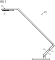
- a table lamp 100 is shown as a preferred embodiment of an LED lamp 100 according to the invention, which can preferably be used as a desk lamp 100.
- the table lamp 100 comprises a light head 50.
- the light head 50 has a light module 51 with several LED arrangements, here specifically, for example, two LED arrangements 1, 2 each with an LED pair with two individual LEDs (as in FIG Figure 3 shown).
- One LED arrangement 1 contains LEDs which emit cold white light with a strong maximum in the blue range around 400 nm.
- these can be LEDs of the type XLamp XM-L KW-U2 from Cree.
- the other LED arrangement 2 contains LEDs which emit more warm white light with a strong maximum in the yellow-red range around 600 nm.
- these can be LEDs of the type XLamp XM-L2 WW-T3 from Cree.
- the LED arrangements are soldered in the light module 51 on an LED board, for example a metal core board (not shown).
- the light 100 has a control module 41, which is located in a lower area of the light arm is housed and is connected to the light module 51 via lines. Part of this control module 41 is also an operating module 10.
- the operating module 10 can be operated by hand by a user by touching a control surface.
- the light module 51 also includes a reflector arrangement, which ensures that the light is emitted at a certain beam angle, as well as a diffuser arrangement, for example here in the form of a simple frosted glass pane or the like, which is used by the various LEDs of the LED arrangements 1, 2 scatters the emitted light and mixes it so well that an area illuminated with it is evenly illuminated.
- the light module 51 also has suitable devices, such as cooling fins or the like, in order to ensure that the excess heat is dissipated.
- the LED light 100 shown is a relatively simple embodiment with only one light head 50 and one light module 51.
- the LED light 100 could also have several light heads or light modules, for example as a floor lamp a double light head in different directions downwards . It is also possible that the direction of radiation from the light head goes upwards so that the lamp acts like a ceiling washer or to the side as a wallwasher.
- Other possible variants are lamps with light heads that can optionally or simultaneously emit light in two different directions, for example with two light modules with their own LED arrangements, with one light module shining downwards and the other upwards as a ceiling washlight and the light modules independently or in Combination can be operated.
- FIG. 2 shows a control arrangement 40 for an LED lamp 100.
- the control arrangement 40 comprises a control device 41 arranged on the side of the LED lamp 100, for example here in the form of the control module 41 which is arranged in the lower part of the arm of the LED lamp 100 (see FIG Figure 1 ).
- this control module 41 comprises an operating module 10 with a plurality of operating elements 11, 15, 18, here preferably in the form of "buttons" which act capacitively on contact.
- a mobile terminal 60 and / or an external memory there are further interfaces 42, 43 for direct or indirect coupling with a mobile terminal 60 and / or an external memory (not shown).
- One interface 43 is a plug interface 43, for example a USB interface 43, to connect the mobile terminal or a USB memory or the like to the control module 51 and / or as a charging interface for charging a mobile terminal.
- the other interface 42 is a wireless interface 42, preferably in the short-range radio range, specifically a preferred Bluetooth interface 42 here.
- a mobile terminal 60 with a graphical user interface 61, preferably a smartphone, can also be used via this wireless interface 42.
- a clock with a corresponding function or the like can be coupled to the LED lamp 100.
- An app that offers control functionality for the LED light 100 is implemented on this mobile terminal device 60. For example, a spectrum control curve can be determined in this way, and values for this spectrum control curve can be transmitted to the control module 41 for controlling the LED arrangements 1, 2.
- the control module 41 is a microcontroller 20, which here controls an LED current controller 30 of the control module 41, via which the LED arrangements 1, 2 are in turn controlled or energized in a pulse width modulation method.
- the LED current control 30 can comprise a device 31 for total current control for both LED arrangements 1, 2 and a device 32 for current supply selection, ie which portion of the total current is made available to which of the LED arrangements 1, 2. The total current is then appropriately divided into phases via a current switch 33.
- FIG Figures 3 to 5 explained in more detail.
- the total current and the proportion of the total current for the individual LED arrangements 1, 2 are ultimately specified by the microcontroller 20, which controls the LED current control 30.
- the microcontroller 20 is given a spectrum control function STK, here in the form of a time-dependent, in particular circadian, spectrum control curve STK, according to which the color temperature is automatically changed to match the user's daily course. If the user has deactivated such a function with a spectrum control curve STK, a constant set value can also be specified for the microcontroller as the spectrum control function (i.e.
- a time-constant function the value being valid until the user presses a key again for setting the color temperature, for example with a specific color temperature controller 11 on the operating module 10 or a corresponding one virtual setting controller on the graphical user interface 61 of the app of the mobile terminal 60, prescribes a new value. This depends on which function the user has set.
- the dimming, d. H. the setting of the brightness or the total power (ultimately here the total current) of the LED arrangements 1, 2 takes place via a suitable dimming button arrangement 18 (here symbolized by only one dimming button) on the operating module 10 or a corresponding functionality on the mobile terminal device 60.
- This setting of the overall brightness is independent of the setting of the color temperature (except in the Boost mode, if applicable), i. H. even if the color temperature is changed, the total output of the LED arrangements 1, 2 remains the same. Only the power is distributed differently to the LED arrangements 1, 2, so that the currently specified color temperature is achieved.
- Figure 2 shows only in a simplified manner the components essential for the invention and that further components can also belong to the entire control arrangement 40, for example further mobile terminals or PCs coupled via the interfaces.
- the control device 41 can also have further components and assemblies, such as one or more power supply units, voltage converters, possibly additional storage units, interfaces, further processors, display elements, etc.
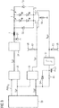
- FIG 3 shows in more detail a circuit diagram with which such a control of the LED arrangements 1, 2 can be implemented, only the microcontroller 20 with the circuit for current control being shown here.
- the in Figure 3 illustrated embodiment a PWM current signal I GP for the total LED current (hereinafter referred to as PWM total current signal) and a PWM current signal I WP for one of the two LED arrangements 1, 2, here the warm white second LED Arrangement 2, generated.
- the PWM current signals are each logical control signals (with "0" or "1") that are intended to control the current.
- the PWM current signal I WP for the second LED arrangement 2 like the total PWM current signal I GP, is fed to an XOR gate 36 (exclusive-OR gate). The result is then a PWM current signal I KP for the first LED arrangement 1 with the cold white LEDs.
- This PWM current signal I KP is applied to a switching input of a first transistor T1, here a MOSFET.
- a second transistor T2, here also one MOSFET, for the second, warm white LED arrangement 2 is controlled at its switching input by the PWM current signal I WP for the second LED arrangement 2.
- the switching inputs of the transistors T1, T2 are each connected to the signal lines of the corresponding PWM current signals I KP , I WP and to a reference potential VR, for example 5 V, via resistors R2, R3.
- a reference potential VR for example 5 V
- the total current of the LED arrangement and thus the brightness of the light module is, as mentioned, ultimately specified by the PWM total current signal I GP , which is first fed from the microcontroller 20 to a logic AND gate 35, which also has a logic enable signal PWM E on an inverted input is supplied.
- the release signal PWM E is output by the microcontroller 20 in such a way that the logical PWM total current signal I GP is output accordingly at the output of the AND gate 35 only when the microcontroller has safely started up in a defined state.
- the total PWM current signal I GP coming from AND gate 35 is then fed to an input (hereinafter also referred to as "dimming input") of a current regulator 34, here a step-down regulator module 34, for example of the LM3406 type, with which the total current predetermined by the PWM total current signal I GP through the LED arrangements 1, 2 can be regulated.
- a freewheeling diode D1 to ground and an inductance L1 between the output of the step-down controller module 34 and the anode connections of the LED arrangements 1, 2, which are parallel are switched, switched.
- two free-wheeling diodes D2, D3 are connected in parallel to the LED arrangements 1, 2 in order to avoid voltage peaks at the LEDs.
- the LED arrangements 1, 2 are connected to the aforementioned transistors T1, T2.
- the transistors T1, T2 are each connected to ground via a common resistor R4. This resistor R4 is used to measure the total current. The current value determined there is fed as an actual value to the step-down controller module 34 (in Figure 3 not shown).
- the PWM current signal I WP for the second LED arrangement 2 is not passed directly to the transistor T2, but via a circuit arrangement consisting of a diode D4, a resistor R1 connected in parallel, a subsequent Schmitt trigger 37 and one between the diode D4 and the resistor R1 on the one hand and the Schmitt trigger 37 on the other hand, capacitor C1 connected to ground.
- a circuit arrangement consisting of a diode D4, a resistor R1 connected in parallel, a subsequent Schmitt trigger 37 and one between the diode D4 and the resistor R1 on the one hand and the Schmitt trigger 37 on the other hand, capacitor C1 connected to ground.
- the microcontroller 20 If, on the other hand, the microcontroller 20 outputs a "0" as the PWM current signal I WP for the second LED arrangement 2 in order to switch off the current through the second LED arrangement 2 again, the capacitor C1 must first be discharged with a delay via the resistor R1 and the Schmitt trigger 37, as a comparator, switches over again only after a predetermined threshold value at its output. This ensures a delay in the shutdown of approx. 10 ⁇ s.
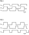
- FIG Figure 4 A pulse diagram of the PWM current signals I GP , I WP , I KP in this circuit arrangement is shown in FIG Figure 4 shown.
- the upper pulse diagram shows the total PWM current signal I GP output by the microcontroller and the middle pulse diagram shows the PWM current signal I WP for the warm white, second LED arrangement 2.
- the lower pulse diagram shows the PWM current signal I KP generated therefrom by the logic module 36 for the cold white, first LED arrangement 1. The switching status is shown over time.
- the delayed forwarding to transistor T2 is symbolized by the dashed falling edge on the pulses of the PWM current signal I WP for the warm white, second LED arrangement 2, so that when the current is switched off for the warm white LED arrangement 2, the PWM is activated shortly beforehand -Current signal I KP for the cold white LED arrangement 1 is switched up, ie that these signals overlap. Since at the same time the total current remains constant, as is shown in the upper curve, this means that the current of the warm white LED arrangement 2 is shut down, while the current for the cold white LED arrangement 1 is started up at the same time.
- a PWM current control signal for the current of the cold white and warm white LED arrangements can also be generated directly by the microcontroller. It can be ensured that the current of the warm white LED arrangement 2 can only be switched off after the current for the cold white LED arrangement 1 has been switched on and the total current has been divided between both branches.
- a PWM current signal I GP for the common total LED current can be generated via a logical OR link (which can be generated simply with two diodes and a resistor, for example), which in turn can then be generated can be given to the dimming input of the LED current regulator (ie the step-down regulator).
- the LED current can then be switched to the cold white and warm white LED arrangement 1, 2 again via transistors.
- FIG Figure 5 A corresponding diagram of these PWM current signals I GP , I WP , I KP is alternatively shown in FIG Figure 5 shown.
- the upper diagram shows the PWM current signal I WP output by the microcontroller for the warm white LED arrangement 2
- the middle diagram shows the PWM current signal I KP for the cold white LED arrangement 1, which is also output by the microcontroller
- the lower diagram shows that of the two PWM total current signal I GP generated via an OR link in the upper curves, which is sent to the dimming input of the controller.
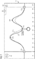
- a circadian time-dependent spectrum control curve STK can be generated for the microcontroller 20.
- the total light spectrum or the total light color temperature of the light emitted by the light module 51 of the LED lamp 100 is established over the course of the day.
- the current spectrum control curve STK is shown over time on the touch display of the terminal 60.
- the color temperature of the total light of the light module 51 of the LED light 100 to be controlled is plotted here in the spectrum control curve STK over time.
- the display is also rotated in the usual way, so that the time axis is always at the bottom.
- the timescale is shown below. The color temperature increases from bottom to top. It starts at the bottom at approx. 2700 K (warm white light) and goes up to approx. 6500 K (cold white light).
- the section can be enlarged or reduced using zoom buttons 62.
- zooming with the usual gestures on the touch display is also possible (for example, pulling the fingers apart or pushing the fingers together, etc.).
- toggle buttons 63 are also shown here, if the app is to be used to control different LED lights or different independent light modules with their own independent spectrum control curves.
- the current window or the app can be closed via a button 64. It will be in this context pointed out that the term "key" is to be understood as virtual keys, so that when the screen is touched, the respective function is triggered at this point.
- the spectrum control curve STK is defined by several support points SP1, SP2, ... SP6. At each of the support points SP1, SP2, ... SP6, a precise color temperature value (e.g. the mean value or the maximum of the total light spectrum) is stored for the relevant point in time.
- These support points SP1, SP2, ... SP6 are either, as will be done later will be explained, initially set for a start spectrum control curve. However, they can also be specified or changed individually by the user, as can be done using Figure 7 is yet to be explained. In Figure 6 only six such bases are shown. More support points can also be used to define a curve, for example twelve or twenty-four support points distributed over the day.
- the spectrum control curve STK is then placed through these support points as an interpolation function, possibly in sections, for example as a spline.
- the associated time value is shown enlarged and the support point SP5 is marked, for example, by a line or the like.
- the first support point SP1 is at the same time a support point with which it is specified that the light module 51 is switched on at this point in time. This is in the in Figure 6 example shown at 9 a.m.
- the last support point is accordingly also a point in time at which the light module 51 is switched off again. This is the time at 7:30 p.m.
- the user can also change the spectrum control curve STK by changing the support points SP1, SP2, ... SP6.
- the original spectrum control curve STK as in FIG Figure 6 is the original spectrum control curve STK as in FIG Figure 6 as well as a new spectrum control curve STK 'generated by moving the support points SP2, SP3 and SP4 and removing the fifth support point SP5.
- the support points SP1, SP2, ... SP6 can be shifted in two directions, namely simply only in the color temperature direction, ie perpendicular to the time axis, as is the case with the support points SP2, SP4. Shifting along the time axis is also possible, as is the case with the third support point SP3.
- the touchscreen When touching the support point (the touchscreen preferably reacts in such a way that the user touches the curve just below the support point so as not to obscure the support point itself), an enlarged support point is displayed underneath, at which the user touches with his finger Base can lead well.
- the current color temperature value for example, can be displayed, such as 3200 K here (i.e. still in the warm white area) at support point SP3.
- the change in the spectrum control curve STK ie the shift in the support points SP1, SP2, ... SP6, is also registered and stored. This can be done both in the app, ie in the memory of the mobile terminal, and in the microcontroller 20 or in the associated memory 21 of the microcontroller 20 in the control module 41 (see FIG Figure 2 ) of the LED light itself.
- the change in the curve inserted by the user the day before can be taken into account, but preferably only by a reduced part, for example by 30%. If the user makes the same or similar change for three days in a row, this leads to a changed curve in the desired shape.
- the user can of course also set a mode in which the changes are immediately accepted as fixed and not just as changes made individually for this day, which are then taken into account in the learning mode if necessary.
- Figure 8 shows an example of how the color temperature CT is temporarily changed when the boost mode is switched on, ie when the user presses a boost button to transmit a short-term dose change signal DHS, here a dose increase signal (DHS).
- DHS dose increase signal
- a change could also be made to increase the proportion of warm light for a temporary relaxation phase.
- the color temperature CT as a percentage of the cold white light kw (that is, the light of the first LED arrangement 1) or the warm white light ww (that is the light of the first LED arrangement 1).
- a boost button 15 is located, for example, on the operating module 10 of the LED light 100 (see Figures 1 and 2 ).
- a corresponding virtual button can also be made available by the app on the graphical user interface 61 of the portable terminal 60. Without pressing such a boost button, the control of the color temperature of the LED lighting module 51 would normally be in accordance with that in FIG Figure 8 shown spectrum control curve, which in turn is defined by support points SP1, SP2, ... SP4 over time t. At any point in time t B , however, the user decides that he needs a light refreshment.
- Boost button After pressing the Boost button, in a relatively short rise time .DELTA.t r of preferably about one Second ensures that the cold white LED arrangement 1 is run up to maximum power, ie with 100% power (whereas in normal operating mode, for example, the total power is a maximum of 80% of the possible power). In other words, 100% of the available current is used to operate the first LED arrangement 1.
- the warm white LED arrangement 2 is not supplied with power at all during this time. This means that the color temperature CT is also 100% kw. This leads to the fact that a maximum blue component (in the range around 450 nm) is emitted, by means of which the melatonin output of the user can be reduced for a short time and thus the effect of the rather refreshing happiness hormone serotonin can be increased.
- the LED light or the light module is preferably constructed in such a way that the illuminance is then at least 80 lux, but particularly preferably higher, for example approx. 200 lux.
- this increase in output of the cold white LEDs and color shift to the maximum blue component only takes place for a limited boost period ⁇ tB of, for example, 10 minutes.
- ⁇ tB boost period
- ⁇ t f the output of the cold white LED arrangement 1 and the output of the warm white LED -Arrangement 2 is set again so that the total light spectrum reaches the color temperature value of the control curve STK at the time then present.
- the LED light-emitting module 51 is then operated again quite normally according to the spectrum control curve STK.
- the spectrum control curve STK is normally not influenced by this. In principle, however, it is also possible that the activation of the boost mode is saved at this point in time and that this is incorporated into a long-term change in the control curve over several days if the user activates the boost mode on several days in a row at about the same time. Button pressed, as this indicates that the spectrum control curve is not optimally set for the user and that he generally needs a little more blue light at this time of the day.
- a monitoring counter is also triggered that runs for at least an acceptance period AZ. While this counter is running, the number of times the user presses the boost button is counted, and it is stored in the microcontroller that a certain number of boost periods ⁇ t B may be present within the acceptance period AZ, for example that the user is within four Hours can only use the boost mode twice. Switches If the user activates the boost mode a third time within four hours, this has no effect.
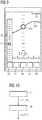
- Figure 9 shows, this time in portrait view, another user interface (another window or a menu) of the app for controlling the LED light on a mobile device 60.
- another user interface another window or a menu
- the app for controlling the LED light on a mobile device 60.
- FIG. 9 shows, this time in portrait view, another user interface (another window or a menu) of the app for controlling the LED light on a mobile device 60.
- FIG. 9 shows, this time in portrait view, another user interface (another window or a menu) of the app for controlling the LED light on a mobile device 60.
- another window or a menu for controlling the LED light on a mobile device 60.
- This toolbar can be called up, for example, when the user, with the app switched on and the spectrum control curve displayed, moves his finger upwards across the screen, starting from the edge, in order to "pull" the toolbar out of the edge of the page.
- This toolbar contains, on the one hand, a menu key 69 with which a main menu and, below it, further functions (or windows) can be switched on, for example a window for calling up an initialization mode in order to first create an individual start spectrum control curve that is as well-adapted as possible for the user .
- the toolbar also includes a boost button 65 for triggering the boost mode explained above.
- An on / off button 66 is also provided here.
- a further key 67 can be used to set whether the control curve STK is actually adjusted when the currently visible support point on the control curve is shifted, or whether this should only be a short-term individual adjustment of the control curve for this one day.
- a virtual dimming controller 70 is opened via a virtual dimming button 68.
- a virtual point 71 can be moved on this in order to vary the brightness of the LED light module, parallel to the possibility of using a corresponding dimmer control in the operating module 10 on the LED light 100.
- Said app can be downloaded to the mobile terminal device 60 in the usual way, for example from the Internet.
- it is also possible to couple the terminal 60 to the LED light 100 via the wireless interface for example by setting a search mode in the usual way and at the same time also setting a search mode on the LED light and when it is found the devices can then be given a confirmation signal in the app and / or the operating module of the LED light in order to carry out the coupling.
- Coupling by means of a near-field communication interface or reading in a scan code on the LED light would also be conceivable.
- Figure 10 shows a flow chart of how, for example, when a user uses an LED light for the first time, an individual start spectrum control curve S-STK can be generated for this user.
- the user is offered by the app after the coupling or selection or confirmation of the coupling with the LED light to carry out an initialization mode. If this is accepted by the user, various user-specific parameters P1, P2, ... are queried within a first initialization step I. There is no query at which times exactly which interpolation points are set with which values, but instead, user behavior-specific parameters are queried, such as the time of the start of work, the time of the end of work, the time and duration of the breaks.
- this also includes a purely user feeling-specific parameter query, namely the query of the time of highest willingness to perform, in which the user is asked in which five consecutive hours he would work his working time, if he could freely determine this, as well as a query of an hour, in which he feels he has the highest willingness to perform.
- the start spectrum control curve S-STK is then calculated on the basis of these parameters P1, P2, ... in a subsequent curve determination step II.
- the start spectrum control curve S-STK could then be selected such that the start of the curve is 30 minutes before the start of work and the curve has a 60% cold white component.
- the end of the curve can be 30 minutes after the end of work, with a 0% cold white component.
- a support point could be set 30 minutes before the lunch break with 40% cold white, at and during the lunch break the cold white component is then set to 20% and at the end of the lunch break and 30 minutes after the lunch break, two support points with 80% cold white Share set.
- support points with a 70% cold white share could be selected for all times in the period of the selected highest willingness to perform that are not influenced by breaks or the end of work, whereby the one hour of the particularly highest willingness to perform a 90% Preserves cold white content.
- the support points which are set on the basis of the freely selectable maximum willingness to perform, are set in such a way that they do not influence the breaks or the end of work selected by the external specifications.
- This start spectrum control curve S-STK can then be transmitted from the mobile terminal 60 via the wireless interface to the control module or the microcontroller 20 in the control module 41 of the LED light 100. It is sufficient for the list of support points to be transferred.
- the microcontroller and the app can calculate the same interpolation function as a spectrum control curve.
- the microcontroller can store the coefficients of a polynomial of the nth order for the interpolation function. By means of simple multiplication processes, the microcontroller 20 can then quickly calculate the appropriate value of the curve at any point in time and output corresponding PWM current control signals, as has already been done with the aid of FIG Figures 1 to 5 was explained.
- the new support points are transmitted again to the microcontroller of the control module of the LED light via the wireless interface, which then also calculates and stores the new coefficients.
- the user can also switch off the use of the spectrum control curve at any time and switch to keeping the spectrum control function constant for the next period and z.
- B. set the color temperature using a simple slider, the microcontroller then holding this constant value. In this case, too, it is possible to select the boost function and then return to the predetermined constant value according to the spectrum control function.
- the LED luminaire not only to have two LED arrangements with different light spectra but possibly also more than two different LED arrangements with different light colors or spectra, in particular also any colored LEDs, for example - but not exclusively - amber, blue, red, yellow-red and / or green LEDs. It could also z. B. one or more additional LED arrangements can be provided, which are only switched on in boost mode to the first LED arrangement to reinforce their effect.
- the different LED arrangements can also be distributed over them, ie they can be located in different light heads or light modules. In particular, if several light heads or light modules emit light in different directions, these can z. B. each have several LED arrangements and / or are controlled independently of one another according to the method according to the invention, also operated independently of one another with different spectrum control functions (for example with different circadian variations) and also with separately triggered boost modes.
Landscapes
- Circuit Arrangement For Electric Light Sources In General (AREA)
Claims (15)
- Procédé de commande d'une lampe à LED (100) qui comprend au moins un premier agencement de LED (1) et un deuxième agencement de LED (2), dans lequel le premier agencement de LED (1) et le deuxième agencement de LED (2) émettent de la lumière avec des spectres lumineux différents pendant le fonctionnement et de préférence le premier agencement de LED (1) émet une proportion plus élevée de lumière bleue que le deuxième agencement de LED (2),
dans lequel les proportions de la lumière émise par le premier agencement de LED (1) et le deuxième agencement de LED (2) dans un spectre lumineux total des agencements de LED (1, 2) sont commandées selon une fonction de commande de spectre prédéterminée (STK), caractérisé en ce que
à la réception d'un signal de changement de dose à court terme (DHS), de préférence un signal d'augmentation de dose (DHS), au moins le premier agencement de LED (1) est commandé pour une durée prédéfinie de changement de dose (ΔtB) s'écartant de la fonction de commande de spectre spécifiée (STK) de sorte qu'il soit mis en fonctionnement avec une puissance minimale prédéterminée ou la proportion de la lumière de ce premier agencement de LED (1) dans le spectre lumineux total des agencements de LED (1, 2) est un certain minimum, et après la période de changement de dose prédéfinie (ΔtB), les agencements de LED (1, 2) peuvent être commandés selon une règle de commande prédéterminée de telle sorte que le spectre lumineux total corresponde à nouveau à la valeur actuelle de la fonction de commande de spectre prédéterminée (STK). - Procédé selon la revendication 1, dans lequel la fonction de commande de spectre (STK) comprend une courbe de commande de spectre (STK) dépendant du temps, de préférence circadienne.
- Procédé selon la revendication 1 ou 2, dans lequel après avoir reçu le signal de changement de dose à court terme (DHS), le premier agencement de LED (1) fonctionne dans l'intervalle de temps de changement de dose prédéfini (ΔtB) avec une proportion maximale du spectre lumineux total, de préférence avec une puissance maximale.
- Procédé selon une quelconque des revendications précédentes, dans lequel, après la réception d'un signal de changement de dose à court terme (DHS), le deuxième agencement de LED (2) est éteint ou mis en fonctionnement en dessous d'une puissance définie.
- Procédé selon une quelconque des revendications précédentes, dans lequel l'intervalle de temps de changement de dose (ΔtB) est d'un maximum de 30 minutes, de préférence d'un maximum de 20 minutes, de manière particulièrement préférée d'un maximum de 10 minutes.
- Procédé selon une quelconque des revendications précédentes, dans lequel après la période de changement de dose prédéfinie (ΔtB), les agencements de LED (1, 2) sont commandés de sorte que la proportion de la lumière du premier agencement de LED (1) dans le spectre lumineux total sur une période de temps de réinitialisation spécifique (Δtf), de préférence d'au moins 30 s, soit réduite jusqu'à ce que le spectre lumineux total corresponde à nouveau à la fonction de commande de spectre spécifiée (STK).
- Procédé selon une quelconque des revendications précédentes, dans lequel dans une période d'acceptation prédéterminée (AZ) de préférence d'au moins quatre heures, seul un certain nombre maximum de signaux de changement de dose à court terme (DHS) sont acceptés, dans lequel une commande s'écartant de la fonction de commande de spectre spécifiée (STK) d'au moins le premier agencement de LED (1) est exécutée et lorsqu'un autre signal de changement de dose à court terme (DHS) est reçu après que le nombre maximum de signaux de changement de dose à court terme (DHS) a été atteint, aucun écart par rapport à la fonction de commande du spectre (STK) spécifiée ne se produit.
- Procédé selon une quelconque des revendications précédentes, dans lequel la fonction de commande de spectre (STK) est sortie graphiquement sur une interface d'utilisateur graphique (61) et peut être modifiée à l'aide de l'interface d'utilisateur graphique (61).
- Procédé selon une quelconque des revendications précédentes, dans lequel une fonction de commande de spectre (STK) et/ou un signal de changement de dose à court terme (DHS) d'un terminal mobile (60) et/ou d'un PC, de préférence sans fil, de manière particulièrement préférée via une liaison radio à courte portée, sont transmis à un dispositif de commande (41) de la lampe à LED (100).
- Procédé selon une quelconque des revendications 2 à 9, dans lequel pour la courbe de commande de spectre (STK) à des instants différents dans chaque cas, des valeurs de points de support sont spécifiées comme points de support (SP1, SP2, ..., SP5) et sur la base de ces points de support (SP1, SP2, ..., SP5), une fonction d'interpolation est déterminée sous la forme d'une courbe de commande de spectre (STK).
- Procédé selon une des revendications précédentes, dans lequel lorsqu'un signal de changement manuel est reçu d'une interface d'utilisateur, la fonction de commande de spectre (STK) est modifiée au moins localement et cette modification locale est au moins partiellement prise en compte dans une nouvelle exécution ultérieure de la fonction de commande de spectre (STK).
- Procédé selon une quelconque des revendications 2 à 11, dans lequel dans une procédure d'initialisation via une interface utilisateur (61) des paramètres spécifiques à l'utilisateur (P1, P2, ...) sont interrogés et sur la base des paramètres spécifiques à l'utilisateur (P1, P2, ...), une courbe de commande de spectre de démarrage individuelle spécifique à l'utilisateur (S-STK) est déterminée.
- Procédé selon une quelconque des revendications précédentes, caractérisé en ce que le premier agencement de LED (1) et le deuxième agencement de LED (2) sont chacun commandés dans un procédé de modulation de largeur d'impulsion, dans lequel les agencements de LED (1, 2) sont mis en fonctionnement avec un courant total commun et ce courant total est commuté vers les différents agencements de LED (1, 2) à des moments différents
et au moins partiellement lorsque le courant total est commuté d'un agencement de LED (1) à un autre agencement de LED (2), les agencements de LED (1, 2) fonctionnent en parallèle pendant une courte période. - Lampe à LED (100) comportant au moins un premier agencement de LED (1) et un deuxième agencement de LED (2), dans lequel le premier agencement de LED (1) et le deuxième agencement de LED (2) en fonctionnement émettent de la lumière avec différents spectres lumineux et de préférence, le premier agencement de LED (1) émet une proportion plus élevée de lumière bleue que le deuxième agencement de LED (2),
et un agencement de commande (40) qui est conçu pour commander les proportions de la lumière émise par le premier agencement de LED (1) et le deuxième agencement de LED (2) dans un spectre lumineux total des agencements de LED (1, 2) selon une fonction de commande de spectre prédéterminée (STK), caractérisée en ce que le dispositif de commande (40) a au moins une interface de changement de dose à court terme (15, 65) et est conçu de telle sorte qu'à la réception d'un signal de changement de dose à court terme (DHS), de préférence un signal d'augmentation de dose (DHS), de cette interface de changement de dose à court terme (15, 65) au moins Le premier agencement de LED (1) soit commandé pendant une durée prédéfinie de changement de dose (ΔtB) s'écartant de la fonction de commande de spectre spécifiée (STK) de sorte qu'il fonctionne avec une puissance minimale spécifiée ou la proportion de lumière provenant de ce premier agencement de LED (1) dans le spectre lumineux total des agencements de LED (1, 2) est une certaine proportion minimale, et après l'intervalle de temps de changement de dose prédéfini (ΔtB), les agencements de LED (1, 2) sont commandés selon une règle de commande prédéterminée de sorte que le spectre lumineux total corresponde à nouveau à la fonction de commande de spectre spécifiée (STK). - Lampe à LED (100) selon la revendication 14, dans laquelle le dispositif de commande (40) a une interface de gradateur (18, 68) et est conçu de telle sorte qu'au moyen de l'interface de gradateur (18, 68) indépendamment de la fonction de commande de spectre (STK) la quantité totale de lumière des agencements de LED (1, 2) soit réglable.
Applications Claiming Priority (2)
| Application Number | Priority Date | Filing Date | Title |
|---|---|---|---|
| DE102014115076.7A DE102014115076A1 (de) | 2014-10-16 | 2014-10-16 | Verfahren zur Ansteuerung einer LED-Leuchte und LED-Leuchte |
| PCT/EP2015/072854 WO2016058849A1 (fr) | 2014-10-16 | 2015-10-02 | Procédé de commande d'une lampe à led et lampe à led |
Publications (2)
| Publication Number | Publication Date |
|---|---|
| EP3207763A1 EP3207763A1 (fr) | 2017-08-23 |
| EP3207763B1 true EP3207763B1 (fr) | 2021-05-12 |
Family
ID=54249499
Family Applications (1)
| Application Number | Title | Priority Date | Filing Date |
|---|---|---|---|
| EP15774612.4A Active EP3207763B1 (fr) | 2014-10-16 | 2015-10-02 | Procédé de commande d'une lampe à led et lampe à led |
Country Status (3)
| Country | Link |
|---|---|
| EP (1) | EP3207763B1 (fr) |
| DE (1) | DE102014115076A1 (fr) |
| WO (1) | WO2016058849A1 (fr) |
Families Citing this family (6)
| Publication number | Priority date | Publication date | Assignee | Title |
|---|---|---|---|---|
| DE102015105479A1 (de) | 2015-04-10 | 2016-10-13 | "Durable" Hunke & Jochheim Gmbh & Co. Kommanditgesellschaft | Standleuchte |
| DE102016104452A1 (de) | 2016-03-11 | 2017-09-14 | "Durable" Hunke & Jochheim Gmbh & Co. Kommanditgesellschaft | Regelung einer LED-Anordnung und LED-Beleuchtungssystem |
| US10085314B1 (en) | 2018-03-14 | 2018-09-25 | Infineon Technologies Ag | Light emitting diode driver for load changes |
| DE102018106089A1 (de) | 2018-03-15 | 2019-09-19 | Ledvance Gmbh | Beleuchtungssystem zur dynamischen Beleuchtungssteuerung |
| DE102018115132A1 (de) * | 2018-06-22 | 2019-12-24 | Vossloh-Schwabe Lighting Solutions GmbH & Co. KG | Beleuchtungssystem für die Tier- und Pflanzenhaltung |
| DE102021103698A1 (de) | 2021-02-17 | 2022-08-18 | Ledvance Gmbh | Leuchtvorrichtung zum Erzeugen eines weißen Mischlichts mit steuerbaren Spektraleigenschaften |
Family Cites Families (12)
| Publication number | Priority date | Publication date | Assignee | Title |
|---|---|---|---|---|
| JP3328170B2 (ja) * | 1997-08-13 | 2002-09-24 | 日本電気株式会社 | 光通信送信装置 |
| WO2013111134A1 (fr) * | 2012-01-24 | 2013-08-01 | Yechezkal Evan Spero | Système d'éclairage commandé par un détecteur |
| RU2468838C2 (ru) * | 2007-03-09 | 2012-12-10 | Конинклейке Филипс Электроникс Н.В. | Осветительная система для энергетической стимуляции |
| BRPI0906849B8 (pt) * | 2008-01-17 | 2021-07-27 | Koninklijke Philips Nv | dispositivo de iluminação, e, método para prover um estímulo para despertar por meio de um dispositivo de iluminação |
| US20130307419A1 (en) * | 2012-05-18 | 2013-11-21 | Dmitri Simonian | Lighting system with sensor feedback |
| DE102009040283A1 (de) * | 2009-09-04 | 2011-03-10 | Tridonic Ag | Betrieb von pulsmodulierten LEDs |
| ES2930370T3 (es) * | 2009-10-08 | 2022-12-09 | Delos Living Llc | Sistema de iluminación LED |
| US9967940B2 (en) * | 2011-05-05 | 2018-05-08 | Integrated Illumination Systems, Inc. | Systems and methods for active thermal management |
| JP5649537B2 (ja) * | 2011-08-12 | 2015-01-07 | 株式会社東芝 | 照明装置 |
| WO2013071181A2 (fr) * | 2011-11-11 | 2013-05-16 | Cirrus Logic, Inc. | Mélange de couleurs de sources de lumière électroniques avec corrélation entre un angle de dispositif d'atténuation à coupure de phase et une fonction de rayonnement de corps noir prédéterminée |
| JP2014102978A (ja) * | 2012-11-20 | 2014-06-05 | Toshiba Corp | 照明装置 |
| CN104869806B (zh) * | 2012-12-21 | 2019-03-12 | 飞利浦灯具控股公司 | 用于对接至少一个照明系统的园艺照明接口 |
-
2014
- 2014-10-16 DE DE102014115076.7A patent/DE102014115076A1/de not_active Withdrawn
-
2015
- 2015-10-02 EP EP15774612.4A patent/EP3207763B1/fr active Active
- 2015-10-02 WO PCT/EP2015/072854 patent/WO2016058849A1/fr not_active Ceased
Non-Patent Citations (1)
| Title |
|---|
| None * |
Also Published As
| Publication number | Publication date |
|---|---|
| EP3207763A1 (fr) | 2017-08-23 |
| DE102014115076A1 (de) | 2016-04-21 |
| WO2016058849A1 (fr) | 2016-04-21 |
Similar Documents
| Publication | Publication Date | Title |
|---|---|---|
| EP3207764B1 (fr) | Procédé pour commander un luminaire à del et luminaire à del | |
| EP3207763B1 (fr) | Procédé de commande d'une lampe à led et lampe à led | |
| DE102014115082A1 (de) | Verfahren zur Ansteuerung eines LED-Beleuchtungssystems und LED-Beleuchtungssystem | |
| EP3766305B1 (fr) | Système d'éclairage pour un contrôle d'éclairage dynamique | |
| DE102017108687A1 (de) | Festkörper-Zirkadianrhythmus-Lampe und zugehöriges Steuerungsverfahren | |
| EP1587347B1 (fr) | Dispositif pour contrôler une pluralité de luminaires | |
| EP3013123B1 (fr) | Système d'éclairage et procédé de commande correspondant | |
| EP2031940A2 (fr) | Agencement de grappe DEL doté d'un commutateur à courant continu | |
| DE102010030501A1 (de) | Vorrichtung und Verfahren zum Anpassen eines Circadianen Rhythmus | |
| DE102018106586A1 (de) | Beleuchtungssystem und mobiler Körper | |
| WO2010108982A1 (fr) | Appareil de commande permettant une réduction de l'intensité et système d'éclairage destiné à accroître la durée de vie de del ou de delo | |
| EP3009733B1 (fr) | Module de commande et systeme d'eclairage, avec communication sans fil | |
| WO2019141535A1 (fr) | Commande de systèmes d'éclairage | |
| DE202010013133U1 (de) | Lampenbetriebsgerät mit zugeordneter Timereinheit | |
| DE102018216474B4 (de) | Verfahren zum zuordnen von lichtsensoren für die beleuchtungsregelung in einem beleuchtungssystem | |
| EP3418628B1 (fr) | Éclairage doté de fonctions multiples | |
| EP2375869A2 (fr) | Procédé et agencement de fonctionnement d'une source lumineuse à émission de lumière modifiable | |
| AT14831U1 (de) | Beleuchtungsvorrichtung für ein Patientenzimmer und Beleuchtungssystem | |
| DE102013008337A1 (de) | Beleuchtungssystem für ein Gebäude mit einer Beleuchtungsanordnung mit einstellbarem Lichtspektrum | |
| DE202014105984U1 (de) | Betriebsgerät zum Betreiben von Leuchtmitteln | |
| DE102016104347A1 (de) | Vereinfachtes Inbetriebnahmekonzept zum Ansteuern von Aktoren einer Gebäudeinstallation | |
| DE102014109145A1 (de) | Computerbildschirm umfassend eine Matrixanzeigefläche und eine Statusanzeige | |
| EP3772869A1 (fr) | Dispositif d'éclairage commandé sans couplage arrière | |
| AT516635B1 (de) | Verfahren zur steuerung einer beleuchtungseinrichtung | |
| EP1973389A2 (fr) | Gradateur de lumière numérique pour lampes à économie d'énergie |
Legal Events
| Date | Code | Title | Description |
|---|---|---|---|
| STAA | Information on the status of an ep patent application or granted ep patent |
Free format text: STATUS: THE INTERNATIONAL PUBLICATION HAS BEEN MADE |
|
| PUAI | Public reference made under article 153(3) epc to a published international application that has entered the european phase |
Free format text: ORIGINAL CODE: 0009012 |
|
| STAA | Information on the status of an ep patent application or granted ep patent |
Free format text: STATUS: REQUEST FOR EXAMINATION WAS MADE |
|
| 17P | Request for examination filed |
Effective date: 20170227 |
|
| AK | Designated contracting states |
Kind code of ref document: A1 Designated state(s): AL AT BE BG CH CY CZ DE DK EE ES FI FR GB GR HR HU IE IS IT LI LT LU LV MC MK MT NL NO PL PT RO RS SE SI SK SM TR |
|
| AX | Request for extension of the european patent |
Extension state: BA ME |
|
| DAV | Request for validation of the european patent (deleted) | ||
| DAX | Request for extension of the european patent (deleted) | ||
| REG | Reference to a national code |
Ref country code: DE Ref legal event code: R079 Ref document number: 502015014712 Country of ref document: DE Free format text: PREVIOUS MAIN CLASS: H05B0033080000 Ipc: H05B0045200000 |
|
| GRAP | Despatch of communication of intention to grant a patent |
Free format text: ORIGINAL CODE: EPIDOSNIGR1 |
|
| STAA | Information on the status of an ep patent application or granted ep patent |
Free format text: STATUS: GRANT OF PATENT IS INTENDED |
|
| RIC1 | Information provided on ipc code assigned before grant |
Ipc: H05B 47/10 20200101ALI20201201BHEP Ipc: H05B 45/46 20200101ALI20201201BHEP Ipc: H05B 45/37 20200101ALI20201201BHEP Ipc: H05B 45/20 20200101AFI20201201BHEP |
|
| INTG | Intention to grant announced |
Effective date: 20201215 |
|
| GRAS | Grant fee paid |
Free format text: ORIGINAL CODE: EPIDOSNIGR3 |
|
| GRAA | (expected) grant |
Free format text: ORIGINAL CODE: 0009210 |
|
| STAA | Information on the status of an ep patent application or granted ep patent |
Free format text: STATUS: THE PATENT HAS BEEN GRANTED |
|
| AK | Designated contracting states |
Kind code of ref document: B1 Designated state(s): AL AT BE BG CH CY CZ DE DK EE ES FI FR GB GR HR HU IE IS IT LI LT LU LV MC MK MT NL NO PL PT RO RS SE SI SK SM TR |
|
| REG | Reference to a national code |
Ref country code: GB Ref legal event code: FG4D Free format text: NOT ENGLISH |
|
| REG | Reference to a national code |
Ref country code: CH Ref legal event code: EP |
|
| REG | Reference to a national code |
Ref country code: DE Ref legal event code: R096 Ref document number: 502015014712 Country of ref document: DE |
|
| REG | Reference to a national code |
Ref country code: IE Ref legal event code: FG4D Free format text: LANGUAGE OF EP DOCUMENT: GERMAN |
|
| REG | Reference to a national code |
Ref country code: AT Ref legal event code: REF Ref document number: 1393054 Country of ref document: AT Kind code of ref document: T Effective date: 20210615 |
|
| REG | Reference to a national code |
Ref country code: SE Ref legal event code: TRGR |
|
| REG | Reference to a national code |
Ref country code: LT Ref legal event code: MG9D |
|
| REG | Reference to a national code |
Ref country code: NL Ref legal event code: MP Effective date: 20210512 |
|
| PG25 | Lapsed in a contracting state [announced via postgrant information from national office to epo] |
Ref country code: FI Free format text: LAPSE BECAUSE OF FAILURE TO SUBMIT A TRANSLATION OF THE DESCRIPTION OR TO PAY THE FEE WITHIN THE PRESCRIBED TIME-LIMIT Effective date: 20210512 Ref country code: LT Free format text: LAPSE BECAUSE OF FAILURE TO SUBMIT A TRANSLATION OF THE DESCRIPTION OR TO PAY THE FEE WITHIN THE PRESCRIBED TIME-LIMIT Effective date: 20210512 Ref country code: HR Free format text: LAPSE BECAUSE OF FAILURE TO SUBMIT A TRANSLATION OF THE DESCRIPTION OR TO PAY THE FEE WITHIN THE PRESCRIBED TIME-LIMIT Effective date: 20210512 Ref country code: BG Free format text: LAPSE BECAUSE OF FAILURE TO SUBMIT A TRANSLATION OF THE DESCRIPTION OR TO PAY THE FEE WITHIN THE PRESCRIBED TIME-LIMIT Effective date: 20210812 |
|
| PG25 | Lapsed in a contracting state [announced via postgrant information from national office to epo] |
Ref country code: NO Free format text: LAPSE BECAUSE OF FAILURE TO SUBMIT A TRANSLATION OF THE DESCRIPTION OR TO PAY THE FEE WITHIN THE PRESCRIBED TIME-LIMIT Effective date: 20210812 Ref country code: PL Free format text: LAPSE BECAUSE OF FAILURE TO SUBMIT A TRANSLATION OF THE DESCRIPTION OR TO PAY THE FEE WITHIN THE PRESCRIBED TIME-LIMIT Effective date: 20210512 Ref country code: PT Free format text: LAPSE BECAUSE OF FAILURE TO SUBMIT A TRANSLATION OF THE DESCRIPTION OR TO PAY THE FEE WITHIN THE PRESCRIBED TIME-LIMIT Effective date: 20210913 Ref country code: RS Free format text: LAPSE BECAUSE OF FAILURE TO SUBMIT A TRANSLATION OF THE DESCRIPTION OR TO PAY THE FEE WITHIN THE PRESCRIBED TIME-LIMIT Effective date: 20210512 Ref country code: LV Free format text: LAPSE BECAUSE OF FAILURE TO SUBMIT A TRANSLATION OF THE DESCRIPTION OR TO PAY THE FEE WITHIN THE PRESCRIBED TIME-LIMIT Effective date: 20210512 Ref country code: GR Free format text: LAPSE BECAUSE OF FAILURE TO SUBMIT A TRANSLATION OF THE DESCRIPTION OR TO PAY THE FEE WITHIN THE PRESCRIBED TIME-LIMIT Effective date: 20210813 Ref country code: IS Free format text: LAPSE BECAUSE OF FAILURE TO SUBMIT A TRANSLATION OF THE DESCRIPTION OR TO PAY THE FEE WITHIN THE PRESCRIBED TIME-LIMIT Effective date: 20210912 |
|
| PG25 | Lapsed in a contracting state [announced via postgrant information from national office to epo] |
Ref country code: NL Free format text: LAPSE BECAUSE OF FAILURE TO SUBMIT A TRANSLATION OF THE DESCRIPTION OR TO PAY THE FEE WITHIN THE PRESCRIBED TIME-LIMIT Effective date: 20210512 |
|
| PG25 | Lapsed in a contracting state [announced via postgrant information from national office to epo] |
Ref country code: RO Free format text: LAPSE BECAUSE OF FAILURE TO SUBMIT A TRANSLATION OF THE DESCRIPTION OR TO PAY THE FEE WITHIN THE PRESCRIBED TIME-LIMIT Effective date: 20210512 Ref country code: ES Free format text: LAPSE BECAUSE OF FAILURE TO SUBMIT A TRANSLATION OF THE DESCRIPTION OR TO PAY THE FEE WITHIN THE PRESCRIBED TIME-LIMIT Effective date: 20210512 Ref country code: SK Free format text: LAPSE BECAUSE OF FAILURE TO SUBMIT A TRANSLATION OF THE DESCRIPTION OR TO PAY THE FEE WITHIN THE PRESCRIBED TIME-LIMIT Effective date: 20210512 Ref country code: SM Free format text: LAPSE BECAUSE OF FAILURE TO SUBMIT A TRANSLATION OF THE DESCRIPTION OR TO PAY THE FEE WITHIN THE PRESCRIBED TIME-LIMIT Effective date: 20210512 Ref country code: CZ Free format text: LAPSE BECAUSE OF FAILURE TO SUBMIT A TRANSLATION OF THE DESCRIPTION OR TO PAY THE FEE WITHIN THE PRESCRIBED TIME-LIMIT Effective date: 20210512 Ref country code: EE Free format text: LAPSE BECAUSE OF FAILURE TO SUBMIT A TRANSLATION OF THE DESCRIPTION OR TO PAY THE FEE WITHIN THE PRESCRIBED TIME-LIMIT Effective date: 20210512 Ref country code: DK Free format text: LAPSE BECAUSE OF FAILURE TO SUBMIT A TRANSLATION OF THE DESCRIPTION OR TO PAY THE FEE WITHIN THE PRESCRIBED TIME-LIMIT Effective date: 20210512 |
|
| REG | Reference to a national code |
Ref country code: DE Ref legal event code: R097 Ref document number: 502015014712 Country of ref document: DE |
|
| PLBE | No opposition filed within time limit |
Free format text: ORIGINAL CODE: 0009261 |
|
| STAA | Information on the status of an ep patent application or granted ep patent |
Free format text: STATUS: NO OPPOSITION FILED WITHIN TIME LIMIT |
|
| 26N | No opposition filed |
Effective date: 20220215 |
|
| PG25 | Lapsed in a contracting state [announced via postgrant information from national office to epo] |
Ref country code: IS Free format text: LAPSE BECAUSE OF FAILURE TO SUBMIT A TRANSLATION OF THE DESCRIPTION OR TO PAY THE FEE WITHIN THE PRESCRIBED TIME-LIMIT Effective date: 20210912 Ref country code: AL Free format text: LAPSE BECAUSE OF FAILURE TO SUBMIT A TRANSLATION OF THE DESCRIPTION OR TO PAY THE FEE WITHIN THE PRESCRIBED TIME-LIMIT Effective date: 20210512 |
|
| REG | Reference to a national code |
Ref country code: BE Ref legal event code: MM Effective date: 20211031 |
|
| GBPC | Gb: european patent ceased through non-payment of renewal fee |
Effective date: 20211002 |
|
| PG25 | Lapsed in a contracting state [announced via postgrant information from national office to epo] |
Ref country code: MC Free format text: LAPSE BECAUSE OF FAILURE TO SUBMIT A TRANSLATION OF THE DESCRIPTION OR TO PAY THE FEE WITHIN THE PRESCRIBED TIME-LIMIT Effective date: 20210512 |
|
| PG25 | Lapsed in a contracting state [announced via postgrant information from national office to epo] |
Ref country code: LU Free format text: LAPSE BECAUSE OF NON-PAYMENT OF DUE FEES Effective date: 20211002 Ref country code: IT Free format text: LAPSE BECAUSE OF FAILURE TO SUBMIT A TRANSLATION OF THE DESCRIPTION OR TO PAY THE FEE WITHIN THE PRESCRIBED TIME-LIMIT Effective date: 20210512 Ref country code: GB Free format text: LAPSE BECAUSE OF NON-PAYMENT OF DUE FEES Effective date: 20211002 Ref country code: BE Free format text: LAPSE BECAUSE OF NON-PAYMENT OF DUE FEES Effective date: 20211031 |
|
| PG25 | Lapsed in a contracting state [announced via postgrant information from national office to epo] |
Ref country code: IE Free format text: LAPSE BECAUSE OF NON-PAYMENT OF DUE FEES Effective date: 20211002 |
|
| REG | Reference to a national code |
Ref country code: AT Ref legal event code: MM01 Ref document number: 1393054 Country of ref document: AT Kind code of ref document: T Effective date: 20211002 |
|
| PG25 | Lapsed in a contracting state [announced via postgrant information from national office to epo] |
Ref country code: AT Free format text: LAPSE BECAUSE OF NON-PAYMENT OF DUE FEES Effective date: 20211002 |
|
| PG25 | Lapsed in a contracting state [announced via postgrant information from national office to epo] |
Ref country code: HU Free format text: LAPSE BECAUSE OF FAILURE TO SUBMIT A TRANSLATION OF THE DESCRIPTION OR TO PAY THE FEE WITHIN THE PRESCRIBED TIME-LIMIT; INVALID AB INITIO Effective date: 20151002 |
|
| PG25 | Lapsed in a contracting state [announced via postgrant information from national office to epo] |
Ref country code: CY Free format text: LAPSE BECAUSE OF FAILURE TO SUBMIT A TRANSLATION OF THE DESCRIPTION OR TO PAY THE FEE WITHIN THE PRESCRIBED TIME-LIMIT Effective date: 20210512 |
|
| PGFP | Annual fee paid to national office [announced via postgrant information from national office to epo] |
Ref country code: SE Payment date: 20231019 Year of fee payment: 9 Ref country code: FR Payment date: 20231026 Year of fee payment: 9 Ref country code: DE Payment date: 20231031 Year of fee payment: 9 Ref country code: CH Payment date: 20231102 Year of fee payment: 9 |
|
| PG25 | Lapsed in a contracting state [announced via postgrant information from national office to epo] |
Ref country code: MK Free format text: LAPSE BECAUSE OF FAILURE TO SUBMIT A TRANSLATION OF THE DESCRIPTION OR TO PAY THE FEE WITHIN THE PRESCRIBED TIME-LIMIT Effective date: 20210512 |
|
| PG25 | Lapsed in a contracting state [announced via postgrant information from national office to epo] |
Ref country code: TR Free format text: LAPSE BECAUSE OF FAILURE TO SUBMIT A TRANSLATION OF THE DESCRIPTION OR TO PAY THE FEE WITHIN THE PRESCRIBED TIME-LIMIT Effective date: 20210512 |
|
| PG25 | Lapsed in a contracting state [announced via postgrant information from national office to epo] |
Ref country code: MT Free format text: LAPSE BECAUSE OF FAILURE TO SUBMIT A TRANSLATION OF THE DESCRIPTION OR TO PAY THE FEE WITHIN THE PRESCRIBED TIME-LIMIT Effective date: 20210512 |
|
| REG | Reference to a national code |
Ref country code: DE Ref legal event code: R119 Ref document number: 502015014712 Country of ref document: DE |
|
| REG | Reference to a national code |
Ref country code: CH Ref legal event code: PL |
|
| REG | Reference to a national code |
Ref country code: SE Ref legal event code: EUG |
|
| PG25 | Lapsed in a contracting state [announced via postgrant information from national office to epo] |
Ref country code: DE Free format text: LAPSE BECAUSE OF NON-PAYMENT OF DUE FEES Effective date: 20250501 |
|
| PG25 | Lapsed in a contracting state [announced via postgrant information from national office to epo] |
Ref country code: FR Free format text: LAPSE BECAUSE OF NON-PAYMENT OF DUE FEES Effective date: 20241031 |
|
| PG25 | Lapsed in a contracting state [announced via postgrant information from national office to epo] |
Ref country code: CH Free format text: LAPSE BECAUSE OF NON-PAYMENT OF DUE FEES Effective date: 20241031 |
|
| PG25 | Lapsed in a contracting state [announced via postgrant information from national office to epo] |
Ref country code: SE Free format text: LAPSE BECAUSE OF NON-PAYMENT OF DUE FEES Effective date: 20241003 |