EP3207790A1 - Lame de coupe pour plantes greffées, dispositif et méthode pour plantes greffées - Google Patents
Lame de coupe pour plantes greffées, dispositif et méthode pour plantes greffées Download PDFInfo
- Publication number
- EP3207790A1 EP3207790A1 EP17156092.3A EP17156092A EP3207790A1 EP 3207790 A1 EP3207790 A1 EP 3207790A1 EP 17156092 A EP17156092 A EP 17156092A EP 3207790 A1 EP3207790 A1 EP 3207790A1
- Authority
- EP
- European Patent Office
- Prior art keywords
- blade
- grafting
- plane
- cutting
- protruding
- Prior art date
- Legal status (The legal status is an assumption and is not a legal conclusion. Google has not performed a legal analysis and makes no representation as to the accuracy of the status listed.)
- Granted
Links
Images




Classifications
-
- A—HUMAN NECESSITIES
- A01—AGRICULTURE; FORESTRY; ANIMAL HUSBANDRY; HUNTING; TRAPPING; FISHING
- A01G—HORTICULTURE; CULTIVATION OF VEGETABLES, FLOWERS, RICE, FRUIT, VINES, HOPS OR SEAWEED; FORESTRY; WATERING
- A01G2/00—Vegetative propagation
- A01G2/30—Grafting
- A01G2/35—Cutting; Inserting
Definitions
- the present invention refers to a cutting blade for grafting plants, a grafting device and a method for performing grafts on plants.
- the present invention refers to a blade designed to be used in a device for performing cuts on scions and rootstocks of plants in general, that is, herbaceous, woody or semi-woody vegetal material, ornamental plants, flower plants, fruit plants and similar.
- the invention is also relative to a manual, semiautomatic or automatic grafting device comprising said blade, and to a corresponding method for performing plant grafts.
- grafting is a practice adopted consequential to the ravages caused by phylloxera at the end of the 1800s in European vineyards.
- the definitive solution of the problem was found through the creation of bi-member individuals, resistant to phylloxera, thanks to the adoption of the grafting technique.
- This technique involves the insertion of a bud or a herbaceous or semi-woody or woody scion (portion of a shoot) on a rooted stock already planted in the field or in the form of a rootstock cutting, forming in this manner the rootstock-scion (more commonly called scion-rootstock) union which, when made to root, will produce the grafted rootstock for final planting.
- Omega grafting takes its name from the fact that the shape of the cut resembles the omega ( ⁇ ) letter of the Greek alphabet, thus with a narrow base portion and a wide head portion.
- the cut is usually performed with metal blades that are formed from a flat rectangular blade that is then bent and curved to obtain a contoured cross section having an " ⁇ " shape, as can be seen in figure 1 .
- the two cambium areas generate the scar tissue that allows the bonding of the two parts and the formation of the bi-member or dual-nature grafted plant resistant to phylloxera.
- the two cambium areas generate the scar tissue that allows the bonding of the two parts and the formation of the bi-member or dual-nature grafted plant resistant to phylloxera.
- the variety of the rootstock and the scion on the type of grafting used, on the conditions of forcing applied to the scion-rootstock, and on the conditions of cultivation in the open field, it is possible to obtain different yields.
- a success of 60% can be considered as fair, that is, when 60% of marketable grafted rootstocks are obtained from 100 grafted rootstocks planted in the field, 75% can be considered as a good yield, and 90% is considered an excellent yield.
- omega graft compared to notch grafting, gives rise to less regular healing scars (therefore smaller yields).
- omega grafting has found widespread use due to greater productivity achieved as compared to notch grafting, in other words: 500 grafts/hour/person for omega, compared to 200 grafts/hour/person for notch grafting.
- omega grafting stems from the fragility of the bonding, since the omega protrusion at one end of the cut has a foot with a very thin cross section.
- One test that is generally carried out to evaluate the good yield of a graft is performed by gripping the grafted plant with the hand that holds the rootstock and pushing with the thumb against the scion. This is a manner of determining the weakness of the grafted connection which, when the plant is submitted to harsh environmental conditions, would cause the breaking of the grafted part.
- notch grafting instead, is utilized a machine that performs a "male-female" cut by means of two distinct milling cutters shaped with straight or rectangular cut, located respectively on the distal end of the rootstock and on the basal end of the scion.
- This machine with respect to the machine that performs the omega-type cut, is less efficient, costlier, and more prone to wearing down.
- Such machines also perform a cut with problems due to the fact that the rootstock and the scion remain free to rotate with respect to each other around an axis orthogonal to the cuts, thus complicating the subsequent mating operations and making the connection itself less stable.
- the cut performed with cutters or disk saws produces friction on the vegetal material and causes burns and/or scorchings that damage the live cells in contact with the tool.
- notch grafting is a problem in determining the optimum dimensions of the material to remove to create the best possible notch.
- a notch that is obtained with low tolerance or even with negative allowance, to attempt to have a better stability and avoid the free rotation between the rootstock and scion can result in an excessively tight joint. Consequently, the new healing tissue cells do not have sufficient space to grow near the two cambium areas, and thus risk growing in the proximal external area, thus causing a greater swelling compared to other grafting forms.
- French patent FR 2541562 describes a machine of this type, comprising a plurality of carriages pulled by a chain conveyor and provided with movable pincers in which are fastened the rootstocks and the scions in reciprocally overlapping positions.
- the cutting of the rootstocks and the scions is carried out with a single contoured knife which, with a single stroke in a direction orthogonal to the axis of the elements to graft, performs both the alignment and the shearing of the ends to be joined together.
- the machine must then align axially the stock and the scion to correctly perform the graft, and then proceed to discharging it.
- the main objective of the subject matter of the present invention is to resolve the drawbacks of the prior art by devising a blade for cutting and grafting, a device and/or a method of grafting plants that allows a greater increase in production and overcomes the shortcomings and problems of the prior art.
- one purpose of the present invention is to devise a blade for cutting and grafting, a device and/or a method of grafting plants, which employs characteristics and/or steps that represent advantages and improvements over the prior art.
- a further objective is to make it possible to perform a faster cutting operation.
- Another purpose of the present invention is to achieve a firm and steady graft.
- a further purpose is to conceive a device or a machine and a method of performing grafts on plants that makes it possible to achieve a grafting cut starting from scions and rootstocks or other types of grafts for similar vegetal varieties, woody or semi-woody, preferably grapevine species, or fruit trees.
- number 10 generically refers to a cutting blade for grafting according to the present invention
- numbers 110, 210, 310 and 410 refer to variants of a cutting blade for grafting according to the present invention.
- a cutting blade 10 for grafting consists of a plate whose external perimeter comprises a first cutting edge 16, a second edge 18 opposite said first edge, a first lateral edge 20 opposite a second lateral edge 22.
- the plate comprises at least one flat portion 12 that lies on a first plane 30 having a first face 32 opposite a second face 33, and a contoured portion 14 that extends on a plane different from said first plane.
- the contoured portion represents an uplifted portion of the plate formed between two flat portions 12.
- the blade 10 can be, for example, obtained by bending a metallic foil to form the particular curvature of the contoured portion 14.
- the flat portion 12 is preferably used to associate the blade to the respective device and extends on two opposite sides with respect to the contoured portion 14.
- the flat portion 12 extends from the cutting edge 16 along the first plane 30 to as far as the upper edge 18.
- the first plane 30 is shown in figure 5A as a broken line, where the cutting edge 16 is also visible.
- the cutting edge 16 has substantially a profile resembling a continuous line that extends from the first lateral edge 20 to the second lateral edge 22.
- the contoured portion 16 comprises a plurality of protruding tracts, for example two protruding tracts 14A and 14B as shown in figures 5-7 , that protrude from the first plane 30 to perform the cut according to a cutting contour. Said protruding tracts form consequently a plurality of inlets.
- the flat portion 12 extends essentially along the first plane 30, while the contoured portion 14 extends away from said first plane 30 to form the above-mentioned protruding tracts 14A and 14B that are contoured and suitable to come into contact with the material to achieve the graft.
- the protruding tracts extend away from each other proceeding farther from the cutting edge 16, in which can be seen a first extension L1 of the contoured portion 14 with respect to the plane 30, toward the upper edge 18, in which the contoured portion 14 has a second extension L2, also with respect to the plane 30.
- the protruding tracts have a flared profile, forming generally the shape of a truncated cone.
- the two contoured protruding tracts 14A and 14B form three inlets, shown respectively with numbers 24, 26 and 28 in the contoured portion 14. Proceeding for example from the second lateral edge 22, the inlets 24, 26 and 28 are open alternately toward the first face 32 and toward the second face 33 of the first plane 30.
- the three inlets 24, 26 and 28 display three constrictions, indicated respectively with numbers 34, 36 and 38, that meet proceeding from the second lateral edge 22, which are followed by widened portions that end with three extremal points or bottoms, indicated respectively with numbers 44, 46 and 48.
- Each extremal point has a respective distance from the first plane 30 and is a point of maximum relative distance or minimum relative distance, based on the relative distance from the first plane 30.
- two extremal points 44 and 48 are points of maximum relative distance separated by an extremal point 46 that is a point of minimum relative distance.
- the extremal points can also be defined as the points where the contour of the inlets displays a tangent parallel to the first plane 30, exemplifying conveniently a series of planes parallel to the first plane 30, that are useful to understanding the operation and the advantages of the blade 10 and of its variant embodiments according to the invention.
- the contoured portion 14 comprises a plurality of protruding tracts that fold upward with respect to the first plane 30.
- each of the two extremal points 44 and 48 passes a respective plane parallel to the first plane 30, while the extremal point 46 is crossed by a plane coinciding with the first plane 30. Being at the same distance from the first plane 30, the planes passing through each of the two extremal points 44 and 48 coincide with each other.
- each protruding tract 14A and 14B comprises, starting from the first plane 30, arranged in series with each other, respectively a constriction, a widening and an extremal point.
- each protruding tract has an inclined tract that connects the respective extremal points with the flat portion 12, for example the protruding tract 14A corresponding to the inlet 24 has an inclined tract that connects the extremal point 44 with the flat portion 12.
- the inclined tract has a profile without undercuts facing toward the flat portion 12.
- a blade according to the embodiments of the invention can have profiles of the respective cutting edge that are different from what is described above with regard to the blade 10.
- the parts in common with said blade 10 are identified with the same reference number.
- a blade 110 also comprises three inlets and three extremal points 144, 146 and 148, correspondingly similar to those described for the blade 10.
- the blade 110 comprises at least one undercut tract in correspondence to respective inclined tracts comparable to those described for the blade 10, that is, tracts that connect the respective extremal points with the flat portion 12 forming at least one undercut.
- the blade 110 comprises a protruding tract that displays an undercut 149 between the extremal point 144 and the flat portion 112.
- the blade 110 has an advantageous profile with respect to the blade 10 when the material to be cut has a transversal cross section larger than the width of its contoured portion, until it reaches the limit shown in the figure, shown schematically with two vertical lines.
- the blade 110 has an extension of the cutting contour that is larger than that of the blade 10 thanks to the presence of the undercuts.
- the blade 210 includes a profile of the cutting edge comprising straight tracts 245 and 247 that connect respective extremal points 244 and 248 with a respective flat portion 212, avoiding undercut tracts.
- the blades 10, 110, 210 and 410 comprise two inlets 24 and 28 that protrude from the first plane 30 on the second face 33 of the first plane 30.
- the blade 310 as shown in figure 10 , comprises instead a first protruding tract, having a first extremal point 344, that protrudes from the first plane 30 on the second face 33 and a second protruding tract, having a second extremal point 346, that protrudes from the first plane 30 on the first face 32 opposite the second face 33.
- the protruding tracts are specular with respect to the plane 30 and have a profile similar to the profile of the protruding tracts 144 and 148 of figure 8 .
- the blade 410 as shown in figure 11 , comprises advantageously three protruding tracts, each having an extremal point, indicated respectively with number 444, 446 and 448.
- a protruding tract, comprising the extremal point 446 protrudes with respect of the first plane 30 from the first face 32, while the other two protruding tracts, comprising the extremal points 444 and 448, protrude from the second face 33 of the first plane 30.
- the blades 310 and 410 advantageously define, with their respective extremal points, two planes parallel to the first plane 30, which increase the hold-fastness of the graft. Moreover, the same blades 310 and 410 have an even larger cut surface.
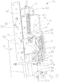
- a machine 50 or device comprising the blade 10 previously described, capable of performing the cut and the connection between the rootstock and the scion.
- the machine 50 comprises:
- the base 54 of the frame 52 preferably, comprises a cushion 56 to facilitate the positioning of the material to be processed, the scion and the rootstock, not shown in the figure, which are to be cut and joined.
- the machine 50 can be mounted on a fixed support, for example a work platform, not shown in the figure.
- the frame 52 surrounds and guides the movable carriage 60, in cooperation with a guide column 58, as indicated in figure 12 .
- the movable carriage 60 is preferably a block having a parallelepiped shape.
- a locating mechanism 61 can preferably be associated to the frame 52 near the upper end of the movable carriage 60, to sense when the movable carriage 60 reaches its top rest position, as is shown in figure 12 , so as to activate a corresponding ejection means to clean the base from the waste material, for example a jet of compressed air near the base 54, not shown in the figure.
- the blade 10 is associated to the movable carriage 60 with its cutting edge 16 facing the base 54. A downward movement of the movable carriage 60 thus enables the blade 10 to meet the base 54 to thereby perform the cut required for grafting.
- first side 52A shown in figures 12 and 13
- second side 52B is defined, opposite to the first side 52A, and not shown in the figures.
- the seat 64 of the movable carriage 60 is formed so as to guide the extractor 66 along said cutting axis X-X.
- the extractor 66 is movably associated to the movable carriage 60 and interposed between said carriage and the blade.
- it includes a head 67 that protrudes from said seat 64 and a pair of teeth 68 that extend longitudinally in the direction of said axis X-X so as to be inserted into the inlets of the contoured portion of the blade 10.
- the extractor 66 is shown detached, the same extractor 66 is in contact with the rear side of the blade 10 and with at least the side of the rectangular seat 64 opposite the blade 10.
- the frame 52 also has connected to it a fixed abutment 70 that extends horizontally toward the blade 10 and is provided with teeth 72 that surround the contoured portion of the same, but without touching the blade 10 itself.
- the fixed abutment is connected to the frame on its first side 52A.
- the fixed abutment 70 has its lower edge arranged at a distance from the base 54 that is slightly smaller than the distance of the cutting edge 16 of the blade 10 when the blade is in a fully raised or idle position, as shown in the figure.
- the bottom end of the extractor 66 is preferably at the same level as the lower edge of the fixed abutment 70.
- a selecting cam 74 comprises an upper part having substantially the shape of a W hinged by means of a pin 76 to the frame 52, preferably in contact in a manner to maintain its position by friction, for example with friction washers or other means, and an elongate lower part provided with an end-stop 78, suitable to abut against the head 67 of the extractor 66, as described hereinbelow.
- the selecting cam 74 is hinged to the first side 52A of the frame 52.
- the upper part of the selecting cam 74 comprises a symmetrical cam profile. Only half of the profile will be described below, as the other half profile is symmetrical with respect to the pin 76.
- the half cam profile comprises a downward tract 75 that ends with a groove 77 and a wall 79, as shown in figure 12 .
- An arm 80 is hinged by means of a shoulder 81 to the upper end of the movable carriage 60, and the arm has however the capability of sliding inside the shoulder 81.
- a roller 82 is hinged to the free end of the arm 80, opposite said shoulder, and is pushed toward the selecting cam 74 by a spring 84. When the movable carriage 60 is driven downward, the roller 82 comes into contact with one of the half profiles of the upper part of the selecting cam 74.
- the selecting cam 74 can move to two angular positions with respect to the first side 52A of the frame 52, as shown by the twin arrows shown respectively in figure 12 and 13 .
- the two angular positions of the selecting cam 74 are selected by means of the downward tract of the arm 80 whose roller 82 comes into contact with the cam profile.
- the roller 82 can move down and engage the downward tract 75 until it reaches the groove 77, where it pushes against the wall 79.
- This push induces the selecting cam 74 to rotate about its pin 76 so as to assume the other angular position, shown respectively in figure 13 , that is, the position in which its end-stop 78 is moved away from the longitudinal cutting axis X-X of the blade 10.
- the end-stop 78 can be positioned above the head 67 of the extractor 66, as is shown in figure 12 , or it can be moved away from the head 67 of the extractor 66 as shown in figure 13 , thus allowing the extractor 66 to move up, as is described below and shown conveniently in figure 13 .
- Figure 14A illustrates the respective positions of the end-stop 78 and of the head 67 of the extractor 66, when the selecting cam 74 is disposed in the angular position shown in figure 12 .
- the end-stop 78 thrusts against the head 67 thanks to the above-mentioned angular movement of the cam 74, which moves to the position corresponding with the X-X cutting axis.
- the lower end of the extractor 66 is at the same level as the lower edge of the fixed abutment 70.
- the movable carriage 60 is moved vertically by appropriate drive means.
- These drive means can be manual, for example through a pedal pushed by an operator for its downward movement and by return springs to return it to a raised position, or they can be semiautomatic, for example by connecting respectively the movable carriage 60 and the frame 52 to the two operating ends of a linear actuator. An operator will then be able to control the operation of the linear actuator.
- the motion of the movable carriage 60 can also be automatic, that is, driven by a predetermined processing cycle and operated by an automatic machine.
- the operator is preferably seated in front of the device 50, that is, on the right of the device shown in figure 12 and, for convenience, reference will be made, respectively, to the left side of the blade or to the right side of the blade indicating the side of the blade that is on the first side 52A or on the second side 52B of the frame 52 of the machine 50, as they were previously described.
- the side of the blade considered below in each case is described by way of example but without limitations.
- the operator will check that the selecting cam 74 is in the angular position in which it holds the end-stop 78 positioned above the head 67 of the extractor 66, as shown in figures 12 , 14A and 15 .
- a first material for example a bud or scion 11, is then inserted from the first side 52A, positioning the latter on the cushion 56 of the base 54, in such a manner as to have the scion 11 turned toward the right side of the blade 10, that is on the second side 52B opposite the first side 52A.
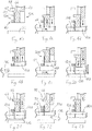
- the pedal-operated mechanism or linear actuator of the device is now actuated to perform a first cutting stroke in which the movable carriage 60 moves downward, as is shown in figure 16 along the longitudinal cutting axis X-X, thus bringing the blade 10 and the extractor 66 to abut against the scion 11.
- the end-stop 78 of the cam 74 is moved away from the longitudinal axis X-X.
- the movable carriage 60 pushes the blade 10 through the scion 11, dividing it into a useful part 11 A and a waste part 11 B, while the extractor 66 remains in abutment on the same useful part 11 A, being able to move with respect to the movable carriage 60, as previously described.
- the extractor 66 also moves up, being supported from below thanks also to the useful part 11 A.
- the waste part 11 B on the left side of the blade 10 becomes detached from the useful part 11 A, while the latter, having no hindrances on that side, remains restrained by the bar 10. It should be noted that the detachment comes about because the thrust exerted by the upward moving carriage is such as to overcome the frictional resistance between the contoured portion 14 of the blade 10 and the vegetal material trapped there. In fact, the vegetal material has a certain roughness and springiness so that, once cut, it tends to expand and becomes stuck in said inlets of the blade.
- the extractor 66 resting on the useful part 11 A of the scion 11, will have its head 67 higher than the blade 10, thus allowing the useful part 11 A to remain attached to the blade 10.
- the device is now actuated for a second cutting stroke, as seen previously, during which the blade 10 penetrates through the rootstock 13 until it reaches the cushion 56, thus cutting the rootstock 13 into a useful part 13A and a waste part 13B.
- the useful part 11A of the scion previously held back by the blade 10 is pushed upward by the waste part 13B, so that the latter takes its place.
- the extractor 66 is also moved a further distance upward from the cutting edge of the blade 10.
- the blade 10 continues to move upward, away from the base 54.
- the useful part 13A of the rootstock follows this movement upward until it reaches the height of the fixed abutment 70.
- the waste part 13B of the rootstock slips off from the blade 10 and falls on the right side of the blade and, consequently, the useful part 11 A of the scion also slips off from the blade thanks to the stroke against the extractor 66, until it ends up substantially aligned horizontally with the useful part 13A of the rootstock on the right side of the contoured blade 10.
- the end-stop 78 keeps the extractor 66 locked in position, so that its lower end is substantially orizzontally aligned with the lower edge of the fixed abutment 70, as shown in figure 22 .
- the substantially aligned position of the useful part 13A and of the useful part 11 A, of the rootstock and the scion respectively, means that the contoured cut of the useful part 11 A of the scion is now engaged in the respective contoured corresponding cut of the useful part 13A of the rootstock, unless the blade 10 is still interposed between the two contoured cuts.
- the device 50 is provided with an ejection mechanism 61 as described above, for example one operated by compressed air, this facilitates the removal of the waste part 11 B and of the waste part 13B, of the scion and the rootstock respectively, when these elements are detached or removed from the blade 10.
- the operator is spared the time and the attention necessary for removing any waste parts that remain on the cushion 56 or on the base 54, for example by operating a jet of compressed air or other ejection means, which is preferably actuated when the movable carriage 60 reaches it upper rest position.
- the scion 11 and the rootstock 13 can be positioned alternately and the movable carriage 60 can be operated as described above.
- a blade according to the invention can also be used with a manual grafting device of prior-art type, for example such as found in US7451544 , in which a gripper includes two hinged graspable ends, that can be moved directly by the hand of an operator.
- a first graspable end is integral to a movable blade-support carriage and a second graspable end is integral to a base and to an abut that surrounds the blade.
- the two graspable ends After having set down the material, that is, the scion or the rootstock, on the base, the two graspable ends are moved close to each other with the hand to move the blade against the base and thus perform the cut on the material. After this, when the two graspable ends are released they are free to move away, and consequently the blade moves away from the base. The abut surrounding the blade prevents the material from following the blade as the blade moves away from the base. The material is thus freed from the blade and the operator can perform another cut on another material.
- a blade according to the invention can also be used by means of another machine such as the one disclosed in EP1566093 in paragraphs from [0136] to [0151].
- an automatic system for example pneumatic or hydraulic, is used to drive the different components of the machine that perform the cut in two different work positions.
- a first work position is dedicated to a first step in which the scion is cut, holding the useful half with the blade and releasing the waste part.
- a second operating position is dedicated to a second step, in which the blade that held the useful part of the scion cuts the rootstock and in which afterward the waste part of the rootstock is discarded and the useful part of the scion and the useful part of the rootstock are aligned.
- .Two stations similar to each other, are arranged in a specular manner at the respective ends of a power-driven carousel, and each occupies one of the work positions, so that with one 180-degree rotation of the rotating carousel they swap their position to work each time on the respective material which is brought to them by suitable automatic feeding means.
- one station is first arranged in the first work position, where it receives a scion and cuts it, holds the respective useful part, and then moves, thanks to the 180-degree rotation of the rotating carousel, to the second work position where it receives a rootstock that it can cut it, discarding the respective waste part, and grafts it with the useful part of the scion.
- Automated feeding means are present for grasping the scion and rootstock and then positioning them respectively in the corresponding work positions where the two said stations are supplied.
- this machine is not provided with a fixed abut, as previously described, but the swap is carried out at the second work position, moving simultaneously a base (matrix 109 in EP1566093 ) into contact with the waste part of the rootstock and an extractor (the thruster 111 in EP1566093 ) into contact with the useful part of the scion.
- This simultaneous movement of the base and the extractor is possible, since the rootstock feeding means, an automated gripper, keeps the useful part of the rootstock in a substantially fixed position so that the scion can be pushed by the extractor.
- the gripper remaining fixed in position, holds steady the useful part of the rootstock, which becomes detached from the waste half of the same, achieving subsequently the mating of the useful part of the scion with the useful part of the rootstock.
- This machine or device comprises:
- Each of said two grafting units comprises in turn:
- a further objective of the present invention is a method for grafting plants comprising the following steps:
- the cutting steps on the first and second material are performed so that at least two protrusions are of substantially similar size.
- the cutting steps on the first and second material are performed so that said at least two protrusions are different in size.
- the method is carried out with the blade and the procedure as previously described.
- Another objective of the invention is to provide a plant having a grafted portion achieved with the use of a blade and a device as previously described.
- the plant includes a grafting contour forming on the circumference of the plant at least four lobes or inlets between a rootstock portion and a scion portion.
- the cut made with a blade and/or a device according to the invention makes it substantially possible to leave, between the scion and the rootstock, a minimum space resulting from the thickness of the blade.
- This space is useful to favour the growth of new cells forming on the exchange surface to originate optimum healing.
- the space will be restricted because, on one hand, the blade is thin, and on the other hand, as previously mentioned, the cut material has a degree of springiness and, therefore, it tends to expand after being cut.
- an excessively tight graft for example as with the machine previously described in paragraph [0011], could not favour the new cells that are expected to form on the exchange surface.
- a blade and/or a device according to the invention makes it possible to achieve a stronger rootstock/scion graft than can be obtained with the prior art, precisely because the contoured grafting that is achieved extends over a wide surface so that the contact surface between the parts being grafted is increased. Consequently, the result is a firmer graft.
- a blade and/or a device according to the invention performs a substantially cold cut, without causing burns and/or scorches, safeguarding the living cells that afterward are in better condition for the healing process.
- contoured graft achieved with a blade and/or a device according to the invention also makes it possible to have a graft with more than one graft holding plane, for example two or three holding planes for the graft, as previously described, so that the stability and firmness of the graft is further improved, in addition to further increasing the exchange surface.
- a blade similar to the blade 10 can have the two extremal points arranged at a different distance from the first plane, so as to have more holding planes, similarly to the blades 310 and 410.
Landscapes
- Life Sciences & Earth Sciences (AREA)
- Botany (AREA)
- Developmental Biology & Embryology (AREA)
- Environmental Sciences (AREA)
- Cultivation Of Plants (AREA)
- Perforating, Stamping-Out Or Severing By Means Other Than Cutting (AREA)
Applications Claiming Priority (1)
| Application Number | Priority Date | Filing Date | Title |
|---|---|---|---|
| ITUB2016A000883A ITUB20160883A1 (it) | 2016-02-19 | 2016-02-19 | Lama di taglio per innesti di piante, dispositivo e metodo di realizzazione di innesti di piante |
Publications (2)
| Publication Number | Publication Date |
|---|---|
| EP3207790A1 true EP3207790A1 (fr) | 2017-08-23 |
| EP3207790B1 EP3207790B1 (fr) | 2019-07-24 |
Family
ID=55969389
Family Applications (1)
| Application Number | Title | Priority Date | Filing Date |
|---|---|---|---|
| EP17156092.3A Active EP3207790B1 (fr) | 2016-02-19 | 2017-02-14 | Lame de coupe pour plantes greffées, dispositif et méthode pour plantes greffées |
Country Status (3)
| Country | Link |
|---|---|
| EP (1) | EP3207790B1 (fr) |
| ES (1) | ES2750793T3 (fr) |
| IT (1) | ITUB20160883A1 (fr) |
Cited By (4)
| Publication number | Priority date | Publication date | Assignee | Title |
|---|---|---|---|---|
| IT201800003602A1 (it) * | 2018-03-15 | 2018-06-15 | Romano Appiano | Lama di taglio per innesti di piante |
| CN112544262A (zh) * | 2020-11-06 | 2021-03-26 | 苏州永乐生物科技有限公司 | 一种果树林木的嫁接方法 |
| CN112997712A (zh) * | 2021-03-12 | 2021-06-22 | 宁夏农林科学院荒漠化治理研究所(宁夏防沙治沙与水土保持重点实验室) | 一种观赏桃树嫁接装置 |
| CN113875416A (zh) * | 2021-11-15 | 2022-01-04 | 江西省永盛园艺股份有限公司 | 一种花卉苗木培育用辅助嫁接装置 |
Citations (8)
| Publication number | Priority date | Publication date | Assignee | Title |
|---|---|---|---|---|
| US713949A (en) * | 1902-03-24 | 1902-11-18 | James Birney Burrell | Grafting. |
| FR2541562A1 (fr) | 1983-02-25 | 1984-08-31 | Mecanique Gle Mailletaise | Procede de greffage automatique de la vigne et machine comportant application de ce procede |
| FR2555403A2 (fr) * | 1983-02-25 | 1985-05-31 | Mecanique Gle Mailletaise | Procede et machine de greffage automatique, notamment de la vigne |
| CN85105012A (zh) * | 1985-07-02 | 1986-12-31 | 林锦耀 | 嫁接刀 |
| SU1665949A1 (ru) * | 1989-03-10 | 1991-07-30 | Крымское Научно-Производственное Объединение "Плодмашпроект" | Способ прививки растений и устройство дл его осуществлени |
| WO1995015078A2 (fr) * | 1993-12-03 | 1995-06-08 | World Wide Product Development Co. Ltd. | Outil de coupe |
| EP1566093A1 (fr) | 2004-02-20 | 2005-08-24 | D'andrea Giancarlo (Ditta Individuale) | Appareil à greffage pour les boutures de vignes ou autres variétés de légumes et un méthode de greffage |
| US7451544B1 (en) | 2005-02-10 | 2008-11-18 | Ho Cheng Garden Tools Co., Ltd. | Gardening shears having double functions |
Family Cites Families (1)
| Publication number | Priority date | Publication date | Assignee | Title |
|---|---|---|---|---|
| FR2539951B1 (fr) * | 1983-02-02 | 1987-09-18 | Egretier Cie Sa | Machine a greffer |
-
2016
- 2016-02-19 IT ITUB2016A000883A patent/ITUB20160883A1/it unknown
-
2017
- 2017-02-14 ES ES17156092T patent/ES2750793T3/es active Active
- 2017-02-14 EP EP17156092.3A patent/EP3207790B1/fr active Active
Patent Citations (8)
| Publication number | Priority date | Publication date | Assignee | Title |
|---|---|---|---|---|
| US713949A (en) * | 1902-03-24 | 1902-11-18 | James Birney Burrell | Grafting. |
| FR2541562A1 (fr) | 1983-02-25 | 1984-08-31 | Mecanique Gle Mailletaise | Procede de greffage automatique de la vigne et machine comportant application de ce procede |
| FR2555403A2 (fr) * | 1983-02-25 | 1985-05-31 | Mecanique Gle Mailletaise | Procede et machine de greffage automatique, notamment de la vigne |
| CN85105012A (zh) * | 1985-07-02 | 1986-12-31 | 林锦耀 | 嫁接刀 |
| SU1665949A1 (ru) * | 1989-03-10 | 1991-07-30 | Крымское Научно-Производственное Объединение "Плодмашпроект" | Способ прививки растений и устройство дл его осуществлени |
| WO1995015078A2 (fr) * | 1993-12-03 | 1995-06-08 | World Wide Product Development Co. Ltd. | Outil de coupe |
| EP1566093A1 (fr) | 2004-02-20 | 2005-08-24 | D'andrea Giancarlo (Ditta Individuale) | Appareil à greffage pour les boutures de vignes ou autres variétés de légumes et un méthode de greffage |
| US7451544B1 (en) | 2005-02-10 | 2008-11-18 | Ho Cheng Garden Tools Co., Ltd. | Gardening shears having double functions |
Cited By (5)
| Publication number | Priority date | Publication date | Assignee | Title |
|---|---|---|---|---|
| IT201800003602A1 (it) * | 2018-03-15 | 2018-06-15 | Romano Appiano | Lama di taglio per innesti di piante |
| CN112544262A (zh) * | 2020-11-06 | 2021-03-26 | 苏州永乐生物科技有限公司 | 一种果树林木的嫁接方法 |
| CN112997712A (zh) * | 2021-03-12 | 2021-06-22 | 宁夏农林科学院荒漠化治理研究所(宁夏防沙治沙与水土保持重点实验室) | 一种观赏桃树嫁接装置 |
| CN112997712B (zh) * | 2021-03-12 | 2023-03-14 | 宁夏农林科学院荒漠化治理研究所(宁夏防沙治沙与水土保持重点实验室) | 一种观赏桃树嫁接装置 |
| CN113875416A (zh) * | 2021-11-15 | 2022-01-04 | 江西省永盛园艺股份有限公司 | 一种花卉苗木培育用辅助嫁接装置 |
Also Published As
| Publication number | Publication date |
|---|---|
| ITUB20160883A1 (it) | 2017-08-19 |
| EP3207790B1 (fr) | 2019-07-24 |
| ES2750793T3 (es) | 2020-03-27 |
Similar Documents
| Publication | Publication Date | Title |
|---|---|---|
| EP3207790B1 (fr) | Lame de coupe pour plantes greffées, dispositif et méthode pour plantes greffées | |
| CN113243218B (zh) | 一种茄果蔬菜劈接嫁接装置 | |
| CN106856830A (zh) | 菠萝剪切与采摘装置 | |
| JP2017055731A (ja) | 接ぎ木装置 | |
| CN105660205A (zh) | 一种成组式斜插嫁接机 | |
| AU2020100636A4 (en) | Grafting Jig | |
| CN106717536B (zh) | 桑叶、艾叶、银杏叶快速采集器 | |
| US4392304A (en) | Universal manual grafting device | |
| CN120113490B (zh) | 一种嫁接设备 | |
| EP3571923B1 (fr) | Tête d'outil et utilisation de la tête d'outil et procédé de régulation de la croissance des pousses supérieures d'un arbre | |
| KR101339631B1 (ko) | 과수가지 아상 작업기능을 구비한 전정 가위 | |
| EP1442655B1 (fr) | Dispositif pour planter des boutures | |
| CN215122748U (zh) | 一种羊肚菌养殖用采摘装置 | |
| EP2161982B1 (fr) | Procédé et machine pour greffer des boutures de vigne et porte-greffe de variétés de plante analogues | |
| CN214628274U (zh) | 一种多工位硬枝苗木自动化嫁接装置 | |
| CN210445623U (zh) | 一种无土栽培蔬菜半自动根茎分段设备 | |
| CN2491201Y (zh) | 接穗砧木切削机 | |
| CN118402388B (zh) | 一种用于茶树嫁接的接穗削面装置 | |
| CN120113491B (zh) | 一种末端执行器 | |
| CN2862660Y (zh) | 一种蔬菜嫁接工具 | |
| CN222755521U (zh) | 一种花卉铡根装置 | |
| CN219543519U (zh) | 一种竹家具制品生产用分选设备 | |
| KR200474257Y1 (ko) | 속과기 | |
| Williams et al. | The barracuda: A novel cutting mechanism for pruning canes wrapped around wires | |
| GB2247601A (en) | Cutting apparatus and methods for use in micropropagation. |
Legal Events
| Date | Code | Title | Description |
|---|---|---|---|
| PUAI | Public reference made under article 153(3) epc to a published international application that has entered the european phase |
Free format text: ORIGINAL CODE: 0009012 |
|
| STAA | Information on the status of an ep patent application or granted ep patent |
Free format text: STATUS: THE APPLICATION HAS BEEN PUBLISHED |
|
| AK | Designated contracting states |
Kind code of ref document: A1 Designated state(s): AL AT BE BG CH CY CZ DE DK EE ES FI FR GB GR HR HU IE IS IT LI LT LU LV MC MK MT NL NO PL PT RO RS SE SI SK SM TR |
|
| AX | Request for extension of the european patent |
Extension state: BA ME |
|
| STAA | Information on the status of an ep patent application or granted ep patent |
Free format text: STATUS: REQUEST FOR EXAMINATION WAS MADE |
|
| 17P | Request for examination filed |
Effective date: 20180125 |
|
| RBV | Designated contracting states (corrected) |
Designated state(s): AL AT BE BG CH CY CZ DE DK EE ES FI FR GB GR HR HU IE IS IT LI LT LU LV MC MK MT NL NO PL PT RO RS SE SI SK SM TR |
|
| STAA | Information on the status of an ep patent application or granted ep patent |
Free format text: STATUS: EXAMINATION IS IN PROGRESS |
|
| 17Q | First examination report despatched |
Effective date: 20180605 |
|
| REG | Reference to a national code |
Ref country code: DE Ref legal event code: R079 Ref document number: 602017005403 Country of ref document: DE Free format text: PREVIOUS MAIN CLASS: A01G0001060000 Ipc: A01G0002300000 |
|
| GRAP | Despatch of communication of intention to grant a patent |
Free format text: ORIGINAL CODE: EPIDOSNIGR1 |
|
| STAA | Information on the status of an ep patent application or granted ep patent |
Free format text: STATUS: GRANT OF PATENT IS INTENDED |
|
| RIC1 | Information provided on ipc code assigned before grant |
Ipc: A01G 2/30 20180101AFI20190214BHEP Ipc: A01G 2/35 20180101ALI20190214BHEP |
|
| INTG | Intention to grant announced |
Effective date: 20190304 |
|
| GRAS | Grant fee paid |
Free format text: ORIGINAL CODE: EPIDOSNIGR3 |
|
| GRAA | (expected) grant |
Free format text: ORIGINAL CODE: 0009210 |
|
| STAA | Information on the status of an ep patent application or granted ep patent |
Free format text: STATUS: THE PATENT HAS BEEN GRANTED |
|
| AK | Designated contracting states |
Kind code of ref document: B1 Designated state(s): AL AT BE BG CH CY CZ DE DK EE ES FI FR GB GR HR HU IE IS IT LI LT LU LV MC MK MT NL NO PL PT RO RS SE SI SK SM TR |
|
| REG | Reference to a national code |
Ref country code: GB Ref legal event code: FG4D |
|
| REG | Reference to a national code |
Ref country code: CH Ref legal event code: EP |
|
| REG | Reference to a national code |
Ref country code: DE Ref legal event code: R096 Ref document number: 602017005403 Country of ref document: DE |
|
| REG | Reference to a national code |
Ref country code: AT Ref legal event code: REF Ref document number: 1157065 Country of ref document: AT Kind code of ref document: T Effective date: 20190815 |
|
| REG | Reference to a national code |
Ref country code: IE Ref legal event code: FG4D |
|
| REG | Reference to a national code |
Ref country code: NL Ref legal event code: MP Effective date: 20190724 |
|
| REG | Reference to a national code |
Ref country code: LT Ref legal event code: MG4D |
|
| REG | Reference to a national code |
Ref country code: AT Ref legal event code: MK05 Ref document number: 1157065 Country of ref document: AT Kind code of ref document: T Effective date: 20190724 |
|
| PG25 | Lapsed in a contracting state [announced via postgrant information from national office to epo] |
Ref country code: LT Free format text: LAPSE BECAUSE OF FAILURE TO SUBMIT A TRANSLATION OF THE DESCRIPTION OR TO PAY THE FEE WITHIN THE PRESCRIBED TIME-LIMIT Effective date: 20190724 Ref country code: SE Free format text: LAPSE BECAUSE OF FAILURE TO SUBMIT A TRANSLATION OF THE DESCRIPTION OR TO PAY THE FEE WITHIN THE PRESCRIBED TIME-LIMIT Effective date: 20190724 Ref country code: BG Free format text: LAPSE BECAUSE OF FAILURE TO SUBMIT A TRANSLATION OF THE DESCRIPTION OR TO PAY THE FEE WITHIN THE PRESCRIBED TIME-LIMIT Effective date: 20191024 Ref country code: AT Free format text: LAPSE BECAUSE OF FAILURE TO SUBMIT A TRANSLATION OF THE DESCRIPTION OR TO PAY THE FEE WITHIN THE PRESCRIBED TIME-LIMIT Effective date: 20190724 Ref country code: NO Free format text: LAPSE BECAUSE OF FAILURE TO SUBMIT A TRANSLATION OF THE DESCRIPTION OR TO PAY THE FEE WITHIN THE PRESCRIBED TIME-LIMIT Effective date: 20191024 Ref country code: NL Free format text: LAPSE BECAUSE OF FAILURE TO SUBMIT A TRANSLATION OF THE DESCRIPTION OR TO PAY THE FEE WITHIN THE PRESCRIBED TIME-LIMIT Effective date: 20190724 Ref country code: PT Free format text: LAPSE BECAUSE OF FAILURE TO SUBMIT A TRANSLATION OF THE DESCRIPTION OR TO PAY THE FEE WITHIN THE PRESCRIBED TIME-LIMIT Effective date: 20191125 Ref country code: HR Free format text: LAPSE BECAUSE OF FAILURE TO SUBMIT A TRANSLATION OF THE DESCRIPTION OR TO PAY THE FEE WITHIN THE PRESCRIBED TIME-LIMIT Effective date: 20190724 Ref country code: FI Free format text: LAPSE BECAUSE OF FAILURE TO SUBMIT A TRANSLATION OF THE DESCRIPTION OR TO PAY THE FEE WITHIN THE PRESCRIBED TIME-LIMIT Effective date: 20190724 |
|
| PG25 | Lapsed in a contracting state [announced via postgrant information from national office to epo] |
Ref country code: LV Free format text: LAPSE BECAUSE OF FAILURE TO SUBMIT A TRANSLATION OF THE DESCRIPTION OR TO PAY THE FEE WITHIN THE PRESCRIBED TIME-LIMIT Effective date: 20190724 Ref country code: GR Free format text: LAPSE BECAUSE OF FAILURE TO SUBMIT A TRANSLATION OF THE DESCRIPTION OR TO PAY THE FEE WITHIN THE PRESCRIBED TIME-LIMIT Effective date: 20191025 Ref country code: RS Free format text: LAPSE BECAUSE OF FAILURE TO SUBMIT A TRANSLATION OF THE DESCRIPTION OR TO PAY THE FEE WITHIN THE PRESCRIBED TIME-LIMIT Effective date: 20190724 Ref country code: IS Free format text: LAPSE BECAUSE OF FAILURE TO SUBMIT A TRANSLATION OF THE DESCRIPTION OR TO PAY THE FEE WITHIN THE PRESCRIBED TIME-LIMIT Effective date: 20191124 Ref country code: AL Free format text: LAPSE BECAUSE OF FAILURE TO SUBMIT A TRANSLATION OF THE DESCRIPTION OR TO PAY THE FEE WITHIN THE PRESCRIBED TIME-LIMIT Effective date: 20190724 |
|
| REG | Reference to a national code |
Ref country code: ES Ref legal event code: FG2A Ref document number: 2750793 Country of ref document: ES Kind code of ref document: T3 Effective date: 20200327 |
|
| PG25 | Lapsed in a contracting state [announced via postgrant information from national office to epo] |
Ref country code: TR Free format text: LAPSE BECAUSE OF FAILURE TO SUBMIT A TRANSLATION OF THE DESCRIPTION OR TO PAY THE FEE WITHIN THE PRESCRIBED TIME-LIMIT Effective date: 20190724 |
|
| PG25 | Lapsed in a contracting state [announced via postgrant information from national office to epo] |
Ref country code: RO Free format text: LAPSE BECAUSE OF FAILURE TO SUBMIT A TRANSLATION OF THE DESCRIPTION OR TO PAY THE FEE WITHIN THE PRESCRIBED TIME-LIMIT Effective date: 20190724 Ref country code: DK Free format text: LAPSE BECAUSE OF FAILURE TO SUBMIT A TRANSLATION OF THE DESCRIPTION OR TO PAY THE FEE WITHIN THE PRESCRIBED TIME-LIMIT Effective date: 20190724 Ref country code: EE Free format text: LAPSE BECAUSE OF FAILURE TO SUBMIT A TRANSLATION OF THE DESCRIPTION OR TO PAY THE FEE WITHIN THE PRESCRIBED TIME-LIMIT Effective date: 20190724 Ref country code: PL Free format text: LAPSE BECAUSE OF FAILURE TO SUBMIT A TRANSLATION OF THE DESCRIPTION OR TO PAY THE FEE WITHIN THE PRESCRIBED TIME-LIMIT Effective date: 20190724 |
|
| PG25 | Lapsed in a contracting state [announced via postgrant information from national office to epo] |
Ref country code: SK Free format text: LAPSE BECAUSE OF FAILURE TO SUBMIT A TRANSLATION OF THE DESCRIPTION OR TO PAY THE FEE WITHIN THE PRESCRIBED TIME-LIMIT Effective date: 20190724 Ref country code: IS Free format text: LAPSE BECAUSE OF FAILURE TO SUBMIT A TRANSLATION OF THE DESCRIPTION OR TO PAY THE FEE WITHIN THE PRESCRIBED TIME-LIMIT Effective date: 20200224 Ref country code: SM Free format text: LAPSE BECAUSE OF FAILURE TO SUBMIT A TRANSLATION OF THE DESCRIPTION OR TO PAY THE FEE WITHIN THE PRESCRIBED TIME-LIMIT Effective date: 20190724 Ref country code: CZ Free format text: LAPSE BECAUSE OF FAILURE TO SUBMIT A TRANSLATION OF THE DESCRIPTION OR TO PAY THE FEE WITHIN THE PRESCRIBED TIME-LIMIT Effective date: 20190724 |
|
| REG | Reference to a national code |
Ref country code: DE Ref legal event code: R097 Ref document number: 602017005403 Country of ref document: DE |
|
| PLBE | No opposition filed within time limit |
Free format text: ORIGINAL CODE: 0009261 |
|
| STAA | Information on the status of an ep patent application or granted ep patent |
Free format text: STATUS: NO OPPOSITION FILED WITHIN TIME LIMIT |
|
| PG2D | Information on lapse in contracting state deleted |
Ref country code: IS |
|
| 26N | No opposition filed |
Effective date: 20200603 |
|
| PG25 | Lapsed in a contracting state [announced via postgrant information from national office to epo] |
Ref country code: SI Free format text: LAPSE BECAUSE OF FAILURE TO SUBMIT A TRANSLATION OF THE DESCRIPTION OR TO PAY THE FEE WITHIN THE PRESCRIBED TIME-LIMIT Effective date: 20190724 |
|
| REG | Reference to a national code |
Ref country code: CH Ref legal event code: PL |
|
| REG | Reference to a national code |
Ref country code: BE Ref legal event code: MM Effective date: 20200229 |
|
| PG25 | Lapsed in a contracting state [announced via postgrant information from national office to epo] |
Ref country code: LU Free format text: LAPSE BECAUSE OF NON-PAYMENT OF DUE FEES Effective date: 20200214 Ref country code: MC Free format text: LAPSE BECAUSE OF FAILURE TO SUBMIT A TRANSLATION OF THE DESCRIPTION OR TO PAY THE FEE WITHIN THE PRESCRIBED TIME-LIMIT Effective date: 20190724 |
|
| PG25 | Lapsed in a contracting state [announced via postgrant information from national office to epo] |
Ref country code: LI Free format text: LAPSE BECAUSE OF NON-PAYMENT OF DUE FEES Effective date: 20200229 Ref country code: CH Free format text: LAPSE BECAUSE OF NON-PAYMENT OF DUE FEES Effective date: 20200229 |
|
| PG25 | Lapsed in a contracting state [announced via postgrant information from national office to epo] |
Ref country code: IE Free format text: LAPSE BECAUSE OF NON-PAYMENT OF DUE FEES Effective date: 20200214 |
|
| PG25 | Lapsed in a contracting state [announced via postgrant information from national office to epo] |
Ref country code: BE Free format text: LAPSE BECAUSE OF NON-PAYMENT OF DUE FEES Effective date: 20200229 |
|
| GBPC | Gb: european patent ceased through non-payment of renewal fee |
Effective date: 20210214 |
|
| PG25 | Lapsed in a contracting state [announced via postgrant information from national office to epo] |
Ref country code: GB Free format text: LAPSE BECAUSE OF NON-PAYMENT OF DUE FEES Effective date: 20210214 |
|
| PG25 | Lapsed in a contracting state [announced via postgrant information from national office to epo] |
Ref country code: MT Free format text: LAPSE BECAUSE OF FAILURE TO SUBMIT A TRANSLATION OF THE DESCRIPTION OR TO PAY THE FEE WITHIN THE PRESCRIBED TIME-LIMIT Effective date: 20190724 Ref country code: CY Free format text: LAPSE BECAUSE OF FAILURE TO SUBMIT A TRANSLATION OF THE DESCRIPTION OR TO PAY THE FEE WITHIN THE PRESCRIBED TIME-LIMIT Effective date: 20190724 |
|
| PG25 | Lapsed in a contracting state [announced via postgrant information from national office to epo] |
Ref country code: MK Free format text: LAPSE BECAUSE OF FAILURE TO SUBMIT A TRANSLATION OF THE DESCRIPTION OR TO PAY THE FEE WITHIN THE PRESCRIBED TIME-LIMIT Effective date: 20190724 |
|
| PGFP | Annual fee paid to national office [announced via postgrant information from national office to epo] |
Ref country code: FR Payment date: 20230221 Year of fee payment: 7 |
|
| PGFP | Annual fee paid to national office [announced via postgrant information from national office to epo] |
Ref country code: DE Payment date: 20230216 Year of fee payment: 7 |
|
| P01 | Opt-out of the competence of the unified patent court (upc) registered |
Effective date: 20230328 |
|
| PGFP | Annual fee paid to national office [announced via postgrant information from national office to epo] |
Ref country code: ES Payment date: 20230427 Year of fee payment: 7 |
|
| PGFP | Annual fee paid to national office [announced via postgrant information from national office to epo] |
Ref country code: IT Payment date: 20240131 Year of fee payment: 8 |
|
| REG | Reference to a national code |
Ref country code: DE Ref legal event code: R119 Ref document number: 602017005403 Country of ref document: DE |
|
| PG25 | Lapsed in a contracting state [announced via postgrant information from national office to epo] |
Ref country code: DE Free format text: LAPSE BECAUSE OF NON-PAYMENT OF DUE FEES Effective date: 20240903 |
|
| PG25 | Lapsed in a contracting state [announced via postgrant information from national office to epo] |
Ref country code: FR Free format text: LAPSE BECAUSE OF NON-PAYMENT OF DUE FEES Effective date: 20240229 |
|
| PG25 | Lapsed in a contracting state [announced via postgrant information from national office to epo] |
Ref country code: FR Free format text: LAPSE BECAUSE OF NON-PAYMENT OF DUE FEES Effective date: 20240229 Ref country code: DE Free format text: LAPSE BECAUSE OF NON-PAYMENT OF DUE FEES Effective date: 20240903 |
|
| REG | Reference to a national code |
Ref country code: ES Ref legal event code: FD2A Effective date: 20250331 |
|
| PG25 | Lapsed in a contracting state [announced via postgrant information from national office to epo] |
Ref country code: ES Free format text: LAPSE BECAUSE OF NON-PAYMENT OF DUE FEES Effective date: 20240215 |
|
| PG25 | Lapsed in a contracting state [announced via postgrant information from national office to epo] |
Ref country code: IT Free format text: LAPSE BECAUSE OF NON-PAYMENT OF DUE FEES Effective date: 20250214 |