EP3207792A1 - Dispositif de fabrication de beurre - Google Patents
Dispositif de fabrication de beurre Download PDFInfo
- Publication number
- EP3207792A1 EP3207792A1 EP17154347.3A EP17154347A EP3207792A1 EP 3207792 A1 EP3207792 A1 EP 3207792A1 EP 17154347 A EP17154347 A EP 17154347A EP 3207792 A1 EP3207792 A1 EP 3207792A1
- Authority
- EP
- European Patent Office
- Prior art keywords
- viewing window
- sight glass
- butter
- nozzle
- passages
- Prior art date
- Legal status (The legal status is an assumption and is not a legal conclusion. Google has not performed a legal analysis and makes no representation as to the accuracy of the status listed.)
- Withdrawn
Links
- 235000014121 butter Nutrition 0.000 title claims abstract description 45
- 239000011521 glass Substances 0.000 claims abstract description 54
- 238000010438 heat treatment Methods 0.000 claims abstract description 23
- 239000012530 fluid Substances 0.000 claims description 11
- 241000792859 Enema Species 0.000 claims description 2
- 239000007920 enema Substances 0.000 claims description 2
- 229940095399 enema Drugs 0.000 claims description 2
- 239000004020 conductor Substances 0.000 claims 1
- 235000020247 cow milk Nutrition 0.000 claims 1
- 239000000155 melt Substances 0.000 claims 1
- 238000000034 method Methods 0.000 description 16
- XLYOFNOQVPJJNP-UHFFFAOYSA-N water Substances O XLYOFNOQVPJJNP-UHFFFAOYSA-N 0.000 description 6
- 238000004519 manufacturing process Methods 0.000 description 5
- 230000015572 biosynthetic process Effects 0.000 description 4
- 239000005862 Whey Substances 0.000 description 3
- 102000007544 Whey Proteins Human genes 0.000 description 3
- 108010046377 Whey Proteins Proteins 0.000 description 3
- 239000002253 acid Substances 0.000 description 3
- 239000000654 additive Substances 0.000 description 3
- 239000012267 brine Substances 0.000 description 3
- 239000012141 concentrate Substances 0.000 description 3
- 239000006071 cream Substances 0.000 description 3
- HPALAKNZSZLMCH-UHFFFAOYSA-M sodium;chloride;hydrate Chemical compound O.[Na+].[Cl-] HPALAKNZSZLMCH-UHFFFAOYSA-M 0.000 description 3
- 230000000007 visual effect Effects 0.000 description 3
- 235000015155 buttermilk Nutrition 0.000 description 2
- 238000004140 cleaning Methods 0.000 description 2
- 238000010276 construction Methods 0.000 description 2
- 238000001816 cooling Methods 0.000 description 2
- 238000004898 kneading Methods 0.000 description 2
- 239000000463 material Substances 0.000 description 2
- 238000010924 continuous production Methods 0.000 description 1
- 230000006735 deficit Effects 0.000 description 1
- 238000001704 evaporation Methods 0.000 description 1
- 230000008020 evaporation Effects 0.000 description 1
- 235000019197 fats Nutrition 0.000 description 1
- 239000012467 final product Substances 0.000 description 1
- 239000000796 flavoring agent Substances 0.000 description 1
- 235000019634 flavors Nutrition 0.000 description 1
- 239000013067 intermediate product Substances 0.000 description 1
- 238000005457 optimization Methods 0.000 description 1
- 238000000926 separation method Methods 0.000 description 1
- 239000007921 spray Substances 0.000 description 1
- 238000013517 stratification Methods 0.000 description 1
- 238000009827 uniform distribution Methods 0.000 description 1
- 238000007666 vacuum forming Methods 0.000 description 1
- 239000007762 w/o emulsion Substances 0.000 description 1
Images


Classifications
-
- A—HUMAN NECESSITIES
- A01—AGRICULTURE; FORESTRY; ANIMAL HUSBANDRY; HUNTING; TRAPPING; FISHING
- A01J—MANUFACTURE OF DAIRY PRODUCTS
- A01J15/00—Manufacturing butter
- A01J15/04—Rotating or oscillating churns
- A01J15/06—Rotating or oscillating churns with beating equipment which is movable in respect of the churn wall
-
- A—HUMAN NECESSITIES
- A01—AGRICULTURE; FORESTRY; ANIMAL HUSBANDRY; HUNTING; TRAPPING; FISHING
- A01J—MANUFACTURE OF DAIRY PRODUCTS
- A01J15/00—Manufacturing butter
- A01J15/10—Devices for manufacturing butter other than by churns
- A01J15/12—Devices for manufacturing butter other than by churns with arrangements for making butter in a continuous process
-
- A—HUMAN NECESSITIES
- A01—AGRICULTURE; FORESTRY; ANIMAL HUSBANDRY; HUNTING; TRAPPING; FISHING
- A01J—MANUFACTURE OF DAIRY PRODUCTS
- A01J15/00—Manufacturing butter
- A01J15/16—Details; Accessories
Definitions
- the invention describes an apparatus for producing butter according to the preamble of claim 1.
- An exemplary generic device is in the DE 10 2009 044 429 A1 described.
- Such devices For visual control of the process sequence, such devices have sight glasses in the region of a post-treatment drum and / or in the region of a vacuum-forming device in a press-off device. Due to the visual control of the process, process parameters of butter production, e.g. changed the speed of a so-called racket or settings on the presser during the procedure as needed.
- the invention therefore sets in the task of improving the observability of butter production with the generic devices.
- the invention solves the problem by a device having the features of claim 1.
- the heater it is advantageously possible that adhering to the viewing window of the sight glass butter deposits are melted so that they can drip from the sight glass. This improves the observability of the buttering process.
- the heating device is based on an electrical operating principle.
- the heating device can be easily and advantageously integrated into the viewing window of the respective sight glass.
- At least the viewing window of the heated sight glass can be acted upon in addition to the cleaning with a fluid.
- melted melted butter deposits on the lens can be additionally flushed from the lens.
- films formed in addition to the butter deposits can also be supplemented by butter additives, such as e.g. Advantageously automatically clean off additional flavors, water or whey, acid concentrates and brine on the lens.
- steam is used as the fluid, wherein the resulting condensate is trappable by means of the sight glasses or sucked by a pump and so again completely or partiallyarrangingbringbar from the Butterungslui.
- the fluid is passed through one or more nozzle-like passages on the viewing window of at least one sight glass.
- an intermediate element has the one or more nozzle-like passages.
- the fluid can be directed specifically and thus advantageously on the viewing window of the sight glass.
- the one or the plurality of nozzle-like passages is preferably arranged at an angle ⁇ of 10 to 20 °, particularly preferably 15 °, perpendicular to an axis of an opening of the intermediate element. Due to the advantageous angular position of the nozzle-like passages, a safe and thus advantageous cleaning of the viewing window of the sight glass can be realized.
- the plurality of nozzle-like passages are arranged in a parallel plane perpendicular to the axis of the opening, and preferably at an angle ⁇ of 20 to 60 °, more preferably of 30 ° to each other (fan-like) arranged. This advantageously ensures that the viewing window is cleaned particularly well.
- Fig. 1 shows a device for producing butter, hereinafter called churning machine, which has a feed 1 for cream, and a buttering cylinder 2 with a rotatably driven racket 3 for the formation of buttercorn and buttermilk from supplied cream.
- the butter kernel gets a harder consistency and can then be processed better.
- the buttercorn is then transferred via a hood 6 with a feed chute 7 in a first Abpressermatic with a presser 8.
- the Abpresser 8 converts the buttercorn into a homogeneous "water in oil emulsion" and at the same time frees the resulting Butter pattern ist of Buttermilchresten, which are subsequently removed.
- two mixing sections 9a and 9b are arranged here by way of example, in each of which a partial mass of the butter intermediate product can be processed separately.
- different butter qualities of the final product can be achieved in continuous production.
- the mixing sections 9a or 9b have at least one dosing connection 10a or 10b in each case in order to add additional flavorings, water or whey, acid concentrates and brine to the butter intermediate in a predetermined amount.
- the butter intermediate passes in the connection of each of a mixing section 9a or 9b via a vacuum chamber 11a or 11b here in a second Abpresserculture, consisting of two pressers 12a, 12b.
- the two presses of the second stage are spatially separated, with each presser 12a or 12b processing a partial mass of the butter intermediate of each mixing section 9a or 9b.
- the respective vacuum chamber 11 a, 11 b of the first Abpresserch of the respective sub-mass of the butter intermediate is withdrawn air to increase their durability and to prevent stratification by air entrapment.
- the vacuum chambers 11a, 11b each have a second sight glass 16, through which the process in the vacuum chamber is observable.
- the Butterend leave the butter machine here via spouts, which are shown in the present drawing by two mouthpieces 14a and 14b and a discharge pump 22.
- hood 6 a first sight glass 15 through which the post-buttering process in the Nachbutt fürstrommel 5 is observable.
- the first sight glass 15 has a device with which a viewing window of the first sight glass 15 can be heated (the latter not shown here).
- the heater is e.g. to be introduced into the window of the first sight glass heating element made of a material having a suitable electrical resistance, so that the viewing window is electrically heated by the heating element.
- heaters are conceivable that work with a different mode of action.
- the heating device By means of the heating device, it is advantageously possible for butter deposits forming on the first sight glass 15 to be automatically removed by the production in the butter machine, or the first sight glass 15 can be cleaned off.
- the heating device of the viewing window of the first sight glass 15 is turned on.
- the butter deposits adhering to the viewing window of the first sight glass 15 are melted, so that the butter deposits can drip off the viewing window of the first sight glass 15 into the ongoing buttering process.
- the restriction-free observation of the post-buttering process in the post-buttering drum 5 is advantageously made possible.
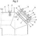
- Fig. 2 is a section of the buttering machine behind Fig. 1 in the region of a second sight glass 16 to the vacuum chamber 11 a and 11 b of the Fig. 1 shown.
- the construction of the first sight glass 15 may be designed analogously or identically to the construction of the second sight glass 16.
- the respective vacuum chamber 11a, 11b has an opening 17 in each case. Congruent with the opening 17, the vacuum chamber 11a, 11b each have a flange 18 which is fixed to the vacuum chamber 11a, b.
- the flange 18 also has an opening 19 which is contour-congruent with the opening 17 and is therefore arranged corresponding to the opening 17.
- an intermediate element 20 is arranged, which also has an opening 21. This opening 21 is designed congruent contour to the opening 17 and is therefore arranged corresponding to the opening 17.
- the intermediate element 20 has a centering projection 23, which engages in a geometrically corresponding recess 24 of the flange 18. Between the spigot 23 and the recess 24, a seal is arranged, which seals the openings 19, 21 against the environment.
- the intermediate element 20 of the second sight glass 16 has a connection 25 for a line or a hose 26. Furthermore, the intermediate element 20 of the second sight glass 16 has at least one 27 or more nozzle-like passages 27, which connects the connection 25 with the opening 21.
- the openings 21 of the three passages 27 are directed to the vacuum chamber side facing away from the intermediate element 20. Through the connection 25 and the nozzle-like passages 27, a fluid - such as steam - are passed through the intermediate member 20 into the opening 21.
- the vacuum chamber 11a, 11b (see Fig. 2 ) has a wall 35 which is provided with a passage 36. In the passage 36, a nozzle assembly 38 is used.
- a vacuum pump (not shown here) can be connected to the feedthrough 36 outside the vacuum chamber 11a, 11b, with which air and optionally steam can be sucked out of the vacuum chamber 11a, 11b.
- the nozzle assembly 38 is designed in the manner of a multiple nozzle ("spray ball-like"), the plurality of fine inlet openings with a small diameter within the vacuum chamber 11a, 11b, which open into a common channel of larger diameter, which passes through the wall 35.
- FIG. 3 and FIG. 4 in each case the intermediate element 20 with the nozzle-like passages 27 is shown.
- the here three nozzle-like passages 27 are preferably arranged at an angle ⁇ of 10 to 20 °, more preferably 15 ° perpendicular to the axis of the opening 21.
- the three passages are arranged in a plane parallel to the axis of the opening 21 preferably at an angle ⁇ of 20 to 60 °, more preferably of 30 ° to each other like a fan.
- the nozzle-like passages 27 have a diameter preferably between 1 and 5 mm, particularly preferably 1.5 mm.
- the intermediate element 20 of the first sight glass 15 can optionally also have a connection 25 and one or more nozzle-like passages 27, with which the viewing pane 29 of the first sight glass 15 can be acted upon by a fluid. This is advantageous, but not mandatory.
- the intermediate element 20 has a recess 28, in which the viewing window 29 is inserted. Between the lens 29 and the intermediate member 20, a seal 30 is arranged, which seals the opening 21 against the environment.
- the viewing window 29 and thus the second sight glass 16 has a device with which the viewing window 29 can be heated (not shown here).
- the heating device is in turn preferably in the viewing window 29 introduced heating element made of a material having a suitable electrical resistance, so that the viewing window 29 of the second sight glass 16 is electrically heated by the heating element.
- heaters are conceivable that work with a different mode of action.
- the heater it is again advantageously possible to automatically remove or clean during the butter production in the butter machine on the lens 29 of the second sight glass 16 forming butter deposits.
- the heat deposited on the lens 29 of the second sight glass 16 butter deposits are again melted with the heater so that the butter deposits from the window 29 of the second sight glass 16 can drain.
- the temperature which can be achieved during heating at the sight glass-here 16 - is preferably 40 to 90.degree. C., preferably 60.degree. A temperature above 90 ° C appears less advantageous, since evaporation of the water in the butter is not desirable.
- the viewing window 29 of the second sight glass 16 is screwed with a sight glass goggles 31 by means of several screws 32 on the intermediate member 20 and pressed.
- the sight glass goggles 31 has for this purpose a recess 33 into which the viewing window 29 engages.
- a seal 34 is arranged, which seals the visor 29 against the environment.
- the viewing window 29 of the second sight glass 16 is additionally provided with a fluid, such as e.g. Steam acted upon.
- a fluid such as e.g. Steam acted upon.
- films formed in addition to the butter deposits can also be supplemented by butter additives, such as e.g. Additional flavorings, water or whey, acid concentrates and brine on the viewing window 29 of the second sight glass 16 advantageously automatically reliably clean.
- butter additives such as e.g. Additional flavorings, water or whey, acid concentrates and brine on the viewing window 29 of the second sight glass 16 advantageously automatically reliably clean.
Landscapes
- Life Sciences & Earth Sciences (AREA)
- Animal Husbandry (AREA)
- Environmental Sciences (AREA)
- Cleaning By Liquid Or Steam (AREA)
- Dairy Products (AREA)
- Sampling And Sample Adjustment (AREA)
Applications Claiming Priority (1)
| Application Number | Priority Date | Filing Date | Title |
|---|---|---|---|
| DE202016100892.1U DE202016100892U1 (de) | 2016-02-19 | 2016-02-19 | Vorrichtung zum Herstellen von Butter |
Publications (1)
| Publication Number | Publication Date |
|---|---|
| EP3207792A1 true EP3207792A1 (fr) | 2017-08-23 |
Family
ID=55531615
Family Applications (1)
| Application Number | Title | Priority Date | Filing Date |
|---|---|---|---|
| EP17154347.3A Withdrawn EP3207792A1 (fr) | 2016-02-19 | 2017-02-02 | Dispositif de fabrication de beurre |
Country Status (3)
| Country | Link |
|---|---|
| US (1) | US20170238500A1 (fr) |
| EP (1) | EP3207792A1 (fr) |
| DE (1) | DE202016100892U1 (fr) |
Citations (3)
| Publication number | Priority date | Publication date | Assignee | Title |
|---|---|---|---|---|
| DE102005013157A1 (de) * | 2004-03-24 | 2005-12-15 | Westfaliasurge Gmbh | Vorrichtung und Verfahren zur Erkennung von Partikeln in Milch |
| DE102009044429A1 (de) | 2009-11-05 | 2011-05-12 | Gea Westfalia Separator Gmbh | Vorrichtung und Verfahren zum Herstellen von mehreren Buttersorten |
| WO2014204391A1 (fr) * | 2013-06-18 | 2014-12-24 | Delaval Holding Ab | Procédé et appareil de nettoyage d'un dispositif de détection optique |
-
2016
- 2016-02-19 DE DE202016100892.1U patent/DE202016100892U1/de not_active Expired - Lifetime
-
2017
- 2017-02-02 EP EP17154347.3A patent/EP3207792A1/fr not_active Withdrawn
- 2017-02-16 US US15/434,128 patent/US20170238500A1/en not_active Abandoned
Patent Citations (3)
| Publication number | Priority date | Publication date | Assignee | Title |
|---|---|---|---|---|
| DE102005013157A1 (de) * | 2004-03-24 | 2005-12-15 | Westfaliasurge Gmbh | Vorrichtung und Verfahren zur Erkennung von Partikeln in Milch |
| DE102009044429A1 (de) | 2009-11-05 | 2011-05-12 | Gea Westfalia Separator Gmbh | Vorrichtung und Verfahren zum Herstellen von mehreren Buttersorten |
| WO2014204391A1 (fr) * | 2013-06-18 | 2014-12-24 | Delaval Holding Ab | Procédé et appareil de nettoyage d'un dispositif de détection optique |
Also Published As
| Publication number | Publication date |
|---|---|
| US20170238500A1 (en) | 2017-08-24 |
| DE202016100892U1 (de) | 2016-03-02 |
Similar Documents
| Publication | Publication Date | Title |
|---|---|---|
| DE102004041770A1 (de) | Vorrichtung und ein Verfahren zur Mikropartikulierung von Filtrationsretentaten | |
| DE112015004870T5 (de) | Extruder und Kneteinrichtung | |
| DE102011086981A1 (de) | Einschneckenextruder und Verfahren zum Herstellen eines plastifizierten Lebensmittelproduktes | |
| DE69427774T2 (de) | Kontinuierliches verfahren zur behandlung von nahrungsmitteln | |
| DE9116859U1 (de) | Vorrichtung zur Herstellung von Schmelzkäse | |
| DE102016202489B4 (de) | Filtervorrichtung und Filterverfahren | |
| EP2921279B1 (fr) | Dispositif et procédé d'homogénéisation de coulées de matière synthétique | |
| EP3011246A1 (fr) | Procédé et injecteur servant à introduire un fluide caloporteur sous forme de vapeur dans un produit liquide | |
| EP3207792A1 (fr) | Dispositif de fabrication de beurre | |
| DE102012220991A1 (de) | Vorrichtung zum Emulgieren einer Mischung aus Luft, Dampf und Milch | |
| EP2470004B1 (fr) | Procédé de commande et de surveillance d'un processus de fabrication du beurre automatisé | |
| EP2946904B1 (fr) | Dispositif et procédé de dégazage de matériaux à préparer | |
| DE19533693A1 (de) | Mischkneter | |
| DE1751728A1 (de) | Waermetauscher fuer die Behandlung von hochviskosen Fluessigkeiten,vorzugsweise Loesungen von Viskose | |
| DE1679881A1 (de) | Verfahren und Vorrichtung zum Aufbereiten von Polyamiden | |
| EP3222148B1 (fr) | Module d'equilibrage de temperature | |
| EP3536165B1 (fr) | Procédé de décongélation pour denrées alimentaires | |
| DE2449787C2 (de) | Schneckenmaschine zur Entgasung von Polymerschmelzen und/oder Polymerlösungen | |
| DE102009055783A1 (de) | Optimierung eines Butterungsverfahrens bei kleinen Zulaufmengen an Rahm | |
| DE60109143T2 (de) | Vorrichtung mit variabler Neigung zur Verfeinerung von Nahrungsmitteln | |
| DE10329177A1 (de) | Verfahren und Vorrichtung zur kontinuierlichen Temperierung von kakaohaltigen, kakaobutterhaltigen oder ähnlichen fetthaltigen Massen, insbesondere Schokoladenmasse | |
| DE1667933B2 (de) | Vorrichtung und verfahren zum sterilisieren eines fluessigen erzeugnisses | |
| DE102004034798B4 (de) | Rührsystem für Glasschmelzen | |
| DE102016012715A1 (de) | Verfahren und Vorrichtung zum Abreinigen von Bürsten, insbesondere Zahnbürsten, sowie Bürstenherstellungsmaschine | |
| DE10241334A1 (de) | Luftreinigungsvorrichtung für Abschwartungs-, Enthäutungs- und/oder Entvliesmaschienen |
Legal Events
| Date | Code | Title | Description |
|---|---|---|---|
| PUAI | Public reference made under article 153(3) epc to a published international application that has entered the european phase |
Free format text: ORIGINAL CODE: 0009012 |
|
| AK | Designated contracting states |
Kind code of ref document: A1 Designated state(s): AL AT BE BG CH CY CZ DE DK EE ES FI FR GB GR HR HU IE IS IT LI LT LU LV MC MK MT NL NO PL PT RO RS SE SI SK SM TR |
|
| AX | Request for extension of the european patent |
Extension state: BA ME |
|
| 17P | Request for examination filed |
Effective date: 20180213 |
|
| RBV | Designated contracting states (corrected) |
Designated state(s): AL AT BE BG CH CY CZ DE DK EE ES FI FR GB GR HR HU IE IS IT LI LT LU LV MC MK MT NL NO PL PT RO RS SE SI SK SM TR |
|
| 17Q | First examination report despatched |
Effective date: 20191114 |
|
| STAA | Information on the status of an ep patent application or granted ep patent |
Free format text: STATUS: THE APPLICATION HAS BEEN WITHDRAWN |
|
| 18W | Application withdrawn |
Effective date: 20200305 |