EP3207802A1 - Dampferzeugungsvorrichtung ; ofen, der eine solche vorrichtung umfasst; verfahren zum dampferzeugen und garverfahren umfassend das genannte verfahren - Google Patents
Dampferzeugungsvorrichtung ; ofen, der eine solche vorrichtung umfasst; verfahren zum dampferzeugen und garverfahren umfassend das genannte verfahren Download PDFInfo
- Publication number
- EP3207802A1 EP3207802A1 EP16290034.4A EP16290034A EP3207802A1 EP 3207802 A1 EP3207802 A1 EP 3207802A1 EP 16290034 A EP16290034 A EP 16290034A EP 3207802 A1 EP3207802 A1 EP 3207802A1
- Authority
- EP
- European Patent Office
- Prior art keywords
- liquid
- reservoir
- vapor
- tank
- enclosure
- Prior art date
- Legal status (The legal status is an assumption and is not a legal conclusion. Google has not performed a legal analysis and makes no representation as to the accuracy of the status listed.)
- Withdrawn
Links
- 238000010411 cooking Methods 0.000 title claims abstract description 52
- 238000000034 method Methods 0.000 title claims abstract description 39
- 239000007788 liquid Substances 0.000 claims abstract description 244
- 238000010438 heat treatment Methods 0.000 claims abstract description 50
- 230000008016 vaporization Effects 0.000 claims abstract description 28
- 238000009834 vaporization Methods 0.000 claims abstract description 20
- 238000004891 communication Methods 0.000 claims abstract description 14
- 239000012530 fluid Substances 0.000 claims abstract description 11
- 238000009826 distribution Methods 0.000 claims abstract description 6
- XLYOFNOQVPJJNP-UHFFFAOYSA-N water Substances O XLYOFNOQVPJJNP-UHFFFAOYSA-N 0.000 claims description 44
- 235000013305 food Nutrition 0.000 claims description 22
- 238000012546 transfer Methods 0.000 claims description 16
- 230000003993 interaction Effects 0.000 claims description 4
- 230000001276 controlling effect Effects 0.000 description 8
- 239000000243 solution Substances 0.000 description 8
- 235000008429 bread Nutrition 0.000 description 4
- 239000000463 material Substances 0.000 description 4
- 238000009835 boiling Methods 0.000 description 3
- 239000000446 fuel Substances 0.000 description 3
- 238000002347 injection Methods 0.000 description 3
- 239000007924 injection Substances 0.000 description 3
- 238000004519 manufacturing process Methods 0.000 description 3
- 230000005855 radiation Effects 0.000 description 3
- 230000000712 assembly Effects 0.000 description 2
- 238000000429 assembly Methods 0.000 description 2
- 238000002485 combustion reaction Methods 0.000 description 2
- 150000001875 compounds Chemical class 0.000 description 2
- 230000035939 shock Effects 0.000 description 2
- 238000010025 steaming Methods 0.000 description 2
- 239000000654 additive Substances 0.000 description 1
- 239000003638 chemical reducing agent Substances 0.000 description 1
- 238000009833 condensation Methods 0.000 description 1
- 230000005494 condensation Effects 0.000 description 1
- 238000010924 continuous production Methods 0.000 description 1
- 238000011161 development Methods 0.000 description 1
- 238000001035 drying Methods 0.000 description 1
- 238000011156 evaluation Methods 0.000 description 1
- 238000001914 filtration Methods 0.000 description 1
- 239000000295 fuel oil Substances 0.000 description 1
- 239000007789 gas Substances 0.000 description 1
- 239000012535 impurity Substances 0.000 description 1
- 230000001939 inductive effect Effects 0.000 description 1
- 238000009434 installation Methods 0.000 description 1
- 239000012528 membrane Substances 0.000 description 1
- 239000000203 mixture Substances 0.000 description 1
- 239000003921 oil Substances 0.000 description 1
- 230000002093 peripheral effect Effects 0.000 description 1
- 239000000049 pigment Substances 0.000 description 1
- 230000001105 regulatory effect Effects 0.000 description 1
- 238000003756 stirring Methods 0.000 description 1
- 238000011144 upstream manufacturing Methods 0.000 description 1
- 239000002023 wood Substances 0.000 description 1
Images
Classifications
-
- F—MECHANICAL ENGINEERING; LIGHTING; HEATING; WEAPONS; BLASTING
- F24—HEATING; RANGES; VENTILATING
- F24C—DOMESTIC STOVES OR RANGES ; DETAILS OF DOMESTIC STOVES OR RANGES, OF GENERAL APPLICATION
- F24C15/00—Details
- F24C15/32—Arrangements of ducts for hot gases, e.g. in or around baking ovens
- F24C15/322—Arrangements of ducts for hot gases, e.g. in or around baking ovens with forced circulation
- F24C15/327—Arrangements of ducts for hot gases, e.g. in or around baking ovens with forced circulation with air moisturising
-
- A—HUMAN NECESSITIES
- A21—BAKING; EDIBLE DOUGHS
- A21B—BAKERS' OVENS; MACHINES OR EQUIPMENT FOR BAKING
- A21B3/00—Parts or accessories of ovens
- A21B3/04—Air-treatment devices for ovens, e.g. regulating humidity
-
- A—HUMAN NECESSITIES
- A47—FURNITURE; DOMESTIC ARTICLES OR APPLIANCES; COFFEE MILLS; SPICE MILLS; SUCTION CLEANERS IN GENERAL
- A47J—KITCHEN EQUIPMENT; COFFEE MILLS; SPICE MILLS; APPARATUS FOR MAKING BEVERAGES
- A47J27/00—Cooking-vessels
- A47J27/14—Cooking-vessels for use in hotels, restaurants, or canteens
- A47J27/16—Cooking-vessels for use in hotels, restaurants, or canteens heated by steam
-
- F—MECHANICAL ENGINEERING; LIGHTING; HEATING; WEAPONS; BLASTING
- F22—STEAM GENERATION
- F22B—METHODS OF STEAM GENERATION; STEAM BOILERS
- F22B1/00—Methods of steam generation characterised by form of heating method
- F22B1/28—Methods of steam generation characterised by form of heating method in boilers heated electrically
- F22B1/284—Methods of steam generation characterised by form of heating method in boilers heated electrically with water in reservoirs
-
- F—MECHANICAL ENGINEERING; LIGHTING; HEATING; WEAPONS; BLASTING
- F22—STEAM GENERATION
- F22B—METHODS OF STEAM GENERATION; STEAM BOILERS
- F22B1/00—Methods of steam generation characterised by form of heating method
- F22B1/28—Methods of steam generation characterised by form of heating method in boilers heated electrically
- F22B1/288—Instantaneous electrical steam generators built-up from heat-exchange elements arranged within a confined chamber having heat-retaining walls
Definitions
- the present invention relates to the field of steam generation, in particular water vapor, for heat treatment apparatus, in particular traditional cooking ovens or steam cooking ovens, in particular for cooking products. food.
- an oven comprises on the one hand a cavity intended to receive products, or objects, which will undergo a heat treatment, and on the other hand means for producing heat, using either the combustion of a fuel such as gas, fuel oil or wood, an electrical resistance, or solar radiation for solar furnaces.
- a fuel such as gas, fuel oil or wood, an electrical resistance, or solar radiation for solar furnaces.
- Another solution is to inject steam directly into the cavity of the traditional oven, or the steam oven, using steam generators or steam, separated and placed outside the cooking chamber .
- steam generators comprise a water supply, an enclosure receiving this water, and means for heating this water in said enclosure to produce steam.
- These steam generators work like a kettle and are therefore also very energy intensive.
- US1086034 discloses a baking oven comprising, on one of its outer walls, a water vapor tank, coupled to a steam generator comprising a first coil, in which the water vapor is generated, and which is in fluid communication with a second coil in which the water to be sprayed is heated, the two coils being under water pressure and being exposed to the heat generated by the furnace wall on which they are arranged.
- the water vapor thus produced can be either introduced into the oven or be used outside the oven, as can be the hot water produced by the second coil.
- this solution has the disadvantage of being energy-intensive and to provide a continuous production of hot water and steam, very little controlled production that goes beyond the steam requirements of the oven during baking bread. Thus, excess hot water and steam must be vented in one way or another.
- the present invention aims to provide a steam generating device, an oven comprising such a device, a steam generation method and a cooking method in such an oven, which do not have the drawbacks of the state of the art.
- the present invention aims to provide an alternative to the existing solutions of the state of the art.
- the present invention also aims to provide a steam generating device, an oven comprising such a device, a method of steam generation and a cooking method, having an improved yield of vapor production of a liquid, in particular steam of water, in the interior atmosphere of a furnace cavity, while being economical in liquid, in particular in water and energy.
- the present invention relates to a device for generating vapor of a liquid
- a device for generating vapor of a liquid comprising a reservoir, adapted to receive a liquid to be vaporized, in fluid communication with a source of liquid, the reservoir being under atmospheric pressure or under liquid pressure, means for heating the liquid in the reservoir to bring and / or maintain the liquid at a temperature higher than that at which the reservoir is and less than the vaporization temperature of the liquid, controlled means for conveying the hot liquid from the reservoir in an enclosure, these means delivering only the quantity of liquid necessary for the generation in the chamber of a given quantity of liquid vapor, means controlling the means for conveying the heated liquid from the reservoir into the chamber, a enclosure, in fluid communication with the reservoir and at atmospheric pressure, in which steam of the liquid is generated, means for vaporizing the liquid in the chamber to generate the vapor of the liquid, distribution means, from the enclosure, the steam generated.
- the present invention also relates to a cooking oven comprising one or more devices according to the invention.
- the oven comprises control means and / or control means and / or programming means for cooking the products to be cooked, coupled and / or interacting and / or controlling the controlled means for conveying the liquid from the reservoir to the enclosure and / or the means for heating the liquid in the reservoir and / or the means of vaporization of the liquid in the enclosure and / or possibly the means for conveying the liquid from the liquid source to the reservoir.
- the oven is a bakery oven.
- the present invention also relates to a method for generating vapor of a liquid comprising the steps of determining a quantity of liquid vapor to be generated, of bringing a liquid from a source of liquid into a reservoir which is operating, under atmospheric pressure or under liquid pressure, to heat and / or maintain the liquid in the reservoir at a temperature higher than that at which the reservoir is located and below the vaporization temperature of the liquid, to bring about, 'a controlled way, the liquid the tank in an enclosure which is, in operation, under atmospheric pressure, in order to deliver to the chamber a quantity of liquid necessary for the generation, in the chamber, of a determined quantity of liquid vapor, of generating in the chamber of the liquid vapor, to distribute the generated liquid vapor to at least one heat treatment apparatus.
- the present invention also relates to a method of cooking at least one food product in a cooking oven comprising a cooking cavity, the method comprising the implementation of the method for generating vapor of a liquid according to the invention , then injecting the liquid vapor generated in the cooking cavity during cooking of the food product.
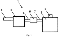
- the figure 1 is a schematic representation of the steam generating device according to the invention.
- the device 1 for generating steam comprises means for conveying a liquid in a tank 2 from a source of liquid, a tank 2 in which the liquid is heated. It further comprises an enclosure 3, separate from the tank 2, in which liquid vapor is generated, the tank 2 and the enclosure 3 being in fluid communication, and means for dispensing the steam produced.
- the liquid referred to in the present invention is all liquid suitable for, or accompanying, the heat treatment of one or a plurality of products to be heat treated.
- the liquid is preferably water, but it can also be water, or a mixture of oil and water, comprising one or more additives improving the cooking, or one or more pigments.
- the tank 2 has any suitable shape and is made of any materials, or assembly (s) of materials, adequate. It is intended, and able, to receive and store liquid before it is conveyed into the enclosure 3. It comprises, or is in communication with, all appropriate means for conveying the liquid into said tank 2 from the source of liquid. These means preferably comprise one or more openings made in the reservoir 2 and at least one pipe 4, in fluid communication with the liquid source.
- these means allow the controlled transfer of the liquid from the source of liquid to the tank 2, preferably according to various modifiable or adjustable parameters which are a function of the amount of steam to be produced. This has the advantage of bringing a determined quantity of liquid into the tank 2 for the generation of a defined quantity of liquid vapor.
- this controlled transfer of liquid is done automatically or driven by the user of the steam generating device 1 or the oven comprising generating device
- this automatic or controlled transfer is via programming means of the steam generating device 1, or the furnace comprising said device, comprising a user interface, such as for example a regulator or a touch screen.
- the transfer of liquid can be done at one time or in several times, spaced by programmable and variable lapses of time, for example a hundred milliliters for a few seconds.
- the sequential transfer of liquid in the tank 2 has the advantage of reducing thermal shocks.
- the liquid conveying means in the tank 2 comprise a pump or a valve.
- a valve more advantageously it is a solenoid valve, preferably controlled.
- the tank 2 mainly comprises, or mainly, liquid, without excluding the presence of a small proportion of liquid vapor.
- the tank 2, in particular in operation is at atmospheric pressure, or substantially at atmospheric pressure.
- This has the advantage of requiring less energy to heat, and keeping hot, the liquid in the tank 2, in comparison with a tank 2 which would be under liquid pressure, for example, and with respect to the generation of water vapor, in comparison with a water pressure vessel, which would be in fluid communication with a sanitary water supply, which is generally under a pressure of about 3 bar (300 kPa).
- the reservoir 2 is under liquid pressure, preferably at a controlled pressure, advantageously at a pressure lower than the pressure at which the liquid from the source of liquid is located.
- the tank 2 is at a regulated pressure, for example via a pressure reducer, at a pressure of about 2 bar less than the pressure of the pressure network. water.
- the tank 2 is sealed to allow pressurization and optionally comprises a safety valve.
- the liquid is conveyed from the source of liquid in the tank 2, at a lower temperature, greater than or equal to the ambient temperature at which the reservoir 2 is located, or at the temperature at which the liquid is heated, or maintained in the tank 2.
- the liquid conveying means in the reservoir 2 are preferably thermally insulated or are thermostated.
- the source of liquid, upstream of the tank 2 is preferably a water supply circuit, a water supply installation domestic hot water, or any suitable tanks.
- the liquid conveying means in the tank 2 further comprises one or more filters to remove any impurities in the liquid.
- the tank 2 further comprises a non-return valve, advantageously arranged between the tank 2 and the liquid source, which has the advantage of limiting heat losses towards the liquid source and limiting heating to liquid present in the tank 2.
- the reservoir 2 further comprises means for compensating for the expansion of the liquid, comprising for example a safety group or a deformable system under pressure comprising for example a membrane hydraulic reservoir.
- the tank 2 further comprises means for descaling the liquid.
- the liquid is in the tank 2 at a temperature greater than the temperature at which the reservoir 2, or the steam generating device 1, or the apparatus comprising said steam generating device 1, preferably greater than the ambient temperature, is advantageously at a temperature below the temperature boiling or vaporizing the liquid.
- the steam generating device 1 comprises means for heating the liquid present in the tank 2. These heating means can be arranged in the tank 2, or outside the tank 2.
- the preheating, in the tank 2, of the liquid to be vaporized, before its arrival in the vaporization chamber 3, has the advantage of allowing the heating temperatures of the liquid vaporization means to be reduced in the chamber 3. This allows a significant energy saving. Despite the fact that it is necessary to heat the liquid in the tank 2 in addition to the production of steam in the chamber 3, the reduction of the control temperature of the chamber 3 allows a significant energy gain. For the steam generating device 1, the energy saving achieved is about 37% compared with a conventional device, and about 6% for the furnace comprising the device 1 according to the invention in comparison with a classic oven.
- the water is heated in the tank 2 at a temperature of between about 40 and about 95 ° C.
- the liquid preheated in the tank 2 is supplied by controlled means for conveying the liquid from the tank 2 to the chamber 3.
- these conveying means are thermally insulated or are thermostated.
- they comprise one or more injection devices or assemblies, which comprises, or comprise, at least one device 5 for transferring the liquid from the reservoir 2 to the enclosure 3, at least one pipe 6 for delivering the liquid from the reservoir 2 and at least one pipe 7 for entering the liquid into the chamber 3.
- the device 5 for transferring the liquid from the reservoir 2 into the chamber 3 allows the controlled transfer of the liquid, according to various modifiable or adjustable parameters, preferably depending on the type of product or food to be cooked and / or the type of cooking and / or one or more cooking cycles. it has the advantage of bringing a determined amount of liquid into the chamber 3 for the generation of a defined amount of liquid vapor.
- this controlled transfer of the liquid is done by control means, automatically or user-driven steam generation device 1 or the furnace comprising steam generation device 1.
- this automatic transfer or piloted is done via programming means of the steam generating device 1 or the oven comprising said device comprising a user interface, such as a controller or a touch screen.
- these programming means interact with, include or are the programming means for the routing of the liquid from the source of liquid in the tank 2.
- the transfer of liquid from the tank 2 into the chamber 3 can be done in one go or in several times, spaced by programmable and variable lapses of time, for example a hundred milliliters for a few seconds.
- the sequential transfer of liquid has the advantage of reducing thermal shocks.
- the transfer device 5 is a pump or a valve.
- it is a valve, more advantageously it is a solenoid valve, preferably controlled.
- the chamber 3, in particular during operation, is under atmospheric pressure, or substantially at atmospheric pressure. This has the advantage of requiring less energy to generate liquid vapor, compared with an enclosure that would be under liquid pressure. In addition, the vapor pressure allows the latter to be transported to its place of use without the use of energy-consuming means, such as pumps.
- the enclosure 3 has any suitable shape and is made of any materials, or assembly (s) of materials, adequate. It is intended and capable of receiving the liquid to be vaporized and comprises, or is in communication with, all appropriate means for conveying the liquid in the enclosure 3, for example one or more openings and one or more pipes or conduits. In addition, it comprises, or is in communication with, steam distribution means generated, for its transport to its place of use, for example to the enclosure of baking an oven, said generated steam distribution means comprising one or more openings and one or more pipes or conduits 8.
- the enclosure 3 mainly comprises, or mainly, liquid vapor, without excluding the presence of liquid before vaporization or from the condensation of steam on the walls of the enclosure 3.
- the liquid vapor in the chamber 3 is generated, preferably almost instantaneously, by means of vaporization means of the liquid capable of vaporizing the liquid supplied or present in the chamber 3.
- the liquid vaporization means may be arranged in or outside the chamber 3.
- the liquid vapor in the chamber 3 is preferably generated from the liquid introduced into the chamber 3 at a temperature greater than the temperature at which the steam generating device 1 or the apparatus comprising said device is located.
- steam generation 1 preferably greater than room temperature, preferably at a temperature below the boiling or vaporization temperature of the liquid, which has the advantage of maximizing the energy gain of steam generation.
- the water is heated to a temperature of from about 180 to about 400 ° C.
- the means for dispensing the steam produced in the chamber 3 comprise at least one pipe 8 for conveying said steam to at least one apparatus to which the steam generating device 1 is coupled and / or integrated, for example towards the cavity cooking an oven.
- the use of the tank 2, distinct from the chamber 3, has the advantage, for a given volume of steam, of being able to reduce the dimensions and the weight of the steam generating chamber 3 with respect to the known devices. which allows it to have a small footprint, and thus, to be arranged artfully and easily near or in the frame, the oven for receiving it. Moreover, this reduced size also makes it possible to save by reducing the amount of energy required to heat a reduced volume and a reduced mass with respect to the enclosure 3.
- the use of the tank 2 and the controlled means of conveying the liquid from the tank 2 to the chamber 3 make it possible to control the quantity, and preferably also the moment of the steam generation, by controlling the quantity of liquid just needed to generate the amount of steam needed, depending on the stages of the cooking cycle and / or depending on the product to be cooked.
- the means for heating the liquid in the tank 2 and / or the means for vaporizing the liquid in the chamber 3 and / or the means for thermostating the routing of the liquid in the chamber 3 and / or possibly for conveying the liquid liquid in the tank 2, comprise and / or implement means for burning a gas or a liquid fuel, one or more electrical resistors, or solar radiation.
- these means are the heating means of the apparatus to which the steam generating device 1 is coupled or allow the use of the heat of the apparatus to which the steam generating device 1 is coupled.
- these means comprise and / or implement heat cogeneration means from the heat of the device (s) to which the device 1 for generating steam is coupled.
- these means comprise a heat exchanger.
- the steam generating device 1 is adapted to be coupled to, or is part of, one or more apparatuses, or assemblies, capable of using vapor of a liquid for the heat treatment of one or more products or objects.
- it is one or more cooking ovens, traditional ovens, professional or domestic, preferably for cooking food products, especially bread, or steaming ovens.
- the apparatus or appliances comprising the device 1 for generating steam according to the invention comprises any suitable means for heating the cooking cavity that the compound or compounds.
- it comprises, or they comprise, also means for stirring the internal atmosphere of the cooking cavity, for example a turbine or a fan, and, optionally, means for removing heat and / or the steam present in said cooking cavity with manual or automatic triggering.
- the apparatus or devices comprising the device 1 according to the invention comprises or furthermore comprises control means and / or control means and / or means for programming the treatment.
- thermal products to be treated for example cooking food.
- these means are coupled and / or interact and / or control the means for controlled delivery of the liquid from the tank 2 into the chamber 3 and / or the means for conveying the liquid from a source of liquid in the tank 2 preferably also the means for heating the liquid in the tank 2 and / or the means for vaporizing the liquid in the chamber 3 and / or the means for thermostating the delivery of the liquid in the chamber 3 and / or possibly for the routing of the liquid in the tank 2.
- the device or devices comprising the device 1 according to the invention can operate in different modes of operation, such as for example a so-called “economic” mode in which the energy saving is preferred, or in a mode called “Optimal” in which the optimum operation of the oven and the device 1 steam generator is preferred, or a so-called “balanced” mode in which the optimum operation of the oven and the device 1 steam generator is done while being energy efficient.
- the vapor generation method of a liquid according to the invention implements the device 1 for generating steam according to the invention.
- the method comprises a first step of conveying a liquid from a source of liquid in a tank 2, which is, in particular in operation, at atmospheric pressure, or substantially under atmospheric pressure, or under liquid pressure.
- this routing is controlled. It is based on the amount of liquid vapor to be generated.
- the quantity of liquid fed into the tank 2 is such as to allow the generation of the amount of steam required by the apparatus (s) to which the steam generator device 1 is couple.
- the quantity of liquid fed into the tank 2 is a function of the product to be heat treated, for example of the food to be cooked, and / or the heat treatment cycle or program and / or the phase of the cycle or treatment program. thermal.
- the method further comprises a preliminary step of filtering the liquid before it is conveyed into the tank 2.
- the liquid conveyed into the tank 2 is at a temperature higher than the temperature at which the tank 2 is located, preferably higher than the ambient temperature, or at the temperature at which the liquid is heated, or maintained.
- the delivery of the liquid into the tank 2 is preferably thermally insulated or thermostatically isolated.
- the method according to the invention further comprises a step of heating and / or maintaining the liquid in the tank 2 at a temperature higher than the ambient temperature at which the tank 2, or the steam generating device 1, or the apparatus comprising said steam generating device 1, and preferably at a temperature below the boiling or vaporization temperature of the liquid.
- the heated liquid is then transferred, preferably thermally or thermally insulated, from the tank 2 into the chamber 3, which in operation is at atmospheric pressure, or substantially at atmospheric pressure. Preferably, this transfer is controlled. It is based on the amount of liquid vapor to be generated.
- the quantity of liquid brought into the chamber 3 is such as to enable the generation of the amount of steam required by the apparatus (s) to which the steam generating device 1 is coupled.
- the quantity of liquid brought into the chamber 3 is a function of the product to be heat treated, for example of the food to be cooked, and / or the heat treatment cycle or program and / or the phase of the cycle or program of heat treatment.
- the liquid previously heated, is then heated to a temperature such that the liquid vaporizes, preferably instantaneously or almost instantly.
- the steam is then conveyed, preferably instantaneously or almost instantly after its generation, to at least one apparatus to which the steam generating device 1 is coupled and / or integrated.
- the heating of the liquid in the tank 2 and / or the vaporization of the liquid in the chamber 3 and / or the heating of the means for conveying the liquid into the chamber 3 and / or possibly for conveying the liquid into the tank 2 is or is produced by the combustion of a gas or a liquid fuel, by one or more electric resistors, or by solar radiation.
- this heating uses the heat produced and / or used by the device (s) to which the device 1 for generating steam is coupled.
- the method according to the invention is preferably implemented in a method of heat treatment of one or more products, preferably a method of cooking food products, in particular bread, using one or more traditional ovens, professional or domestic, or steaming ovens.
- the heat treatment method for example for cooking food products, comprises a step of controlling and / or controlling the heat treatment of the products to be treated.
- the method comprises a step of controlling and / or interaction of the routing of the liquid in the tank 2 and / or the routing of the liquid from the tank 2 in the chamber 3 and / or the heating of the liquid in the tank 2 and / or the vaporization of the liquid in the chamber 3 and / or the heating of the liquid during its transport in the chamber 3 and / or possibly during its transport in the tank 2, by and / or with the control and / or control of the heat treatment of the products to be heat treated, in particular to be cooked.
- the method comprises a step of determining the product to be cooked and / or the cooking cycle or program, this determination advantageously interacting with and / or controlling the heat treatment of the products to be treated and / or the delivery of the liquid to the product.
- this determination allows the evaluation of the amount of liquid vapor to be generated in the chamber 3 and the amount of liquid to be heated in the tank 2.
Landscapes
- Engineering & Computer Science (AREA)
- Life Sciences & Earth Sciences (AREA)
- General Engineering & Computer Science (AREA)
- Mechanical Engineering (AREA)
- Thermal Sciences (AREA)
- Physics & Mathematics (AREA)
- Sustainable Energy (AREA)
- Sustainable Development (AREA)
- Food Science & Technology (AREA)
- Chemical & Material Sciences (AREA)
- Combustion & Propulsion (AREA)
- Commercial Cooking Devices (AREA)
- Cookers (AREA)
Priority Applications (2)
| Application Number | Priority Date | Filing Date | Title |
|---|---|---|---|
| EP16290034.4A EP3207802A1 (de) | 2016-02-17 | 2016-02-17 | Dampferzeugungsvorrichtung ; ofen, der eine solche vorrichtung umfasst; verfahren zum dampferzeugen und garverfahren umfassend das genannte verfahren |
| EP16197001.7A EP3207801B1 (de) | 2016-02-17 | 2016-11-03 | Ofen umfassend eine dampferzeugungsvorrichtung und garverfahren, das einen solchen ofen verwendet |
Applications Claiming Priority (1)
| Application Number | Priority Date | Filing Date | Title |
|---|---|---|---|
| EP16290034.4A EP3207802A1 (de) | 2016-02-17 | 2016-02-17 | Dampferzeugungsvorrichtung ; ofen, der eine solche vorrichtung umfasst; verfahren zum dampferzeugen und garverfahren umfassend das genannte verfahren |
Publications (1)
| Publication Number | Publication Date |
|---|---|
| EP3207802A1 true EP3207802A1 (de) | 2017-08-23 |
Family
ID=55521644
Family Applications (2)
| Application Number | Title | Priority Date | Filing Date |
|---|---|---|---|
| EP16290034.4A Withdrawn EP3207802A1 (de) | 2016-02-17 | 2016-02-17 | Dampferzeugungsvorrichtung ; ofen, der eine solche vorrichtung umfasst; verfahren zum dampferzeugen und garverfahren umfassend das genannte verfahren |
| EP16197001.7A Not-in-force EP3207801B1 (de) | 2016-02-17 | 2016-11-03 | Ofen umfassend eine dampferzeugungsvorrichtung und garverfahren, das einen solchen ofen verwendet |
Family Applications After (1)
| Application Number | Title | Priority Date | Filing Date |
|---|---|---|---|
| EP16197001.7A Not-in-force EP3207801B1 (de) | 2016-02-17 | 2016-11-03 | Ofen umfassend eine dampferzeugungsvorrichtung und garverfahren, das einen solchen ofen verwendet |
Country Status (1)
| Country | Link |
|---|---|
| EP (2) | EP3207802A1 (de) |
Families Citing this family (4)
| Publication number | Priority date | Publication date | Assignee | Title |
|---|---|---|---|---|
| DE102018216931A1 (de) * | 2018-10-02 | 2020-04-02 | BSH Hausgeräte GmbH | Verfahren zum Betreiben eines Haushalts-Dampfbehandlungsgeräts sowie Haushalts-Dampfbehandlungsgerät |
| IT201900011499A1 (it) * | 2019-07-11 | 2021-01-11 | Moretti Forni S P A | Forno elettrico con vapore per alimenti |
| FR3105913B1 (fr) * | 2020-01-08 | 2023-11-17 | Eurofours Sa | Appareil à buée pour four de boulangerie-pâtisserie, et four de boulangerie-pâtisserie correspondant |
| CN111839198A (zh) * | 2020-08-03 | 2020-10-30 | 浙江亿田智能厨电股份有限公司 | 一种保鲜蒸饪多功能箱体 |
Citations (7)
| Publication number | Priority date | Publication date | Assignee | Title |
|---|---|---|---|---|
| US1086034A (en) | 1912-11-21 | 1914-02-03 | Howard Crouthamel | Baker's oven. |
| FR2410225A1 (fr) | 1977-11-29 | 1979-06-22 | Tipe Revent Ab | Four a convection |
| DE4403386C1 (de) * | 1994-02-04 | 1995-06-01 | Wiesheu Wiwa Gmbh | Vorrichtung zur Wärmebehandlung von Lebensmitteln |
| US20050072382A1 (en) * | 2003-08-29 | 2005-04-07 | Tippmann Vincent P. | Self cleaning boiler and steam generator |
| EP1617148A1 (de) | 2004-07-16 | 2006-01-18 | Samsung Electronics Co., Ltd. | Heizvorrichtung für Kochgerät |
| WO2009141995A1 (ja) * | 2008-05-23 | 2009-11-26 | 日清フーズ株式会社 | 冷凍食品解凍装置 |
| KR20130042977A (ko) * | 2011-10-19 | 2013-04-29 | 진금자 | 안전하고 급수탱크가 예열되는 스팀기 |
Family Cites Families (1)
| Publication number | Priority date | Publication date | Assignee | Title |
|---|---|---|---|---|
| ES2308952B1 (es) * | 2008-07-03 | 2009-11-16 | Electrodomesticos Taurus, S.L. | Plancha de vapor. |
-
2016
- 2016-02-17 EP EP16290034.4A patent/EP3207802A1/de not_active Withdrawn
- 2016-11-03 EP EP16197001.7A patent/EP3207801B1/de not_active Not-in-force
Patent Citations (7)
| Publication number | Priority date | Publication date | Assignee | Title |
|---|---|---|---|---|
| US1086034A (en) | 1912-11-21 | 1914-02-03 | Howard Crouthamel | Baker's oven. |
| FR2410225A1 (fr) | 1977-11-29 | 1979-06-22 | Tipe Revent Ab | Four a convection |
| DE4403386C1 (de) * | 1994-02-04 | 1995-06-01 | Wiesheu Wiwa Gmbh | Vorrichtung zur Wärmebehandlung von Lebensmitteln |
| US20050072382A1 (en) * | 2003-08-29 | 2005-04-07 | Tippmann Vincent P. | Self cleaning boiler and steam generator |
| EP1617148A1 (de) | 2004-07-16 | 2006-01-18 | Samsung Electronics Co., Ltd. | Heizvorrichtung für Kochgerät |
| WO2009141995A1 (ja) * | 2008-05-23 | 2009-11-26 | 日清フーズ株式会社 | 冷凍食品解凍装置 |
| KR20130042977A (ko) * | 2011-10-19 | 2013-04-29 | 진금자 | 안전하고 급수탱크가 예열되는 스팀기 |
Also Published As
| Publication number | Publication date |
|---|---|
| EP3207801B1 (de) | 2019-10-02 |
| EP3207801A1 (de) | 2017-08-23 |
Similar Documents
| Publication | Publication Date | Title |
|---|---|---|
| EP3207801B1 (de) | Ofen umfassend eine dampferzeugungsvorrichtung und garverfahren, das einen solchen ofen verwendet | |
| EP0181248B1 (de) | Verfahren zum Erhitzen einer Flüssigkeit mittels Tauchverbrennung und Anlage zum Durchführen dieses Verfahrens | |
| US5209218A (en) | Deep frying apparatus | |
| US7677162B2 (en) | High temperature, oil saving, rapid cook fryer system | |
| FR2520199A1 (fr) | Appareil et procede pour faire lever la pate | |
| CN101925319A (zh) | 用于制备饮料的混合式设备 | |
| WO2000032524A1 (fr) | Procede et dispositif d'incineration et de vitrification de dechets, notamment radioactifs | |
| EP2572583B1 (de) | Facility and method for treating food products, such as cellular products, in particular for expanding said products | |
| EP2453752B1 (de) | Nahrungsmittelsbackofen und verfahren zum kochen einem getreide basierten teig | |
| WO1988007163A1 (fr) | Four pour deshydrater pulverulents, sable ou granulats | |
| JP2002272604A (ja) | 過熱蒸気による加熱方法及び加熱装置 | |
| CA2789173C (fr) | Yaourtiere menagere et procede de fabrication rapide de yaourt | |
| EP2883482A1 (de) | Einfache und preisgünstige Dampfkochvorrichtung, die zwei Kochtemperaturen erlaubt | |
| EP2960593B1 (de) | Heizsystem eines gasflusses, und anlage, die dieses system anwendet | |
| CN113940553B (zh) | 蒸汽饭煲的低温烹饪方法 | |
| EP1151705B1 (de) | Verfahren zur Temperaturregelung in einem Dampfofen | |
| WO2022068090A1 (zh) | 一种电热汽化机构及高温蒸汽发生装置 | |
| CN201203095Y (zh) | 一种高温微压蒸汽发生装置 | |
| EP1162279B1 (de) | Aufkohlungsanlage mit Gasaufheizung | |
| FR3003770A1 (fr) | Dispositif d'hydratation d'un materiau thermochimique pour la production d'energie thermique | |
| EP1772669A2 (de) | Einrichtung zum Heizen und Erzeugen von Dampf für Garofen | |
| FR3105913A1 (fr) | Appareil à buée pour four de boulangerie-pâtisserie, et four de boulangerie-pâtisserie correspondant | |
| BE1006931A6 (fr) | Un procede de preparation de pate. | |
| EP0121643B1 (de) | Mit Wasserdampf, Elektrizität oder innerer Verbrennung beheizte mobile Öfen in Modulbauweise | |
| EP0042793B1 (de) | Vorrichtung zum Löschen hydraulischer Flugasche und ähnlicher Produkte |
Legal Events
| Date | Code | Title | Description |
|---|---|---|---|
| PUAI | Public reference made under article 153(3) epc to a published international application that has entered the european phase |
Free format text: ORIGINAL CODE: 0009012 |
|
| AK | Designated contracting states |
Kind code of ref document: A1 Designated state(s): AL AT BE BG CH CY CZ DE DK EE ES FI FR GB GR HR HU IE IS IT LI LT LU LV MC MK MT NL NO PL PT RO RS SE SI SK SM TR |
|
| AX | Request for extension of the european patent |
Extension state: BA ME |
|
| STAA | Information on the status of an ep patent application or granted ep patent |
Free format text: STATUS: THE APPLICATION IS DEEMED TO BE WITHDRAWN |
|
| 18D | Application deemed to be withdrawn |
Effective date: 20180224 |