EP3207827A1 - Reisebett - Google Patents
Reisebett Download PDFInfo
- Publication number
- EP3207827A1 EP3207827A1 EP15850194.0A EP15850194A EP3207827A1 EP 3207827 A1 EP3207827 A1 EP 3207827A1 EP 15850194 A EP15850194 A EP 15850194A EP 3207827 A1 EP3207827 A1 EP 3207827A1
- Authority
- EP
- European Patent Office
- Prior art keywords
- rod
- locking
- connector
- block
- connecting rod
- Prior art date
- Legal status (The legal status is an assumption and is not a legal conclusion. Google has not performed a legal analysis and makes no representation as to the accuracy of the status listed.)
- Granted
Links
Images


Classifications
-
- A—HUMAN NECESSITIES
- A47—FURNITURE; DOMESTIC ARTICLES OR APPLIANCES; COFFEE MILLS; SPICE MILLS; SUCTION CLEANERS IN GENERAL
- A47D—FURNITURE SPECIALLY ADAPTED FOR CHILDREN
- A47D13/00—Other nursery furniture
- A47D13/06—Children's play- pens
- A47D13/061—Children's play- pens foldable
- A47D13/063—Children's play- pens foldable with soft walls
-
- A—HUMAN NECESSITIES
- A47—FURNITURE; DOMESTIC ARTICLES OR APPLIANCES; COFFEE MILLS; SPICE MILLS; SUCTION CLEANERS IN GENERAL
- A47D—FURNITURE SPECIALLY ADAPTED FOR CHILDREN
- A47D7/00—Children's beds
- A47D7/002—Children's beds foldable
-
- B—PERFORMING OPERATIONS; TRANSPORTING
- B68—SADDLERY; UPHOLSTERY
- B68G—METHODS, EQUIPMENT, OR MACHINES FOR USE IN UPHOLSTERING; UPHOLSTERY NOT OTHERWISE PROVIDED FOR
- B68G5/00—Resilient upholstery pads
-
- A—HUMAN NECESSITIES
- A47—FURNITURE; DOMESTIC ARTICLES OR APPLIANCES; COFFEE MILLS; SPICE MILLS; SUCTION CLEANERS IN GENERAL
- A47D—FURNITURE SPECIALLY ADAPTED FOR CHILDREN
- A47D13/00—Other nursery furniture
-
- A—HUMAN NECESSITIES
- A47—FURNITURE; DOMESTIC ARTICLES OR APPLIANCES; COFFEE MILLS; SPICE MILLS; SUCTION CLEANERS IN GENERAL
- A47D—FURNITURE SPECIALLY ADAPTED FOR CHILDREN
- A47D13/00—Other nursery furniture
- A47D13/06—Children's play- pens
-
- A—HUMAN NECESSITIES
- A47—FURNITURE; DOMESTIC ARTICLES OR APPLIANCES; COFFEE MILLS; SPICE MILLS; SUCTION CLEANERS IN GENERAL
- A47D—FURNITURE SPECIALLY ADAPTED FOR CHILDREN
- A47D13/00—Other nursery furniture
- A47D13/06—Children's play- pens
- A47D13/068—Children's play- pens extensible
-
- A—HUMAN NECESSITIES
- A47—FURNITURE; DOMESTIC ARTICLES OR APPLIANCES; COFFEE MILLS; SPICE MILLS; SUCTION CLEANERS IN GENERAL
- A47D—FURNITURE SPECIALLY ADAPTED FOR CHILDREN
- A47D7/00—Children's beds
Definitions
- the present disclosure relates to the field of children's products, in particular, to a travel bed.
- a foldable travel bed comprises a foldable bedstead mainly comprising a bottom support, a surrounding frame and stand rods supporting between the bottom support and the surrounding frame.
- the whole bedstead is folded by folding the bottom support and the surrounding frame, and the foldable bottom support and surrounding frame have locking mechanisms respectively to lock at a unfolded position, the locking mechanism of the bottom support is located at a central position thereof, the locking mechanism of the surrounding frame is located on the surrounding rod of the surrounding frame.
- the locking mechanism of the surrounding frame is driven to be unlocked by unlocking the locking mechanism at the center of the bottom support, such that the bottom support and the surrounding frame are folded, and then the folding of the whole bedstead is achieved.
- the unfolding is in the same way.
- a structure to be unlocked or locked respectively causes a complicated structure of the travel bed in one aspect, and is very inconvenient for users to operate in another aspect.
- the present disclosure is intended to provide a travel bed.
- a travel bed has a unfolded state and a folded state, and comprises a bottom support, a upper surrounding frame, a plurality of stand rods provided between the bottom support and the upper surrounding frame, and fixing bases provided at lower portions of the plurality of stand rods respectively, the bottom support comprising a plurality of bottom rods and a connecting base rotatably connected with ends of the plurality of bottom rods, the other ends of the bottom rods being connected with the fixing bases;
- the upper surrounding frame comprises a first surrounding rod and a second surrounding rod which are rotatably connected with a first connector respectively, and an upper end of the upright rod is fixedly connected with the first connector;
- the first surrounding rod comprises a first connecting rod and a second connecting rod of which end portions are rotatably connected via a second connector, and the second surrounding rod comprises a third connecting rod and a fourth connecting rod of which end portions are rotatably connected via a third connector;
- the upper surrounding frame further comprises a first locking device for locking the first connecting rod and the second connecting rod to each other, and a second locking device for locking the third connecting rod and the fourth connecting rod to each other;
- the first locking device is provided on the second connector, the second locking device is provided on the third connector, and the first locking device and the second locking device are linked with each other via a hauling rope; during folding, when one of the first locking device and the second locking device is unlocked, the other locking device is unlocked simultaneously, the connecting base is driven to move upwardly by pressing the upper surrounding frame downwardly
- the first locking device comprises a first locking unit for locking the first connecting rod and the second connecting rod to the second connector respectively, and a first unlocking unit for unlocking the first locking unit
- the second locking device comprises a second locking unit for locking the third connecting rod and the fourth connecting rod to the third connector respectively, and a second unlocking unit for unlocking the second locking unit
- two end portions of the hauling rope are connected to the first unlocking unit and the second unlocking unit respectively, and the first locking unit and the second locking unit are unlocked simultaneously when the first unlocking unit is conducted an unlocking operation.
- the first locking unit comprises a first swaying block of which an end portion is rotatably connected with the second connector, and a first locking block fixed on an end portion of the first connecting rod and an end portion of the second connecting rod respectively and rotatably connected with the second connector, the first swaying block and the first locking block are pressed against each other when the first locking unit is in a locked state, and the first swaying block and the first locking block are separated from each other when the first locking unit is in an unlocked state.
- the second locking unit comprises a second locking block fixed on an end portion of the third connecting rod and an end portion of the fourth connecting rod respectively and rotatably connected with the third connector, a second swaying block of which an end portion is rotatably connected with the second locking block, and a connecting block rotatably connected with the other end portion of the second swaying block and with the third connector respectively, the third connector, the second locking block, the second swaying block and the connecting block form a four-bar linkage mechanism, and the second locking unit is in a locked state when the four-bar linkage mechanism is at a dead point position.
- the first unlocking unit comprises an unlocking handle knob slidably provided on the second connector along an up-down direction, a first sliding slot provided on the unlocking handle knob and extending along the up-down direction, a second sliding slot provided on the second connector and extending along a horizontal direction, and a first pin provided on the other end portion of the first swaying block
- the first sliding slot comprises a tilted slot extending along the up-down direction
- the first pin is able to slidably pass through the first sliding slot and the second sliding slot along the first sliding slot and the second sliding slot.
- the first sliding slot further comprises a straight slot extending along the up-down direction, and the straight slot is connected with the tilted slot, and the straight slot is located in the first sliding slot at an initial end of a sliding direction of the first pin during the unlocking of the unlocking handle knob.
- the second connector is provided with an unlocking handle knob able to slide along an up-down direction and a first driving part able to rotate
- the second unlocking unit comprises a second driving part slidably provided on the third connector along the up-down direction
- the first driving part is fixedly connected with an end portion of the hauling rope
- the second driving part is fixedly connected with the other end portion of the hauling rope
- the unlocking handle knob slides to drive the first driving part to rotate and the first driving part drives the hauling rope to pull the second driving part to slide and cause the second locking unit to unlock.
- a second pin is provided on the unlocking handle knob and fitted with the first driving part, and the unlocking handle knob slides and drives the first driving part to rotate via the second pin.
- the second swaying block is fitted with the second driving part and rotatably connected with the connecting block via a third pin
- the third connector is provided with a third sliding slot
- the third pin is able to slidably pass through the third sliding slot along the third sliding slot, and when the second driving part slides, it drives the second swaying block to sway and the third pin to slide in the third sliding slot until the four-bar linkage mechanism passing the dead point, and the second locking unit is unlocked.
- the travel bed further comprises a top rod provided within the stand rod and able to slide along a length direction of the stand rod, top rod braces for connecting the top rod to the first surrounding rod and the second surrounding rod respectively, and an elastic part sleeved outside the top rod, the top rod is rotatably connected with lower end portions of the top rod braces, upper end portions of the top rod braces are rotatably connected with the first surrounding rod and the second surrounding rod, an upper end portion of the elastic part presses against the lower end portions of the top rod braces, and during unfolding the travel bed, the elastic part pushes against the lower end portions of the top rod braces upwardly, and drives the upper surrounding frame to unfold upwardly.
- an upper connecting block is fixed on an upper portion of the top rod, the lower end portion of the top rod brace is rotatably connected with the upper connecting block, and the upper end portion of the elastic part presses against the upper connecting block;
- a top rod fixing sleeve is fixedly provided on the stand rod, a lower portion of the top rod is inserted in the top rod fixing sleeve, and a lower end portion of the elastic part presses against an upper end portion of the top rod fixing sleeve.
- the travel bed further comprises a top rod extending along a height direction of the travel bed, and top rod braces for connecting the top rod to the first surrounding rod and the second surrounding rod respectively, an upper end portion of the top rod is rotatably connected with lower end portions of the top rod braces, and upper end portions of the top rod braces are rotatably connected with the first surrounding rod and the second surrounding rod.
- the travel bed further comprises a cam assembly provided on respective fixing base, the cam assembly comprises a top rod bulge fixedly connected with the bottom of the top rod, and a bottom rod recess fixedly connected to the other end portion of the bottom rod and rotatably connected with the fixing base, and the top rod bulge is accommodated in the bottom rod recess.
- the third connector in at least one other direction may be unlocked simultaneously by unlocking the second connector on the surrounding rods so as to achieve the folding of the surrounding frames, then the bottom rods and the bottom support are driven to be folded synchronously by the top rod mechanism on the stand rod, and the bedstead is folded quickly, easily and conveniently.
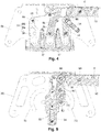
- a travel bed as shown in Figure 1 has a unfolded state and a folded state, and comprises a bottom support, a upper surrounding frame, four stand rods 1 provided between the bottom support and the upper surrounding frame, and fixing bases 20 provided at lower portions of the four stand rods 1 respectively.
- Each component is introduced in detail in the following:
- a wheel 21 is provided on the fixing base 20.
- the upper surrounding frame comprises: a first surrounding rod and a second surrounding rod of which end portions are rotatably connected with a first connector 32 via shafts d1 and d2 as well as shafts d3 and d4 respectively;
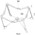
- the first surrounding rod comprises a first connecting rod 30 and a second connecting rod 31 of which end portions are rotatably connected with a second connector 330 via shafts e1 and e2 as well as shafts e3 and e4 respectively
- the first connecting rod 30 comprises a first upper rod 300 and a first lower rod 301 which are arranged in parallel
- the second connecting rod 31 comprises a second upper rod 310 and a second lower rod 311 which are arranged in parallel
- the second surrounding rod comprises a third connecting rod 35 and a fourth connecting rod 36 of which end portions are rotatably connected with a third connector 340 via shafts e5 and e6 as well as shafts e7 and e8 respectively
- the third connecting rod 35 comprises a third upper rod 350 and a third lower rod
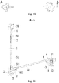
- the travel bed comprises a top rod 50 extending along a length direction of the stand rod 1, top rod braces 6 for connecting the top rod 50 to the first surrounding rod and the second surrounding rod respectively, wherein, an upper end portion of the stand rod 1 is fixedly connected to the first connector 32, a top rod fixing sleeve 51 is provided on the stand rod 1, and the top rod 50 is arranged in the top rod fixing sleeve 51.
- top rod 50 An upper end portion of the top rod 50 is connected with two top rod braces 6 respectively, and the two top rod braces 6 are rotatably connected with the first surrounding rod and the second surrounding rod which are connected to the same first connector 32, specifically, the first lower rod 301 and the third lower rod 351 as well as the second lower rod 311 and the fourth lower rod 361, via shafts g1 and g2 as well as shafts g3 and g4, respectively.
- the travel bed further comprises a cam assembly provided on respective fixing base 20, the cam assembly comprises a top rod bulge 501 fixedly connected with the bottom of the top rod 50 and a bottom rod recess 401 fixedly connected to the other end portion of the bottom rod 40 and rotatably connected with the fixing base 20 via a shaft f, and the top rod bulge 501 is accommodated in the bottom rod recess 401.
- the first lower rod 301, the second lower rod 311, the third lower rod 351 and the fourth lower rod 361 rotate to press the top rod 50 downwardly and cause the top rod bulge 501 to press the bottom rod recess 401 downwardly such that the end of the bottom rod 40 connected with the connecting base rotates upwardly by taking the bottom rod recess 401 as a shaft, and in this way it is achieved that the stand rods 1 get close to the center and fold up in an approximate upright and parallel to each other manner.
- the upper surrounding frame further comprises a first locking unit for locking the first upper rod 300 of the first connecting rod 30and the second upper rod 310 of the second connecting rod 31 to the second connector 330 respectively, a first unlocking unit for unlocking the first locking unit, a second locking unit for locking the third upper rod 350 of the third connecting rod 35 and the fourth upper rod 360 of the fourth connecting rod 36 to the third connector 340 respectively, and a second unlocking unit for unlocking the second locking unit, the first unlocking unit and the second unlocking unit are linked to each other via a hauling rope 37, and the first locking unit and the second locking unit are unlocked simultaneously when one of the first unlocking unit and the second unlocking unit is conducted an unlocking operation.
- the first locking unit comprises a first swaying block 331 of which an end portion is rotatably connected with the second connector 330, and a first locking block 332 fixed on an end portion of the first connecting rod 30 and an end portion of the second connecting rod 31 respectively and rotatably connected with the second connector 330, and in the present embodiment, the rotating shafts of the first locking block 332 and the second connector 330 are the above mentioned shafts e1 and e2, respectively.
- the first swaying block 331 and the first locking block 332 are pressed against each other to cause that the first locking block 332 is not able to rotate downwardly, that is, the first connecting rod 30 and the second connecting rod 31 cannot rotate with respect to the second connector 330, and when the first locking unit is in an unlocked state, the first swaying block 331 and the first locking block 332 are separated from each other, the first connecting rod 30 and the second connecting rod 31 rotates around the rotatable connecting shaft between the respective connecting rod and the second connector 330, and the first connecting rod 30 and the second connecting rod 31 can be folded.
- the first unlocking unit comprises an unlocking handle knob 338 slidably provided on the second connector 330 along an up-down direction, a first sliding slot 335 provided on each of two opposite sides of the unlocking handle knob 338 and extending along the up-down direction, a second sliding slot 333 provided on each of two opposite sides of the second connector 330 and extending along a horizontal direction, and a first pin 800 provided on the other end portion of the first swaying block 331, the first sliding slot 335 comprises a tilted slot 335a extending along the up-down direction, and the first pin 800 is able to slidably pass through the first sliding slot 335 and the second sliding slot 333 along the first sliding slot 335 and the second sliding slot 333.
- the unlocking handle knob 338 When the unlocking handle knob 338 slides, it drives the first pin 800 to slide in the first sliding slot 335 and the second sliding slot 333, and drives the first swaying block 331 to rotate to press against or be separated from the first locking block 332.
- the first pin 800 when the first locking unit is locked, the first pin 800 is located at an outer end of the second sliding slot 333 and an upper end of the first sliding slot 335; when the first locking unit is unlocked, the first pin 800 is located at an inner end of the second sliding slot 333 and a lower end of the first sliding slot 335, and by pushing the unlocking handle knob 338 upwardly, the first swaying block 331 is caused to rotate and separate from the first locking block 332, and the first locking unit is in the unlocked state.
- the first locking unit further comprises a first elastic part 334 for driving the first swaying block 331 to return from the unlocked state to the locked state, and in the present embodiment, the first elastic part 334 employs a spring, of which two ends are connected with the second connector 330 and the first pin 800 respectively.
- the second locking unit comprises a second locking block 342 fixed on an end portion of the fourth connecting rod 36 and an end portion of the third connecting rod 35 respectively and rotatably connected with the third connector 340, a second swaying block 341 of which an end portion is rotatably connected with the second locking block 342, and a connecting block 344 rotatably connected with the other end portion of the second swaying block 341 and with the third connector 340 respectively, the third connector 340, the second locking block 342, the second swaying block 341 and the connecting block 344 form a four-bar linkage mechanism, and the second locking unit is in the locked state when the four-bar linkage mechanism is at a dead point position.
- there are two four-bar linkage mechanisms which are provided on the third connector 340 symmetrically.
- the second swaying block 341 and the connecting block 344 are rotatably connected via a third pin 802
- the connecting block 344 and the second connector 340 are rotatably connected via a fourth pin 803
- the second connector 340 and the second locking block 342 are rotatably connected via a fifth pin 804 (in the present embodiment, the fifth pins 804 are shafts e5 and e7)
- the second locking block 342 and the second swaying block 341 are rotatably connected via a sixth pin 805, the lineation of the centers of the fourth pin 803 and the sixth pin 805 forms a straight line, and when the center of the third pin 802 is located on this straight line, or when the centers of the third pin 802 and the fifth pin 804 are located at two sides of this straight line respectively, the four-bar linkage mechanism is at the dead point position, and when the center of the third pin 802 moves toward the side where the center of the fifth pin 804 is located and passes through the above mentioned straight line, the four
- the unlocking handle knob 338 is provided with the second connector 330 able to slide in the up-down direction and a rotatable first driving part 336.
- the second unlocking unit comprises a second driving part 346 slidably provided on the third connector 340 along the up-down direction, the first driving part 336 is fixedly connected with an end portion of the hauling rope 37, the second driving part 346 is fixedly connected with the other end portion of the hauling rope 37, and the hauling rope 37 is arranged in the tube cavities of the fourth connecting rod 36, the third connecting rod 35, the first connecting rod 30 and the second connecting rod 31 to result in a clean and tidy appearance of the surrounding frame.
- the above mentioned two four-bar linkage mechanisms are provided at the two opposite sides of the second driving part 346 symmetrically.
- a second pin 801 is provided with the unlocking handle knob 338, the second pin 801 is fitted with the first driving part 336, the second swaying block 341 is fitted with the second driving part 346, third sliding slots 343 are provided at two opposite sides of the third connector 340, the third sliding slots 343 are arc-shaped slots and extend along the up-down direction.
- the third pin 802 passes through the third slot 343 and can slide along the third slot 343, and in the present embodiment, when the second locking unit is in the locked state, the third pin 802 is at the upper end of the third slot 343, and when the second locking unit is in the unlocked state, the third pin 802 is at the lower end of the third slot 343.
- the first driving part 336 is driven to rotate via the cooperation between the second pin 801 and the first driving part 336, rotating of the first driving part 336 tenses the hauling rope 37 tightly, the hauling rope 37 pulls the second driving part 346 to slide upwardly, and the second swaying block 341 is driven to sway by the cooperation between the second driving part 346 and the second swaying block 341, such that the third pin 802 slides in the third sliding slot 343 toward the fifth pin 804 from top to bottom, until the center of the third pin 802 slides to pass over the straight line on which the centers of the fourth pin 803 and the sixth pin 805 are located, that is, a four-bar linkage mechanism formed by the third connector 340, the second locking block 342, the second swaying block 341, and the connecting block 344 passes the dead point, then the second locking unit is unlocked, and the fourth connecting rod 36 and the third connecting rod 35 may rotate
- the first sliding slot 335 further comprises a straight slot 335b extending along the up-down direction, and the straight slot 335b is connected with the tilted slot 335a, and located in the first sliding slot 335 at an initial end of a sliding direction of the first pin 800 during the unlocking of the unlocking handle knob 338.
- the straight slot 335b is located at the upper end of the tilted slot 335a.
- the surrounding frame further comprises a second elastic part 337 and a third elastic part 345 for driving the unlocking handle knob 338 and the second driving part 346 to return from the unlocked state to the locked state respectively, and the second elastic part 337 and the third elastic part 338 employ springs, two ends of the second elastic part 337 are connected with the unlocking handle knob 338 and the second connector 330 respectively, and two ends of the third elastic part 345 are connected with the second driving part 346 and the third connector 340 respectively.
- the first connecting rod 30, the second connecting rod 31, the third connecting rod 35 and the fourth connecting rod 36 are all in the unfolded state with respect to each other, and the first locking unit and the second locking unit are both locked.
- the travel bed When the travel bed is required to be unfolded: pressing the connecting base downwardly to unfold the bottom rod 40, and meanwhile, the surrounding frame being driven to get unfolded, and then it is achieved by locking the first locking unit and the second locking unit.
- the bedstead is unfolded by lifting the second connector 330 or the third connector 340, and then it is achieved by locking the first locking unit and the second locking unit, and during the unfolding process, there is no need to operate the unlocking handle knob 338.
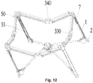
- the present embodiment differs from Embodiment 1 only by that: the top rod 50 is able to slide along the length direction of the stand rod 1, and the travel bed further comprises a spring 7 sleeved outside the top rod 50, wherein, the lower portion of the top rod 50 is inserted into the top rod fixing sleeve 51, the upper portion of the top rod 50 is fixedly provided with an angular upper connecting block 52, the top rod brace 6 is rotatably connected to the upper connecting block 52, an upper end portion of the spring 7 presses against the upper connecting block 52 and a lower end portion of the spring 7 presses against the upper end portion of the top rod fixing sleeve 51.
- the first connecting rod 30 (the first upper rod 300 and the first lower rod 301) and the second connecting rod 31 (the second upper rod 310 and the second lower rod 311) rotate and get close to each other
- the third connecting rod 35 (the third upper rod 350 and the third lower rod 351) and the fourth connecting rod 36 (the fourth upper rod 360 and the fourth lower rod 361) rotate and get close to each other
- the top rod 50 is pressed downwardly and meanwhile, the top rod brace 6 compresses the spring 7 downwardly
- the top rod bulge 501 presses the bottom rod recess 401 downwardly
- the end of the bottom rod 40 connected with the connecting base rotates upwardly by taking the bottom rod recess 401 as a shaft, and in this way it is achieved that the stand rods 1 get close to the center and fold up in an approximate upright and parallel to each other manner, and the spring 7 is in a compressed state, as shown in
- the spring 7 in the compressed state releases its elastic force and presses the top rod brace 6 upwardly via the upper portion thereof, the top rod brace 6 rotates and pushes the first lower rod 301, the second lower rod 311, the third lower rod 351 and the fourth lower rod 361 to rotate, and the upper surrounding frame is automatically opened under the action of the elastic force.
Landscapes
- Engineering & Computer Science (AREA)
- Mechanical Engineering (AREA)
- Invalid Beds And Related Equipment (AREA)
Applications Claiming Priority (4)
| Application Number | Priority Date | Filing Date | Title |
|---|---|---|---|
| CN201410553161.3A CN104323625B (zh) | 2014-10-17 | 2014-10-17 | 旅行床 |
| CN201510190411.6A CN104799610A (zh) | 2015-04-21 | 2015-04-21 | 旅行床 |
| CN201520364150.0U CN204764476U (zh) | 2015-06-01 | 2015-06-01 | 围框杆、围框及旅行床 |
| PCT/CN2015/091745 WO2016058505A1 (zh) | 2014-10-17 | 2015-10-12 | 旅行床 |
Publications (3)
| Publication Number | Publication Date |
|---|---|
| EP3207827A1 true EP3207827A1 (de) | 2017-08-23 |
| EP3207827A4 EP3207827A4 (de) | 2018-09-12 |
| EP3207827B1 EP3207827B1 (de) | 2020-07-15 |
Family
ID=55746131
Family Applications (1)
| Application Number | Title | Priority Date | Filing Date |
|---|---|---|---|
| EP15850194.0A Active EP3207827B1 (de) | 2014-10-17 | 2015-10-12 | Reisebett |
Country Status (3)
| Country | Link |
|---|---|
| US (1) | US10980356B2 (de) |
| EP (1) | EP3207827B1 (de) |
| WO (1) | WO2016058505A1 (de) |
Cited By (2)
| Publication number | Priority date | Publication date | Assignee | Title |
|---|---|---|---|---|
| GB2570371A (en) * | 2017-11-15 | 2019-07-24 | Wonderland Switzerland Ag | Foldable play yard |
| EP4635374A3 (de) * | 2021-06-23 | 2025-11-26 | Wonderland Switzerland AG | Babybett |
Families Citing this family (30)
| Publication number | Priority date | Publication date | Assignee | Title |
|---|---|---|---|---|
| US10080444B2 (en) * | 2012-09-14 | 2018-09-25 | Cappybug, Llc | Folding playpen and dual sleeper |
| US10709260B2 (en) * | 2015-06-13 | 2020-07-14 | Shanghai Daafu Baby Carrier Co., Ltd | Connecting rod folding mechanism and cot having same |
| IT201700053972A1 (it) * | 2017-05-18 | 2018-11-18 | Artsana Spa | Culla per bambini |
| CN108477911B (zh) * | 2018-04-28 | 2024-02-27 | 好孩子儿童用品有限公司 | 旅行床 |
| CN109171319B (zh) * | 2018-11-08 | 2024-06-07 | 安徽酷豆丁科技发展股份有限公司 | 一种一键收合式床架以及游戏床 |
| US11363893B2 (en) * | 2018-11-08 | 2022-06-21 | Henry F. Thorne | Foldable play yard |
| US11723478B2 (en) * | 2019-03-05 | 2023-08-15 | Thorley Industries, Llc | Foldable child enclosure |
| US12575688B2 (en) | 2019-06-17 | 2026-03-17 | Henry F. Thorne | Play yard |
| CN110338595B (zh) * | 2019-07-04 | 2024-06-18 | 安徽酷豆丁科技发展股份有限公司 | 一种快捷收合的婴儿床架 |
| JP7413504B2 (ja) * | 2019-08-07 | 2024-01-15 | ワンダーランド スイツァーランド アーゲー | 折り畳み式遊具 |
| US11559146B2 (en) | 2019-08-07 | 2023-01-24 | Wonderland Switzerland Ag | Foldable playard having X-frame assemblies and canopy cover |
| US11700953B2 (en) * | 2019-09-18 | 2023-07-18 | Wonderland Switzerland Ag | Child care apparatus |
| CA3160783A1 (en) | 2019-12-04 | 2021-06-10 | Jonathan M. Pacella | Foldable playard having x-frame assemblies and canopy cover |
| WO2021110537A1 (en) | 2019-12-04 | 2021-06-10 | Wonderland Switzerland Ag | Canopy bow assembly secured by a snap clip |
| AU2021207544B2 (en) | 2020-01-17 | 2024-09-26 | Wonderland Switzerland Ag | Bassinet accessory for a playard |
| CN112043115B (zh) * | 2020-09-30 | 2025-02-18 | 昆山爱思贝儿童用品有限公司 | 折叠关节及婴幼儿床 |
| CN112695501B (zh) * | 2020-12-24 | 2025-04-04 | 广东工业大学 | 一种可伸缩避雨衣架 |
| CN114762558A (zh) * | 2021-01-14 | 2022-07-19 | 明门瑞士股份有限公司 | 婴儿床架 |
| US11518653B2 (en) * | 2021-04-09 | 2022-12-06 | Juan-Carlos G. De Ledebur | Foldable elevator structure |
| CN114431672A (zh) * | 2022-03-04 | 2022-05-06 | 六安宝乐儿童用品有限责任公司 | 一种可折叠的床扶手结构 |
| CN219088811U (zh) * | 2023-01-18 | 2023-05-30 | 安徽酷豆丁科技发展股份有限公司 | 一种折叠床结构 |
| CN116763101B (zh) * | 2023-06-25 | 2025-11-28 | 四川欣茂塑业有限公司 | 翻折机构及婴儿床架和可折叠婴儿床 |
| USD1120685S1 (en) * | 2023-09-04 | 2026-03-31 | Wonderland Switzerland Ag | Crib |
| CN117356874A (zh) * | 2023-10-25 | 2024-01-09 | 宁波妈咪宝婴童用品制造有限公司 | 一种用于儿童床的上围框及骨架 |
| USD1111527S1 (en) * | 2024-01-16 | 2026-02-10 | China Wonderland Nurserygoods Co., Ltd. | Crib |
| WO2025162323A1 (zh) * | 2024-01-30 | 2025-08-07 | 明门瑞士股份有限公司 | 可收合婴儿床 |
| USD1098890S1 (en) * | 2024-02-02 | 2025-10-21 | Xiamen Honor Industry and Trading Co., Ltd. | Crib frame |
| WO2025188312A1 (en) * | 2024-03-08 | 2025-09-12 | Thorne Henry F | Play yard |
| CN119366764A (zh) * | 2024-07-31 | 2025-01-28 | 好孩子儿童用品有限公司 | 儿童床 |
| US12557921B1 (en) * | 2025-04-01 | 2026-02-24 | Xiamen Honor Industry and Trading Co., Ltd. | Folding frame |
Family Cites Families (50)
| Publication number | Priority date | Publication date | Assignee | Title |
|---|---|---|---|---|
| US3119124A (en) * | 1962-05-31 | 1964-01-28 | Robert D Krauss | Play pen |
| CN2116399U (zh) | 1992-01-23 | 1992-09-23 | 吴正建 | 便携式野战床 |
| US5353451A (en) * | 1993-06-03 | 1994-10-11 | Hsiung Yu Kuang | Playpen frame structure |
| US5483710A (en) * | 1994-01-11 | 1996-01-16 | Chan; Te-Erh | Joint for the top rails of a foldable baby crib |
| CA2127632A1 (en) * | 1994-07-08 | 1996-01-09 | Christopher Gabriel-Lacki | Collapsible portable child's play-pen |
| US5611634A (en) * | 1996-01-11 | 1997-03-18 | Wang; Kun | Pivotal device for a playpen |
| US5781944A (en) * | 1997-01-22 | 1998-07-21 | Huang; Li-Chu Chen | Foldable device for a crib |
| US5761754A (en) * | 1997-03-11 | 1998-06-09 | Top Fortune Ltd. | Foldable baby playpen |
| US5761755A (en) * | 1997-04-03 | 1998-06-09 | Huang; Li-Chu Chen | Foldable devices for a crib frame assembly |
| US5857229A (en) * | 1997-09-11 | 1999-01-12 | Magnani, Jr.; Tom J. | Playyard hinge |
| US5906014A (en) * | 1998-06-09 | 1999-05-25 | Zhuang; Yu-Lin | Bed frame assembly |
| US6202229B1 (en) * | 1999-06-30 | 2001-03-20 | Pao-Hsien Cheng | Joint of a foldable bed for babies |
| US6385800B1 (en) * | 1999-10-13 | 2002-05-14 | Link Treasure, Limited | Collapsible playyard |
| US6698042B2 (en) * | 2001-05-18 | 2004-03-02 | Pao-Hsien Cheng | Base of a foldable baby bed |
| US20030061657A1 (en) * | 2001-10-03 | 2003-04-03 | Longenecker Michael L. | Hub lock for playard |
| CN2549837Y (zh) * | 2002-06-18 | 2003-05-14 | 郑钦明 | 婴儿床扶手组收合机构 |
| GB2393489B (en) * | 2002-09-26 | 2005-07-13 | Cheng Kenny | Foldable mechanism for playyard |
| US6634039B1 (en) * | 2002-11-06 | 2003-10-21 | Pao-Hsien Cheng | Folding structure of a baby bed |
| US6665895B1 (en) * | 2002-12-20 | 2003-12-23 | Cosco Management, Inc. | Playyard floor lock system |
| CN2677682Y (zh) * | 2004-01-06 | 2005-02-09 | 明门实业股份有限公司 | 婴儿床扶手收合装置 |
| CN2723753Y (zh) * | 2004-05-08 | 2005-09-07 | 程宝贤 | 婴儿网床的折合关节 |
| EP1838144B1 (de) | 2005-01-07 | 2016-08-31 | Oregon State University | Verfahren zur auslösung einer rna-interferenz |
| US20060225208A1 (en) * | 2005-03-22 | 2006-10-12 | Owen Chen | Joint assembly for playpen |
| US20070017025A1 (en) * | 2005-07-22 | 2007-01-25 | Baby Trend, Inc. | Folding play yard |
| US7836530B2 (en) * | 2007-02-14 | 2010-11-23 | Thorley Industries Llc | Foldable child enclosure |
| CN101305878B (zh) * | 2007-05-17 | 2010-12-08 | 明门实业股份有限公司 | 可折式游戏床 |
| CN201061390Y (zh) * | 2007-09-19 | 2008-05-21 | 陈荣财 | 婴儿床收合装置 |
| CN201267328Y (zh) * | 2008-04-21 | 2009-07-08 | 宝钜实业股份有限公司 | 婴儿床的锁定装置 |
| US7661159B1 (en) * | 2009-03-23 | 2010-02-16 | Libin Chen | Simple and strong foldable bed |
| US7694361B1 (en) * | 2009-04-07 | 2010-04-13 | Owen Chen | Playpen having a reinforced strength |
| US9848714B2 (en) | 2010-07-13 | 2017-12-26 | Kids Ii, Inc. | Play yard with removable enclosure |
| CN102028368B (zh) * | 2010-12-13 | 2012-11-07 | 好孩子儿童用品有限公司 | 一种儿童游戏围框 |
| RU2536227C1 (ru) * | 2011-03-28 | 2014-12-20 | ТОРЛИ ИНДАСТРИЗ ЭлЭлСи | Защелкивающаяся по углам игровая площадка |
| CN202287249U (zh) | 2011-09-02 | 2012-07-04 | 韩吉连 | 一种全自动防震床 |
| CN102979811A (zh) * | 2011-09-07 | 2013-03-20 | 儿童二代公司 | 用于游戏床框架的铰链机构 |
| US8955175B2 (en) * | 2011-09-12 | 2015-02-17 | Thorley Industries Llc | Corner assembly for a foldable child enclosure |
| US20130239382A1 (en) * | 2012-03-19 | 2013-09-19 | Pao-Hsien Cheng | Joint of crib and method for locking and releasing the joint |
| CN103315565A (zh) | 2012-03-22 | 2013-09-25 | 程宝贤 | 游戏床的关节结构及解除锁定的方法 |
| CN103349448B (zh) | 2013-07-12 | 2016-01-06 | 翟世国 | 一种防震床 |
| CN203796691U (zh) * | 2013-12-25 | 2014-08-27 | 上海大阿福童车有限责任公司 | 一种游戏床的折叠关节机构 |
| CN203735845U (zh) | 2014-02-11 | 2014-07-30 | 好孩子儿童用品有限公司 | 可折叠的童床 |
| CN204105486U (zh) * | 2014-09-24 | 2015-01-21 | 好孩子儿童用品有限公司 | 适用于旅行床的撑杆连动机构及旅行床 |
| CN104257165B (zh) * | 2014-09-24 | 2017-05-10 | 好孩子儿童用品有限公司 | 适用于旅行床的撑杆连动机构及旅行床 |
| CN204105488U (zh) * | 2014-09-24 | 2015-01-21 | 好孩子儿童用品有限公司 | 旅行床 |
| CN104273984B (zh) * | 2014-09-30 | 2016-11-30 | 宁波海曙天华产品设计有限公司 | 折叠式游戏床 |
| CN104323625B (zh) * | 2014-10-17 | 2017-04-05 | 好孩子儿童用品有限公司 | 旅行床 |
| CN104799610A (zh) * | 2015-04-21 | 2015-07-29 | 好孩子儿童用品有限公司 | 旅行床 |
| CN204708383U (zh) * | 2015-04-21 | 2015-10-21 | 好孩子儿童用品有限公司 | 旅行床 |
| CN104825010B (zh) * | 2015-05-20 | 2017-11-14 | 中山市西区青原贸易代理服务部 | 一种婴儿床的折叠式床架 |
| CN105996584B (zh) * | 2016-07-09 | 2023-01-31 | 中山市西区青原贸易代理服务部 | 一种具有锁定装置的折叠式婴儿床架 |
-
2015
- 2015-10-12 EP EP15850194.0A patent/EP3207827B1/de active Active
- 2015-10-12 WO PCT/CN2015/091745 patent/WO2016058505A1/zh not_active Ceased
- 2015-10-12 US US15/509,070 patent/US10980356B2/en active Active
Cited By (9)
| Publication number | Priority date | Publication date | Assignee | Title |
|---|---|---|---|---|
| GB2570371A (en) * | 2017-11-15 | 2019-07-24 | Wonderland Switzerland Ag | Foldable play yard |
| US10835055B2 (en) | 2017-11-15 | 2020-11-17 | Wonderland Switzerland Ag | Foldable play yard |
| GB2570371B (en) * | 2017-11-15 | 2022-05-11 | Wonderland Switzerland Ag | Foldable play yard |
| US11369211B2 (en) | 2017-11-15 | 2022-06-28 | Wonderland Switzerland Ag | Foldable play yard |
| GB2606679A (en) * | 2017-11-15 | 2022-11-16 | Wonderland Switzerland Ag | Foldable play yard |
| GB2606679B (en) * | 2017-11-15 | 2023-02-08 | Wonderland Switzerland Ag | Foldable play yard |
| US11771237B2 (en) | 2017-11-15 | 2023-10-03 | Wonderland Switzerland Ag | Foldable play yard |
| US12285119B2 (en) | 2017-11-15 | 2025-04-29 | Wonderland Switzerland Ag | Foldable play yard |
| EP4635374A3 (de) * | 2021-06-23 | 2025-11-26 | Wonderland Switzerland AG | Babybett |
Also Published As
| Publication number | Publication date |
|---|---|
| WO2016058505A1 (zh) | 2016-04-21 |
| EP3207827B1 (de) | 2020-07-15 |
| US10980356B2 (en) | 2021-04-20 |
| US20170280892A1 (en) | 2017-10-05 |
| EP3207827A4 (de) | 2018-09-12 |
Similar Documents
| Publication | Publication Date | Title |
|---|---|---|
| EP3207827A1 (de) | Reisebett | |
| CN104323625B (zh) | 旅行床 | |
| CN104825010B (zh) | 一种婴儿床的折叠式床架 | |
| EP3669703B1 (de) | Ein-knopf-klappbettrahmen und spielwiese | |
| CN104828120B (zh) | 具有连动收车功能的婴幼儿车架 | |
| CN104257165B (zh) | 适用于旅行床的撑杆连动机构及旅行床 | |
| CN205306532U (zh) | 一种婴儿床 | |
| CN105996584A (zh) | 一种具有锁定装置的折叠式婴儿床架 | |
| CN110652138B (zh) | 一种折叠床 | |
| US20200010106A1 (en) | Stroller | |
| CN110281991A (zh) | 手推车 | |
| CN104273978B (zh) | 旅行床 | |
| CN207454533U (zh) | 转动关节及具有转动关节的旅行床 | |
| CN113460145B (zh) | 一种改进型婴儿推车折叠车架 | |
| CN111924032B (zh) | 一种儿童三轮车 | |
| CN107981617B (zh) | 一种婴幼儿折叠椅 | |
| CN204605909U (zh) | 改良型婴幼儿车连动收车组件 | |
| CN106037347A (zh) | 折叠床 | |
| CN104799610A (zh) | 旅行床 | |
| CN204708383U (zh) | 旅行床 | |
| CN104192190A (zh) | 双向折叠推车 | |
| CN110481620A (zh) | 解锁装置及童车 | |
| CN105644605B (zh) | 一种联动解锁装置 | |
| CN106428183B (zh) | 儿童手推车及其推手杆、推手杆收折方法 | |
| CN204105486U (zh) | 适用于旅行床的撑杆连动机构及旅行床 |
Legal Events
| Date | Code | Title | Description |
|---|---|---|---|
| STAA | Information on the status of an ep patent application or granted ep patent |
Free format text: STATUS: THE INTERNATIONAL PUBLICATION HAS BEEN MADE |
|
| PUAI | Public reference made under article 153(3) epc to a published international application that has entered the european phase |
Free format text: ORIGINAL CODE: 0009012 |
|
| STAA | Information on the status of an ep patent application or granted ep patent |
Free format text: STATUS: REQUEST FOR EXAMINATION WAS MADE |
|
| 17P | Request for examination filed |
Effective date: 20170307 |
|
| AK | Designated contracting states |
Kind code of ref document: A1 Designated state(s): AL AT BE BG CH CY CZ DE DK EE ES FI FR GB GR HR HU IE IS IT LI LT LU LV MC MK MT NL NO PL PT RO RS SE SI SK SM TR |
|
| AX | Request for extension of the european patent |
Extension state: BA ME |
|
| DAV | Request for validation of the european patent (deleted) | ||
| DAX | Request for extension of the european patent (deleted) | ||
| RIC1 | Information provided on ipc code assigned before grant |
Ipc: A47D 13/06 20060101AFI20180605BHEP |
|
| REG | Reference to a national code |
Ref country code: DE Ref legal event code: R079 Ref document number: 602015055937 Country of ref document: DE Free format text: PREVIOUS MAIN CLASS: A47C0017740000 Ipc: A47D0013060000 |
|
| A4 | Supplementary search report drawn up and despatched |
Effective date: 20180809 |
|
| RIC1 | Information provided on ipc code assigned before grant |
Ipc: A47D 13/06 20060101AFI20180804BHEP |
|
| STAA | Information on the status of an ep patent application or granted ep patent |
Free format text: STATUS: EXAMINATION IS IN PROGRESS |
|
| 17Q | First examination report despatched |
Effective date: 20190516 |
|
| GRAP | Despatch of communication of intention to grant a patent |
Free format text: ORIGINAL CODE: EPIDOSNIGR1 |
|
| STAA | Information on the status of an ep patent application or granted ep patent |
Free format text: STATUS: GRANT OF PATENT IS INTENDED |
|
| INTG | Intention to grant announced |
Effective date: 20200226 |
|
| RIN1 | Information on inventor provided before grant (corrected) |
Inventor name: ZHANG, XINGRONG Inventor name: MA, FUSHENG |
|
| GRAS | Grant fee paid |
Free format text: ORIGINAL CODE: EPIDOSNIGR3 |
|
| GRAA | (expected) grant |
Free format text: ORIGINAL CODE: 0009210 |
|
| STAA | Information on the status of an ep patent application or granted ep patent |
Free format text: STATUS: THE PATENT HAS BEEN GRANTED |
|
| AK | Designated contracting states |
Kind code of ref document: B1 Designated state(s): AL AT BE BG CH CY CZ DE DK EE ES FI FR GB GR HR HU IE IS IT LI LT LU LV MC MK MT NL NO PL PT RO RS SE SI SK SM TR |
|
| REG | Reference to a national code |
Ref country code: CH Ref legal event code: EP Ref country code: GB Ref legal event code: FG4D |
|
| REG | Reference to a national code |
Ref country code: IE Ref legal event code: FG4D |
|
| REG | Reference to a national code |
Ref country code: DE Ref legal event code: R096 Ref document number: 602015055937 Country of ref document: DE |
|
| REG | Reference to a national code |
Ref country code: AT Ref legal event code: REF Ref document number: 1290002 Country of ref document: AT Kind code of ref document: T Effective date: 20200815 |
|
| REG | Reference to a national code |
Ref country code: NL Ref legal event code: FP |
|
| REG | Reference to a national code |
Ref country code: LT Ref legal event code: MG4D |
|
| REG | Reference to a national code |
Ref country code: AT Ref legal event code: MK05 Ref document number: 1290002 Country of ref document: AT Kind code of ref document: T Effective date: 20200715 |
|
| PG25 | Lapsed in a contracting state [announced via postgrant information from national office to epo] |
Ref country code: FI Free format text: LAPSE BECAUSE OF FAILURE TO SUBMIT A TRANSLATION OF THE DESCRIPTION OR TO PAY THE FEE WITHIN THE PRESCRIBED TIME-LIMIT Effective date: 20200715 Ref country code: PT Free format text: LAPSE BECAUSE OF FAILURE TO SUBMIT A TRANSLATION OF THE DESCRIPTION OR TO PAY THE FEE WITHIN THE PRESCRIBED TIME-LIMIT Effective date: 20201116 Ref country code: LT Free format text: LAPSE BECAUSE OF FAILURE TO SUBMIT A TRANSLATION OF THE DESCRIPTION OR TO PAY THE FEE WITHIN THE PRESCRIBED TIME-LIMIT Effective date: 20200715 Ref country code: HR Free format text: LAPSE BECAUSE OF FAILURE TO SUBMIT A TRANSLATION OF THE DESCRIPTION OR TO PAY THE FEE WITHIN THE PRESCRIBED TIME-LIMIT Effective date: 20200715 Ref country code: ES Free format text: LAPSE BECAUSE OF FAILURE TO SUBMIT A TRANSLATION OF THE DESCRIPTION OR TO PAY THE FEE WITHIN THE PRESCRIBED TIME-LIMIT Effective date: 20200715 Ref country code: BG Free format text: LAPSE BECAUSE OF FAILURE TO SUBMIT A TRANSLATION OF THE DESCRIPTION OR TO PAY THE FEE WITHIN THE PRESCRIBED TIME-LIMIT Effective date: 20201015 Ref country code: SE Free format text: LAPSE BECAUSE OF FAILURE TO SUBMIT A TRANSLATION OF THE DESCRIPTION OR TO PAY THE FEE WITHIN THE PRESCRIBED TIME-LIMIT Effective date: 20200715 Ref country code: AT Free format text: LAPSE BECAUSE OF FAILURE TO SUBMIT A TRANSLATION OF THE DESCRIPTION OR TO PAY THE FEE WITHIN THE PRESCRIBED TIME-LIMIT Effective date: 20200715 Ref country code: NO Free format text: LAPSE BECAUSE OF FAILURE TO SUBMIT A TRANSLATION OF THE DESCRIPTION OR TO PAY THE FEE WITHIN THE PRESCRIBED TIME-LIMIT Effective date: 20201015 Ref country code: GR Free format text: LAPSE BECAUSE OF FAILURE TO SUBMIT A TRANSLATION OF THE DESCRIPTION OR TO PAY THE FEE WITHIN THE PRESCRIBED TIME-LIMIT Effective date: 20201016 |
|
| PG25 | Lapsed in a contracting state [announced via postgrant information from national office to epo] |
Ref country code: RS Free format text: LAPSE BECAUSE OF FAILURE TO SUBMIT A TRANSLATION OF THE DESCRIPTION OR TO PAY THE FEE WITHIN THE PRESCRIBED TIME-LIMIT Effective date: 20200715 Ref country code: LV Free format text: LAPSE BECAUSE OF FAILURE TO SUBMIT A TRANSLATION OF THE DESCRIPTION OR TO PAY THE FEE WITHIN THE PRESCRIBED TIME-LIMIT Effective date: 20200715 Ref country code: PL Free format text: LAPSE BECAUSE OF FAILURE TO SUBMIT A TRANSLATION OF THE DESCRIPTION OR TO PAY THE FEE WITHIN THE PRESCRIBED TIME-LIMIT Effective date: 20200715 Ref country code: IS Free format text: LAPSE BECAUSE OF FAILURE TO SUBMIT A TRANSLATION OF THE DESCRIPTION OR TO PAY THE FEE WITHIN THE PRESCRIBED TIME-LIMIT Effective date: 20201115 |
|
| REG | Reference to a national code |
Ref country code: DE Ref legal event code: R097 Ref document number: 602015055937 Country of ref document: DE |
|
| PG25 | Lapsed in a contracting state [announced via postgrant information from national office to epo] |
Ref country code: IT Free format text: LAPSE BECAUSE OF FAILURE TO SUBMIT A TRANSLATION OF THE DESCRIPTION OR TO PAY THE FEE WITHIN THE PRESCRIBED TIME-LIMIT Effective date: 20200715 Ref country code: CZ Free format text: LAPSE BECAUSE OF FAILURE TO SUBMIT A TRANSLATION OF THE DESCRIPTION OR TO PAY THE FEE WITHIN THE PRESCRIBED TIME-LIMIT Effective date: 20200715 Ref country code: DK Free format text: LAPSE BECAUSE OF FAILURE TO SUBMIT A TRANSLATION OF THE DESCRIPTION OR TO PAY THE FEE WITHIN THE PRESCRIBED TIME-LIMIT Effective date: 20200715 Ref country code: RO Free format text: LAPSE BECAUSE OF FAILURE TO SUBMIT A TRANSLATION OF THE DESCRIPTION OR TO PAY THE FEE WITHIN THE PRESCRIBED TIME-LIMIT Effective date: 20200715 Ref country code: SM Free format text: LAPSE BECAUSE OF FAILURE TO SUBMIT A TRANSLATION OF THE DESCRIPTION OR TO PAY THE FEE WITHIN THE PRESCRIBED TIME-LIMIT Effective date: 20200715 Ref country code: EE Free format text: LAPSE BECAUSE OF FAILURE TO SUBMIT A TRANSLATION OF THE DESCRIPTION OR TO PAY THE FEE WITHIN THE PRESCRIBED TIME-LIMIT Effective date: 20200715 |
|
| PLBE | No opposition filed within time limit |
Free format text: ORIGINAL CODE: 0009261 |
|
| STAA | Information on the status of an ep patent application or granted ep patent |
Free format text: STATUS: NO OPPOSITION FILED WITHIN TIME LIMIT |
|
| PG25 | Lapsed in a contracting state [announced via postgrant information from national office to epo] |
Ref country code: AL Free format text: LAPSE BECAUSE OF FAILURE TO SUBMIT A TRANSLATION OF THE DESCRIPTION OR TO PAY THE FEE WITHIN THE PRESCRIBED TIME-LIMIT Effective date: 20200715 |
|
| REG | Reference to a national code |
Ref country code: CH Ref legal event code: PL |
|
| 26N | No opposition filed |
Effective date: 20210416 |
|
| PG25 | Lapsed in a contracting state [announced via postgrant information from national office to epo] |
Ref country code: LU Free format text: LAPSE BECAUSE OF NON-PAYMENT OF DUE FEES Effective date: 20201012 Ref country code: MC Free format text: LAPSE BECAUSE OF FAILURE TO SUBMIT A TRANSLATION OF THE DESCRIPTION OR TO PAY THE FEE WITHIN THE PRESCRIBED TIME-LIMIT Effective date: 20200715 Ref country code: SK Free format text: LAPSE BECAUSE OF FAILURE TO SUBMIT A TRANSLATION OF THE DESCRIPTION OR TO PAY THE FEE WITHIN THE PRESCRIBED TIME-LIMIT Effective date: 20200715 |
|
| REG | Reference to a national code |
Ref country code: BE Ref legal event code: MM Effective date: 20201031 |
|
| PG25 | Lapsed in a contracting state [announced via postgrant information from national office to epo] |
Ref country code: CH Free format text: LAPSE BECAUSE OF NON-PAYMENT OF DUE FEES Effective date: 20201031 Ref country code: BE Free format text: LAPSE BECAUSE OF NON-PAYMENT OF DUE FEES Effective date: 20201031 Ref country code: SI Free format text: LAPSE BECAUSE OF FAILURE TO SUBMIT A TRANSLATION OF THE DESCRIPTION OR TO PAY THE FEE WITHIN THE PRESCRIBED TIME-LIMIT Effective date: 20200715 Ref country code: LI Free format text: LAPSE BECAUSE OF NON-PAYMENT OF DUE FEES Effective date: 20201031 |
|
| PG25 | Lapsed in a contracting state [announced via postgrant information from national office to epo] |
Ref country code: IE Free format text: LAPSE BECAUSE OF NON-PAYMENT OF DUE FEES Effective date: 20201012 |
|
| PG25 | Lapsed in a contracting state [announced via postgrant information from national office to epo] |
Ref country code: TR Free format text: LAPSE BECAUSE OF FAILURE TO SUBMIT A TRANSLATION OF THE DESCRIPTION OR TO PAY THE FEE WITHIN THE PRESCRIBED TIME-LIMIT Effective date: 20200715 Ref country code: MT Free format text: LAPSE BECAUSE OF FAILURE TO SUBMIT A TRANSLATION OF THE DESCRIPTION OR TO PAY THE FEE WITHIN THE PRESCRIBED TIME-LIMIT Effective date: 20200715 Ref country code: CY Free format text: LAPSE BECAUSE OF FAILURE TO SUBMIT A TRANSLATION OF THE DESCRIPTION OR TO PAY THE FEE WITHIN THE PRESCRIBED TIME-LIMIT Effective date: 20200715 |
|
| PG25 | Lapsed in a contracting state [announced via postgrant information from national office to epo] |
Ref country code: MK Free format text: LAPSE BECAUSE OF FAILURE TO SUBMIT A TRANSLATION OF THE DESCRIPTION OR TO PAY THE FEE WITHIN THE PRESCRIBED TIME-LIMIT Effective date: 20200715 |
|
| PGFP | Annual fee paid to national office [announced via postgrant information from national office to epo] |
Ref country code: GB Payment date: 20220812 Year of fee payment: 8 |
|
| PGFP | Annual fee paid to national office [announced via postgrant information from national office to epo] |
Ref country code: NL Payment date: 20221019 Year of fee payment: 8 Ref country code: FR Payment date: 20221031 Year of fee payment: 8 |
|
| PGFP | Annual fee paid to national office [announced via postgrant information from national office to epo] |
Ref country code: DE Payment date: 20221019 Year of fee payment: 8 |
|
| P01 | Opt-out of the competence of the unified patent court (upc) registered |
Effective date: 20230531 |
|
| REG | Reference to a national code |
Ref country code: DE Ref legal event code: R119 Ref document number: 602015055937 Country of ref document: DE |
|
| REG | Reference to a national code |
Ref country code: NL Ref legal event code: MM Effective date: 20231101 |
|
| GBPC | Gb: european patent ceased through non-payment of renewal fee |
Effective date: 20231012 |
|
| PG25 | Lapsed in a contracting state [announced via postgrant information from national office to epo] |
Ref country code: GB Free format text: LAPSE BECAUSE OF NON-PAYMENT OF DUE FEES Effective date: 20231012 |
|
| PG25 | Lapsed in a contracting state [announced via postgrant information from national office to epo] |
Ref country code: NL Free format text: LAPSE BECAUSE OF NON-PAYMENT OF DUE FEES Effective date: 20231101 |
|
| PG25 | Lapsed in a contracting state [announced via postgrant information from national office to epo] |
Ref country code: NL Free format text: LAPSE BECAUSE OF NON-PAYMENT OF DUE FEES Effective date: 20231101 Ref country code: GB Free format text: LAPSE BECAUSE OF NON-PAYMENT OF DUE FEES Effective date: 20231012 Ref country code: FR Free format text: LAPSE BECAUSE OF NON-PAYMENT OF DUE FEES Effective date: 20231031 Ref country code: DE Free format text: LAPSE BECAUSE OF NON-PAYMENT OF DUE FEES Effective date: 20240501 |