EP3207887A2 - Knochenplattensystem mit verringerter komponentenzahl - Google Patents
Knochenplattensystem mit verringerter komponentenzahl Download PDFInfo
- Publication number
- EP3207887A2 EP3207887A2 EP16184396.6A EP16184396A EP3207887A2 EP 3207887 A2 EP3207887 A2 EP 3207887A2 EP 16184396 A EP16184396 A EP 16184396A EP 3207887 A2 EP3207887 A2 EP 3207887A2
- Authority
- EP
- European Patent Office
- Prior art keywords
- screw hole
- diameter
- bone
- screw
- shaft
- Prior art date
- Legal status (The legal status is an assumption and is not a legal conclusion. Google has not performed a legal analysis and makes no representation as to the accuracy of the status listed.)
- Granted
Links
Images

Classifications
-
- A—HUMAN NECESSITIES
- A61—MEDICAL OR VETERINARY SCIENCE; HYGIENE
- A61B—DIAGNOSIS; SURGERY; IDENTIFICATION
- A61B17/00—Surgical instruments, devices or methods
- A61B17/56—Surgical instruments or methods for treatment of bones or joints; Devices specially adapted therefor
- A61B17/58—Surgical instruments or methods for treatment of bones or joints; Devices specially adapted therefor for osteosynthesis, e.g. bone plates, screws or setting implements
- A61B17/68—Internal fixation devices, including fasteners and spinal fixators, even if a part thereof projects from the skin
- A61B17/80—Cortical plates, i.e. bone plates; Instruments for holding or positioning cortical plates, or for compressing bones attached to cortical plates
- A61B17/8052—Cortical plates, i.e. bone plates; Instruments for holding or positioning cortical plates, or for compressing bones attached to cortical plates immobilised relative to screws by interlocking form of the heads and plate holes, e.g. conical or threaded
-
- A—HUMAN NECESSITIES
- A61—MEDICAL OR VETERINARY SCIENCE; HYGIENE
- A61B—DIAGNOSIS; SURGERY; IDENTIFICATION
- A61B17/00—Surgical instruments, devices or methods
- A61B17/56—Surgical instruments or methods for treatment of bones or joints; Devices specially adapted therefor
- A61B17/58—Surgical instruments or methods for treatment of bones or joints; Devices specially adapted therefor for osteosynthesis, e.g. bone plates, screws or setting implements
- A61B17/68—Internal fixation devices, including fasteners and spinal fixators, even if a part thereof projects from the skin
- A61B17/80—Cortical plates, i.e. bone plates; Instruments for holding or positioning cortical plates, or for compressing bones attached to cortical plates
- A61B17/8052—Cortical plates, i.e. bone plates; Instruments for holding or positioning cortical plates, or for compressing bones attached to cortical plates immobilised relative to screws by interlocking form of the heads and plate holes, e.g. conical or threaded
- A61B17/8057—Cortical plates, i.e. bone plates; Instruments for holding or positioning cortical plates, or for compressing bones attached to cortical plates immobilised relative to screws by interlocking form of the heads and plate holes, e.g. conical or threaded the interlocking form comprising a thread
-
- A—HUMAN NECESSITIES
- A61—MEDICAL OR VETERINARY SCIENCE; HYGIENE
- A61B—DIAGNOSIS; SURGERY; IDENTIFICATION
- A61B17/00—Surgical instruments, devices or methods
- A61B17/56—Surgical instruments or methods for treatment of bones or joints; Devices specially adapted therefor
- A61B17/58—Surgical instruments or methods for treatment of bones or joints; Devices specially adapted therefor for osteosynthesis, e.g. bone plates, screws or setting implements
- A61B17/68—Internal fixation devices, including fasteners and spinal fixators, even if a part thereof projects from the skin
- A61B17/80—Cortical plates, i.e. bone plates; Instruments for holding or positioning cortical plates, or for compressing bones attached to cortical plates
- A61B17/8061—Cortical plates, i.e. bone plates; Instruments for holding or positioning cortical plates, or for compressing bones attached to cortical plates specially adapted for particular bones
-
- A—HUMAN NECESSITIES
- A61—MEDICAL OR VETERINARY SCIENCE; HYGIENE
- A61B—DIAGNOSIS; SURGERY; IDENTIFICATION
- A61B17/00—Surgical instruments, devices or methods
- A61B17/56—Surgical instruments or methods for treatment of bones or joints; Devices specially adapted therefor
- A61B17/58—Surgical instruments or methods for treatment of bones or joints; Devices specially adapted therefor for osteosynthesis, e.g. bone plates, screws or setting implements
- A61B17/68—Internal fixation devices, including fasteners and spinal fixators, even if a part thereof projects from the skin
- A61B17/84—Fasteners therefor or fasteners being internal fixation devices
- A61B17/86—Pins or screws or threaded wires; nuts therefor
- A61B17/8605—Heads, i.e. proximal ends projecting from bone
Definitions
- the present invention relates to surgery. More particularly, the invention relates to orthopedic systems, including plates and screws therefor.
- Bone plates can be used to repair traumatic bone fractures.
- the plates are positioned on the bone and screws are inserted through holes in the plate and into underlying bone to secure the plate relative to the bone to aid in healing.
- Various options are provided for coupling the plate to the bone.
- compressive fixation in which a compressive screw is inserted into a screw hole in the plate and the underlying bone to secure the plate to the bone with compression.
- Such compression screw holes are often provided to a plate in a combination of round and oblong screw holes.
- An oblong screw hole allows the plate to be positioned in a trial location on the bone.
- a hole is then drilled through a location within the oblong screw hole and a compressive screw is advanced through the hole into a preferably slight contact with the plate.
- the plate may then be moved relative to the screw into a final position before the compressive screw is advanced to axially load the plate against the bone.
- round non-threaded screw holes in the plate are provided to receive compressive screws at defined locations relative to the plate and the underlying bone.
- Compression screw holes and screws can be provided in varieties that permit both fixed angle and multi-angular approaches for attachment of the plate to the underlying bone.
- Locking screws often couple to the plate by a threaded engagement between external threads on the head of the screw and internal threads formed in a screw hole.
- a bone plate system that is of reduced dimension and thickness profile to accommodate smaller bones necessitates additional considerations.
- Providing a reduced profile bone plate system allows the plate and its associated screws to be used on bones of the extremities which are difficult to treat. This is especially important for plates used to repair bone fractures where the bone has little protection by overlying soft tissues and is highly vulnerable, for example, to accidental bumping as the fracture heals.
- Development of very thin, anatomically conforming bone plates has created new challenges related to plate-to-bone attachment. More specifically, improved designs for screw systems are needed to reduce the hardware that protrudes above the top surface of the plate and irritates and/or inflames the overlying tissues. Further, smaller screws are weaker, particularly at the screw head around the driver socket, and prone to failure when torqued to apply axially loading.
- each of the compression screw holes and locking screw holes generally is structured to receive a different type of screw, particularly having different structure at the head of the screw.
- the head of the non-locking compression screw is structure for application of axial loads, whereas the head of the locking screw is structured to mechanically couple the screw directly to the plate.
- each type of screw is provided in several lengths within the surgical set. This requires a level of inventory control that is difficult to maintain.
- prepackaged systems that are intended to contain all necessary components for completing a plating procedure, the sheer number of components can lead to significant and expensive waste; this is untenable where health care costs are being managed.
- An orthopedic screw system includes a plate with at least one tapered and threaded locking screw hole and at least one non-threaded compression screw hole which is in the form of a round hole or an oblong hole.
- the compression screw hole has an upper opening with a first diameter, a lower portion with a lowermost opening with a smaller second diameter, and a screw seat between the upper opening and lower portion.
- the system also includes a single type of bone screw that can be used in either type of screw hole to (i) mechanically lock relative to the plate when the screw is inserted into the threaded locking hole or (ii) axially load the plate relative to the bone when the screw is inserted into the compression screw hole.
- the screw has a head and a shaft.
- the head includes conically tapered external threads.
- a bearing annulus smaller than the head thread diameter is defined at the interface of the head and the shaft.
- the shaft has bone engaging threads defining a minor diameter at the troughs and a major diameter at the crests. The major diameter is larger than the second diameter of the compression screw hole, such that the shaft must be rotationally threaded through the lowermost opening of the compression screw hole to be longitudinally advanced therethrough.
- the bearing annulus is configured to present a large surface area for the given diameter of the annulus and supports a high axial load on the screw seat of the compression holes. Further, the bearing annulus displaces the axially loads from weaker portions of the screw head which could otherwise be subject to plastic deformation.
- the system reduces the inventory of components required for a surgical plating procedure. Moreover, the system simplifies the procedure, as the surgeon is able to use the same screw regardless of the type of screw fixation required.
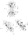
- the plate 10 shown has a straight portion 12 defining a longitudinal axis A P .
- the straight portion 12 of the plate may be a portion of a diaphyseal plate for placement along the diaphysis of a long bone of an upper or lower extremity.
- the straight portion 12 may be one end of a metaphyseal plate for use at the end of a long bone.
- the straight portion 12 may be a segment of any other plate having an elongate portion.
- the plate 10 may be manufactured to assume other shapes that are suitable for use on various bones throughout the human body.
- the plate 10 is manufactured from metal, and more preferably machined from a solid block of titanium or titanium alloy.
- the plate 10 has an upper surface 14, a bone contacting lower surface 16 and a thickness T defined between the upper and lower surfaces 14, 16.
- the plate optionally includes a plurality of significantly smaller and preferably cylindrical holes 23 that are sized to closely receive respective K-wires for temporary fixation during an implantation procedure.
- the plate is shown to include three types of screw holes: a threaded round locking hole 18, a non-threaded round compression hole 20, and a non-threaded oblong compression hole 22, each described further below. With respect to Figs.
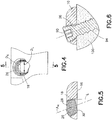
- the threaded screw hole 18 has threads 26 helically arranged about its interior, and the hole is preferably substantially uniform about its internal circumference.
- the hole 18 is tapered so as to have an upper opening 28 at or adjacent the upper surface 14 of the plate with a diameter D U larger than a diameter D L at a lower opening 30 at or adjacent the lower surface 16 of the plate.
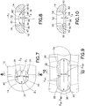
- the round compression screw hole 20 has an upper opening 32 at or adjacent the upper surface 14 of the plate 10 with a first diameter D 1 in each of two orthogonal directions and a lower opening 38 is provided at or adjacent the lower surface 16 of the plate with a smaller second diameter D 2 in one direction and the first diameter D 1 in a direction orthogonal to the second diameter D 2 .
- the first diameter D 1 is preferably larger than the diameter D U of the upper opening of the threaded screw hole.
- the second diameter D 2 is preferably smaller than the diameter D L of the lower opening of the threaded screw hole 18.
- the screw hole 20 has a central axis A C extending through the centers of the upper and lower openings 32,38.
- two parallel rails 40 recessed relative to the upper opening 38 extend across the screw hole.
- the upper surfaces 42 of the rails 40 are angled relative to each other at approximately 60°-90° and together define a screw seat 34.
- Vertically extending walls 44 of the rails 40 define a lower portion 36 of the screw hole and have a thickness T R extending in the same direction as the central axis of the compression screw hole 20.
- the rails 40 extend parallel to the longitudinal axis A P of the plate 10 ( Fig. 1 ).
- the oblong compression screw hole 22 is substantially similar to the round compression screw hole, but extended in diameter; i.e., length, along the dimension in which the rails extend; that is, the screw hole 22 does not have the same D 1 diameter at two relatively orthogonal directions.
- screw hole 22 has an upper opening 52 with first major diameter D M1 and a first minor diameter D m1 , and a lower opening or slot 58 with a second major diameter D M2 and a second minor diameter D m2 .
- the first and second major diameters D M1 and D M2 are preferably of a common dimension, with the rails 60, and thus the seat 54, extending on laterally opposite sides of the first and second major diameters D M1 and D M2 , but not at the ends of the first and second major diameters.
- the second minor diameter D m2 is smaller than the first minor diameter D m1 .
- Rails 60 extend lengthwise along the screw hole 22, parallel to but on opposite sides of the second major diameter D M2 , and in the first embodiment parallel to the longitudinal axis A P of the plate.
- the locking and compression holes 18, 20, 22 may be situated along the longitudinal axis A P , offset from the longitudinal axis, or provided in a combination of both on-axis and off-axis locations.
- the compression screw holes 20, 22 are situated in alignment with the longitudinal axis A P
- the threaded locking holes 18 are situated offset from the longitudinal axis.
- the threaded locking holes 18 are oriented along an axis A H at a transverse and preferably acute angle, e.g., 20° ⁇ 10°, relative to a line normal L to the lower surface 16 of the bone plate 10.
- the system also includes the single type of bone screw 24 that can be used in either the threaded screw hole 18 or non-threaded compression screw holes 20, 22 to (i) mechanically lock relative to the plate when the screw is inserted into the threaded locking hole, or (ii) axially load the plate 10 relative to bone when the screw is inserted into the compression screw holes.
- the screw 24, as described below, operates as a standard locking screw when inserted into the threaded screw hole 18.
- the screw 24 has structure that mates with the screw seats 34, 54 ( Figs.
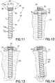
- the screw 24 has a head 82 and a shaft 84.
- the head 82 includes conically tapered external threads 86 terminating in an upper peripheral rim 88 at the trailing end of the threads that functions as a stop.
- the threads 86 preferably taper at 4° - 10° per side, more preferably at 6° per side.
- the head 82 also includes a driver engagement socket 90 for receiving a torque driver tool with a corresponding shape.
- the socket 90 may define a square or hexagonal cross-section ( Fig. 6 ).
- a bearing annulus 92 is provided at the transition of the head 82 to the shaft 84.
- the bearing annulus 92 is smaller than the threaded portion of the head and forms a preferably smooth 90° conical portion.
- the angle of the lower surface of the bearing annulus 92 presents a large surface area for the given diameter of the annulus and is advantageous in supporting high axial loads on the screw seats 34, 54 of the compression holes. Further, the bearing annulus 92 displaces the axially loads from the weaker portions of the screw head, particularly at the thinnest portion of the wall of the screw head between the driver socket 90 and the external threads 86, which could otherwise cause the screw to plastically deform and potentially fail.
- the shaft 84 has bone engaging threads 94 which define a shaft major diameter D SM , a shaft minor diameter D Sm , a shaft thread pitch S P .
- the shaft thread pitch S P is approximate to, but greater than, the thickness T R of the vertical walls 44, 64 of the compression screw holes 20, 22.
- the shaft 84 of the screw in view of the relationship of the dimensions of the components, the shaft 84 of the screw must be rotationally thread through the lowermost opening 38 of the compression screw hole 20 to be longitudinally advanced therethrough. This is transparent to the user, as the screw shaft 84 is being simultaneously threaded through bone 100.
- Fig. 13 when the screw 24 is advanced such that the bearing annulus 92 of the head contacts the screw seat 34, further torqueing of the screw causes the load to be carried on the screw at the bearing annulus. As shown in Fig.
- the compression screw hole can also accommodate approximately 2° - 3° of lateral angulation of the shaft 84 on each side of line normal L to the lower surface 16 of the plate (for a total of 4° - 6° of angular variability).
- the screw is inserted within the oblong screw hole in the same manner.
- the oblong screw hole provides the option to adjust the longitudinal displacement of the plate relative to the screw before the screw is fully loaded against the plate.
- the holes 18, 20, 22 and screw 24 are structured for clustering together on the bone plate.
- the screw head with the bearing annulus 92 located distally of the head threads 86, is of a particularly compact design. This permits more screw holes 18, 20, 22 sized to accommodate the screw to be formed in the plate 10 to provide the surgeon with greater flexibility of screw placement into a bone.
- the screw holes 18, 20, 22 can be spaced closer together in a cluster 96 to provide the advantages of placement on both plates of large and relatively small dimensions.
- a threaded hole 18 is located substantially equidistantly between two compression screw holes, and more preferably between a round compression screw hole 20 and an oblong compression screw hole 22.
- Such a cluster 96 preferably provides screw hole spacing in a dense pattern, wherein portions of each of a threaded hole 18 and the both types of the compression holes 20, 22 are located within a bounding area bounded by a circle preferably no larger than twice the diameter D U of the upper opening 28 of the threaded hole 18 (as shown at bounding area BA 1 ) or more preferably 1.5 diameters of the diameter D U of the upper opening 28 of the threaded hole 18 (as shown at bounding area BA 2 ) in Fig. 3 .
- each of the clusters as well as the indicated bounding areas preferably also includes a portion of at least one of the guidewire holes 23.
- Multiple clusters 96 of screw holes are preferably provided to the bone plate.
- the plate is positioned on the bone at a location suited for stabilization of the fracture.
- a hole is drilled through an oblong compression hole 22 in the plate and into the underlying bone, and a screw 24 is inserted into the hole.
- the screw shaft can and must be rotatably threaded through the wall portion 64 to advance the shaft 84 through the compression hole.
- the screw 24 is then driven to load the bearing annulus 92 against the screw seat 54 and thereby force the plate 10 and the bone against each other.
- 120 lbs of axial load can be generated between the bearing annulus 92 and the seat 54 with no load on or damage to the screw head threads 86.
- the bearing annulus 92 support the loads placed thereon without plastic deformation of the head.
- the shaft 84 is advanced through the threaded screw hole into an underlying drilled hole and the screw head 82 is threaded into locking engagement with the internal threads 26 of the screw hole.
- the shaft threads 94 retain bone and bone fragments 100 beneath the plate 10 and hold such bone and fragments in a stable and preferably fixed position relative to the plate.
- the design of the screw seat 54 of the oblong compression holes 22, with no seat portion located in alignment with the first and second major diameters D M1 , D M2 permits the oblong compression hole to be used in application of dynamic compression across a fracture.
- dynamic compression the plate is initially secured to the bone with one or more screws 24 only at one side of a fracture. Then, on the other side of the fracture, a screw 24 is inserted at the end of an oblong screw hole located further from the fracture.
- a bone plate system may include a second embodiment of compression screw holes 120 for use in association with the screw 24.
- the round compression screw hole 120 includes a conically shaped hole 121 with an upper opening 132 with a first diameter and a lower opening 138 with a second diameter.
- the screw hole is deeper to accommodate the rim 88 of the screw head 82.
- the round compression hole has a single rail 140 extending from one side thereof below the upper opening 132 to define screw seat 134 and a lower portion 136.
- the lower opening defines a slot 146 adjacent the rail 140.
- the second embodiment of the oblong screw hole 122 is of similar design, with one upper diameter larger than an orthogonal upper diameter.
- the second embodiment of the compression screw holes 120 provides for a screw seat 134 for supporting the bearing annulus 92 of the screw 24 only at one side of the screw hole 122. Constraining the angle of the screw by the provision of a conical hole ensures that the bearing annulus applies the load to the screw seat.
- the second diameter of the lower opening 138 (or second minor diameter of an oblong compression screw hole) continues to be smaller than the screw shaft major diameter and larger than the screw shaft minor diameter D SM (for reference see Fig. 11 ).
- the lower portion 136 defined by the rail 140 has a thickness T R along vertical wall 144 that is smaller than the pitch S P of the screw shaft threads. As such, the screw shaft 94 can and must be inserted through the lower opening 138 of the compression hole by rotational advancement.
- the system allows a single type of screw to be used in association with a plate to provide for axial loading of the plate to the bone at compression holes and locking fixation of the screws to the plate at locking holes.
- the system reduces the inventory of components required for a surgical plating procedure.
- the system simplifies the procedure, as the surgeon is able to use the same screw regardless of the type of screw fixation required.
- the system is particularly well adapted to plates and screws of small dimensions, such as screws at or smaller than 3.5 mm, or more particularly at or smaller than 2.7 mm, and is capable of providing high axial loads, on the order of 120 lbs of axial load, without significant plastic deformation between the screw and plate.
Landscapes
- Health & Medical Sciences (AREA)
- Orthopedic Medicine & Surgery (AREA)
- Surgery (AREA)
- Life Sciences & Earth Sciences (AREA)
- Heart & Thoracic Surgery (AREA)
- Nuclear Medicine, Radiotherapy & Molecular Imaging (AREA)
- Engineering & Computer Science (AREA)
- Biomedical Technology (AREA)
- Neurology (AREA)
- Medical Informatics (AREA)
- Molecular Biology (AREA)
- Animal Behavior & Ethology (AREA)
- General Health & Medical Sciences (AREA)
- Public Health (AREA)
- Veterinary Medicine (AREA)
- Surgical Instruments (AREA)
Applications Claiming Priority (3)
| Application Number | Priority Date | Filing Date | Title |
|---|---|---|---|
| US13/313,350 US8632574B2 (en) | 2011-12-07 | 2011-12-07 | Reduced component bone plating system |
| EP12812761.0A EP2787911B1 (de) | 2011-12-07 | 2012-12-03 | Knochenplattensystem mit verringerter komponentenzahl |
| PCT/US2012/067558 WO2013085835A1 (en) | 2011-12-07 | 2012-12-03 | Reduced component bone plating system |
Related Parent Applications (1)
| Application Number | Title | Priority Date | Filing Date |
|---|---|---|---|
| EP12812761.0A Division EP2787911B1 (de) | 2011-12-07 | 2012-12-03 | Knochenplattensystem mit verringerter komponentenzahl |
Publications (3)
| Publication Number | Publication Date |
|---|---|
| EP3207887A2 true EP3207887A2 (de) | 2017-08-23 |
| EP3207887A3 EP3207887A3 (de) | 2017-09-13 |
| EP3207887B1 EP3207887B1 (de) | 2020-02-19 |
Family
ID=47521148
Family Applications (2)
| Application Number | Title | Priority Date | Filing Date |
|---|---|---|---|
| EP12812761.0A Active EP2787911B1 (de) | 2011-12-07 | 2012-12-03 | Knochenplattensystem mit verringerter komponentenzahl |
| EP16184396.6A Active EP3207887B1 (de) | 2011-12-07 | 2012-12-03 | Knochenplattensystem mit verringerter komponentenzahl |
Family Applications Before (1)
| Application Number | Title | Priority Date | Filing Date |
|---|---|---|---|
| EP12812761.0A Active EP2787911B1 (de) | 2011-12-07 | 2012-12-03 | Knochenplattensystem mit verringerter komponentenzahl |
Country Status (3)
| Country | Link |
|---|---|
| US (2) | US8632574B2 (de) |
| EP (2) | EP2787911B1 (de) |
| WO (1) | WO2013085835A1 (de) |
Families Citing this family (54)
| Publication number | Priority date | Publication date | Assignee | Title |
|---|---|---|---|---|
| US10251757B2 (en) * | 2008-09-17 | 2019-04-09 | Skeletal Dynamics Llc | Grooved slot allowing adjustment of the position of a bone fixation device for osteosynthesis |
| US8632574B2 (en) * | 2011-12-07 | 2014-01-21 | Biomet C.V. | Reduced component bone plating system |
| US8790378B2 (en) | 2012-02-02 | 2014-07-29 | Biomet C.V. | Distal radius fracture fixation plate with integrated and adjustable volar ulnar facet support |
| EP2852342A4 (de) * | 2012-05-22 | 2016-01-06 | Austofix Group Ltd | Vorrichtung zur knochenfixation |
| US9468479B2 (en) | 2013-09-06 | 2016-10-18 | Cardinal Health 247, Inc. | Bone plate |
| US10226287B2 (en) | 2014-03-31 | 2019-03-12 | Association For The Advancement Of Musculoskeletal | Bone plate with versatile screw holes |
| US9730686B2 (en) | 2014-09-03 | 2017-08-15 | Biomet C.V. | System and method of soft tissue anchoring to metaphyseal bone plate |
| US9936990B2 (en) | 2015-02-17 | 2018-04-10 | Biomet C.V. | Bone peg having improved extraction |
| CN104739497A (zh) * | 2015-04-02 | 2015-07-01 | 王维山 | 一种带记忆合金的解剖型锁定钩板 |
| US11197682B2 (en) | 2015-08-27 | 2021-12-14 | Globus Medical, Inc. | Proximal humeral stabilization system |
| US11076898B2 (en) | 2015-08-27 | 2021-08-03 | Globus Medical, Inc. | Proximal humeral stabilization system |
| US10687874B2 (en) | 2015-08-27 | 2020-06-23 | Globus Medical, Inc | Proximal humeral stabilization system |
| US10130402B2 (en) | 2015-09-25 | 2018-11-20 | Globus Medical, Inc. | Bone fixation devices having a locking feature |
| US11020157B2 (en) | 2015-10-05 | 2021-06-01 | Arthrex, Inc. | Surgical screw system |
| US9974581B2 (en) | 2015-11-20 | 2018-05-22 | Globus Medical, Inc. | Expandable intramedullary systems and methods of using the same |
| US10939943B2 (en) | 2016-01-04 | 2021-03-09 | OsteoCertus, LLC | Orthopedic bone plate system |
| US10478237B2 (en) | 2016-01-04 | 2019-11-19 | OsteoCertus, LLC | Orthopedic bone plate system |
| US10258402B2 (en) | 2016-01-04 | 2019-04-16 | OsteoCertus, LLC | Orthopedic bone plate system |
| US9795411B2 (en) | 2016-03-02 | 2017-10-24 | Globus Medical, Inc. | Fixators for bone stabilization and associated systems and methods |
| US10531905B2 (en) | 2016-04-19 | 2020-01-14 | Globus Medical, Inc. | Implantable compression screws |
| FR3052047B1 (fr) | 2016-06-02 | 2021-12-17 | Neosteo | Dispositif medical implantable pour la solidarisation de parties osseuses separees en vue de leur fusion |
| US11331128B2 (en) | 2016-08-17 | 2022-05-17 | Globus Medical Inc. | Distal radius stabilization system |
| US12588937B2 (en) | 2016-08-17 | 2026-03-31 | Globus Medical, Inc. | Volar distal radius stabilization system |
| US11432857B2 (en) | 2016-08-17 | 2022-09-06 | Globus Medical, Inc. | Stabilization systems |
| US10751098B2 (en) | 2016-08-17 | 2020-08-25 | Globus Medical Inc. | Stabilization systems |
| US10687873B2 (en) | 2016-08-17 | 2020-06-23 | Globus Medical Inc. | Stabilization systems |
| US11141204B2 (en) | 2016-08-17 | 2021-10-12 | Globus Medical Inc. | Wrist stabilization systems |
| US10420596B2 (en) | 2016-08-17 | 2019-09-24 | Globus Medical, Inc. | Volar distal radius stabilization system |
| US11197701B2 (en) | 2016-08-17 | 2021-12-14 | Globus Medical, Inc. | Stabilization systems |
| US10575884B2 (en) | 2016-08-17 | 2020-03-03 | Globus Medical, Inc. | Fracture plates, systems, and methods |
| US10383668B2 (en) | 2016-08-17 | 2019-08-20 | Globus Medical, Inc. | Volar distal radius stabilization system |
| US11213327B2 (en) | 2016-08-17 | 2022-01-04 | Globus Medical, Inc. | Fracture plates, systems, and methods |
| US10299847B2 (en) | 2016-09-22 | 2019-05-28 | Globus Medical, Inc. | Systems and methods for intramedullary nail implantation |
| US10881438B2 (en) | 2017-03-10 | 2021-01-05 | Globus Medical, Inc. | Clavicle fixation system |
| US10368928B2 (en) | 2017-03-13 | 2019-08-06 | Globus Medical, Inc. | Bone stabilization systems |
| US10905477B2 (en) | 2017-03-13 | 2021-02-02 | Globus Medical, Inc. | Bone stabilization systems |
| US11096730B2 (en) | 2017-09-13 | 2021-08-24 | Globus Medical Inc. | Bone stabilization systems |
| US12279795B2 (en) | 2017-09-13 | 2025-04-22 | Globus Medical, Inc. | Bone stabilization systems |
| US10856920B2 (en) | 2017-09-13 | 2020-12-08 | Globus Medical Inc. | Bone stabilization systems |
| US11224468B2 (en) | 2018-03-02 | 2022-01-18 | Globus Medical, Inc. | Distal tibial plating system |
| EP4108194B1 (de) | 2018-03-02 | 2025-10-29 | Stryker European Operations Limited | Knochenplatten und zugehörige schrauben |
| US11071570B2 (en) | 2018-03-02 | 2021-07-27 | Globus Medical, Inc. | Distal tibial plating system |
| US11141172B2 (en) | 2018-04-11 | 2021-10-12 | Globus Medical, Inc. | Method and apparatus for locking a drill guide in a polyaxial hole |
| US11202663B2 (en) | 2019-02-13 | 2021-12-21 | Globus Medical, Inc. | Proximal humeral stabilization systems and methods thereof |
| FR3092743B1 (fr) * | 2019-02-14 | 2021-11-12 | Newclip Int | Dispositif d’ostéosynthèse à plaque munie d’un orifice oblong pour la réception d’une vis de fixation |
| WO2020252166A1 (en) | 2019-06-12 | 2020-12-17 | Government Of The United States Of America As Represented By The Department Of Veterans Affairs | Femoral head arthroplasty system |
| US12185995B2 (en) | 2019-10-09 | 2025-01-07 | Globus Medical, Inc. | Bone stabilization systems |
| US11129627B2 (en) | 2019-10-30 | 2021-09-28 | Globus Medical, Inc. | Method and apparatus for inserting a bone plate |
| US11723647B2 (en) | 2019-12-17 | 2023-08-15 | Globus Medical, Inc. | Syndesmosis fixation assembly |
| US11957394B2 (en) | 2020-02-27 | 2024-04-16 | J.M. Longyear Manufacturing, Llc | Screw caddy |
| EP4436501A4 (de) * | 2021-11-22 | 2025-10-08 | Dynamic Spine Tech Llc | Befestigungsanordnungen für medizinische implantate |
| US12064150B2 (en) | 2022-01-19 | 2024-08-20 | Globus Medical Inc. | System and method for treating bone fractures |
| IT202200017211A1 (it) * | 2022-08-11 | 2024-02-11 | Limacorporate Spa | Piastra di ancoraggio osseo con vite compressiva, in particolare per baseplate di protesi di spalla |
| US12478365B2 (en) | 2022-08-24 | 2025-11-25 | Globus Medical, Inc. | Systems, devices and methods for implanting suture buttons |
Citations (1)
| Publication number | Priority date | Publication date | Assignee | Title |
|---|---|---|---|---|
| US20100069969A1 (en) | 2008-09-15 | 2010-03-18 | Ampuero Eduardo A | Low Profile Screw and Washer System for Bone Plating |
Family Cites Families (16)
| Publication number | Priority date | Publication date | Assignee | Title |
|---|---|---|---|---|
| IT1237496B (it) * | 1989-10-26 | 1993-06-08 | Giuseppe Vrespa | Dispositivo a vite per l'ancoraggio di protesi alle ossa, metodo per l'applicazione di tale dispositivo e relativa attrezzatura |
| KR100329539B1 (ko) * | 1995-03-27 | 2002-11-13 | 신테스 아게 츄어 | 뼈고정판 |
| US6129730A (en) * | 1999-02-10 | 2000-10-10 | Depuy Acromed, Inc. | Bi-fed offset pitch bone screw |
| EP1158915B1 (de) | 1999-03-09 | 2004-09-01 | SYNTHES AG Chur | Knochenplatte |
| ATE257674T1 (de) | 1999-09-13 | 2004-01-15 | Synthes Ag | Knochenplattenvorrichtung |
| DE19951760B4 (de) * | 1999-10-27 | 2005-06-09 | Sepitec Foundation | Implantat für Osteosynthesen |
| US7857838B2 (en) * | 2003-03-27 | 2010-12-28 | Depuy Products, Inc. | Anatomical distal radius fracture fixation plate |
| CN1764418B (zh) * | 2003-03-26 | 2010-05-26 | 瑞士整形外科技术股份有限公司 | 锁定接骨板 |
| US7951176B2 (en) * | 2003-05-30 | 2011-05-31 | Synthes Usa, Llc | Bone plate |
| US8105367B2 (en) | 2003-09-29 | 2012-01-31 | Smith & Nephew, Inc. | Bone plate and bone plate assemblies including polyaxial fasteners |
| US20050192578A1 (en) * | 2004-02-26 | 2005-09-01 | Horst Steven P. | Bone plates with locking apertures |
| WO2008007194A2 (en) * | 2006-07-07 | 2008-01-17 | Precimed, S.A. | Bone plate with complex, adjacent holes joined by a bend relief zone |
| RU2012115476A (ru) * | 2009-09-18 | 2013-10-27 | Biomet C.V. | Одноразовый набор и компоненты для хирургической ортопедии |
| EP2389884B1 (de) * | 2010-05-25 | 2013-07-31 | Stryker Trauma SA | Implantat zur Knochenfixierung |
| US8632574B2 (en) * | 2011-12-07 | 2014-01-21 | Biomet C.V. | Reduced component bone plating system |
| US9987061B2 (en) * | 2014-01-28 | 2018-06-05 | Biomet C.V. | Implant with suspended locking holes |
-
2011
- 2011-12-07 US US13/313,350 patent/US8632574B2/en not_active Expired - Fee Related
-
2012
- 2012-12-03 EP EP12812761.0A patent/EP2787911B1/de active Active
- 2012-12-03 EP EP16184396.6A patent/EP3207887B1/de active Active
- 2012-12-03 WO PCT/US2012/067558 patent/WO2013085835A1/en not_active Ceased
-
2013
- 2013-09-30 US US14/041,437 patent/US9474558B2/en active Active
Patent Citations (1)
| Publication number | Priority date | Publication date | Assignee | Title |
|---|---|---|---|---|
| US20100069969A1 (en) | 2008-09-15 | 2010-03-18 | Ampuero Eduardo A | Low Profile Screw and Washer System for Bone Plating |
Also Published As
| Publication number | Publication date |
|---|---|
| US8632574B2 (en) | 2014-01-21 |
| WO2013085835A1 (en) | 2013-06-13 |
| EP3207887B1 (de) | 2020-02-19 |
| US20130150901A1 (en) | 2013-06-13 |
| US9474558B2 (en) | 2016-10-25 |
| US20140031879A1 (en) | 2014-01-30 |
| EP2787911A1 (de) | 2014-10-15 |
| EP3207887A3 (de) | 2017-09-13 |
| EP2787911B1 (de) | 2016-08-17 |
Similar Documents
| Publication | Publication Date | Title |
|---|---|---|
| EP3207887B1 (de) | Knochenplattensystem mit verringerter komponentenzahl | |
| US8911443B2 (en) | Plate holder for manipulating bone plate | |
| US9867643B2 (en) | Polyaxial locking mechanism | |
| US10918430B2 (en) | Bone screw with multiple thread profiles for far cortical locking and flexible engagement to a bone | |
| US8518090B2 (en) | Fastener with serrated thread for attachment to a bone plate at a selectable angle | |
| US7695502B2 (en) | Bone stabilization system including plate having fixed-angle holes together with unidirectional locking screws and surgeon-directed locking screws | |
| EP1996120B1 (de) | Knochenstabilisierungssystem mit multidirektionalem gewindefixierelement | |
| AU2008231166B2 (en) | Passive screw locking mechanism | |
| US20130289447A1 (en) | Method of Using a Drill Sleeve (as amended) | |
| AU2009305691A1 (en) | Angulated locking plate/screw interface |
Legal Events
| Date | Code | Title | Description |
|---|---|---|---|
| PUAI | Public reference made under article 153(3) epc to a published international application that has entered the european phase |
Free format text: ORIGINAL CODE: 0009012 |
|
| STAA | Information on the status of an ep patent application or granted ep patent |
Free format text: STATUS: THE APPLICATION HAS BEEN PUBLISHED |
|
| PUAL | Search report despatched |
Free format text: ORIGINAL CODE: 0009013 |
|
| AC | Divisional application: reference to earlier application |
Ref document number: 2787911 Country of ref document: EP Kind code of ref document: P |
|
| AK | Designated contracting states |
Kind code of ref document: A2 Designated state(s): AL AT BE BG CH CY CZ DE DK EE ES FI FR GB GR HR HU IE IS IT LI LT LU LV MC MK MT NL NO PL PT RO RS SE SI SK SM TR |
|
| AK | Designated contracting states |
Kind code of ref document: A3 Designated state(s): AL AT BE BG CH CY CZ DE DK EE ES FI FR GB GR HR HU IE IS IT LI LT LU LV MC MK MT NL NO PL PT RO RS SE SI SK SM TR |
|
| RIC1 | Information provided on ipc code assigned before grant |
Ipc: A61B 17/80 20060101AFI20170809BHEP Ipc: A61B 17/86 20060101ALI20170809BHEP |
|
| STAA | Information on the status of an ep patent application or granted ep patent |
Free format text: STATUS: REQUEST FOR EXAMINATION WAS MADE |
|
| 17P | Request for examination filed |
Effective date: 20180313 |
|
| RBV | Designated contracting states (corrected) |
Designated state(s): AL AT BE BG CH CY CZ DE DK EE ES FI FR GB GR HR HU IE IS IT LI LT LU LV MC MK MT NL NO PL PT RO RS SE SI SK SM TR |
|
| GRAP | Despatch of communication of intention to grant a patent |
Free format text: ORIGINAL CODE: EPIDOSNIGR1 |
|
| STAA | Information on the status of an ep patent application or granted ep patent |
Free format text: STATUS: GRANT OF PATENT IS INTENDED |
|
| INTG | Intention to grant announced |
Effective date: 20190902 |
|
| GRAS | Grant fee paid |
Free format text: ORIGINAL CODE: EPIDOSNIGR3 |
|
| GRAA | (expected) grant |
Free format text: ORIGINAL CODE: 0009210 |
|
| STAA | Information on the status of an ep patent application or granted ep patent |
Free format text: STATUS: THE PATENT HAS BEEN GRANTED |
|
| AC | Divisional application: reference to earlier application |
Ref document number: 2787911 Country of ref document: EP Kind code of ref document: P |
|
| AK | Designated contracting states |
Kind code of ref document: B1 Designated state(s): AL AT BE BG CH CY CZ DE DK EE ES FI FR GB GR HR HU IE IS IT LI LT LU LV MC MK MT NL NO PL PT RO RS SE SI SK SM TR |
|
| REG | Reference to a national code |
Ref country code: CH Ref legal event code: NV Representative=s name: MICHELI AND CIE SA, CH Ref country code: CH Ref legal event code: EP |
|
| REG | Reference to a national code |
Ref country code: DE Ref legal event code: R096 Ref document number: 602012067986 Country of ref document: DE |
|
| REG | Reference to a national code |
Ref country code: AT Ref legal event code: REF Ref document number: 1234048 Country of ref document: AT Kind code of ref document: T Effective date: 20200315 |
|
| REG | Reference to a national code |
Ref country code: IE Ref legal event code: FG4D |
|
| REG | Reference to a national code |
Ref country code: NL Ref legal event code: MP Effective date: 20200219 |
|
| PG25 | Lapsed in a contracting state [announced via postgrant information from national office to epo] |
Ref country code: FI Free format text: LAPSE BECAUSE OF FAILURE TO SUBMIT A TRANSLATION OF THE DESCRIPTION OR TO PAY THE FEE WITHIN THE PRESCRIBED TIME-LIMIT Effective date: 20200219 Ref country code: NO Free format text: LAPSE BECAUSE OF FAILURE TO SUBMIT A TRANSLATION OF THE DESCRIPTION OR TO PAY THE FEE WITHIN THE PRESCRIBED TIME-LIMIT Effective date: 20200519 Ref country code: RS Free format text: LAPSE BECAUSE OF FAILURE TO SUBMIT A TRANSLATION OF THE DESCRIPTION OR TO PAY THE FEE WITHIN THE PRESCRIBED TIME-LIMIT Effective date: 20200219 |
|
| REG | Reference to a national code |
Ref country code: LT Ref legal event code: MG4D |
|
| PG25 | Lapsed in a contracting state [announced via postgrant information from national office to epo] |
Ref country code: BG Free format text: LAPSE BECAUSE OF FAILURE TO SUBMIT A TRANSLATION OF THE DESCRIPTION OR TO PAY THE FEE WITHIN THE PRESCRIBED TIME-LIMIT Effective date: 20200519 Ref country code: GR Free format text: LAPSE BECAUSE OF FAILURE TO SUBMIT A TRANSLATION OF THE DESCRIPTION OR TO PAY THE FEE WITHIN THE PRESCRIBED TIME-LIMIT Effective date: 20200520 Ref country code: HR Free format text: LAPSE BECAUSE OF FAILURE TO SUBMIT A TRANSLATION OF THE DESCRIPTION OR TO PAY THE FEE WITHIN THE PRESCRIBED TIME-LIMIT Effective date: 20200219 Ref country code: LV Free format text: LAPSE BECAUSE OF FAILURE TO SUBMIT A TRANSLATION OF THE DESCRIPTION OR TO PAY THE FEE WITHIN THE PRESCRIBED TIME-LIMIT Effective date: 20200219 Ref country code: SE Free format text: LAPSE BECAUSE OF FAILURE TO SUBMIT A TRANSLATION OF THE DESCRIPTION OR TO PAY THE FEE WITHIN THE PRESCRIBED TIME-LIMIT Effective date: 20200219 Ref country code: IS Free format text: LAPSE BECAUSE OF FAILURE TO SUBMIT A TRANSLATION OF THE DESCRIPTION OR TO PAY THE FEE WITHIN THE PRESCRIBED TIME-LIMIT Effective date: 20200619 |
|
| PG25 | Lapsed in a contracting state [announced via postgrant information from national office to epo] |
Ref country code: NL Free format text: LAPSE BECAUSE OF FAILURE TO SUBMIT A TRANSLATION OF THE DESCRIPTION OR TO PAY THE FEE WITHIN THE PRESCRIBED TIME-LIMIT Effective date: 20200219 |
|
| REG | Reference to a national code |
Ref country code: DE Ref legal event code: R082 Ref document number: 602012067986 Country of ref document: DE Representative=s name: VENNER SHIPLEY GERMANY LLP, DE Ref country code: DE Ref legal event code: R082 Ref document number: 602012067986 Country of ref document: DE Representative=s name: VENNER SHIPLEY LLP, DE |
|
| PG25 | Lapsed in a contracting state [announced via postgrant information from national office to epo] |
Ref country code: SK Free format text: LAPSE BECAUSE OF FAILURE TO SUBMIT A TRANSLATION OF THE DESCRIPTION OR TO PAY THE FEE WITHIN THE PRESCRIBED TIME-LIMIT Effective date: 20200219 Ref country code: PT Free format text: LAPSE BECAUSE OF FAILURE TO SUBMIT A TRANSLATION OF THE DESCRIPTION OR TO PAY THE FEE WITHIN THE PRESCRIBED TIME-LIMIT Effective date: 20200712 Ref country code: CZ Free format text: LAPSE BECAUSE OF FAILURE TO SUBMIT A TRANSLATION OF THE DESCRIPTION OR TO PAY THE FEE WITHIN THE PRESCRIBED TIME-LIMIT Effective date: 20200219 Ref country code: RO Free format text: LAPSE BECAUSE OF FAILURE TO SUBMIT A TRANSLATION OF THE DESCRIPTION OR TO PAY THE FEE WITHIN THE PRESCRIBED TIME-LIMIT Effective date: 20200219 Ref country code: SM Free format text: LAPSE BECAUSE OF FAILURE TO SUBMIT A TRANSLATION OF THE DESCRIPTION OR TO PAY THE FEE WITHIN THE PRESCRIBED TIME-LIMIT Effective date: 20200219 Ref country code: EE Free format text: LAPSE BECAUSE OF FAILURE TO SUBMIT A TRANSLATION OF THE DESCRIPTION OR TO PAY THE FEE WITHIN THE PRESCRIBED TIME-LIMIT Effective date: 20200219 Ref country code: LT Free format text: LAPSE BECAUSE OF FAILURE TO SUBMIT A TRANSLATION OF THE DESCRIPTION OR TO PAY THE FEE WITHIN THE PRESCRIBED TIME-LIMIT Effective date: 20200219 Ref country code: DK Free format text: LAPSE BECAUSE OF FAILURE TO SUBMIT A TRANSLATION OF THE DESCRIPTION OR TO PAY THE FEE WITHIN THE PRESCRIBED TIME-LIMIT Effective date: 20200219 Ref country code: ES Free format text: LAPSE BECAUSE OF FAILURE TO SUBMIT A TRANSLATION OF THE DESCRIPTION OR TO PAY THE FEE WITHIN THE PRESCRIBED TIME-LIMIT Effective date: 20200219 |
|
| REG | Reference to a national code |
Ref country code: AT Ref legal event code: MK05 Ref document number: 1234048 Country of ref document: AT Kind code of ref document: T Effective date: 20200219 |
|
| REG | Reference to a national code |
Ref country code: DE Ref legal event code: R097 Ref document number: 602012067986 Country of ref document: DE |
|
| PLBE | No opposition filed within time limit |
Free format text: ORIGINAL CODE: 0009261 |
|
| STAA | Information on the status of an ep patent application or granted ep patent |
Free format text: STATUS: NO OPPOSITION FILED WITHIN TIME LIMIT |
|
| 26N | No opposition filed |
Effective date: 20201120 |
|
| PG25 | Lapsed in a contracting state [announced via postgrant information from national office to epo] |
Ref country code: AT Free format text: LAPSE BECAUSE OF FAILURE TO SUBMIT A TRANSLATION OF THE DESCRIPTION OR TO PAY THE FEE WITHIN THE PRESCRIBED TIME-LIMIT Effective date: 20200219 Ref country code: IT Free format text: LAPSE BECAUSE OF FAILURE TO SUBMIT A TRANSLATION OF THE DESCRIPTION OR TO PAY THE FEE WITHIN THE PRESCRIBED TIME-LIMIT Effective date: 20200219 |
|
| PG25 | Lapsed in a contracting state [announced via postgrant information from national office to epo] |
Ref country code: SI Free format text: LAPSE BECAUSE OF FAILURE TO SUBMIT A TRANSLATION OF THE DESCRIPTION OR TO PAY THE FEE WITHIN THE PRESCRIBED TIME-LIMIT Effective date: 20200219 Ref country code: PL Free format text: LAPSE BECAUSE OF FAILURE TO SUBMIT A TRANSLATION OF THE DESCRIPTION OR TO PAY THE FEE WITHIN THE PRESCRIBED TIME-LIMIT Effective date: 20200219 |
|
| PG25 | Lapsed in a contracting state [announced via postgrant information from national office to epo] |
Ref country code: MC Free format text: LAPSE BECAUSE OF FAILURE TO SUBMIT A TRANSLATION OF THE DESCRIPTION OR TO PAY THE FEE WITHIN THE PRESCRIBED TIME-LIMIT Effective date: 20200219 |
|
| REG | Reference to a national code |
Ref country code: BE Ref legal event code: MM Effective date: 20201231 |
|
| PG25 | Lapsed in a contracting state [announced via postgrant information from national office to epo] |
Ref country code: LU Free format text: LAPSE BECAUSE OF NON-PAYMENT OF DUE FEES Effective date: 20201203 Ref country code: IE Free format text: LAPSE BECAUSE OF NON-PAYMENT OF DUE FEES Effective date: 20201203 |
|
| PG25 | Lapsed in a contracting state [announced via postgrant information from national office to epo] |
Ref country code: TR Free format text: LAPSE BECAUSE OF FAILURE TO SUBMIT A TRANSLATION OF THE DESCRIPTION OR TO PAY THE FEE WITHIN THE PRESCRIBED TIME-LIMIT Effective date: 20200219 Ref country code: MT Free format text: LAPSE BECAUSE OF FAILURE TO SUBMIT A TRANSLATION OF THE DESCRIPTION OR TO PAY THE FEE WITHIN THE PRESCRIBED TIME-LIMIT Effective date: 20200219 Ref country code: CY Free format text: LAPSE BECAUSE OF FAILURE TO SUBMIT A TRANSLATION OF THE DESCRIPTION OR TO PAY THE FEE WITHIN THE PRESCRIBED TIME-LIMIT Effective date: 20200219 |
|
| PG25 | Lapsed in a contracting state [announced via postgrant information from national office to epo] |
Ref country code: MK Free format text: LAPSE BECAUSE OF FAILURE TO SUBMIT A TRANSLATION OF THE DESCRIPTION OR TO PAY THE FEE WITHIN THE PRESCRIBED TIME-LIMIT Effective date: 20200219 Ref country code: AL Free format text: LAPSE BECAUSE OF FAILURE TO SUBMIT A TRANSLATION OF THE DESCRIPTION OR TO PAY THE FEE WITHIN THE PRESCRIBED TIME-LIMIT Effective date: 20200219 |
|
| PG25 | Lapsed in a contracting state [announced via postgrant information from national office to epo] |
Ref country code: BE Free format text: LAPSE BECAUSE OF NON-PAYMENT OF DUE FEES Effective date: 20201231 |
|
| P01 | Opt-out of the competence of the unified patent court (upc) registered |
Effective date: 20230527 |
|
| REG | Reference to a national code |
Ref country code: DE Ref legal event code: R081 Ref document number: 602012067986 Country of ref document: DE Owner name: ZIMMER GMBH, CH Free format text: FORMER OWNER: BIOMET C.V., GIBRALTAR, GI |
|
| REG | Reference to a national code |
Ref country code: CH Ref legal event code: U11 Free format text: ST27 STATUS EVENT CODE: U-0-0-U10-U11 (AS PROVIDED BY THE NATIONAL OFFICE) Effective date: 20260101 |
|
| PGFP | Annual fee paid to national office [announced via postgrant information from national office to epo] |
Ref country code: DE Payment date: 20251112 Year of fee payment: 14 |
|
| PGFP | Annual fee paid to national office [announced via postgrant information from national office to epo] |
Ref country code: GB Payment date: 20251114 Year of fee payment: 14 |
|
| PGFP | Annual fee paid to national office [announced via postgrant information from national office to epo] |
Ref country code: FR Payment date: 20251112 Year of fee payment: 14 |
|
| PGFP | Annual fee paid to national office [announced via postgrant information from national office to epo] |
Ref country code: CH Payment date: 20260101 Year of fee payment: 14 |