EP3207890A1 - Dispositif d'alimentation électrique pour instrument de traitement à haute fréquence, système de traitement à haute fréquence, et procédé de commande pour instrument de traitement à haute fréquence - Google Patents
Dispositif d'alimentation électrique pour instrument de traitement à haute fréquence, système de traitement à haute fréquence, et procédé de commande pour instrument de traitement à haute fréquence Download PDFInfo
- Publication number
- EP3207890A1 EP3207890A1 EP16772098.6A EP16772098A EP3207890A1 EP 3207890 A1 EP3207890 A1 EP 3207890A1 EP 16772098 A EP16772098 A EP 16772098A EP 3207890 A1 EP3207890 A1 EP 3207890A1
- Authority
- EP
- European Patent Office
- Prior art keywords
- output
- high frequency
- supply device
- power supply
- electrode
- Prior art date
- Legal status (The legal status is an assumption and is not a legal conclusion. Google has not performed a legal analysis and makes no representation as to the accuracy of the status listed.)
- Withdrawn
Links
Images






Classifications
-
- A—HUMAN NECESSITIES
- A61—MEDICAL OR VETERINARY SCIENCE; HYGIENE
- A61B—DIAGNOSIS; SURGERY; IDENTIFICATION
- A61B18/00—Surgical instruments, devices or methods for transferring non-mechanical forms of energy to or from the body
- A61B18/04—Surgical instruments, devices or methods for transferring non-mechanical forms of energy to or from the body by heating
- A61B18/12—Surgical instruments, devices or methods for transferring non-mechanical forms of energy to or from the body by heating by passing a current through the tissue to be heated, e.g. high-frequency current
- A61B18/1206—Generators therefor
- A61B18/1233—Generators therefor with circuits for assuring patient safety
-
- A—HUMAN NECESSITIES
- A61—MEDICAL OR VETERINARY SCIENCE; HYGIENE
- A61B—DIAGNOSIS; SURGERY; IDENTIFICATION
- A61B18/00—Surgical instruments, devices or methods for transferring non-mechanical forms of energy to or from the body
- A61B18/04—Surgical instruments, devices or methods for transferring non-mechanical forms of energy to or from the body by heating
- A61B18/12—Surgical instruments, devices or methods for transferring non-mechanical forms of energy to or from the body by heating by passing a current through the tissue to be heated, e.g. high-frequency current
- A61B18/14—Probes or electrodes therefor
-
- A—HUMAN NECESSITIES
- A61—MEDICAL OR VETERINARY SCIENCE; HYGIENE
- A61B—DIAGNOSIS; SURGERY; IDENTIFICATION
- A61B18/00—Surgical instruments, devices or methods for transferring non-mechanical forms of energy to or from the body
- A61B18/04—Surgical instruments, devices or methods for transferring non-mechanical forms of energy to or from the body by heating
- A61B18/12—Surgical instruments, devices or methods for transferring non-mechanical forms of energy to or from the body by heating by passing a current through the tissue to be heated, e.g. high-frequency current
-
- A—HUMAN NECESSITIES
- A61—MEDICAL OR VETERINARY SCIENCE; HYGIENE
- A61B—DIAGNOSIS; SURGERY; IDENTIFICATION
- A61B18/00—Surgical instruments, devices or methods for transferring non-mechanical forms of energy to or from the body
- A61B18/04—Surgical instruments, devices or methods for transferring non-mechanical forms of energy to or from the body by heating
- A61B18/12—Surgical instruments, devices or methods for transferring non-mechanical forms of energy to or from the body by heating by passing a current through the tissue to be heated, e.g. high-frequency current
- A61B18/14—Probes or electrodes therefor
- A61B18/1402—Probes for open surgery
-
- G—PHYSICS
- G06—COMPUTING OR CALCULATING; COUNTING
- G06F—ELECTRIC DIGITAL DATA PROCESSING
- G06F1/00—Details not covered by groups G06F3/00 - G06F13/00 and G06F21/00
- G06F1/26—Power supply means, e.g. regulation thereof
- G06F1/266—Arrangements to supply power to external peripherals either directly from the computer or under computer control, e.g. supply of power through the communication port, computer controlled power-strips
-
- A—HUMAN NECESSITIES
- A61—MEDICAL OR VETERINARY SCIENCE; HYGIENE
- A61B—DIAGNOSIS; SURGERY; IDENTIFICATION
- A61B18/00—Surgical instruments, devices or methods for transferring non-mechanical forms of energy to or from the body
- A61B18/04—Surgical instruments, devices or methods for transferring non-mechanical forms of energy to or from the body by heating
-
- A—HUMAN NECESSITIES
- A61—MEDICAL OR VETERINARY SCIENCE; HYGIENE
- A61B—DIAGNOSIS; SURGERY; IDENTIFICATION
- A61B17/00—Surgical instruments, devices or methods
- A61B2017/00017—Electrical control of surgical instruments
- A61B2017/00022—Sensing or detecting at the treatment site
- A61B2017/00026—Conductivity or impedance, e.g. of tissue
-
- A—HUMAN NECESSITIES
- A61—MEDICAL OR VETERINARY SCIENCE; HYGIENE
- A61B—DIAGNOSIS; SURGERY; IDENTIFICATION
- A61B18/00—Surgical instruments, devices or methods for transferring non-mechanical forms of energy to or from the body
- A61B2018/00571—Surgical instruments, devices or methods for transferring non-mechanical forms of energy to or from the body for achieving a particular surgical effect
- A61B2018/00589—Coagulation
-
- A—HUMAN NECESSITIES
- A61—MEDICAL OR VETERINARY SCIENCE; HYGIENE
- A61B—DIAGNOSIS; SURGERY; IDENTIFICATION
- A61B18/00—Surgical instruments, devices or methods for transferring non-mechanical forms of energy to or from the body
- A61B2018/00636—Sensing and controlling the application of energy
- A61B2018/00642—Sensing and controlling the application of energy with feedback, i.e. closed loop control
-
- A—HUMAN NECESSITIES
- A61—MEDICAL OR VETERINARY SCIENCE; HYGIENE
- A61B—DIAGNOSIS; SURGERY; IDENTIFICATION
- A61B18/00—Surgical instruments, devices or methods for transferring non-mechanical forms of energy to or from the body
- A61B2018/00636—Sensing and controlling the application of energy
- A61B2018/00666—Sensing and controlling the application of energy using a threshold value
-
- A—HUMAN NECESSITIES
- A61—MEDICAL OR VETERINARY SCIENCE; HYGIENE
- A61B—DIAGNOSIS; SURGERY; IDENTIFICATION
- A61B18/00—Surgical instruments, devices or methods for transferring non-mechanical forms of energy to or from the body
- A61B2018/00636—Sensing and controlling the application of energy
- A61B2018/00696—Controlled or regulated parameters
- A61B2018/00702—Power or energy
-
- A—HUMAN NECESSITIES
- A61—MEDICAL OR VETERINARY SCIENCE; HYGIENE
- A61B—DIAGNOSIS; SURGERY; IDENTIFICATION
- A61B18/00—Surgical instruments, devices or methods for transferring non-mechanical forms of energy to or from the body
- A61B2018/00636—Sensing and controlling the application of energy
- A61B2018/00696—Controlled or regulated parameters
- A61B2018/00738—Depth, e.g. depth of ablation
-
- A—HUMAN NECESSITIES
- A61—MEDICAL OR VETERINARY SCIENCE; HYGIENE
- A61B—DIAGNOSIS; SURGERY; IDENTIFICATION
- A61B18/00—Surgical instruments, devices or methods for transferring non-mechanical forms of energy to or from the body
- A61B2018/00636—Sensing and controlling the application of energy
- A61B2018/00696—Controlled or regulated parameters
- A61B2018/00755—Resistance or impedance
-
- A—HUMAN NECESSITIES
- A61—MEDICAL OR VETERINARY SCIENCE; HYGIENE
- A61B—DIAGNOSIS; SURGERY; IDENTIFICATION
- A61B18/00—Surgical instruments, devices or methods for transferring non-mechanical forms of energy to or from the body
- A61B2018/00636—Sensing and controlling the application of energy
- A61B2018/00773—Sensed parameters
- A61B2018/00875—Resistance or impedance
-
- A—HUMAN NECESSITIES
- A61—MEDICAL OR VETERINARY SCIENCE; HYGIENE
- A61B—DIAGNOSIS; SURGERY; IDENTIFICATION
- A61B18/00—Surgical instruments, devices or methods for transferring non-mechanical forms of energy to or from the body
- A61B2018/00636—Sensing and controlling the application of energy
- A61B2018/00773—Sensed parameters
- A61B2018/00886—Duration
-
- A—HUMAN NECESSITIES
- A61—MEDICAL OR VETERINARY SCIENCE; HYGIENE
- A61B—DIAGNOSIS; SURGERY; IDENTIFICATION
- A61B18/00—Surgical instruments, devices or methods for transferring non-mechanical forms of energy to or from the body
- A61B2018/00636—Sensing and controlling the application of energy
- A61B2018/00904—Automatic detection of target tissue
-
- A—HUMAN NECESSITIES
- A61—MEDICAL OR VETERINARY SCIENCE; HYGIENE
- A61B—DIAGNOSIS; SURGERY; IDENTIFICATION
- A61B18/00—Surgical instruments, devices or methods for transferring non-mechanical forms of energy to or from the body
- A61B2018/00988—Means for storing information, e.g. calibration constants, or for preventing excessive use, e.g. usage, service life counter
-
- A—HUMAN NECESSITIES
- A61—MEDICAL OR VETERINARY SCIENCE; HYGIENE
- A61B—DIAGNOSIS; SURGERY; IDENTIFICATION
- A61B18/00—Surgical instruments, devices or methods for transferring non-mechanical forms of energy to or from the body
- A61B2018/00994—Surgical instruments, devices or methods for transferring non-mechanical forms of energy to or from the body combining two or more different kinds of non-mechanical energy or combining one or more non-mechanical energies with ultrasound
-
- A—HUMAN NECESSITIES
- A61—MEDICAL OR VETERINARY SCIENCE; HYGIENE
- A61B—DIAGNOSIS; SURGERY; IDENTIFICATION
- A61B5/00—Measuring for diagnostic purposes; Identification of persons
- A61B5/103—Measuring devices for testing the shape, pattern, colour, size or movement of the body or parts thereof, for diagnostic purposes
- A61B5/107—Measuring physical dimensions, e.g. size of the entire body or parts thereof
- A61B5/1076—Measuring physical dimensions, e.g. size of the entire body or parts thereof for measuring dimensions inside body cavities, e.g. using catheters
Definitions
- the present invention relates to a power supply device for a high frequency treatment instrument, a high frequency treatment system, and a control method for a high frequency treatment instrument.
- Jpn. Pat. Appln. KOKAI Publication No. 11-290334 discloses a monopolar-type electrical surgical apparatus which comprises an electrode-bearing handpiece and a return electrode and treats living tissue by causing a high frequency current to flow between the electrode of the handpiece and the return electrode.
- a preset electric power is output from a power supply device to the handpiece upon an operator pressing a push-button switch provided at part of the grip portion of the handpiece.
- a user turning on the output switch is not limited to only during the state where the electrode of the handpiece is in contact with living tissue as a treatment subject.
- a user may turn on the output switch before the electrode of the handpiece is brought in contact with the living tissue. It has been known that an unintentionally large electric discharge can occur when the distance between an electrode and living tissue reaches a particular distance, even before the start of treatment such as incision and hemostasis.
- the present invention purposes to provide a power supply device for a high frequency treatment instrument, a high frequency treatment system, and a control method for a high frequency treatment instrument, to control output while automatically predicting the contact between an electrode and living tissue.
- a power supply device is a power supply device for a high frequency treatment instrument which treats living tissue by supplying high frequency power to the living tissue using an electrode, the power supply device comprising: an output unit which supplies the high frequency power to the electrode; a distance information acquisition unit which acquires distance information for a distance between the living tissue and the electrode; a determination unit which determines whether the distance information satisfies a first condition or not; and an output control unit which controls the output unit so that output by the output unit is placed in a controlled state if the distance information satisfies the first condition and so that the output is set to a first output level higher than an output level in the controlled state if a second condition is satisfied after the output is placed in the controlled state.
- a high frequency treatment system comprises the power supply device and the high frequency treatment instrument.
- a control method for a high frequency treatment instrument is a method for controlling a high frequency treatment instrument which treats living tissue by supplying high frequency power to the living tissue using an electrode, the method comprising: supplying, by an output unit, the high frequency power to the electrode; acquiring, by a distance information acquisition unit, distance information for a distance between the living tissue and the electrode; determining, by a determination unit, whether the distance information satisfies a first condition or not; and controlling, by an output control unit, output of the high frequency power so that the output is placed in a controlled state if the distance information satisfies the first condition and so that the output is set to a first output level higher than an output level in the controlled state if a second condition is satisfied after the output is placed in the controlled state.
- the present invention can provide a power supply device for a high frequency treatment instrument, a high frequency treatment system, and a control method for a high frequency treatment instrument, which are capable of controlling while predicting the contact between an electrode and living tissue.
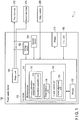
- FIG. 1 shows an overview of the configuration example of a high frequency treatment system 1 according to this embodiment.
- the high frequency treatment system 1 is a system for treating living tissue as a treatment subject using high frequency power.
- the high frequency treatment system 1 comprises a first electrode 212 and a second electrode 214.
- living tissue as a treatment subject will be placed between the first electrode 212 and the second electrode.
- a high frequency voltage between the first electrode 212 and the second electrode 214 By the application of a high frequency voltage between the first electrode 212 and the second electrode 214, a high frequency current flows through and generates heat in the living tissue as a treatment subject so that the treatment of the living tissue such as incision or coagulation is performed.
- the high frequency treatment system 1 comprises a power supply device 100 which supplies electric power between the first electrode 212 and the second electrode 214.
- the power supply device 100 comprises a controller 110, an output unit 140, a voltage sensor 152, a current sensor 154, a display 170, and an input unit 180.
- the controller 110 controls operations of each component of the power supply device 100.
- the controller 110 includes a microprocessor 111 which is, for example, a central processing unit (CPU) or an application specific integrated circuit (ASIC).
- the controller may be constituted by one CPU, etc. or a combination of multiple CPUs, ASICs, or the like.
- the controller operates in accordance with, for example, a program stored in a storage 122 described later.
- the output unit 140 outputs electric power supplied to the first electrode 212 and the second electrode 214 under the control of the controller 110.
- the electric power output from the output unit 140 is supplied to the first electrode 212 and the second electrode 214.
- the voltage sensor 152 acquires a voltage value at, for example, the output terminals of the power supply device 100.
- the voltage sensor 152 transmits the acquired voltage value to the controller 110.
- the current sensor 154 acquires a current value of an electric current output from, for example, the power supply device 100.
- the current sensor 154 transmits the acquired current value to the controller 110.
- the display 170 includes a display element.
- the display 170 displays various information concerning the power supply device 100.
- the input unit 180 includes a switch, a keyboard, a touch panel, etc. A user gives various inputs to the power supply device 100 using the input unit 180.
- the high frequency treatment system 1 further comprises an output switch 250.
- the output switch 250 is for switching on and off the output of the power supply device 100.
- the output switch 250 may be provided in a treatment instrument that comprises the first electrode 212, etc., or may be provided as a separate member from the treatment instrument, for example, as a foot switch.
- the microprocessor 111 of the controller 110 comprises a distance information acquisition unit 112, a determination unit 116, and an output control unit 118.
- the distance information acquisition unit 112 acquires distance information relating to the distance between living tissue as a treatment subject and an electrode, e.g., the first electrode 212.
- the distance information acquisition unit 112 includes an impedance acquisition unit 113.
- the impedance acquisition unit 113 calculates a value of impedance of, for example, a circuit including the first electrode 212 and the second electrode 214 based on the voltage value acquired by the voltage sensor 152 and the current value acquired by the current sensor 154. This impedance value can be used as an index of the distance between living tissue and an electrode, e.g., the first electrode 212.
- the determination unit 116 determines whether or not to temporarily reduce the output, as will be described later, based on the distance between living tissue and an electrode, e.g., the first electrode 212, of a treatment instrument, having been acquired by the distance information acquisition unit 112.
- the output control unit 118 controls electric power output from the output unit 140.
- the output control unit 118 includes a period adjustment unit 119.
- the period adjustment unit 119 adjusts a period for the temporal reduction of the output as above.
- the controller 110 also comprises the storage 122.
- the storage 122 stores, for example, programs and various parameters for the operations of the microprocessor 111. Also, the storage 122 temporarily stores information necessary for the calculations by the microprocessor 111.
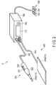
- FIG. 2 shows an external view of the configuration example of a high frequency treatment system including a monopolar-type high frequency treatment instrument.
- the high frequency treatment system 1 comprises the power supply device 100, a high frequency treatment instrument 220, a return electrode unit 240, and a foot switch 260.
- the high frequency treatment instrument 220 comprises an operation unit 222, an electrode 224, a first switch 227, a second switch 228, and a first cable 229.
- the operation unit 222 is a portion for a user to hold and to operate the high frequency treatment instrument 220.
- the first cable 229 connecting to the operation unit 222 is a cable for the connection between the high frequency treatment instrument 220 and the power supply device 100.
- the first switch 227 and the second switch 228 function as the output switch 250.
- the first switch 227 and the second switch 228 are provided at the operation unit 222.
- the electrode 224 is provided at the distal end of the operation unit 222. This electrode 224 functions as the first electrode 212 described above. During treatment, the electrode 224 is applied to living tissue as a treatment subject.
- the return electrode unit 240 comprises a return electrode 242 and a second cable 244.
- the return electrode 242 functions as the second electrode 214 described above.
- the second cable 244 is a cable for the connection between the return electrode 242 and the power supply device 100.
- the return electrode 242 is affixed to a body surface of a person to be treated.
- the first switch 227 of the high frequency treatment instrument 220 is a switch for an input to cause the power supply device 100 to output in an incision mode.
- the incision mode is a mode to burn and cut living tissue as a treatment subject at the portion contacting the electrode 224, with a supply of a relatively large electric power.
- the second switch 228 is a switch for an input to cause the power supply device 100 to output in a hemostasis mode.
- the hemostasis mode is a mode to perform hemostatic treatment, with a supply of lower electric power than in the incision mode, by burning and cutting living tissue as a treatment subject while denaturalizing an end section thereof at the portion contacting the electrode 224.
- the foot switch 260 comprises a first switch 262 and a second switch 264.
- the first switch 262 of the foot switch 260 has the same function as the first switch 227 provided at the high frequency treatment instrument 220.
- the second switch 264 of the foot switch 260 has the same function as the second switch 228 provided at the high frequency treatment instrument 220.
- a user can perform on/off switching of the output of the high frequency treatment instrument 220 using the first switch 227 and the second switch 228 provided at the high frequency treatment instrument, and also using the first switch 262 and the second switch 264 of the foot switch 260.
- the power supply device 100 is provided with a display panel 172 and switches 184.
- the display panel 172 functions as the display 170 described above. That is, it displays various information concerning the state of the power supply device 100.
- the switches 184 function as the input unit 180 described above. That is, a user uses the switches 184 to input, for example, a setup value for the output such as output electric power, a setup value to define cutting performance called an effect, and so on, to the power supply device 100.
- the high frequency treatment system 1 When the high frequency treatment system 1 is in use, a user as an operator brings the electrode 224 into contact with a treatment subject site while, for example, pressing down the first switch 227 or the second switch 228 of the high frequency treatment instrument 220. At this time, an electric current output from the power supply device 100 flows between the electrode 224 and the return electrode 242, causing the living tissue to be cut at the portion contacting the electrode 224.
- FIG. 3 illustrates a relationship between time and impedance when the first electrode 212 that is, for example, an electrode of a monopolar-type high frequency treatment instrument, gradually approaches living tissue as a treatment subject and makes contact with the living tissue while a high frequency voltage is applied between electrodes.
- the first electrode 212 that is, for example, an electrode of a monopolar-type high frequency treatment instrument
- FIG. 4A there is a sufficient distance between living tissue 900 and the first electrode 212 as shown in FIG. 4A .
- impedance takes a value under an open condition.
- the first electrode 212 approaches the living tissue 900 and an electric discharge occurs between the first electrode 212 and the living tissue 900.
- the acquired impedance falls below the impedance measured during the period indicated as (A) in FIG. 3 .
- FIG. 4B schematically shows the state at a certain time point included in the period indicated as (B) in FIG. 3 .
- an electric discharge is recognized.
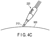
- the first electrode 212 contacts the living tissue 900 as shown in FIG. 4C .
- the impedance value becomes relatively low.
- control can be rendered unstable for the unintentional occurrence of excessive output current flow, or the like. Accordingly, in this embodiment, the output is halted for a portion of the period indicated as (B) in FIG. 3 .
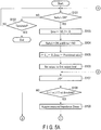
- step S101 the controller 110 determines whether the output switch 250 for the on/off instruction of the output is turned on or not. If it is not on, the processing proceeds to step S102. At step S102, it is determined whether or not the processing is terminated, for example, the main power is shut off. If termination is determined, the processing ends. On the other hand, if termination is not determined, the processing returns to step S101. That is, for the off period of the output switch 250, the processing repeats step S101 and step S102 for standby. On the other hand, if it is determined at step S101 that the output switch is on, the processing proceeds to step S103.
- the controller 110 sets information about the presence of an error to No and sets a determination flag f to 0.
- the information about the presence of an error and the value of the determination flag f are stored in the storage 122.
- step S104 to step S119 is repetitive processing.
- the condition for repeating is that the output switch 250 is on and there are no errors.
- the processing comes out of this repetitive processing and proceeds to step S120.
- the controller 110 initializes variables stored in the storage 122. In other words, it sets a later-described first counter i for measuring a blanking period to 0. It also sets a later-described second counter j for measuring a runtime error to 0. It also sets a later-described maximum value Zmax of impedance to a provisional value.
- the provisional value here is preferably a value which is sufficiently smaller than a value expected to be the maximum value Zmax.
- the controller 110 sets the level of output from the output unit 140 to a first output level.
- the first output level here is an output level which is, for example, set by a user, and is required for the treatment.
- Output control may be performed through voltage control, current control, or other methods.
- the controller 110 increases the value of the second counter j stored in the storage 122.
- step S108 the controller 110 determines whether or not the determination flag f is 1, or whether or not the second counter j is smaller than a predetermined first threshold. If the determination flag f is 1 or the second counter j is smaller than the first threshold, the processing proceeds to step S109.
- the controller 110 acquires, as measured impedance Zmeas, the impedance of the circuit for the first electrode 212 and the second electrode 214 based on the voltage value acquired by the voltage sensor 152 and the current value acquired by the current sensor 154, etc.
- step S110 the controller 110 determines whether or not the measured impedance Zmeas is equal to or smaller than the impedance maximum value Zmax presently stored in the storage 122. If the measured impedance Zmeas is not equal to or smaller than the maximum value Zmax, the processing proceeds to step S111.
- the controller 110 substitutes the value of the measured impedance Zmeas for the maximum value Zmax. That is, the maximum value Zmax is updated.
- the measured impedance Zmeas may not always fall in a monotonous manner, but can rise and fall, so the impedance maximum value Zmax here is configured to be updated as in the processing at step S111.
- the impedance maximum value Zmax gradually rises at Z1, Z2, Z3, Z4, and Z5 along with the passage of time t at t1, t2, t3, t4, and t5, as shown in FIG. 6 .
- the impedance maximum value Zmax gradually rises at Z1, Z2, Z3, Z4, and Z5 as shown in FIG. 7 .
- the processing returns to step S107.
- step S110 the measured impedance Zmeas is determined to be equal to or smaller than the maximum value Zmax
- the processing proceeds to step S112. Accordingly, for example, it is assumed that the measured impedance Zmeas gradually falls at Z5, Z6, Z7, and Z8 along with the passage of time t at t5, t6, t7, and t8, as shown in FIG. 6 . In this instance, the impedance maximum value Zmax remains Z5 without being updated.
- the controller 110 determines whether a difference Zmax-Zmeas obtained by subtracting the measured impedance Zmeas from the impedance maximum value Zmax is larger than a predetermined second threshold or not. If the difference Zmax-Zmeas is not larger than the second threshold, the processing returns to step S107.
- the maximum value Zmax remains unchanged while the difference Zmax-Zmeas gradually increases.
- step S108 If at step S108 the determination flag f is not 1, and the second counter j is equal to or greater than the first threshold, the processing proceeds to step S117. In other words, when the processing has not proceeded to step S113 to step S116, and the period counted at step S107 has reached the first threshold or greater, the processing proceeds to step S117. This is the case where a user does not bring the first electrode 212 close to the living tissue 900 as shown in FIG. 3 , and where the user keeps the output switch 250 turned on while not bringing the first electrode 212 close to the living tissue 900 for a period longer than a predetermined period.
- the controller 110 performs error notification to indicate that a user does not bring the first electrode 212 close to the living tissue 900.
- This error notification may be performed through, for example, display on the display 170 or output of an alarm from a speaker (not shown).
- step S118 the controller 110 sets information about the presence of an error to Yes. Then the processing proceeds to step S119. At this time, since there is an error, the repetitive processing from step S104 to step S119 is terminated and the processing proceeds to step S120.
- step S112 If at step S112 the difference Zmax-Zmeas is determined to be larger than the second threshold, the processing proceeds to step S113.
- the condition that the difference Zmax-Zmeas is larger than the second threshold as above corresponds to a first condition.
- the controller 110 sets the determination flag f stored in the storage 122 to 1. This determination flag indicates that the processing at step S113 and onward is being conducted, that is, contact between the first electrode 212 and the living tissue 900 is expected shortly as shown in FIG. 4B .
- the controller 110 sets the level of output from the output unit 140 to a second output level. Descriptions here are on the assumption that the second output level is zero, but as a matter of course, it may be other than zero. When zero output is adopted, the controller 110 halts the output.
- the controller 110 increases the first counter i stored in the storage 122.
- the controller 110 determines whether the first counter i is larger than a predetermined third threshold or not. If the first counter i is not larger than the third threshold, the processing returns to step S115. That is, the processing at step S115 and step S116 is repeated until the first counter i exceeds the third threshold. In other words, the processing waits for a certain period.
- This period measured by the first counter i that is, the period for which the output is halted, will be called a blanking period.
- the blanking period is, for example, 10 milliseconds.
- the state in the blanking period, where the output level is the second output level as above, corresponds to a controlled state which is a state of output when the distance information satisfies the first condition.
- step S116 If at step S116 the first counter i is determined to be larger than the third threshold, the processing proceeds to step S119.
- the condition that the first counter i is larger than the third threshold as above corresponds to a second condition.
- the processing from step S104 is repeated.
- step S104 After the period (B) shown in FIG. 3 has passed, the processing starting from step S104 is conducted again, and thus, the output of the output unit 140 is again set to the first output level at step S106.
- the maximum value Zmax of impedance is again set to the provisional value at step S105, so the difference between the maximum value Zmax and the measured impedance Zmeas does not exceed the second threshold and the determination flag f is 1. Therefore, the processing repeats the processing from step S107 to step S112. In other words, for the switch-on period, the output at the first output level will be maintained.
- step S120 the controller 110 halts the output of the output unit 140. The processing then returns to step S101.
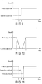
- FIG. 8 descriptions will be made of the temporal change of measured impedance and that of output.
- An upper figure (a) in FIG. 8 schematically shows values of measured impedance with respect to the passage of time, and a lower figure (b) in FIG. 8 schematically shows values of output of the output unit 140 with respect to the passage of time.
- the output switch is turned on at time t0.
- the output level is set to the first output level as shown in the lower figure (b) in FIG. 8 by the processing of step S106 described above. It is assumed that the first electrode 212 and the living tissue 900 are sufficiently distant from each other at this time. Accordingly, the measured impedance Zmeas acquired by the above processing of step S109 is showing a high value. This value is stored as the maximum value Zmax of impedance.
- the measured impedance Zmeas gradually falls due to the first electrode 212 and the living tissue 900 gradually approaching each other, its accompanying electric discharge, etc.
- the measured impedance Zmeas at time t2 is lower than the impedance maximum value Zmax.
- the setting of the second threshold enables adjustment of sensitivity for the transition to the blanking period. That is, adopting a smaller second threshold increases the sensitivity and adopting a larger second threshold decreases the sensitivity.
- This second threshold may be set as appropriate.
- the measured impedance Zmeas falls further since the first electrode 212 and the living tissue 900 further approach each other.
- the blanking period for which the output is at the second output level is determined by the processing of step S115 and step S116 described above.
- the time at which the blanking period has passed is given as time t5.
- the output is changed to the first output level by the processing of step S106 described above.
- the first output level has been set. This is because treatments such as incision and hemostasis begin from the time t6, and the output level desired by a user is required to have been set at the latest by the time point that the first electrode 212 and the living tissue 900 make contact.
- the time t0 to time t1 represent a period where incision is not performed
- the time t6 and onward represent a period for performing treatment such as incision and hemostasis
- the period from the time t1 to time t6 is a transition period up to the first electrode 212 contacting the living tissue 900. It has been known that at some point during this transition period, the output value could instantaneously deviate from a target value to a large extent due to the unintentional occurrence of a large electric discharge between the first electrode 212 and the living tissue 900, or the like.
- This embodiment predicts a start of incision based on the impedance measurement and temporarily suppresses output for a certain time during the transition period immediately before the incision. With this temporal output suppression, the output value can be prevented from instantaneously deviating from a target value to a large extent.
- the second output level for the blanking period is not limited to this, but may take any value as long as it is smaller than the first output level before and after the blanking period and it does not largely deviate from the target value.
- the second output level may be a value smaller than the first output level and larger than zero. As such, the output during the blanking period would serve as long as it is at the second output level lower than the first output level, inclusive of zero.
- the power supply device 100 may gradually change the output from the first output level to the second output level as shown in FIG. 10 . Also, the power supply device 100 may gradually change the output from the second output level to the first output level. Generally, such devices involve large output levels, so a rapid change of output levels often generates electric noise. Accordingly, a noise reduction effect can be expected by changing the output levels gradually.
- the above embodiment has given an example where the output level is changed between the first output level and the second output level for the blanking period, but this is not a limitation.
- the blanking period may be divided into multiple portions as shown in FIG. 11 . That is, the power supply device 100 changes the output level from a first output level to a second output level when a predetermined condition is satisfied. Furthermore, the power supply device 100 changes the output level from the second output level to a third output level when another predetermined condition is satisfied. Also, the power supply device 100 changes the output level from the third output level to the first output level when still another predetermined condition is satisfied.
- the power supply device 100 may also change the output level in a stepwise manner with three or more stages. The power supply device 100 may gradually lower the output level or change it in other patterns, too.
- the power supply device 100 may set the output level prior to the blanking period to a third output level that gives an output sufficient to allow impedance measurement while being at a low output level.
- the power supply device 100 may, after the blanking period has passed, set the output level to a first output level which is an output level set by a user.
- the power supply device 100 may change the output level alternately at any number of times between a first output level and a second output level lower than the first output level.
- the second output level and a third output level equal to or lower than the first output level may be repeated for the sake of reduction of noise generation as above.
- Gradual changes of the output level in this manner can prevent the output value from instantaneously deviating significantly from a target value.
- a certain performance of the treatment such as incision and coagulation in the blanking period can be secured.
- the blanking period is not limited to the subject of determination at a predetermined time as in the embodiment described above.
- it may be configured so that the output level is changed to the first output level when the measured impedance falls below a predetermined value.
- the output level can be lowered to the second output level when the living tissue 900 and the first electrode 212 are within a predetermined distance range, no matter how fast a user moves the first electrode 212.
- the above embodiment has given an example where a distance between the living tissue 900 and the first electrode 212 is estimated based on the impedance of a circuit.
- the distance between the living tissue 900 and the first electrode 212 may be derived from information other than the impedance of a circuit.
- the distance between the living tissue 900 and the first electrode 212 may be acquired based on current values or voltage values relating to the output.
- the distance between the living tissue 900 and the first electrode 212 may be acquired based on images obtained by, for example, an imaging device provided for observing a treatment subject site.
- the distance information acquisition unit 112 may include an image analyzing function.
- distance measurement methods which utilize, for example, light or sound waves may be used. In this instance, the distance information acquisition unit 112 acquires the distance between the living tissue 900 and the first electrode 212 using light or sound waves.
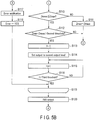
- the blanking period is initiated when the difference Zmax-Zmeas obtained by subtracting the measured impedance Zmeas from the impedance maximum value Zmax is larger than the predetermined second threshold. Nevertheless, if the blanking period is to be initiated upon satisfaction of the condition even once, a malfunction could occur due to the influence of noise, etc. Accordingly, the power supply device 100 may be configured so that the blanking period is initiated upon satisfaction of the condition a certain number of times. The processing in this instance will be described with reference to the flowcharts shown in FIG. 14A and FIG. 14B .
- step S201 to step S204 is the same as the processing in step S101 to step S104 in the above embodiment.
- the controller 110 determines at step S201 whether the output switch 250 is on or not. If it is not on, the processing proceeds to step S202. At step S202, it is determined whether or not to terminate the processing. If termination is determined, the processing ends. On the other hand, if termination is not determined, the processing returns to step S201. If it is determined at step S201 that the output switch is on, the processing proceeds to step S203.
- step S203 the controller 110 sets information about the presence of an error to No and sets a determination flag f to 0.
- Processing from step S204 to step S222 is repetitive processing.
- the condition for repeating is that the output switch 250 is on and there are no errors. When the output switch is turned off, or when there is an error, the processing comes out of this repetitive processing and proceeds to step S223.
- the controller 110 initializes variables stored in the storage 122.
- it sets the first counter i for measuring a blanking period to 0 and the second counter j for measuring a runtime error to 0, and additionally sets a third counter k for avoiding false detection to 0. It also sets the maximum value Zmax of impedance to a provisional value.
- step S206 to step S210 is the same as the processing in step S106 to step S110 in the above embodiment.
- the controller 110 at step S206 sets the level of output from the output unit 140 to the first output level.
- the controller 110 increases the value of the second counter j.
- the controller 110 determines whether or not the determination flag f is 1, or whether or not the second counter j is smaller than the predetermined first threshold. If the determination flag f is 1 or the second counter j is smaller than the first threshold, the processing proceeds to step S209.
- step S209 the controller 110 acquires the measured impedance Zmeas.
- step S210 the controller 110 determines whether or not the measured impedance Zmeas is equal to or smaller than the present maximum value Zmax. If the measured impedance Zmeas is not equal to or smaller than the maximum value Zmax, the processing proceeds to step S211.
- step S211 the controller 110 resets the value of the third counter k to 0. Subsequently at step S212, the controller 110 sets the maximum value Zmax to the measured impedance Zmeas. The processing then returns to step S207.
- step S210 if the measured impedance Zmeas is determined to be equal to or smaller than the maximum value Zmax, the processing proceeds to step S213.
- the controller 110 determines whether the difference Zmax-Zmeas obtained by subtracting the measured impedance Zmeas from the impedance maximum value Zmax is larger than the predetermined second threshold or not. If the difference Zmax-Zmeas is not larger than the second threshold, the processing returns to step S207. On the other hand, if the difference Zmax-Zmeas is larger than the second threshold, the processing proceeds to step S214.
- the controller 110 increases the value of the third counter k stored in the storage 122.
- step S215 the controller 110 determines whether the third counter k is larger than a predetermined fourth threshold or not. If the third counter k is not larger than the fourth threshold, the processing returns to step S207. On the other hand, if the third counter k is larger than the fourth threshold, the processing proceeds to step S216.
- step S213 when the number of times that the difference Zmax-Zmeas (which is obtained by subtracting the measured impedance Zmeas from the impedance maximum value Zmax) is determined to be larger than the second threshold exceeds the fourth threshold, the processing proceeds to step S216 for the first time.
- step S216 upon repeatedly determining that the difference Zmax-Zmeas is larger than the second threshold in this manner, unintended processing induced by noise, etc. that would change the output levels can be prevented.
- step S208 the determination flag f is not 1, and the second counter j is equal to or larger than the first threshold, the processing proceeds to step S220.
- step S220 the controller 110 performs error notification to indicate that the first electrode 212 has not been in contact with the living tissue 900 for a certain period despite the output switch being on.
- step S221 the controller 110 sets the information about the presence of an error to Yes. Then the processing proceeds to step S222. Since there is an error, the processing proceeds to step S223.
- step S223 the controller 110 halts the output of the output unit 140. The processing then returns to step S201.
- step S216 to step S223 is the same as the processing in step S113 to step S120 in the above embodiment.
- the controller 110 sets the determination flag f to 1 at step S216.
- step S217 the controller 110 sets the level of output from the output unit 140 to the second output level.
- step S218, the controller 110 increases the first counter i.
- step S219 the controller 110 determines whether the first counter i is larger than the predetermined third threshold or not. If the first counter i is not larger than the third threshold, the processing returns to step S218. That is, the processing at step S218 and step S219 is repeated until the first counter i exceeds the third threshold.
- step S219 if the first counter i is determined to be larger than the third threshold, the processing proceeds to step S222. That is, when the switch is on and there are no errors, the processing from step S204 is repeated.
- the sensitivity can be adjusted. While this example has adopted a determination criterion of whether or not the difference Zmax-Zmeas obtained by subtracting the measured impedance Zmeas from the impedance maximum value Zmax is larger than the predetermined second threshold, this is not a limitation. For example, whether an absolute value of the measured impedance Zmeas satisfies a predetermined condition or not may also be adopted as a determination criterion.
- the high frequency treatment instrument 220 has been described as an instrument with a function of performing high frequency treatment, but this is not a limitation.
- the high frequency treatment instrument 220 may also be an instrument that utilizes both high frequency energy and ultrasonic energy and treats a treatment subject by ultrasonic vibration as well.
- the high frequency treatment instrument 220 may also be a bipolar-type treatment instrument. In this case, two electrodes comprised by the treatment instrument would correspond to the first electrode 212 and the second electrode 214.
Landscapes
- Health & Medical Sciences (AREA)
- Engineering & Computer Science (AREA)
- Surgery (AREA)
- Life Sciences & Earth Sciences (AREA)
- Physics & Mathematics (AREA)
- Medical Informatics (AREA)
- Animal Behavior & Ethology (AREA)
- Nuclear Medicine, Radiotherapy & Molecular Imaging (AREA)
- Biomedical Technology (AREA)
- Heart & Thoracic Surgery (AREA)
- Plasma & Fusion (AREA)
- Molecular Biology (AREA)
- Otolaryngology (AREA)
- General Health & Medical Sciences (AREA)
- Public Health (AREA)
- Veterinary Medicine (AREA)
- General Engineering & Computer Science (AREA)
- Theoretical Computer Science (AREA)
- Computer Hardware Design (AREA)
- General Physics & Mathematics (AREA)
- Surgical Instruments (AREA)
Applications Claiming Priority (2)
| Application Number | Priority Date | Filing Date | Title |
|---|---|---|---|
| JP2015075408 | 2015-04-01 | ||
| PCT/JP2016/056965 WO2016158214A1 (fr) | 2015-04-01 | 2016-03-07 | Dispositif d'alimentation électrique pour instrument de traitement à haute fréquence, système de traitement à haute fréquence, et procédé de commande pour instrument de traitement à haute fréquence |
Publications (2)
| Publication Number | Publication Date |
|---|---|
| EP3207890A1 true EP3207890A1 (fr) | 2017-08-23 |
| EP3207890A4 EP3207890A4 (fr) | 2018-06-06 |
Family
ID=57007030
Family Applications (1)
| Application Number | Title | Priority Date | Filing Date |
|---|---|---|---|
| EP16772098.6A Withdrawn EP3207890A4 (fr) | 2015-04-01 | 2016-03-07 | Dispositif d'alimentation électrique pour instrument de traitement à haute fréquence, système de traitement à haute fréquence, et procédé de commande pour instrument de traitement à haute fréquence |
Country Status (5)
| Country | Link |
|---|---|
| US (1) | US20170245918A1 (fr) |
| EP (1) | EP3207890A4 (fr) |
| JP (1) | JP6058231B1 (fr) |
| CN (1) | CN107072710A (fr) |
| WO (1) | WO2016158214A1 (fr) |
Cited By (1)
| Publication number | Priority date | Publication date | Assignee | Title |
|---|---|---|---|---|
| WO2021119387A1 (fr) * | 2019-12-13 | 2021-06-17 | Conmed Corporation | Régulation de puissance pour un dispositif de scellement de récipient électrochirurgical |
Family Cites Families (14)
| Publication number | Priority date | Publication date | Assignee | Title |
|---|---|---|---|---|
| US4901720A (en) * | 1986-04-08 | 1990-02-20 | C. R. Bard, Inc. | Power control for beam-type electrosurgical unit |
| US6772012B2 (en) * | 1995-06-07 | 2004-08-03 | Arthrocare Corporation | Methods for electrosurgical treatment of spinal tissue |
| US6763836B2 (en) * | 1998-06-02 | 2004-07-20 | Arthrocare Corporation | Methods for electrosurgical tendon vascularization |
| JP2002253480A (ja) * | 2001-03-02 | 2002-09-10 | Olympus Optical Co Ltd | 医療処置補助装置 |
| JP5067992B2 (ja) * | 2001-07-26 | 2012-11-07 | 日立アロカメディカル株式会社 | 手術用装置 |
| US7655003B2 (en) * | 2005-06-22 | 2010-02-02 | Smith & Nephew, Inc. | Electrosurgical power control |
| US20070062547A1 (en) * | 2005-07-21 | 2007-03-22 | Carlo Pappone | Systems for and methods of tissue ablation |
| US10362959B2 (en) * | 2005-12-06 | 2019-07-30 | St. Jude Medical, Atrial Fibrillation Division, Inc. | System and method for assessing the proximity of an electrode to tissue in a body |
| US8827992B2 (en) * | 2010-03-26 | 2014-09-09 | Aesculap Ag | Impedance mediated control of power delivery for electrosurgery |
| CN102008350B (zh) * | 2010-11-17 | 2012-07-25 | 胡伟九 | 高频电外科手术仪 |
| US9687289B2 (en) * | 2012-01-04 | 2017-06-27 | Biosense Webster (Israel) Ltd. | Contact assessment based on phase measurement |
| MY179432A (en) * | 2013-02-07 | 2020-11-06 | Shanghai Golden Leaf Med Tec Co Ltd | Radio frequency ablation method, system and radio frequency ablation device thereof |
| JP6265630B2 (ja) * | 2013-06-13 | 2018-01-24 | オリンパス株式会社 | 内視鏡装置及び内視鏡装置の作動方法 |
| CN103519886A (zh) * | 2013-10-25 | 2014-01-22 | 胡峰 | 胆囊息肉高频电凝切除器 |
-
2016
- 2016-03-07 EP EP16772098.6A patent/EP3207890A4/fr not_active Withdrawn
- 2016-03-07 JP JP2016548338A patent/JP6058231B1/ja active Active
- 2016-03-07 WO PCT/JP2016/056965 patent/WO2016158214A1/fr not_active Ceased
- 2016-03-07 CN CN201680003242.3A patent/CN107072710A/zh active Pending
-
2017
- 2017-05-15 US US15/595,217 patent/US20170245918A1/en not_active Abandoned
Cited By (1)
| Publication number | Priority date | Publication date | Assignee | Title |
|---|---|---|---|---|
| WO2021119387A1 (fr) * | 2019-12-13 | 2021-06-17 | Conmed Corporation | Régulation de puissance pour un dispositif de scellement de récipient électrochirurgical |
Also Published As
| Publication number | Publication date |
|---|---|
| CN107072710A (zh) | 2017-08-18 |
| US20170245918A1 (en) | 2017-08-31 |
| JPWO2016158214A1 (ja) | 2017-04-27 |
| JP6058231B1 (ja) | 2017-01-11 |
| EP3207890A4 (fr) | 2018-06-06 |
| WO2016158214A1 (fr) | 2016-10-06 |
Similar Documents
| Publication | Publication Date | Title |
|---|---|---|
| US11701164B2 (en) | Energy treatment system and output control method thereof | |
| JP6033511B1 (ja) | 高周波処置具のための電源装置、高周波処置システム、及び電源装置の作動方法 | |
| US20250204973A1 (en) | Systems and methods for controlling arcing | |
| EP3207891A1 (fr) | Dispositif source d'énergie pour instrument de traitement haute fréquence, système de traitement haute fréquence, et procédé de commande pour un système de traitement haute fréquence | |
| EP3329872B1 (fr) | Dispositif d'alimentation en courant et système de traitement haute fréquence | |
| US20190142489A1 (en) | Energy treatment system and control method thereof | |
| EP3229717B1 (fr) | Générateur électrochirurgical, dispositif de commande et son procédé | |
| JP6258247B2 (ja) | 高周波交流による組織融合または組織凝固のための装置 | |
| CN109862836A (zh) | 能量处置系统 | |
| JP5681142B2 (ja) | 組織抵抗に依存して電圧を制御する電気的作用によって組織を溶解又は凝固させる方法及び装置 | |
| EP3207890A1 (fr) | Dispositif d'alimentation électrique pour instrument de traitement à haute fréquence, système de traitement à haute fréquence, et procédé de commande pour instrument de traitement à haute fréquence | |
| EP3272302B1 (fr) | Dispositif d'alimentation en énergie et système de traitement à haute fréquence | |
| US20200121380A1 (en) | Treatment system | |
| JP6095880B1 (ja) | 高周波処置具のための電源装置及びそれを備える処置システム | |
| CN105592813B (zh) | 高频外科手术装置及其操作方法 | |
| JP6253851B1 (ja) | 高周波処置具のための電源装置、高周波処置システム、及び高周波処置具の制御方法 | |
| US20190038339A1 (en) | Power Supply Device for High-Frequency Treatment Tool, High-Frequency Treatment System, and Method of Controlling High-Frequency Treatment Tool | |
| JP2024160955A (ja) | 電気外科システムおよび電気外科システムを操作するための方法 |
Legal Events
| Date | Code | Title | Description |
|---|---|---|---|
| STAA | Information on the status of an ep patent application or granted ep patent |
Free format text: STATUS: THE INTERNATIONAL PUBLICATION HAS BEEN MADE |
|
| PUAI | Public reference made under article 153(3) epc to a published international application that has entered the european phase |
Free format text: ORIGINAL CODE: 0009012 |
|
| STAA | Information on the status of an ep patent application or granted ep patent |
Free format text: STATUS: REQUEST FOR EXAMINATION WAS MADE |
|
| 17P | Request for examination filed |
Effective date: 20170518 |
|
| AK | Designated contracting states |
Kind code of ref document: A1 Designated state(s): AL AT BE BG CH CY CZ DE DK EE ES FI FR GB GR HR HU IE IS IT LI LT LU LV MC MK MT NL NO PL PT RO RS SE SI SK SM TR |
|
| AX | Request for extension of the european patent |
Extension state: BA ME |
|
| A4 | Supplementary search report drawn up and despatched |
Effective date: 20180507 |
|
| RIC1 | Information provided on ipc code assigned before grant |
Ipc: A61B 18/14 20060101ALN20180430BHEP Ipc: A61B 18/00 20060101ALN20180430BHEP Ipc: A61B 18/12 20060101AFI20180430BHEP |
|
| DAV | Request for validation of the european patent (deleted) | ||
| DAX | Request for extension of the european patent (deleted) | ||
| STAA | Information on the status of an ep patent application or granted ep patent |
Free format text: STATUS: THE APPLICATION IS DEEMED TO BE WITHDRAWN |
|
| 18D | Application deemed to be withdrawn |
Effective date: 20181205 |