EP3207956A2 - Procédé de fabrication d'une conduite d'électrodes ou d'un cathéter et semi-produit correspondant - Google Patents
Procédé de fabrication d'une conduite d'électrodes ou d'un cathéter et semi-produit correspondant Download PDFInfo
- Publication number
- EP3207956A2 EP3207956A2 EP17151704.8A EP17151704A EP3207956A2 EP 3207956 A2 EP3207956 A2 EP 3207956A2 EP 17151704 A EP17151704 A EP 17151704A EP 3207956 A2 EP3207956 A2 EP 3207956A2
- Authority
- EP
- European Patent Office
- Prior art keywords
- region
- semifinished product
- connection point
- jacket
- cable
- Prior art date
- Legal status (The legal status is an assumption and is not a legal conclusion. Google has not performed a legal analysis and makes no representation as to the accuracy of the status listed.)
- Granted
Links
Images

Classifications
-
- H—ELECTRICITY
- H01—ELECTRIC ELEMENTS
- H01B—CABLES; CONDUCTORS; INSULATORS; SELECTION OF MATERIALS FOR THEIR CONDUCTIVE, INSULATING OR DIELECTRIC PROPERTIES
- H01B7/00—Insulated conductors or cables characterised by their form
- H01B7/02—Disposition of insulation
-
- A—HUMAN NECESSITIES
- A61—MEDICAL OR VETERINARY SCIENCE; HYGIENE
- A61N—ELECTROTHERAPY; MAGNETOTHERAPY; RADIATION THERAPY; ULTRASOUND THERAPY
- A61N1/00—Electrotherapy; Circuits therefor
- A61N1/02—Details
-
- A—HUMAN NECESSITIES
- A61—MEDICAL OR VETERINARY SCIENCE; HYGIENE
- A61B—DIAGNOSIS; SURGERY; IDENTIFICATION
- A61B5/00—Measuring for diagnostic purposes; Identification of persons
- A61B5/68—Arrangements of detecting, measuring or recording means, e.g. sensors, in relation to patient
- A61B5/6846—Arrangements of detecting, measuring or recording means, e.g. sensors, in relation to patient specially adapted to be brought in contact with an internal body part, i.e. invasive
- A61B5/6847—Arrangements of detecting, measuring or recording means, e.g. sensors, in relation to patient specially adapted to be brought in contact with an internal body part, i.e. invasive mounted on an invasive device
- A61B5/6852—Catheters
-
- H—ELECTRICITY
- H01—ELECTRIC ELEMENTS
- H01R—ELECTRICALLY-CONDUCTIVE CONNECTIONS; STRUCTURAL ASSOCIATIONS OF A PLURALITY OF MUTUALLY-INSULATED ELECTRICAL CONNECTING ELEMENTS; COUPLING DEVICES; CURRENT COLLECTORS
- H01R43/00—Apparatus or processes specially adapted for manufacturing, assembling, maintaining, or repairing of line connectors or current collectors or for joining electric conductors
- H01R43/005—Apparatus or processes specially adapted for manufacturing, assembling, maintaining, or repairing of line connectors or current collectors or for joining electric conductors for making dustproof, splashproof, drip-proof, waterproof, or flameproof connection, coupling, or casing
-
- H—ELECTRICITY
- H01—ELECTRIC ELEMENTS
- H01R—ELECTRICALLY-CONDUCTIVE CONNECTIONS; STRUCTURAL ASSOCIATIONS OF A PLURALITY OF MUTUALLY-INSULATED ELECTRICAL CONNECTING ELEMENTS; COUPLING DEVICES; CURRENT COLLECTORS
- H01R43/00—Apparatus or processes specially adapted for manufacturing, assembling, maintaining, or repairing of line connectors or current collectors or for joining electric conductors
- H01R43/20—Apparatus or processes specially adapted for manufacturing, assembling, maintaining, or repairing of line connectors or current collectors or for joining electric conductors for assembling or disassembling contact members with insulating base, case or sleeve
- H01R43/24—Assembling by moulding on contact members
-
- H—ELECTRICITY
- H02—GENERATION; CONVERSION OR DISTRIBUTION OF ELECTRIC POWER
- H02G—INSTALLATION OF ELECTRIC CABLES OR LINES, OR OF COMBINED OPTICAL AND ELECTRIC CABLES OR LINES
- H02G1/00—Methods or apparatus specially adapted for installing, maintaining, repairing or dismantling electric cables or lines
- H02G1/14—Methods or apparatus specially adapted for installing, maintaining, repairing or dismantling electric cables or lines for joining or terminating cables
-
- H—ELECTRICITY
- H02—GENERATION; CONVERSION OR DISTRIBUTION OF ELECTRIC POWER
- H02G—INSTALLATION OF ELECTRIC CABLES OR LINES, OR OF COMBINED OPTICAL AND ELECTRIC CABLES OR LINES
- H02G15/00—Cable fittings
- H02G15/02—Cable terminations
-
- A—HUMAN NECESSITIES
- A61—MEDICAL OR VETERINARY SCIENCE; HYGIENE
- A61B—DIAGNOSIS; SURGERY; IDENTIFICATION
- A61B2562/00—Details of sensors; Constructional details of sensor housings or probes; Accessories for sensors
- A61B2562/02—Details of sensors specially adapted for in-vivo measurements
- A61B2562/0209—Special features of electrodes classified in A61B5/24, A61B5/25, A61B5/283, A61B5/291, A61B5/296, A61B5/053
-
- A—HUMAN NECESSITIES
- A61—MEDICAL OR VETERINARY SCIENCE; HYGIENE
- A61B—DIAGNOSIS; SURGERY; IDENTIFICATION
- A61B2562/00—Details of sensors; Constructional details of sensor housings or probes; Accessories for sensors
- A61B2562/12—Manufacturing methods specially adapted for producing sensors for in-vivo measurements
- A61B2562/125—Manufacturing methods specially adapted for producing sensors for in-vivo measurements characterised by the manufacture of electrodes
-
- A—HUMAN NECESSITIES
- A61—MEDICAL OR VETERINARY SCIENCE; HYGIENE
- A61B—DIAGNOSIS; SURGERY; IDENTIFICATION
- A61B2562/00—Details of sensors; Constructional details of sensor housings or probes; Accessories for sensors
- A61B2562/22—Arrangements of medical sensors with cables or leads; Connectors or couplings specifically adapted for medical sensors
- A61B2562/221—Arrangements of sensors with cables or leads, e.g. cable harnesses
- A61B2562/222—Electrical cables or leads therefor, e.g. coaxial cables or ribbon cables
-
- A—HUMAN NECESSITIES
- A61—MEDICAL OR VETERINARY SCIENCE; HYGIENE
- A61B—DIAGNOSIS; SURGERY; IDENTIFICATION
- A61B2562/00—Details of sensors; Constructional details of sensor housings or probes; Accessories for sensors
- A61B2562/22—Arrangements of medical sensors with cables or leads; Connectors or couplings specifically adapted for medical sensors
- A61B2562/225—Connectors or couplings
-
- A—HUMAN NECESSITIES
- A61—MEDICAL OR VETERINARY SCIENCE; HYGIENE
- A61M—DEVICES FOR INTRODUCING MEDIA INTO, OR ONTO, THE BODY; DEVICES FOR TRANSDUCING BODY MEDIA OR FOR TAKING MEDIA FROM THE BODY; DEVICES FOR PRODUCING OR ENDING SLEEP OR STUPOR
- A61M25/00—Catheters; Hollow probes
- A61M25/0009—Making of catheters or other medical or surgical tubes
-
- A—HUMAN NECESSITIES
- A61—MEDICAL OR VETERINARY SCIENCE; HYGIENE
- A61N—ELECTROTHERAPY; MAGNETOTHERAPY; RADIATION THERAPY; ULTRASOUND THERAPY
- A61N1/00—Electrotherapy; Circuits therefor
- A61N1/02—Details
- A61N1/04—Electrodes
- A61N1/05—Electrodes for implantation or insertion into the body, e.g. heart electrode
-
- H—ELECTRICITY
- H01—ELECTRIC ELEMENTS
- H01R—ELECTRICALLY-CONDUCTIVE CONNECTIONS; STRUCTURAL ASSOCIATIONS OF A PLURALITY OF MUTUALLY-INSULATED ELECTRICAL CONNECTING ELEMENTS; COUPLING DEVICES; CURRENT COLLECTORS
- H01R2201/00—Connectors or connections adapted for particular applications
- H01R2201/12—Connectors or connections adapted for particular applications for medicine and surgery
Definitions
- the invention relates to a method for producing a medical electrode lead or a catheter and to a corresponding semifinished product.
- the electrical connection technology is an elementary component for the production of electrical assemblies and ultimately electrical equipment and ensures the connection of the components with each other and for the connection technology to the outside world. Likewise, a number of electrical contact points are sometimes found within components.
- solder joints and solderless joints Another subdivision can be done in solder joints and solderless joints. For medical products intended for intracorporeal use, preferably solderless connections should be made.
- the solubility or conditional solubility is provided for larger and more expensive equipment.
- the bonding method chosen tends to be based on the least expensive manufacturing process for the producer, and hardly takes into account repairability.
- the latter product range includes catheters and electrodes for medical applications, in which in particular flexible materials are used.
- these products typically include cable-shaped components in which one or more conductors are embedded in a flexible insulator.
- the production of such flexible conductor sections for catheters and electrodes is currently subject to a length restriction due to production. Cable section lengths from about 60 cm and more must be created for this reason by putting together several sections.
- the electrical connection of the individual sections must be durable and reliable and should only use biocompatible materials. There is therefore a continuing need for a low cost and medical grade connection technology.
- the invention is based on the finding that it is possible to produce a reliable electrical connection of the individual components of a flexible medical electrode or a flexible catheter with the aid of specifically shaped connection points and without the addition of further materials for establishing the connection.
- the necessary semi-finished products have a cable inside which one or more electrical conductors for signal transmission or power line are located. At least at one end of the cable is the already mentioned connection point.
- the second cable end may also have a connection point, so that the semifinished product is a center piece in the manufacture of an electrode and a catheter of at least three individual parts. If the semifinished product is an end piece, the second end of the cable carries, for example, elements which serve to perceive the later function of the electrode or of the catheter.
- connection point provided at the cable end of the semifinished product serves to create a permanent and non-detachable electrical connection between two semi-finished products which have complementary connection points.
- part of the surface of the conductor is freely accessible for this purpose.
- the electrical contact to a second semifinished product with a complementary connection point is to be created via this freely accessible area.
- the electrical conductor is only partially exposed over the entire length of the connection point, that is, at least one underside of the three-dimensional conductor structure is always covered by a portion of the jacket of the electrically insulating thermoplastic material.
- a contour and dimensioning of the joints of two complementary semi-finished products should therefore be created so that always the mechanical integrity of the respective junction is maintained.
- connection point shows a recess extending in the longitudinal direction of the cable.
- the shape of this recess corresponds at least substantially to the shape of a connection point of a second semifinished product, so that the two connection points are stacked on each other (almost) without gaps surrounding the electrical conductors to be contacted.
- the material in the region of the joint and in the other portions of the cable may or may not necessarily be the same. The same applies to the material choice of the jacket in the area of the connection point and the other areas of the cable. But is particularly preferred at least the material of the jacket in the region of the joint and in the other sections of the cable identical.
- the individual cables of the semifinished products therefore have specially shaped ends which match one another in the key-lock principle and, if appropriate, can be laminated to one another by suitable shaping, so that an electrically sound and durable connection is produced.
- the necessary connection of individually manufactured cables can be made cheaper and more reliable as a result.
- cable harnesses of individually produced semi-finished products for the production of electrodes or catheters can be permanently connected by an automatable thermal joining process (optionally with the use of pressure).
- a plurality of electrically insulated from each other insulated lines within the cable can be reliably contacted without noticeable increase in electrical resistance.
- the resulting joint is hermetically sealed and can not be seen without optical aids.
- Catheters and electrodes for medical applications which are made of flexible printed circuit boards, can thus be extended by means of a positive connection.
- the method according to the invention also differs from conventional joining methods in that no additional materials (for example soldering material or conductive adhesives) are used.
- the electrical contact is formed by contact between the metal structures in the region of the connection points. The stability of the electrical connection results from the tightly enclosing plastic body, which permanently maintains the contact of the metal structures.
- step c) of thermal fusion comprises heating the material from a temperature in the range of 80 ° C to 450 ° C for a duration in the range of 1 second to 30 minutes.
- the connection points can also be acted upon in step c) or immediately after step c) with a pressure in the range of 1 to 40 bar.
- the electrical connection can be created very reliable.
- the thermal fusion of the material can in particular by Ultrasound treatment done or at least supported.
- the connection between the contact surfaces of the two conductors is supported before, after or during the fusion by an additional ultrasound treatment.
- the conductor at least in the region of the contact surface of the connection point, consists of a metal layer applied to the jacket.
- the metal layer may be formed of (i) at least one noble metal or at least one noble metal alloy or (ii) of a copper line covered with at least one noble metal or at least one noble metal alloy.
- gold, silver, palladium or their alloys are suitable.
- the noble metals on the free surface of the conductor prevent the formation of an oxide layer.
- the metal layer may have a width in the range of 5 to 100 microns.
- a thickness of the metal layer is preferably in the range of 0.1 to 25 ⁇ m.
- the contact area is 1 ⁇ m 2 to 1 mm 2 .
- the metal layer preferably has an increase in the region of the contact surface.
- a partially applied particle or bond ball
- the electrical contact can be created very reliable and with little waste. This particle is deformed during thermal fusion and thus bridges any gap between the two conductors to be joined. By using the particle, the contact surface can be minimized.
- the thermoplastic material of the jacket is preferably a plastic, in particular a thermoplastic with a processing temperature of less than 350 ° C, preferably less than 250 ° C.
- the plastic is selected from the group comprising polyethylene (PE), polypropylene (PP), polycarbonate (PC), polyvinyl chloride (PVC), acrylonitrile-butadiene-styrene copolymer (ABS), polyethylene terephthalate (PET), liquid crystal polymers, polyurethane, polyetheretherketone (PEEK) and copolymers of the polyurethane.
- the plastic is particularly preferably selected from the group comprising liquid crystal polymers, polyurethane and copolymers of the polyurethane.
- the materials mentioned are distinguished by a particularly good process capability for the bonding method according to the invention. Furthermore, the joints of the semi-finished products can be produced particularly easily using these materials. For example, a metal coating of said plastics for the production of electrical conductors is readily possible.
- connection points must be designed so that their mechanical integrity is preserved in the singulated semifinished product and at the same time the connection method according to the invention is supported. Consequently, the complementary joints of two semi-finished products must be coordinated.
- This can be done in a particularly reliable and simple manner according to a first embodiment, in which the contours of the recess and the jacket in the region of the junction result in a cylinder enclosing the conductor, and the recess has the shape of a circle whose center angle .alpha Range of 90 ° to 270 °, in particular 135 ° to 225 °.
- the volume of the recess may be limited to the chord, except for the area of the contact surface. The segment height of the circle segment then results accordingly.
- the contours of the recess and the jacket in the region of the junction together form a cuboid enclosing the conductor, and a volume of the recess in the range of 75% to 125% of Volume of the shell in the region of the junction is.
- the cuboid of the shell may in particular have a thickness in the range of 10 to 500 ⁇ m.
- a contour of the recess is not congruent with a contour of the remaining part of the jacket in the region of the connection point.
- the matching connection points of two semi-finished products are not designed to be completely identical. In this way it can be achieved that semi-finished products can not be combined with each other, but only a suitable connection in the shaping is possible.
- the center point angle of the two complementary semi-finished products can be set to differ from 180 °. It is also conceivable to predetermine the volume of the recess not equal to the volume of the shell in the region of the connection point in the cuboid connection point described above.
- the contour of the recess with respect to an individualization of the connection point can be varied as desired.
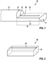
- FIG. 1 shows in a highly schematic manner a portion of a semifinished product 10, which serves for the production of a flexible electrode or a flexible catheter with medical application.
- the semifinished product 10 includes a cable 12 having a specially designed cable end 14.
- an electrical conductor 16 which is surrounded by a jacket 18 of an electrically insulating and thermoplastic material, such as a liquid crystal polymer or polyurethane.
- the cable 12 may also have a further sheath, if this is indicated for the particular application.
- the cable end 14 is part of the cable 12, that is, for the connection point 20 to be described in more detail, the same jacket material is used.
- the joint 20 is characterized in that parts of the shell 18 have been removed. Accordingly, the indicated by the dashed line recess 22, in the embodiment shown here, the jacket 18 takes in the region of the junction 20, the shape of a half-cylinder 24 a.
- the center angle ⁇ can also be specified differently from 180 °, so that a contour of the recess 22 and the jacket 18 in the region of the connection point 20 is no longer identical.
- a metal layer 26 is applied on the half-cylinder 24 of the jacket 18 in the region of the connection point 20 .
- a metal layer 26 is applied on the half-cylinder 24 of the jacket 18 in the region of the connection point 20.
- a metal layer 26 is applied on the half-cylinder 24 of the jacket 18 in the region of the connection point 20 .
- a metal layer 26 is applied on the half-cylinder 24 of the jacket 18 in the region of the connection point 20 a metal layer 26 is applied.
- such a structure can be produced by metal deposition of gold or palladium.
- a copper layer be applied, whose surface is in turn refined with gold or palladium.
- the materials mentioned have a particularly high conductivity.
- FIG. 2 is greatly simplified only to take a particular embodiment of the joint 20, wherein the still existing part of the jacket 18 assumes the shape of a cuboid.
- a metal layer 26 of gold is applied to this cuboid.
- the cuboid may consist of a thermoplastic liquid crystal polymer.
- connection points 20 each with lekssver secureddem conductor 16.
- connection points 20 each with lekssver secureddem conductor 16.
- connection points 20 each with lekssver secureddem conductor 16.
- it can also be connected to each other several parallel or any other different conductors. It is also conceivable that the metal structures meet only at individual points when lying on each other.
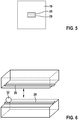
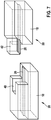
- a pressure of 1 to 40 bar is applied for producing the electrical connection and the tool 30 is briefly heated from the ambient temperature to 80 ° C. to 450 ° C. and cooled again (see FIG. 4 ).
- the contact surfaces of the two conductors 16 of the respective connection points 20 are opposite each other.
- the thermal treatment is maintained for 1 second to 30 minutes.
- the tool 30 is removed again.
- the tool 30 may have a shape that is molded into the plastic material during the heating process.
- the tool 30 may also be coated with Teflon or a ceramic to prevent adhesion of the thermoplastic to the tool 30. After the compression results in a homogeneous plastic body in which the metal layers 26 are embedded in each other lying (see FIG. 5 ).
- a gold particle 32 can be applied (see FIG. 6 ).
- the particle can lie in a small opening in the plastic and is deformed during compression.
- FIG. 7 is a further embodiment of the joint 20 to take two complementary semi-finished products.
- the two connection points 20 matched to each other matched structures. So that forms on the left side of the FIG. 7 illustrated connection point 20 from a niche 40, to which the connection point 20 shown on the right has a corresponding nose 42.
- the dimensions carry for example 5 to 100 microns width of the metal structures, 0.1 to 25 microns thickness of the metal structures and about 1 micron 2 to 1 mm 2 size of the contact surface (overlap of opposite metal layers 26).
- the metal layers can be applied to the plastic material chemically, electrochemically (galvanically) or by vacuum processes. Furthermore, it is conceivable to laminate metal on the support and to structure with known methods.
Landscapes
- Health & Medical Sciences (AREA)
- Engineering & Computer Science (AREA)
- Life Sciences & Earth Sciences (AREA)
- Manufacturing & Machinery (AREA)
- Veterinary Medicine (AREA)
- Biomedical Technology (AREA)
- Animal Behavior & Ethology (AREA)
- General Health & Medical Sciences (AREA)
- Public Health (AREA)
- Biophysics (AREA)
- Nuclear Medicine, Radiotherapy & Molecular Imaging (AREA)
- Physics & Mathematics (AREA)
- Radiology & Medical Imaging (AREA)
- Pathology (AREA)
- Heart & Thoracic Surgery (AREA)
- Medical Informatics (AREA)
- Molecular Biology (AREA)
- Surgery (AREA)
- Surgical Instruments (AREA)
- Electrotherapy Devices (AREA)
- Media Introduction/Drainage Providing Device (AREA)
Priority Applications (1)
| Application Number | Priority Date | Filing Date | Title |
|---|---|---|---|
| EP18192404.4A EP3434317A1 (fr) | 2016-01-29 | 2017-01-17 | Produit semi-fini pour la fabrication d'une conduite d'électrode ou d'un cathéter |
Applications Claiming Priority (1)
| Application Number | Priority Date | Filing Date | Title |
|---|---|---|---|
| DE102016101619.5A DE102016101619A1 (de) | 2016-01-29 | 2016-01-29 | Verfahren zur Herstellung einer Elektrodenleitung oder eines Katheters und dazugehöriges Halbzeug |
Related Child Applications (1)
| Application Number | Title | Priority Date | Filing Date |
|---|---|---|---|
| EP18192404.4A Division EP3434317A1 (fr) | 2016-01-29 | 2017-01-17 | Produit semi-fini pour la fabrication d'une conduite d'électrode ou d'un cathéter |
Publications (3)
| Publication Number | Publication Date |
|---|---|
| EP3207956A2 true EP3207956A2 (fr) | 2017-08-23 |
| EP3207956A3 EP3207956A3 (fr) | 2017-10-18 |
| EP3207956B1 EP3207956B1 (fr) | 2018-09-05 |
Family
ID=57914700
Family Applications (2)
| Application Number | Title | Priority Date | Filing Date |
|---|---|---|---|
| EP18192404.4A Withdrawn EP3434317A1 (fr) | 2016-01-29 | 2017-01-17 | Produit semi-fini pour la fabrication d'une conduite d'électrode ou d'un cathéter |
| EP17151704.8A Active EP3207956B1 (fr) | 2016-01-29 | 2017-01-17 | Procédé de fabrication d'une conduite d'électrodes ou d'un cathéter |
Family Applications Before (1)
| Application Number | Title | Priority Date | Filing Date |
|---|---|---|---|
| EP18192404.4A Withdrawn EP3434317A1 (fr) | 2016-01-29 | 2017-01-17 | Produit semi-fini pour la fabrication d'une conduite d'électrode ou d'un cathéter |
Country Status (3)
| Country | Link |
|---|---|
| US (1) | US10068681B2 (fr) |
| EP (2) | EP3434317A1 (fr) |
| DE (1) | DE102016101619A1 (fr) |
Families Citing this family (4)
| Publication number | Priority date | Publication date | Assignee | Title |
|---|---|---|---|---|
| DE102016101619A1 (de) | 2016-01-29 | 2017-08-03 | Biotronik Se & Co. Kg | Verfahren zur Herstellung einer Elektrodenleitung oder eines Katheters und dazugehöriges Halbzeug |
| US11217918B2 (en) * | 2016-07-28 | 2022-01-04 | 3M Innovative Properties Company | Electrical cable |
| DE102017117674A1 (de) * | 2017-08-03 | 2019-02-07 | Biotronik Se & Co. Kg | Elektrodenleitung oder Katheter, Verfahren zur Herstellung einer Elektrodenleitung oder eines Katheters und dazugehöriges Halbzeug |
| JP7279527B2 (ja) * | 2019-05-31 | 2023-05-23 | 株式会社オートネットワーク技術研究所 | 配線部材 |
Family Cites Families (16)
| Publication number | Priority date | Publication date | Assignee | Title |
|---|---|---|---|---|
| US3547718A (en) * | 1967-05-18 | 1970-12-15 | Rogers Corp | Method of making flat flexible electrical cables |
| US3522652A (en) * | 1967-09-15 | 1970-08-04 | Rogers Corp | Method of making an electrical circuit assembly |
| US4589584A (en) | 1985-01-31 | 1986-05-20 | International Business Machines Corporation | Electrical connection for polymeric conductive material |
| JPS63170875A (ja) * | 1987-01-09 | 1988-07-14 | 住友電気工業株式会社 | フラツト電線と金属端子のスポツト溶接方法 |
| US5097100A (en) * | 1991-01-25 | 1992-03-17 | Sundstrand Data Control, Inc. | Noble metal plated wire and terminal assembly, and method of making the same |
| US5354392A (en) | 1992-01-24 | 1994-10-11 | Matsushita Electric Industrial Co., Ltd. | Method for connecting a wiring arranged on a sheet with another wiring arranged on another sheet by ultrasonic waves |
| US6610930B1 (en) * | 1998-09-16 | 2003-08-26 | Kulicke & Soffa Investments, Inc. | Composite noble metal wire |
| US6686544B2 (en) * | 2001-04-25 | 2004-02-03 | Autonetworks Technologies, Ltd. | Wiring material and method for manufacturing the same |
| US7161226B2 (en) * | 2003-10-20 | 2007-01-09 | Industrial Technology Research Institute | Multi-layered complementary wire structure and manufacturing method thereof |
| US8250753B2 (en) | 2007-01-31 | 2012-08-28 | St. Jude Medical Ab | Method for manufacturing an active fixation electrode |
| US20090017197A1 (en) * | 2007-07-12 | 2009-01-15 | Sharp Laboratories Of America, Inc. | IrOx nanowire protein sensor |
| JP2014089944A (ja) * | 2012-10-01 | 2014-05-15 | Yazaki Corp | 同軸ケーブル |
| JP6020436B2 (ja) * | 2013-12-16 | 2016-11-02 | 住友電装株式会社 | 電線接続用の端子および該端子の電線接続構造 |
| CN204014250U (zh) | 2014-05-16 | 2014-12-10 | 奥特斯(中国)有限公司 | 用于生产电子元件的连接系统的半成品 |
| GB201418486D0 (en) * | 2014-10-17 | 2014-12-03 | Creo Medical Ltd | Cable for conveying radiofrequency and/or microwave frequency energy to an electrosurgical instrument |
| DE102016101619A1 (de) | 2016-01-29 | 2017-08-03 | Biotronik Se & Co. Kg | Verfahren zur Herstellung einer Elektrodenleitung oder eines Katheters und dazugehöriges Halbzeug |
-
2016
- 2016-01-29 DE DE102016101619.5A patent/DE102016101619A1/de not_active Withdrawn
-
2017
- 2017-01-05 US US15/399,098 patent/US10068681B2/en active Active
- 2017-01-17 EP EP18192404.4A patent/EP3434317A1/fr not_active Withdrawn
- 2017-01-17 EP EP17151704.8A patent/EP3207956B1/fr active Active
Also Published As
| Publication number | Publication date |
|---|---|
| EP3207956B1 (fr) | 2018-09-05 |
| US20170221602A1 (en) | 2017-08-03 |
| EP3434317A1 (fr) | 2019-01-30 |
| US10068681B2 (en) | 2018-09-04 |
| EP3207956A3 (fr) | 2017-10-18 |
| DE102016101619A1 (de) | 2017-08-03 |
Similar Documents
| Publication | Publication Date | Title |
|---|---|---|
| DE102014004433B4 (de) | Elektrische Leitungsvorrichtung, insbesondere für ein Kraftfahrzeug | |
| EP3631898B1 (fr) | Connecteur flexible | |
| DE102014118188A1 (de) | Zellkontaktierungssystem für eine elektrochemische Vorrichtung | |
| EP3207956B1 (fr) | Procédé de fabrication d'une conduite d'électrodes ou d'un cathéter | |
| DE102013220044A1 (de) | Zellkontaktierungssystem für eine elektrochemische Vorrichtung und Verfahren zum Herstellen eines Zellkontaktierungssystems | |
| DE102010043885A1 (de) | Akkupack mit einer Vielzahl von Zellen und Verfahren zur Herstellung eines Akkupacks | |
| DE102014114808A1 (de) | Elektronikmodul und Verfahren zur Herstellung eines Elektronikmoduls | |
| DE60124977T2 (de) | Elektrisches lötbares Verbindungselement mit Lötstelle | |
| EP2949004B1 (fr) | Procédé permettant l'établissement d'un raccordement électroconducteur entre une ligne électrique et un composant électroconducteur, et bloc fabriqué selon le procédé | |
| DE102017115879A1 (de) | Verfahren zur Herstellung eines leistungselektronischen Submodul mittels eines Schweißenverfahrens | |
| WO2006077157A1 (fr) | Dispositif pour produire un flux de courant electrique a travers des fibres de carbone | |
| EP0133883B1 (fr) | Connecteur pour soudage par ultrasons | |
| DE102018221635B3 (de) | Kontaktierungsverfahren und System | |
| EP3206258A1 (fr) | Système de fabrication d'un raccordement électrique, raccordement électrique et son procédé de fabrication | |
| DE102012214158A1 (de) | Kontaktelemente zur Kontaktierung von Flachleitern | |
| DE10255070B4 (de) | Anordnung zum Verbinden eines Erdungskabels mit einem flachen abgeschirmten Kabel und Verfahren zum Verbinden derselben | |
| DE102017117674A1 (de) | Elektrodenleitung oder Katheter, Verfahren zur Herstellung einer Elektrodenleitung oder eines Katheters und dazugehöriges Halbzeug | |
| EP4222817B1 (fr) | Raccordement électroconducteur destiné au contact électrique d'une électrode plane | |
| DE102021113511B3 (de) | Widerstandsschweißverfahren und Vorrichtung zum Widerstandsschweißen | |
| WO2007012514A1 (fr) | Connexion electroconductrice et procede de production de cette connexion | |
| DE102006025661B4 (de) | Kontaktklemme zum Anschließen eines Litzenleiters an einen relativ dünnen Anschlussstift | |
| AT515298B1 (de) | Verbindungselement zum Kontaktieren von zumindest einem Zellpol einer Batteriezelle | |
| DE3338757A1 (de) | Verfahren zum herstellen nicht loesbarer elektrischer verbindungen von draehten und/oder litzen untereinander sowie draehten und/oder litzen mit anschlusselementen durch ultraschallverschweissung, dabei verwendete ultraschallschweisseinrichtung sowie zugehoerige ultraschallverbinder | |
| EP3766310A1 (fr) | Procédé de fabrication d'une carte de circuit imprimé à l'aide d'un moule pour éléments conducteurs | |
| DE202013012897U1 (de) | Zellkontaktierungssystem für eine elektrochemische Vorrichtung |
Legal Events
| Date | Code | Title | Description |
|---|---|---|---|
| PUAI | Public reference made under article 153(3) epc to a published international application that has entered the european phase |
Free format text: ORIGINAL CODE: 0009012 |
|
| STAA | Information on the status of an ep patent application or granted ep patent |
Free format text: STATUS: THE APPLICATION HAS BEEN PUBLISHED |
|
| AK | Designated contracting states |
Kind code of ref document: A2 Designated state(s): AL AT BE BG CH CY CZ DE DK EE ES FI FR GB GR HR HU IE IS IT LI LT LU LV MC MK MT NL NO PL PT RO RS SE SI SK SM TR |
|
| AX | Request for extension of the european patent |
Extension state: BA ME |
|
| PUAL | Search report despatched |
Free format text: ORIGINAL CODE: 0009013 |
|
| AK | Designated contracting states |
Kind code of ref document: A3 Designated state(s): AL AT BE BG CH CY CZ DE DK EE ES FI FR GB GR HR HU IE IS IT LI LT LU LV MC MK MT NL NO PL PT RO RS SE SI SK SM TR |
|
| AX | Request for extension of the european patent |
Extension state: BA ME |
|
| RIC1 | Information provided on ipc code assigned before grant |
Ipc: A61N 1/02 20060101AFI20170908BHEP Ipc: H01R 43/00 20060101ALI20170908BHEP Ipc: A61M 25/00 20060101ALN20170908BHEP Ipc: H01B 13/00 20060101ALI20170908BHEP Ipc: A61N 1/05 20060101ALN20170908BHEP Ipc: B29C 65/78 20060101ALI20170908BHEP Ipc: H01B 7/04 20060101ALI20170908BHEP Ipc: H01R 43/24 20060101ALI20170908BHEP Ipc: A61B 5/00 20060101ALN20170908BHEP Ipc: B29C 65/00 20060101ALI20170908BHEP |
|
| STAA | Information on the status of an ep patent application or granted ep patent |
Free format text: STATUS: REQUEST FOR EXAMINATION WAS MADE |
|
| 17P | Request for examination filed |
Effective date: 20180404 |
|
| RBV | Designated contracting states (corrected) |
Designated state(s): AL AT BE BG CH CY CZ DE DK EE ES FI FR GB GR HR HU IE IS IT LI LT LU LV MC MK MT NL NO PL PT RO RS SE SI SK SM TR |
|
| GRAP | Despatch of communication of intention to grant a patent |
Free format text: ORIGINAL CODE: EPIDOSNIGR1 |
|
| STAA | Information on the status of an ep patent application or granted ep patent |
Free format text: STATUS: GRANT OF PATENT IS INTENDED |
|
| RIC1 | Information provided on ipc code assigned before grant |
Ipc: B29C 65/78 20060101ALI20180515BHEP Ipc: H01B 13/00 20060101ALI20180515BHEP Ipc: A61N 1/05 20060101ALN20180515BHEP Ipc: B29C 65/00 20060101ALI20180515BHEP Ipc: A61N 1/02 20060101AFI20180515BHEP Ipc: H01R 43/24 20060101ALI20180515BHEP Ipc: H01B 7/04 20060101ALI20180515BHEP Ipc: A61M 25/00 20060101ALN20180515BHEP Ipc: A61B 5/00 20060101ALN20180515BHEP Ipc: H01R 43/00 20060101ALI20180515BHEP |
|
| INTG | Intention to grant announced |
Effective date: 20180606 |
|
| GRAS | Grant fee paid |
Free format text: ORIGINAL CODE: EPIDOSNIGR3 |
|
| GRAA | (expected) grant |
Free format text: ORIGINAL CODE: 0009210 |
|
| STAA | Information on the status of an ep patent application or granted ep patent |
Free format text: STATUS: THE PATENT HAS BEEN GRANTED |
|
| AK | Designated contracting states |
Kind code of ref document: B1 Designated state(s): AL AT BE BG CH CY CZ DE DK EE ES FI FR GB GR HR HU IE IS IT LI LT LU LV MC MK MT NL NO PL PT RO RS SE SI SK SM TR |
|
| REG | Reference to a national code |
Ref country code: GB Ref legal event code: FG4D Free format text: NOT ENGLISH |
|
| REG | Reference to a national code |
Ref country code: CH Ref legal event code: EP |
|
| REG | Reference to a national code |
Ref country code: AT Ref legal event code: REF Ref document number: 1037142 Country of ref document: AT Kind code of ref document: T Effective date: 20180915 |
|
| REG | Reference to a national code |
Ref country code: IE Ref legal event code: FG4D Free format text: LANGUAGE OF EP DOCUMENT: GERMAN |
|
| REG | Reference to a national code |
Ref country code: DE Ref legal event code: R096 Ref document number: 502017000149 Country of ref document: DE |
|
| REG | Reference to a national code |
Ref country code: NL Ref legal event code: MP Effective date: 20180905 |
|
| REG | Reference to a national code |
Ref country code: LT Ref legal event code: MG4D |
|
| PG25 | Lapsed in a contracting state [announced via postgrant information from national office to epo] |
Ref country code: NO Free format text: LAPSE BECAUSE OF FAILURE TO SUBMIT A TRANSLATION OF THE DESCRIPTION OR TO PAY THE FEE WITHIN THE PRESCRIBED TIME-LIMIT Effective date: 20181205 Ref country code: GR Free format text: LAPSE BECAUSE OF FAILURE TO SUBMIT A TRANSLATION OF THE DESCRIPTION OR TO PAY THE FEE WITHIN THE PRESCRIBED TIME-LIMIT Effective date: 20181206 Ref country code: FI Free format text: LAPSE BECAUSE OF FAILURE TO SUBMIT A TRANSLATION OF THE DESCRIPTION OR TO PAY THE FEE WITHIN THE PRESCRIBED TIME-LIMIT Effective date: 20180905 Ref country code: SE Free format text: LAPSE BECAUSE OF FAILURE TO SUBMIT A TRANSLATION OF THE DESCRIPTION OR TO PAY THE FEE WITHIN THE PRESCRIBED TIME-LIMIT Effective date: 20180905 Ref country code: BG Free format text: LAPSE BECAUSE OF FAILURE TO SUBMIT A TRANSLATION OF THE DESCRIPTION OR TO PAY THE FEE WITHIN THE PRESCRIBED TIME-LIMIT Effective date: 20181205 Ref country code: LT Free format text: LAPSE BECAUSE OF FAILURE TO SUBMIT A TRANSLATION OF THE DESCRIPTION OR TO PAY THE FEE WITHIN THE PRESCRIBED TIME-LIMIT Effective date: 20180905 Ref country code: RS Free format text: LAPSE BECAUSE OF FAILURE TO SUBMIT A TRANSLATION OF THE DESCRIPTION OR TO PAY THE FEE WITHIN THE PRESCRIBED TIME-LIMIT Effective date: 20180905 |
|
| PG25 | Lapsed in a contracting state [announced via postgrant information from national office to epo] |
Ref country code: HR Free format text: LAPSE BECAUSE OF FAILURE TO SUBMIT A TRANSLATION OF THE DESCRIPTION OR TO PAY THE FEE WITHIN THE PRESCRIBED TIME-LIMIT Effective date: 20180905 Ref country code: LV Free format text: LAPSE BECAUSE OF FAILURE TO SUBMIT A TRANSLATION OF THE DESCRIPTION OR TO PAY THE FEE WITHIN THE PRESCRIBED TIME-LIMIT Effective date: 20180905 Ref country code: AL Free format text: LAPSE BECAUSE OF FAILURE TO SUBMIT A TRANSLATION OF THE DESCRIPTION OR TO PAY THE FEE WITHIN THE PRESCRIBED TIME-LIMIT Effective date: 20180905 |
|
| PG25 | Lapsed in a contracting state [announced via postgrant information from national office to epo] |
Ref country code: EE Free format text: LAPSE BECAUSE OF FAILURE TO SUBMIT A TRANSLATION OF THE DESCRIPTION OR TO PAY THE FEE WITHIN THE PRESCRIBED TIME-LIMIT Effective date: 20180905 Ref country code: NL Free format text: LAPSE BECAUSE OF FAILURE TO SUBMIT A TRANSLATION OF THE DESCRIPTION OR TO PAY THE FEE WITHIN THE PRESCRIBED TIME-LIMIT Effective date: 20180905 Ref country code: IS Free format text: LAPSE BECAUSE OF FAILURE TO SUBMIT A TRANSLATION OF THE DESCRIPTION OR TO PAY THE FEE WITHIN THE PRESCRIBED TIME-LIMIT Effective date: 20190105 Ref country code: PL Free format text: LAPSE BECAUSE OF FAILURE TO SUBMIT A TRANSLATION OF THE DESCRIPTION OR TO PAY THE FEE WITHIN THE PRESCRIBED TIME-LIMIT Effective date: 20180905 Ref country code: CZ Free format text: LAPSE BECAUSE OF FAILURE TO SUBMIT A TRANSLATION OF THE DESCRIPTION OR TO PAY THE FEE WITHIN THE PRESCRIBED TIME-LIMIT Effective date: 20180905 Ref country code: IT Free format text: LAPSE BECAUSE OF FAILURE TO SUBMIT A TRANSLATION OF THE DESCRIPTION OR TO PAY THE FEE WITHIN THE PRESCRIBED TIME-LIMIT Effective date: 20180905 Ref country code: RO Free format text: LAPSE BECAUSE OF FAILURE TO SUBMIT A TRANSLATION OF THE DESCRIPTION OR TO PAY THE FEE WITHIN THE PRESCRIBED TIME-LIMIT Effective date: 20180905 |
|
| PG25 | Lapsed in a contracting state [announced via postgrant information from national office to epo] |
Ref country code: PT Free format text: LAPSE BECAUSE OF FAILURE TO SUBMIT A TRANSLATION OF THE DESCRIPTION OR TO PAY THE FEE WITHIN THE PRESCRIBED TIME-LIMIT Effective date: 20190105 Ref country code: SK Free format text: LAPSE BECAUSE OF FAILURE TO SUBMIT A TRANSLATION OF THE DESCRIPTION OR TO PAY THE FEE WITHIN THE PRESCRIBED TIME-LIMIT Effective date: 20180905 Ref country code: SM Free format text: LAPSE BECAUSE OF FAILURE TO SUBMIT A TRANSLATION OF THE DESCRIPTION OR TO PAY THE FEE WITHIN THE PRESCRIBED TIME-LIMIT Effective date: 20180905 |
|
| REG | Reference to a national code |
Ref country code: DE Ref legal event code: R097 Ref document number: 502017000149 Country of ref document: DE |
|
| PLBE | No opposition filed within time limit |
Free format text: ORIGINAL CODE: 0009261 |
|
| STAA | Information on the status of an ep patent application or granted ep patent |
Free format text: STATUS: NO OPPOSITION FILED WITHIN TIME LIMIT |
|
| PG25 | Lapsed in a contracting state [announced via postgrant information from national office to epo] |
Ref country code: ES Free format text: LAPSE BECAUSE OF FAILURE TO SUBMIT A TRANSLATION OF THE DESCRIPTION OR TO PAY THE FEE WITHIN THE PRESCRIBED TIME-LIMIT Effective date: 20180905 Ref country code: DK Free format text: LAPSE BECAUSE OF FAILURE TO SUBMIT A TRANSLATION OF THE DESCRIPTION OR TO PAY THE FEE WITHIN THE PRESCRIBED TIME-LIMIT Effective date: 20180905 |
|
| 26N | No opposition filed |
Effective date: 20190606 |
|
| PG25 | Lapsed in a contracting state [announced via postgrant information from national office to epo] |
Ref country code: SI Free format text: LAPSE BECAUSE OF FAILURE TO SUBMIT A TRANSLATION OF THE DESCRIPTION OR TO PAY THE FEE WITHIN THE PRESCRIBED TIME-LIMIT Effective date: 20180905 Ref country code: MC Free format text: LAPSE BECAUSE OF FAILURE TO SUBMIT A TRANSLATION OF THE DESCRIPTION OR TO PAY THE FEE WITHIN THE PRESCRIBED TIME-LIMIT Effective date: 20180905 |
|
| PG25 | Lapsed in a contracting state [announced via postgrant information from national office to epo] |
Ref country code: LU Free format text: LAPSE BECAUSE OF NON-PAYMENT OF DUE FEES Effective date: 20190117 |
|
| REG | Reference to a national code |
Ref country code: BE Ref legal event code: MM Effective date: 20190131 |
|
| PG25 | Lapsed in a contracting state [announced via postgrant information from national office to epo] |
Ref country code: FR Free format text: LAPSE BECAUSE OF NON-PAYMENT OF DUE FEES Effective date: 20190131 |
|
| PG25 | Lapsed in a contracting state [announced via postgrant information from national office to epo] |
Ref country code: BE Free format text: LAPSE BECAUSE OF NON-PAYMENT OF DUE FEES Effective date: 20190131 |
|
| PG25 | Lapsed in a contracting state [announced via postgrant information from national office to epo] |
Ref country code: TR Free format text: LAPSE BECAUSE OF FAILURE TO SUBMIT A TRANSLATION OF THE DESCRIPTION OR TO PAY THE FEE WITHIN THE PRESCRIBED TIME-LIMIT Effective date: 20180905 |
|
| PG25 | Lapsed in a contracting state [announced via postgrant information from national office to epo] |
Ref country code: MT Free format text: LAPSE BECAUSE OF FAILURE TO SUBMIT A TRANSLATION OF THE DESCRIPTION OR TO PAY THE FEE WITHIN THE PRESCRIBED TIME-LIMIT Effective date: 20180905 |
|
| PG25 | Lapsed in a contracting state [announced via postgrant information from national office to epo] |
Ref country code: CY Free format text: LAPSE BECAUSE OF FAILURE TO SUBMIT A TRANSLATION OF THE DESCRIPTION OR TO PAY THE FEE WITHIN THE PRESCRIBED TIME-LIMIT Effective date: 20180905 |
|
| PG25 | Lapsed in a contracting state [announced via postgrant information from national office to epo] |
Ref country code: HU Free format text: LAPSE BECAUSE OF FAILURE TO SUBMIT A TRANSLATION OF THE DESCRIPTION OR TO PAY THE FEE WITHIN THE PRESCRIBED TIME-LIMIT; INVALID AB INITIO Effective date: 20170117 |
|
| GBPC | Gb: european patent ceased through non-payment of renewal fee |
Effective date: 20210117 |
|
| PG25 | Lapsed in a contracting state [announced via postgrant information from national office to epo] |
Ref country code: GB Free format text: LAPSE BECAUSE OF NON-PAYMENT OF DUE FEES Effective date: 20210117 |
|
| PG25 | Lapsed in a contracting state [announced via postgrant information from national office to epo] |
Ref country code: MK Free format text: LAPSE BECAUSE OF FAILURE TO SUBMIT A TRANSLATION OF THE DESCRIPTION OR TO PAY THE FEE WITHIN THE PRESCRIBED TIME-LIMIT Effective date: 20180905 |
|
| REG | Reference to a national code |
Ref country code: AT Ref legal event code: MM01 Ref document number: 1037142 Country of ref document: AT Kind code of ref document: T Effective date: 20220117 |
|
| PG25 | Lapsed in a contracting state [announced via postgrant information from national office to epo] |
Ref country code: AT Free format text: LAPSE BECAUSE OF NON-PAYMENT OF DUE FEES Effective date: 20220117 |
|
| P01 | Opt-out of the competence of the unified patent court (upc) registered |
Effective date: 20230615 |
|
| REG | Reference to a national code |
Ref country code: DE Ref legal event code: R082 Ref document number: 502017000149 Country of ref document: DE Representative=s name: SCHULZ JUNGHANS PATENTANWAELTE PARTGMBB, DE Ref country code: DE Ref legal event code: R082 Ref document number: 502017000149 Country of ref document: DE Representative=s name: RANDOLL, SOEREN, DIPL.-CHEM. UNIV. DR. RER. NA, DE Ref country code: DE Ref legal event code: R081 Ref document number: 502017000149 Country of ref document: DE Owner name: DYCONEX AG, CH Free format text: FORMER OWNER: BIOTRONIK SE & CO. KG, 12359 BERLIN, DE |
|
| REG | Reference to a national code |
Ref country code: DE Ref legal event code: R082 Ref document number: 502017000149 Country of ref document: DE Representative=s name: SCHULZ JUNGHANS PATENTANWAELTE PARTGMBB, DE |
|
| REG | Reference to a national code |
Ref country code: CH Ref legal event code: R17 Free format text: ST27 STATUS EVENT CODE: U-0-0-R10-R17 (AS PROVIDED BY THE NATIONAL OFFICE) Effective date: 20260113 |
|
| REG | Reference to a national code |
Ref country code: CH Ref legal event code: U11 Free format text: ST27 STATUS EVENT CODE: U-0-0-U10-U11 (AS PROVIDED BY THE NATIONAL OFFICE) Effective date: 20260201 |
|
| PGFP | Annual fee paid to national office [announced via postgrant information from national office to epo] |
Ref country code: DE Payment date: 20260120 Year of fee payment: 10 Ref country code: IE Payment date: 20260121 Year of fee payment: 10 |
|
| PGFP | Annual fee paid to national office [announced via postgrant information from national office to epo] |
Ref country code: CH Payment date: 20260201 Year of fee payment: 10 |