EP3207965A1 - Beförderungsart - Google Patents
Beförderungsart Download PDFInfo
- Publication number
- EP3207965A1 EP3207965A1 EP14904150.1A EP14904150A EP3207965A1 EP 3207965 A1 EP3207965 A1 EP 3207965A1 EP 14904150 A EP14904150 A EP 14904150A EP 3207965 A1 EP3207965 A1 EP 3207965A1
- Authority
- EP
- European Patent Office
- Prior art keywords
- vehicle according
- differs
- vehicle
- wheel
- user
- Prior art date
- Legal status (The legal status is an assumption and is not a legal conclusion. Google has not performed a legal analysis and makes no representation as to the accuracy of the status listed.)
- Withdrawn
Links
Images

Classifications
-
- B—PERFORMING OPERATIONS; TRANSPORTING
- B62—LAND VEHICLES FOR TRAVELLING OTHERWISE THAN ON RAILS
- B62K—CYCLES; CYCLE FRAMES; CYCLE STEERING DEVICES; RIDER-OPERATED TERMINAL CONTROLS SPECIALLY ADAPTED FOR CYCLES; CYCLE AXLE SUSPENSIONS; CYCLE SIDECARS, FORECARS, OR THE LIKE
- B62K1/00—Unicycles
-
- A—HUMAN NECESSITIES
- A63—SPORTS; GAMES; AMUSEMENTS
- A63C—SKATES; SKIS; ROLLER SKATES; DESIGN OR LAYOUT OF COURTS, RINKS OR THE LIKE
- A63C17/00—Roller skates; Skate-boards
- A63C17/0006—Accessories
- A63C17/0013—Devices used in combination with the skate but not fixed to it, e.g. supporting frames, sail, sticks, auxiliary wheel aid
-
- A—HUMAN NECESSITIES
- A63—SPORTS; GAMES; AMUSEMENTS
- A63C—SKATES; SKIS; ROLLER SKATES; DESIGN OR LAYOUT OF COURTS, RINKS OR THE LIKE
- A63C17/00—Roller skates; Skate-boards
- A63C17/12—Roller skates; Skate-boards with driving mechanisms
-
- B—PERFORMING OPERATIONS; TRANSPORTING
- B60—VEHICLES IN GENERAL
- B60K—ARRANGEMENT OR MOUNTING OF PROPULSION UNITS OR OF TRANSMISSIONS IN VEHICLES; ARRANGEMENT OR MOUNTING OF PLURAL DIVERSE PRIME-MOVERS IN VEHICLES; AUXILIARY DRIVES FOR VEHICLES; INSTRUMENTATION OR DASHBOARDS FOR VEHICLES; ARRANGEMENTS IN CONNECTION WITH COOLING, AIR INTAKE, GAS EXHAUST OR FUEL SUPPLY OF PROPULSION UNITS IN VEHICLES
- B60K35/00—Instruments specially adapted for vehicles; Arrangement of instruments in or on vehicles
- B60K35/10—Input arrangements, i.e. from user to vehicle, associated with vehicle functions or specially adapted therefor
-
- B—PERFORMING OPERATIONS; TRANSPORTING
- B60—VEHICLES IN GENERAL
- B60K—ARRANGEMENT OR MOUNTING OF PROPULSION UNITS OR OF TRANSMISSIONS IN VEHICLES; ARRANGEMENT OR MOUNTING OF PLURAL DIVERSE PRIME-MOVERS IN VEHICLES; AUXILIARY DRIVES FOR VEHICLES; INSTRUMENTATION OR DASHBOARDS FOR VEHICLES; ARRANGEMENTS IN CONNECTION WITH COOLING, AIR INTAKE, GAS EXHAUST OR FUEL SUPPLY OF PROPULSION UNITS IN VEHICLES
- B60K35/00—Instruments specially adapted for vehicles; Arrangement of instruments in or on vehicles
- B60K35/60—Instruments characterised by their location or relative disposition in or on vehicles
-
- B—PERFORMING OPERATIONS; TRANSPORTING
- B60—VEHICLES IN GENERAL
- B60K—ARRANGEMENT OR MOUNTING OF PROPULSION UNITS OR OF TRANSMISSIONS IN VEHICLES; ARRANGEMENT OR MOUNTING OF PLURAL DIVERSE PRIME-MOVERS IN VEHICLES; AUXILIARY DRIVES FOR VEHICLES; INSTRUMENTATION OR DASHBOARDS FOR VEHICLES; ARRANGEMENTS IN CONNECTION WITH COOLING, AIR INTAKE, GAS EXHAUST OR FUEL SUPPLY OF PROPULSION UNITS IN VEHICLES
- B60K35/00—Instruments specially adapted for vehicles; Arrangement of instruments in or on vehicles
- B60K35/80—Arrangements for controlling instruments
-
- B—PERFORMING OPERATIONS; TRANSPORTING
- B60—VEHICLES IN GENERAL
- B60K—ARRANGEMENT OR MOUNTING OF PROPULSION UNITS OR OF TRANSMISSIONS IN VEHICLES; ARRANGEMENT OR MOUNTING OF PLURAL DIVERSE PRIME-MOVERS IN VEHICLES; AUXILIARY DRIVES FOR VEHICLES; INSTRUMENTATION OR DASHBOARDS FOR VEHICLES; ARRANGEMENTS IN CONNECTION WITH COOLING, AIR INTAKE, GAS EXHAUST OR FUEL SUPPLY OF PROPULSION UNITS IN VEHICLES
- B60K7/00—Disposition of motor in, or adjacent to, traction wheel
- B60K7/0007—Disposition of motor in, or adjacent to, traction wheel the motor being electric
-
- B—PERFORMING OPERATIONS; TRANSPORTING
- B60—VEHICLES IN GENERAL
- B60L—PROPULSION OF ELECTRICALLY-PROPELLED VEHICLES; SUPPLYING ELECTRIC POWER FOR AUXILIARY EQUIPMENT OF ELECTRICALLY-PROPELLED VEHICLES; ELECTRODYNAMIC BRAKE SYSTEMS FOR VEHICLES IN GENERAL; MAGNETIC SUSPENSION OR LEVITATION FOR VEHICLES; MONITORING OPERATING VARIABLES OF ELECTRICALLY-PROPELLED VEHICLES; ELECTRIC SAFETY DEVICES FOR ELECTRICALLY-PROPELLED VEHICLES
- B60L15/00—Methods, circuits, or devices for controlling the traction-motor speed of electrically-propelled vehicles
- B60L15/20—Methods, circuits, or devices for controlling the traction-motor speed of electrically-propelled vehicles for control of the vehicle or its driving motor to achieve a desired performance, e.g. speed, torque, programmed variation of speed
- B60L15/30—Methods, circuits, or devices for controlling the traction-motor speed of electrically-propelled vehicles for control of the vehicle or its driving motor to achieve a desired performance, e.g. speed, torque, programmed variation of speed with means to change over to human control
-
- B—PERFORMING OPERATIONS; TRANSPORTING
- B60—VEHICLES IN GENERAL
- B60L—PROPULSION OF ELECTRICALLY-PROPELLED VEHICLES; SUPPLYING ELECTRIC POWER FOR AUXILIARY EQUIPMENT OF ELECTRICALLY-PROPELLED VEHICLES; ELECTRODYNAMIC BRAKE SYSTEMS FOR VEHICLES IN GENERAL; MAGNETIC SUSPENSION OR LEVITATION FOR VEHICLES; MONITORING OPERATING VARIABLES OF ELECTRICALLY-PROPELLED VEHICLES; ELECTRIC SAFETY DEVICES FOR ELECTRICALLY-PROPELLED VEHICLES
- B60L50/00—Electric propulsion with power supplied within the vehicle
- B60L50/50—Electric propulsion with power supplied within the vehicle using propulsion power supplied by batteries or fuel cells
- B60L50/60—Electric propulsion with power supplied within the vehicle using propulsion power supplied by batteries or fuel cells using power supplied by batteries
- B60L50/66—Arrangements of batteries
-
- B—PERFORMING OPERATIONS; TRANSPORTING
- B60—VEHICLES IN GENERAL
- B60L—PROPULSION OF ELECTRICALLY-PROPELLED VEHICLES; SUPPLYING ELECTRIC POWER FOR AUXILIARY EQUIPMENT OF ELECTRICALLY-PROPELLED VEHICLES; ELECTRODYNAMIC BRAKE SYSTEMS FOR VEHICLES IN GENERAL; MAGNETIC SUSPENSION OR LEVITATION FOR VEHICLES; MONITORING OPERATING VARIABLES OF ELECTRICALLY-PROPELLED VEHICLES; ELECTRIC SAFETY DEVICES FOR ELECTRICALLY-PROPELLED VEHICLES
- B60L53/00—Methods of charging batteries, specially adapted for electric vehicles; Charging stations or on-board charging equipment therefor; Exchange of energy storage elements in electric vehicles
- B60L53/10—Methods of charging batteries, specially adapted for electric vehicles; Charging stations or on-board charging equipment therefor; Exchange of energy storage elements in electric vehicles characterised by the energy transfer between the charging station and the vehicle
- B60L53/14—Conductive energy transfer
- B60L53/16—Connectors, e.g. plugs or sockets, specially adapted for charging electric vehicles
-
- B—PERFORMING OPERATIONS; TRANSPORTING
- B60—VEHICLES IN GENERAL
- B60L—PROPULSION OF ELECTRICALLY-PROPELLED VEHICLES; SUPPLYING ELECTRIC POWER FOR AUXILIARY EQUIPMENT OF ELECTRICALLY-PROPELLED VEHICLES; ELECTRODYNAMIC BRAKE SYSTEMS FOR VEHICLES IN GENERAL; MAGNETIC SUSPENSION OR LEVITATION FOR VEHICLES; MONITORING OPERATING VARIABLES OF ELECTRICALLY-PROPELLED VEHICLES; ELECTRIC SAFETY DEVICES FOR ELECTRICALLY-PROPELLED VEHICLES
- B60L53/00—Methods of charging batteries, specially adapted for electric vehicles; Charging stations or on-board charging equipment therefor; Exchange of energy storage elements in electric vehicles
- B60L53/80—Exchanging energy storage elements, e.g. removable batteries
-
- B—PERFORMING OPERATIONS; TRANSPORTING
- B60—VEHICLES IN GENERAL
- B60L—PROPULSION OF ELECTRICALLY-PROPELLED VEHICLES; SUPPLYING ELECTRIC POWER FOR AUXILIARY EQUIPMENT OF ELECTRICALLY-PROPELLED VEHICLES; ELECTRODYNAMIC BRAKE SYSTEMS FOR VEHICLES IN GENERAL; MAGNETIC SUSPENSION OR LEVITATION FOR VEHICLES; MONITORING OPERATING VARIABLES OF ELECTRICALLY-PROPELLED VEHICLES; ELECTRIC SAFETY DEVICES FOR ELECTRICALLY-PROPELLED VEHICLES
- B60L7/00—Electrodynamic brake systems for vehicles in general
- B60L7/10—Dynamic electric regenerative braking
-
- B—PERFORMING OPERATIONS; TRANSPORTING
- B60—VEHICLES IN GENERAL
- B60T—VEHICLE BRAKE CONTROL SYSTEMS OR PARTS THEREOF; BRAKE CONTROL SYSTEMS OR PARTS THEREOF, IN GENERAL; ARRANGEMENT OF BRAKING ELEMENTS ON VEHICLES IN GENERAL; PORTABLE DEVICES FOR PREVENTING UNWANTED MOVEMENT OF VEHICLES; VEHICLE MODIFICATIONS TO FACILITATE COOLING OF BRAKES
- B60T7/00—Brake-action initiating means
- B60T7/02—Brake-action initiating means for personal initiation
- B60T7/08—Brake-action initiating means for personal initiation hand actuated
- B60T7/10—Disposition of hand control
- B60T7/102—Disposition of hand control by means of a tilting lever
-
- B—PERFORMING OPERATIONS; TRANSPORTING
- B62—LAND VEHICLES FOR TRAVELLING OTHERWISE THAN ON RAILS
- B62D—MOTOR VEHICLES; TRAILERS
- B62D51/00—Motor vehicles characterised by the driver not being seated
- B62D51/02—Motor vehicles characterised by the driver not being seated the driver standing in the vehicle
-
- B—PERFORMING OPERATIONS; TRANSPORTING
- B62—LAND VEHICLES FOR TRAVELLING OTHERWISE THAN ON RAILS
- B62K—CYCLES; CYCLE FRAMES; CYCLE STEERING DEVICES; RIDER-OPERATED TERMINAL CONTROLS SPECIALLY ADAPTED FOR CYCLES; CYCLE AXLE SUSPENSIONS; CYCLE SIDECARS, FORECARS, OR THE LIKE
- B62K11/00—Motorcycles, engine-assisted cycles or motor scooters with one or two wheels
-
- B—PERFORMING OPERATIONS; TRANSPORTING
- B62—LAND VEHICLES FOR TRAVELLING OTHERWISE THAN ON RAILS
- B62M—RIDER PROPULSION OF WHEELED VEHICLES OR SLEDGES; POWERED PROPULSION OF SLEDGES OR SINGLE-TRACK CYCLES; TRANSMISSIONS SPECIALLY ADAPTED FOR SUCH VEHICLES
- B62M6/00—Rider propulsion of wheeled vehicles with additional source of power, e.g. combustion engine or electric motor
- B62M6/40—Rider propelled cycles with auxiliary electric motor
- B62M6/45—Control or actuating devices therefor
-
- B—PERFORMING OPERATIONS; TRANSPORTING
- B62—LAND VEHICLES FOR TRAVELLING OTHERWISE THAN ON RAILS
- B62M—RIDER PROPULSION OF WHEELED VEHICLES OR SLEDGES; POWERED PROPULSION OF SLEDGES OR SINGLE-TRACK CYCLES; TRANSMISSIONS SPECIALLY ADAPTED FOR SUCH VEHICLES
- B62M6/00—Rider propulsion of wheeled vehicles with additional source of power, e.g. combustion engine or electric motor
- B62M6/80—Accessories, e.g. power sources; Arrangements thereof
- B62M6/90—Batteries
-
- B—PERFORMING OPERATIONS; TRANSPORTING
- B60—VEHICLES IN GENERAL
- B60K—ARRANGEMENT OR MOUNTING OF PROPULSION UNITS OR OF TRANSMISSIONS IN VEHICLES; ARRANGEMENT OR MOUNTING OF PLURAL DIVERSE PRIME-MOVERS IN VEHICLES; AUXILIARY DRIVES FOR VEHICLES; INSTRUMENTATION OR DASHBOARDS FOR VEHICLES; ARRANGEMENTS IN CONNECTION WITH COOLING, AIR INTAKE, GAS EXHAUST OR FUEL SUPPLY OF PROPULSION UNITS IN VEHICLES
- B60K2360/00—Indexing scheme associated with groups B60K35/00 or B60K37/00 relating to details of instruments or dashboards
- B60K2360/77—Instrument locations other than the dashboard
- B60K2360/782—Instrument locations other than the dashboard on the steering wheel
-
- B—PERFORMING OPERATIONS; TRANSPORTING
- B60—VEHICLES IN GENERAL
- B60L—PROPULSION OF ELECTRICALLY-PROPELLED VEHICLES; SUPPLYING ELECTRIC POWER FOR AUXILIARY EQUIPMENT OF ELECTRICALLY-PROPELLED VEHICLES; ELECTRODYNAMIC BRAKE SYSTEMS FOR VEHICLES IN GENERAL; MAGNETIC SUSPENSION OR LEVITATION FOR VEHICLES; MONITORING OPERATING VARIABLES OF ELECTRICALLY-PROPELLED VEHICLES; ELECTRIC SAFETY DEVICES FOR ELECTRICALLY-PROPELLED VEHICLES
- B60L2200/00—Type of vehicles
- B60L2200/46—Vehicles with auxiliary ad-on propulsions, e.g. add-on electric motor kits for bicycles
-
- B—PERFORMING OPERATIONS; TRANSPORTING
- B60—VEHICLES IN GENERAL
- B60L—PROPULSION OF ELECTRICALLY-PROPELLED VEHICLES; SUPPLYING ELECTRIC POWER FOR AUXILIARY EQUIPMENT OF ELECTRICALLY-PROPELLED VEHICLES; ELECTRODYNAMIC BRAKE SYSTEMS FOR VEHICLES IN GENERAL; MAGNETIC SUSPENSION OR LEVITATION FOR VEHICLES; MONITORING OPERATING VARIABLES OF ELECTRICALLY-PROPELLED VEHICLES; ELECTRIC SAFETY DEVICES FOR ELECTRICALLY-PROPELLED VEHICLES
- B60L2220/00—Electrical machine types; Structures or applications thereof
- B60L2220/40—Electrical machine applications
- B60L2220/46—Wheel motors, i.e. motor connected to only one wheel
-
- Y—GENERAL TAGGING OF NEW TECHNOLOGICAL DEVELOPMENTS; GENERAL TAGGING OF CROSS-SECTIONAL TECHNOLOGIES SPANNING OVER SEVERAL SECTIONS OF THE IPC; TECHNICAL SUBJECTS COVERED BY FORMER USPC CROSS-REFERENCE ART COLLECTIONS [XRACs] AND DIGESTS
- Y02—TECHNOLOGIES OR APPLICATIONS FOR MITIGATION OR ADAPTATION AGAINST CLIMATE CHANGE
- Y02T—CLIMATE CHANGE MITIGATION TECHNOLOGIES RELATED TO TRANSPORTATION
- Y02T10/00—Road transport of goods or passengers
- Y02T10/60—Other road transportation technologies with climate change mitigation effect
- Y02T10/70—Energy storage systems for electromobility, e.g. batteries
-
- Y—GENERAL TAGGING OF NEW TECHNOLOGICAL DEVELOPMENTS; GENERAL TAGGING OF CROSS-SECTIONAL TECHNOLOGIES SPANNING OVER SEVERAL SECTIONS OF THE IPC; TECHNICAL SUBJECTS COVERED BY FORMER USPC CROSS-REFERENCE ART COLLECTIONS [XRACs] AND DIGESTS
- Y02—TECHNOLOGIES OR APPLICATIONS FOR MITIGATION OR ADAPTATION AGAINST CLIMATE CHANGE
- Y02T—CLIMATE CHANGE MITIGATION TECHNOLOGIES RELATED TO TRANSPORTATION
- Y02T10/00—Road transport of goods or passengers
- Y02T10/60—Other road transportation technologies with climate change mitigation effect
- Y02T10/7072—Electromobility specific charging systems or methods for batteries, ultracapacitors, supercapacitors or double-layer capacitors
-
- Y—GENERAL TAGGING OF NEW TECHNOLOGICAL DEVELOPMENTS; GENERAL TAGGING OF CROSS-SECTIONAL TECHNOLOGIES SPANNING OVER SEVERAL SECTIONS OF THE IPC; TECHNICAL SUBJECTS COVERED BY FORMER USPC CROSS-REFERENCE ART COLLECTIONS [XRACs] AND DIGESTS
- Y02—TECHNOLOGIES OR APPLICATIONS FOR MITIGATION OR ADAPTATION AGAINST CLIMATE CHANGE
- Y02T—CLIMATE CHANGE MITIGATION TECHNOLOGIES RELATED TO TRANSPORTATION
- Y02T10/00—Road transport of goods or passengers
- Y02T10/60—Other road transportation technologies with climate change mitigation effect
- Y02T10/72—Electric energy management in electromobility
-
- Y—GENERAL TAGGING OF NEW TECHNOLOGICAL DEVELOPMENTS; GENERAL TAGGING OF CROSS-SECTIONAL TECHNOLOGIES SPANNING OVER SEVERAL SECTIONS OF THE IPC; TECHNICAL SUBJECTS COVERED BY FORMER USPC CROSS-REFERENCE ART COLLECTIONS [XRACs] AND DIGESTS
- Y02—TECHNOLOGIES OR APPLICATIONS FOR MITIGATION OR ADAPTATION AGAINST CLIMATE CHANGE
- Y02T—CLIMATE CHANGE MITIGATION TECHNOLOGIES RELATED TO TRANSPORTATION
- Y02T90/00—Enabling technologies or technologies with a potential or indirect contribution to GHG emissions mitigation
- Y02T90/10—Technologies relating to charging of electric vehicles
- Y02T90/14—Plug-in electric vehicles
Definitions
- Group of inventions relates to vehicles and can be utilized for the purposes of transport, stroller, sports and carriage of small cargoes.
- the electric scooter has one or two rear wheels and one front wheel, at that the front wheel is secured on a moveable fork which provides an option for this vehicle to turn left and right.
- the electric scooter represents a one- or two-person vehicle in which, in the leading wheel (or wheels) mechanism, a battery powered electric motor is used. (Internet http://ru.wikipedia.org/wiki/ ) .
- Drawbacks of the said scooter are the need for driver to maintain equilibrium on account of turning the rudder and the impracticability of its use on the pedestrian and bicycle lanes, and also the high cost. The mentioned drawbacks are caused by the vehicle's design.
- Segway PT has an automated stabilization system comprising gyroscopic and liquid sensors, microprocessors, controllers and electric motors. Signals from the sensors arrive at microprocessors which generate control signals for controllers. As a result, controllers change the speed and direction of rotation of electric motors so as to return Segway PT in a equilibrium condition.
- Segway PT utilizes the self-balancing technique designed by Deen Keimen with fellow inventors (Indication system for vehicle - Patent US5794730 , Classes B60K7/00, A61G5/12, A61G5/06, B62D57/00, A61G5/10, A61G5/14, A61G5/04, 18.08.1998; Personal mobility vehicles and methods - Patent US6302230 , Classes B62D61/12, B62D51/00, A63C17/08, B62D37/00, B62K1/00, B62D61/00, A61G5/06, A61G5/04, B62D51/02, A63C17/01, B60L15/20, 16.10.2001).
- the vehicle designed by inventor Shane Chen from the USA (Powered single-wheeled self-balancing vehicle for standing user - Patent US20110220427 , Classes B62K1/00, B62D61/00, 15.09.2011). Based on this Patent, they produce a vehicle known as Solowheel.
- the vehicle Solowheel comprises one wheel and the system of automated stabilization of the user vertical position in the plane of rotation of the wheel.
- Wheel of Solowheel has a drive in form of integrated electric motor enclosed in casing. Two collapsible pads for feet are secured on the casing sides.
- the casing accommodates gyroscopic sensor which controls change in angle of inclination of the casing relative to vertical line in the plane of the movement direction.
- Signal from the gyroscopic sensor arrives at electronic control system which changes the electric motor speed so as to return Solowheel in vertical position.
- electric power for Solowheel shall be fed, one foot placed on the pad, then user shall push himself off the road with another foot, then place another foot on free pad.
- Movement direction can be changed by turning the vehicle with feet to the left or to the right or by increasing the feet pressure on one of the pads.
- Drawback of this vehicle is that its stabilisation by roll is implemented by user himself by means of balancing, i.e. by changing the centre of gravity position and changing the angle of inclination of the vehicle relative to vertical line.
- the purpose of the invention being offered is creation of cheap, simple in handling and safe vehicle with high range capacity suitable for use under city conditions including on the walkways and bicycle lanes.
- the assigned task as to safety is being solved on account of stable position of user prior to start of travelling, during travelling, while braking and stoppage.
- Position stability is being reached on account of the fact that user along with the vehicle uses for support the road pavement at three places (hereinafter "support areas"); at that the support areas stand off each other, and the common centre of gravity of user and the vehicle, in the horizontal plane, gets inside the triangle based on the support areas.
- the declared vehicle which comprises a frame, a wheel with the option of rotation relative to the frame, a drive and a braking system, features such a design where the framework in fabricated in form of at least one beam with the wheel at one its end and the place for embracing by user with his one hand at its another end; whereas the middle part of the beam is intended for support of the user's another hand.
- the vehicle can be manufactured with a grip on the second end of the beam positioned in parallel with the wheel's pivot.
- the vehicle can be manufactured with additional grip at the second end of the beam positioned opposite the first grip and parallel to the wheel's pivot.
- the vehicle can be manufactured with a secured, at the second end of the beam, overhang with a rudder secured therein.
- Terms 'overhang' and 'rudder' hereinafter mean the parts used in design of a bicycle rudder. Rudder, overhang, beam and fork are rigidly interlinked.
- the vehicle can be manufactured with a secured, at the second end of the beam, overhang with an asymmetrical rudder secured therein; the right-hand grip of the rudder is positioned in parallel with the wheel's pivot and the left-hand grip has a bend allowing the end of the left-hand grip to be positioned perpendicular to the wheel's pivot, while the end of the left-hand grip in working condition is positioned vertically.
- Rudder, overhang, beam and fork are rigidly interlinked.
- the vehicle differs in that, in the middle part of the beam, the support handle is secured so that centre line of the support handle is parallel to the wheel rotation plane, at that the support handle diverges from the beam at an angle in such a way that in working position the support handle is oriented horizontally.
- the vehicle differs in that the beam has several bends in the plane parallel to the wheel rotation plane, at that, in the middle part of the beam, there is a linear span at which the support handle is secured, and the bends of the beam are made so that in working position the support handle is oriented horizontally.
- the vehicle differs in that the drive comprises an electric motor integrated in the wheel.
- the vehicle differs in that the drive is supplemented with the reducer which is integrated in the wheel.
- the vehicle differs in that the reducer exploits a planetary gear transmission.
- the vehicle differs in that transmission of torque to the wheel's rim is implemented through the overrunning clutch (in the literature also called 'free-wheel mechanism' and 'free-running coupling').
- the vehicle differs in that the electric power supply system comprises a speed grip, and user, by turning this grip, controls the vehicles's travel speed.
- the vehicle differs in that at least one additional side wheel is installed in parallel with the wheel.
- the vehicle differs in that the electric motor power supply system comprises at least one battery.
- the vehicle differs in that the electric motor power supply system comprises at least one detachable battery.
- the vehicle differs in that the electric motor power supply system comprises at least one supercapacitor.
- the vehicle differs in that the electric motor power supply system comprises fuel cells.
- the vehicle differs in that electric motor power supply system comprises a controller for controlling the electric power being fed to the electric motor.
- the vehicle differs in that electric motor power supply system comprises a solar cell and a power source charge controller.
- the vehicle differs in that it is additionally fitted with a recuperative braking system.
- the vehicle differs in that the drive consists of a internal-combustion engine and a reducer both secured on the framework.
- the vehicle differs in that the beam manufactured with a fork at the end, the wheel is secured in the fork and another end of the beam is bent and parallel to the wheel's pivot and serves as a grip.
- the vehicle differs in that the beam is fabricated with bends allowing to position the fork with the wheel behind user.
- the vehicle differs in that handle are collapsible.
- the vehicle differs in that the beam is collapsible.
- the vehicle differs in that the beam is fabricated from a pipe rod the inner volume of which is intended for laying the electric cables.
- the vehicle differs in that its braking system comprises a brake lever pressing of which by user initiates braking.
- the vehicle differs in that its braking system comprises two brake levers pressing of each of which separately by user initiates braking.
- the vehicle differs in that its brake system exploits rim brakes.
- the vehicle differs in that its brake system exploits disc brakes.
- the vehicle differs in that it has mechanical or electric bicycle bell.
- the vehicle differs in that it has a stop signal being activated by pressing the brake lever.
- the vehicle differs in that it has a turn light being activated and deactivated by means of a switch.
- the vehicle differs in that it has a headlight being activated and deactivated by means of a switch.
- the vehicle differs in that it has parking lights being activated and deactivated by means of a switch.
- the vehicle differs in that it has a fender located above the wheel and protecting from dirt and splashes both user and assemblies of the vehicle.
- the vehicle differs in that a detachable container for transport of cargoes is secured on the framework.
- the vehicle differs in that the controller hardware and software support provides the mode of 'Reverse' movement, and this mode of movement is being activated with a switch.
- the vehicle differs in that the controller hardware and software support provides the mode of 'Cruise Control' movement, and this mode of movement is being activated by pressing the proper button.
- the vehicle differs in that the controller hardware and software support provides the clock function, and the controller can display time value on the monitor in digital or graphical format.
- the vehicle differs in that the controller hardware and software support provides the function of determining the runtime of the controller, and the controller can display this value on the monitor in digital or graphical format.
- the vehicle differs in that the controller hardware and software support provides option for calculation of the vehicle's movement speed and display of this indicator on the monitor in numeric format.
- the vehicle differs in that the controller hardware and software support provides option for calculation of the vehicle's travelled distance and display of this indicator on the monitor in numeric format.
- the vehicle differs in that the controller hardware and software support provides option for determining the battery or supercapacitor depth of charge and display of this parameter on the monitor in numeric or graphical format.
- the vehicle differs in that the controller hardware and software support provides option for limiting the vehicle's movement maximal speed and presetting this value in settings.
- the vehicle differs in that the controller hardware and software support provides option for presetting the vehicle's wheel size and storing this value in settings.
- the vehicle differs in that it has a bumper intended for protection of the vehicle from mechanical damages.
- the invention can be implemented in many different options.
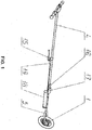
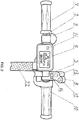
- FIGS. 1 - 5 Structure of one of the options for design of the vehicle is clarified in the drawings and pictures ( FIGS. 1 - 5 ):
- the vehicle consists of the framework, electric drive in form of motor located in the wheel, motor electric power supply system and braking system.
- the vehicle is driven by electric motor and planetary reducer, both integrated in the wheel 1 ( FIG.1 ).
- the planetary reducer design provides an overrunning clutch.
- the framework consists of the following parts: left-hand grip 2 ( FIG. 2 ), right-hand grip 3, beam 4 ( FIG. 1 ), fork 5, all rigidly interlinked.
- Left-hand and right-hand grips carry the following parts secured on them: monitor 6 ( FIG. 2 ), passenger's grip 7, switches unit 8, electronic alarm 9 and speed regulator handlebar 10.
- the monitor 6 has a button for energizing the vehicle 11 ( FIG. 2 ).
- Switches unit 8 has: button for actuation of the movement mode 'Cruise control' 12 ( FIG. 2 ), button for actuating the electronic alarm 13 and switch for changeover to 'Reverse' mode 14.
- Wheel's axle 1 is rigidly secured in fork 5 ( FIG. 3 ) with use of nuts and washers (not shown) .
- Wheel 1 is manufactured in form of motor-wheel and is secured in such a manner that the axle of the motor-wheel along with the electric motor stator are rigidly linked to fork 5, at that the torque is being transmitted from the electric motor rotor through the planetary reducer and overrunning clutch further to the wheel's rim.
- Beam carries secured the braking lever 15 ( FIG. 1 ) and box 16 accommodating the electrical plug connectors (not shown) connecting the controller 17 to the vehicle's other electrical equipment. Beam, underneath the controller, carries secured the battery 18 ( FIG. 1 ). Braking wire cable 19 in braid is laid along the beam from the braking lever 15 ( FIG. 1 ) and routed to the braking machine 20 ( FIG. 3 ). Braking machine 20 ( FIG. 3 ) comprises the brake pads (not shown), which upon pressing the brake lever dogs the brake disc 21 ( FIG. 3 ). Brake disc 21 secured on the wheel's hub 1. All the electric wires are secured on the beam 4 ( FIG. 1 ) and fork 5 with use of braid 22 ( FIG. 2 ). Protruding parts of the motor-wheel are covered with rubber hoods 23 ( FIG. 3 ).
- sport position Two options of operation of the vehicle are envisaged depending on user's position relative to the vehicle: sport position and stroller position.
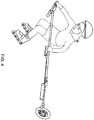
- sport position the vehicle operates as follows. User, with roller skates on, takes the vehicle in his arms, stands on a road with even and solid pavement and holds the vehicle in such a way that the beam is aside the user and the motor-wheel is behind him with the wheel's tyre standing on the road pavement.
- the monitor 6 user presses the button 11 for energizing the vehicle which feeds power supply to controller 17, the controller goes on and starts controlling all the vehicles's electric equipment.
- the monitor displays the values of parameters in digital format: 'time', 'speed', 'Mileage' and also, in graphics, 'Charge' .
- User starts turning the speed handlebar 10, wheel 1 starts rotating, and the vehicle starts moving together with the user who is rolling on roller skates.
- User controls the vehicle speed by turning the speed handlebar 10, at that the electrical control signal is being transmitted to the controller 17, and the controller increases or decreases the power fed to the electric motor integrated in the motor-wheel.
- the brake wire cable 19 is being tightened and the brake pads of the brake machine 20 come in touch with the brake disc 21.
- the wheel 1 stops rotating and obstructs further movement of the vehicle.
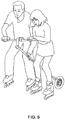
- Design of this vehicle provides additional handlebar 2 for passenger ( FIG. 2 ), at the end of which there is a passenger's grip 7.
- passenger When using the vehicle in sport position by two persons, user and passenger, in roller skates, stand from each side of the vehicle, passenger slightly bending his knees and holding on passenger handlebar and beam of the vehicle ( FIG. 5 ).
- Monitor 6 of the vehicle allows user to continuously monitor degree of battery charge. However under conditions of real-life operation, it can happen that battery charge has expired before user arrived at his destination. In such event, user proceeds moving with roller skates on in skating manner, and the vehicle freely rolls towed by user.
- Integrated in planetary reducer overrunning clutch provides easy overrunning of the wheel. On sheer descents, deenergized vehicle allows user in sport position to safely proceed at hight speed and maintain steady position and also to control the movement speed with use of brake.
- the vehicle enables user to travel not only on roller skates but also on skateboard, longboard, pennyboard, roller skis and off-road roller skates.
- the vehicle allows user to travel not only on bituminous road pavement but also on terrain and grass ones, at that user shall use roller skis with rolls of adequate size (e.g. trailskate, roll dia of not less than 150 mm) or off-road roller skates.
- the vehicle shall be fitted with additional appliances:
- Hardware and software support of the vehicle can provide following options:
- Electric motor power supply system is designed similar to that of OPTION 1, but additionally comprises the components providing operation of the recuperative braking system.
- Motor Drive consists of the electric drive in form of motor-wheel with the motor electric power supply system.
- Motor-wheel is fitted with electric motor.
- the motor-wheel uses planetary reducer and overrunning clutch.
- This configuration version of the vehicle is compatible with recuperative braking system.
- Motor electric power supply system is designed similar to OPTION 1, but additionally, it can comprise the components providing operation of recuperative braking system.
- the electric drive in form of electric motor, reducer and electric power supply system are used secured on the framework.
- This configuration version of the vehicle is compatible with recuperative braking system.
- Motor electric power supply system is designed similar to OPTION 1, but additionally, it can comprise the components providing operation of recuperative braking system.
- the internal combustion engine and reducer are used secured on the framework.
- the framework comprises one beam, and at one end the beam is fitted with a fork with a wheel secured therein; another end of the beam is fitted with left-hand and right-hand grips of different length.
- one grip On the vehicle with two grips, one grip is intended for user and another for passenger. User shall keep the wheel in a vertical position and, for creation of torque, it is in some cases expedient to make his handle longer.
- Both grips, beam and fork are rigidly interlinked.
- the framework comprises one beam.
- One end of the beam is fitted with a fork with a wheel secured therein.
- Another end of the beam is bent and parallel to the wheel rotation axle and serves as a grip, at that the grip as an individual component of the framework's structure is absent. In such configuration of the framework, towing of passenger is not envisaged.
- framework comprises one beam; and, at one end of the beam, the fork is fitted in which the wheel is secured; and its another end the beam is fitted with left-hand and right-hand grips; at that, the beam has bends allowing to place the fork with the wheel behind user keeping the wheel's rim in a plane parallel to the movement direction line.
- the framework comprises one beam, and at one end the beam is fitted with a fork with a wheel secured therein; another end of the beam is fitted with left-hand and right-hand collapsible grips.
- the option to collapse the grips allows to decrease the vehicle's size during its transport.
- the framework comprises one beam, and the beam can be collapsed.
- the option to collapse the beam allows to decrease the vehicle's size during its transport.
- the framework comprises not less than one beam, and the one beam is fabricated from a pipe rod the inner space of which is used for laying the electric cables. This version of the framework allows to reduce probability of damages to cable network of the vehicle in emergencies.
- the framework carries assemblies for securing the detachable container for transporting of cargoes.
- the framework comprises one beam.
- One end of the beam is fitted with a fork with a wheel secured therein.
- Another end of the beam is fitted with overhang positioned in the plane parallel to the wheel's rotation plane, rudder is secured in the overhang.
- Rudder, overhang, beam and fork are rigidly interlinked.
- the framework comprises one beam.
- One end of the beam is fitted with a fork with a wheel secured therein.
- Another end of the beam is fitted with a stem secured and oriented in the plane parallel to the wheel's rotation plane.
- the overhang is fitted with asymmetrical rudder secured therein, right-hand grip of which is oriented parallel to the wheel's rotation plane; and left-hand grip has a bend which allows the end of the left-hand grip to be oriented perpendicular to the wheel's rotation plane, at that the end of the left-hand grip, in working position, is oriented vertically.
- Rudder, overhang, beam and fork are rigidly interlinked.
- the framework comprises one beam. At one end, the beam is fitted with a fork with a wheel secured therein. The second end of the beam is fitted with a rudder. The central part of the beam is fitted with a supporting handlebar so that the central line of the supporting handlebar is parallel to the wheel rotation plane. The supporting handlebar diverges from the beam at an angle, owing to this, in working position, the supporting handlebar is oriented horizontally. Rudder, beam, supporting handlebar and fork are rigidly interlinked. Supporting handlebar is used when the vehicle is exploited in sport position or for hand carriage of the vehicle.
- the framework comprises one beam with a wheel secured therein at one end; another end of the beam is fitted with a rudder; and the beam has several bends in the plane parallel to the wheel rotation plane, at that, in the middle part of the beam, there is a linear span at which the supporting handlebar is secured, and the bends of the beam are made so that in working position the supporting handlebar is oriented horizontally.
- Rudder, beam, supporting handlebar and fork are rigidly interlinked. Supporting handlebar is used when the vehicle is exploited in sport position or for hand carriage of the vehicle.
- the vehicle with an electric drive as per techniques of charging and recharging can be configured in several options:
- the vehicle has electric drive comprising. Electric drive, for an electric power source, exploits batteries or supercapacitors, and the power sources are non-detachable. For charging the power sources, the vehicle shall be connected, through a special plug connector, to charging device.
- the vehicle has electric drive comprising.
- electric drive exploits detachable battery.
- the battery shall be detached from the vehicle and connected to charging device.
- the vehicle has electric drive comprising, among others, the recuperative braking system.
- Recuperative braking system provides, during braking, conversion of mechanical energy of the vehicle and user into electric energy. Generated, as a result of braking, electric energy charges the battery.
- Recuperative braking system is based on the property of reversibility of electric machines.
- electric motor operates in generator mode creating the required moment of resistance and thus providing braking of rotor part. Electric energy is generated by motor-generator either on account of potential energy of the vehicle during its movement on descent or on account of kinetic energy while the vehicle's slowing down.
- This configuration version of the vehicle is compatible with the drive options: OPTION 2, OPTION 3 and OPTION 4.
- the vehicle has electric drive which comprises, among other, solar cell, charge controller and electric power source. On account of solar energy, the solar cell charges or recharges the electric power source.
- This configuration version of the vehicle is compatible with the drive options: OPTION 1, OPTION 2, OPTION 3 and OPTION 4.
- the vehicle can be configured in several options:
- the vehicle's braking system provides brake lever pressing of which by user initiates braking.
- Brake lever can be positioned on the vehicle at several places. Probably the optimal place would be the middle part of the beam.
- the right-hand handlebar when the vehicle is used in sport mode, the right-hand handlebar is fitted with a speed grip, and user holds on it with his right hand, and his left hand grips the beam in its central part; and in this very area the brake lever is being fitted, at that, user can, while keeping the beam in his left hand, grip with his fingers the brake lever and implement braking.
- different control functions are distributed between the user's hands: right hand is responsible for controlling the motor's power, left hand - for braking.
- the vehicle's braking system provides brake lever pressing of which by user initiates braking.
- the brake lever is fitted on the supporting handlebar.
- the right-hand handlebar is fitted with a speed grip, and user holds on it with his right hand, and his left hand grips the supporting handlebar where the brake lever is also being fitted; at that, user can, while keeping the supporting handlebar in his left hand, grip with his fingers the brake lever and implement braking.
- different control functions are distributed between user's hands: right hand is responsible for controlling the motor's power, left hand - for braking.
- the vehicle's braking system provides two brake levers, pressing of each of them by user initiates braking.
- One of the brake levers is fitted in the middle part of the beam on the supporting handlebar, another is fitted on the left handlebar.
- user effects braking with the brake lever fitted in the middle part of the beam.
- the wheel is in front of user; user holds the speed grip with left hand, and with right hand he holds on the 'left grip' which is now on the right from him.
- stroller position user brakes with use of brake lever which is installed on the 'left handlebar'.
- the vehicle's braking system provides brake lever pressing of which by user initiates braking.
- arrangement of the brake lever is classical as on scooters and motor-bikes - the brake lever is installed above the speed grip.
- Rim brakes are used on the vehicle as a part of braking system. Rim brakes operate on account of pressing of the pads to the wheel's rim. Pads are being secured on brake levers which, in turn, are secured moveably on the framework. Upon pressing the brake lever, the brake wire cable is being tightened and the movement of the brake wire cable is transmitted to the pads, and the pads get in contact with the wheel's rim.
- Disc brakes are used on the vehicle as a part of braking system. Disc brakes operate on the account of pressing the pads to the brake disc which is secured on the wheel's bushing. The pads are located inside the braking machine which is secured on the fork. Upon pressing the brake lever, the brake wire cable is being tightened and the movement of the brake wire cable is transmitted to the braking machine which brings in action the pads, and the pads get in contact with the braking disc.
- the invention allows to simplify the design, make the travelling process safer, increase the cruising range and travel speed.
Landscapes
- Engineering & Computer Science (AREA)
- Mechanical Engineering (AREA)
- Transportation (AREA)
- Chemical & Material Sciences (AREA)
- Combustion & Propulsion (AREA)
- Power Engineering (AREA)
- Life Sciences & Earth Sciences (AREA)
- Sustainable Development (AREA)
- Sustainable Energy (AREA)
- Motorcycle And Bicycle Frame (AREA)
- Electric Propulsion And Braking For Vehicles (AREA)
Applications Claiming Priority (2)
| Application Number | Priority Date | Filing Date | Title |
|---|---|---|---|
| RU2014141340/11A RU2600557C2 (ru) | 2014-10-15 | 2014-10-15 | Способ передвижения и транспортное средство для реализации способа (варианты) |
| PCT/RU2014/000880 WO2016060585A1 (ru) | 2014-10-15 | 2014-11-21 | Транспортное средство |
Publications (2)
| Publication Number | Publication Date |
|---|---|
| EP3207965A1 true EP3207965A1 (de) | 2017-08-23 |
| EP3207965A4 EP3207965A4 (de) | 2018-06-27 |
Family
ID=55747008
Family Applications (1)
| Application Number | Title | Priority Date | Filing Date |
|---|---|---|---|
| EP14904150.1A Withdrawn EP3207965A4 (de) | 2014-10-15 | 2014-11-21 | Beförderungsart |
Country Status (4)
| Country | Link |
|---|---|
| US (1) | US10392057B2 (de) |
| EP (1) | EP3207965A4 (de) |
| RU (1) | RU2600557C2 (de) |
| WO (1) | WO2016060585A1 (de) |
Cited By (1)
| Publication number | Priority date | Publication date | Assignee | Title |
|---|---|---|---|---|
| CN108437804A (zh) * | 2018-02-05 | 2018-08-24 | 浙江齐享科技有限公司 | 一种共享电动助力车的充电方法及系统 |
Families Citing this family (11)
| Publication number | Priority date | Publication date | Assignee | Title |
|---|---|---|---|---|
| US10676169B2 (en) | 2015-02-09 | 2020-06-09 | Powerstick, Inc. | Systems and methods for recreational propulsion device |
| CN109562291A (zh) * | 2016-01-31 | 2019-04-02 | 酷飞创新有限公司 | 具有直观控制的基于脚踏板的动力车辆 |
| WO2017222416A1 (ru) * | 2016-06-22 | 2017-12-28 | Дмитрий Николаевич ХАРИТОНОВ | Гибридное электрическое транспортное средство |
| RU175294U1 (ru) * | 2016-06-22 | 2017-11-29 | Юрий Леонидович Козаков | Одноколесное моторизованное средство передвижения |
| US10718344B2 (en) * | 2017-02-20 | 2020-07-21 | John Christian Colley | Human graspable propulsion device |
| US10179273B2 (en) * | 2017-02-20 | 2019-01-15 | John Christian Colley | Graspable human propulsion device |
| US9950244B1 (en) * | 2017-02-28 | 2018-04-24 | Raman Sargis | Motorized wheel assembly |
| US20180257486A1 (en) * | 2017-03-08 | 2018-09-13 | Ampstick, Inc. | Auxiliary propulsion system |
| RU2656781C1 (ru) * | 2017-08-18 | 2018-06-06 | Владимир Сергеевич Черкашин | Рулевая стойка и индивидуальное транспортное средство на ее основе |
| JP6841752B2 (ja) * | 2017-12-18 | 2021-03-10 | 株式会社シマノ | 報知システム |
| RU194050U1 (ru) * | 2019-07-04 | 2019-11-26 | Андрей Александрович Горшков | Электропривод к роликовым конькам |
Family Cites Families (42)
| Publication number | Priority date | Publication date | Assignee | Title |
|---|---|---|---|---|
| US3797446A (en) * | 1972-12-19 | 1974-03-19 | R Cibula | Mobile power unit |
| JPS604031B2 (ja) * | 1980-10-17 | 1985-02-01 | 彰 桑原 | スポ−ツ、遊戯用原動機付一輪車 |
| GB2246751B (en) * | 1990-07-05 | 1994-06-15 | Frank Cecil Kneale | Motorised vehicle |
| US5106136A (en) * | 1991-07-12 | 1992-04-21 | Crain William E | Motorcycle bumper system |
| IT1265672B1 (it) * | 1993-03-17 | 1996-11-22 | Fabrizio Lucernoni | Dispositivo propulsore per una persona su pattini a rotelle. |
| US5385210A (en) * | 1994-02-01 | 1995-01-31 | Harvey; William B. | Tow vehicle system |
| USD372000S (en) * | 1995-03-06 | 1996-07-23 | Searles Andrew N | Motorized pushing device |
| US5687991A (en) * | 1995-08-23 | 1997-11-18 | Gairdner; James R. | Method and apparatus for braking skates and the like |
| WO1997018866A1 (en) * | 1995-11-17 | 1997-05-29 | Dempster Harry E | Portable, power-drive unit and accessory attachment |
| US5938240A (en) * | 1996-02-09 | 1999-08-17 | Gairdner; James R. | Control device and method for wheeled skates and the like |
| US5721473A (en) * | 1996-04-18 | 1998-02-24 | Devries; Leroy Milo | Electric motorized vehicular wheel with adjuncts |
| NL1008786C1 (nl) * | 1998-04-02 | 1999-10-05 | Metje Eerkens De Graaf | Werkwijze en inrichting voor het helpen voortbewegen van rijders op rolschaatsen, fietsen en rolwagens. |
| DE19819381A1 (de) * | 1998-04-30 | 2000-04-20 | Helmut Ruh | Einrichtung zum Ziehen eines Menschen auf einer Roll- oder Gleiteinrichtung |
| US6100615A (en) * | 1998-05-11 | 2000-08-08 | Birkestrand; Orville J. | Modular motorized electric wheel hub assembly for bicycles and the like |
| DE19902963A1 (de) * | 1999-01-26 | 1999-07-15 | Antonio Timm | Zugmaschine für Personen, die sich auf Rollen, Kufen oder Gleitbrettern fortbewegen |
| US6467559B1 (en) * | 1999-02-05 | 2002-10-22 | Motoroller Propulsion Company, Inc. | Propulsion device and method of use |
| RU2153749C1 (ru) * | 1999-11-11 | 2000-07-27 | Максимов Александр Иванович | Способ прокладки кабеля (провода) в кабелепроводном устройстве |
| US6321863B1 (en) * | 2000-06-26 | 2001-11-27 | Mac Brushless Motor Company | Hub motor for a wheeled vehicle |
| FR2812213B1 (fr) * | 2000-07-27 | 2003-01-03 | Marc Pugnet | Dispositif d'entrainement pour utilisateur de patins a roulettes |
| US20020094906A1 (en) * | 2001-01-12 | 2002-07-18 | Jordan Brian T. | Automatic bicycle shifting system |
| US6820710B2 (en) * | 2001-09-12 | 2004-11-23 | Bryan W. Fechner | Motorcycle cruise control system with brake release |
| US20050045392A1 (en) * | 2002-07-31 | 2005-03-03 | Maslov Boris A. | In-wheel electric motors |
| US7125080B1 (en) * | 2002-10-23 | 2006-10-24 | Electric Mobility Corporation | Foldable armrest for chair |
| EP1641542A1 (de) * | 2003-06-27 | 2006-04-05 | Michel Humeau | Handrollgerät für rollschuh-fahrer |
| US8297148B1 (en) * | 2004-08-30 | 2012-10-30 | Thomas Ferguson | Modular adjustable handlebar kit |
| US20060131084A1 (en) * | 2004-12-22 | 2006-06-22 | Fred Rupp | Motorized handle |
| RU52724U1 (ru) * | 2005-04-20 | 2006-04-27 | Юрий Афанасьевич Хукаленко | Устройство для передвижения человека |
| US20080257628A1 (en) * | 2006-06-28 | 2008-10-23 | Bouncing Brain Innovations Season Two Subsidiary 12, Llc | Lightweight propulsion device for providing motive force to a skate equipment user |
| US20110017539A1 (en) * | 2006-06-28 | 2011-01-27 | William Pitt | Lightweight propulsion device for providing motive force to a skate equipment user |
| US7883136B2 (en) * | 2007-01-17 | 2011-02-08 | Polaris Industries Inc. | Two-wheeled vehicle |
| US7497285B1 (en) * | 2007-11-15 | 2009-03-03 | Vladimir Radev | Hybrid electric vehicle |
| CN101157340A (zh) * | 2007-11-28 | 2008-04-09 | 郭树阳 | 自发电蓄电电动汽车 |
| WO2009152556A1 (en) * | 2008-05-08 | 2009-12-23 | Malcolm Leonard Stephen Dean | An epicyclic transmission |
| US20100072726A1 (en) * | 2008-09-22 | 2010-03-25 | Jared Madsen | Systems and Methods for Providing a Bicycle with Large Load Carrying Capacity |
| EP2450220A1 (de) * | 2009-07-03 | 2012-05-09 | Zakrytoe Aktzionernoye Obschestvo Nauchno-Proizvodstevvnoe Predriyatie "Inkar-M" | Elektrofahrzeug |
| US9586471B2 (en) * | 2013-04-26 | 2017-03-07 | Carla R. Gillett | Robotic omniwheel |
| US20110266077A1 (en) * | 2010-04-29 | 2011-11-03 | Claude Nadeau | Autonomous propulsion system |
| US8403085B1 (en) * | 2010-09-13 | 2013-03-26 | Timothy A. Gilbert | Power application device |
| WO2012111049A1 (ja) * | 2011-02-14 | 2012-08-23 | Shimada Toshiaki | 歯車装置及び駆動装置 |
| EP2703264A1 (de) * | 2012-08-28 | 2014-03-05 | Reelight APS | Wirbelstromerzeuger für Fahrzeuge |
| US9660500B2 (en) * | 2013-11-14 | 2017-05-23 | Razor Usa Llc | Hub motor arrangement or vehicle with hub motor arrangement |
| US10005317B2 (en) * | 2014-04-04 | 2018-06-26 | Superpedestrian, Inc. | Devices and methods of thermal management for a motorized wheel |
-
2014
- 2014-10-15 RU RU2014141340/11A patent/RU2600557C2/ru active
- 2014-11-21 WO PCT/RU2014/000880 patent/WO2016060585A1/ru not_active Ceased
- 2014-11-21 EP EP14904150.1A patent/EP3207965A4/de not_active Withdrawn
-
2017
- 2017-04-13 US US15/486,690 patent/US10392057B2/en active Active
Cited By (1)
| Publication number | Priority date | Publication date | Assignee | Title |
|---|---|---|---|---|
| CN108437804A (zh) * | 2018-02-05 | 2018-08-24 | 浙江齐享科技有限公司 | 一种共享电动助力车的充电方法及系统 |
Also Published As
| Publication number | Publication date |
|---|---|
| US20170217511A1 (en) | 2017-08-03 |
| WO2016060585A1 (ru) | 2016-04-21 |
| RU2014141340A (ru) | 2016-05-10 |
| RU2600557C2 (ru) | 2016-10-20 |
| US10392057B2 (en) | 2019-08-27 |
| EP3207965A4 (de) | 2018-06-27 |
Similar Documents
| Publication | Publication Date | Title |
|---|---|---|
| US10392057B2 (en) | Vehicle | |
| US8616313B2 (en) | Motorized transport vehicle for a pedestrian | |
| JP5927677B2 (ja) | 全輪駆動システムを有する2輪車 | |
| CN103261014B (zh) | 可通过重量转移控制的具有两件式行驶踏板的交通工具 | |
| US20110291462A1 (en) | Motor assembly for two wheeled vehicle | |
| WO2017081523A1 (en) | Self-balancing single wheel board with anti-fall and brake safety systems | |
| US10583877B2 (en) | Torque stick apparatus and methods of use | |
| US20220063758A1 (en) | Integrated head tube steering motor for autonomous electronic bicycle | |
| CN105984537A (zh) | 可倾斜机动三轮车 | |
| WO2015191536A1 (en) | Variable resistance serial hybrid electric vehicle | |
| CN204713296U (zh) | 具有宽胎的冲浪式平衡车 | |
| CN204587210U (zh) | 电动滑板车 | |
| CN204473001U (zh) | 滑板式平衡车 | |
| US20150075883A1 (en) | Apparatus And Method Of Powering A Wheeled Vehicle | |
| US20210070294A1 (en) | Brake-steering apparatus for controlling autonomous navigation of an electric scooter | |
| CN112389532A (zh) | 智能助力婴儿车 | |
| US20170101145A1 (en) | Electric Tricycle Conversion Kit | |
| JP5578627B2 (ja) | 4輪自転車の後輪駆動緩衝装置 | |
| CN204998686U (zh) | 便携式电动车 | |
| JP3197342U (ja) | 電動2輪荷車 | |
| UA126426C2 (uk) | Електричний транспортний засіб, який балансується (варіанти) | |
| UA129502C2 (uk) | Електричний транспортний засіб, який балансується (варіанти) | |
| GB2429684A (en) | Electric vehicle with front wheel drive and human power | |
| CN203996631U (zh) | 具有音乐闪光功能的购物篮休闲运动车 | |
| CN211810024U (zh) | 一种单侧滑行的独轮车 |
Legal Events
| Date | Code | Title | Description |
|---|---|---|---|
| STAA | Information on the status of an ep patent application or granted ep patent |
Free format text: STATUS: THE INTERNATIONAL PUBLICATION HAS BEEN MADE |
|
| PUAI | Public reference made under article 153(3) epc to a published international application that has entered the european phase |
Free format text: ORIGINAL CODE: 0009012 |
|
| STAA | Information on the status of an ep patent application or granted ep patent |
Free format text: STATUS: REQUEST FOR EXAMINATION WAS MADE |
|
| 17P | Request for examination filed |
Effective date: 20170428 |
|
| AK | Designated contracting states |
Kind code of ref document: A1 Designated state(s): AL AT BE BG CH CY CZ DE DK EE ES FI FR GB GR HR HU IE IS IT LI LT LU LV MC MK MT NL NO PL PT RO RS SE SI SK SM TR |
|
| AX | Request for extension of the european patent |
Extension state: BA ME |
|
| A4 | Supplementary search report drawn up and despatched |
Effective date: 20180528 |
|
| RIC1 | Information provided on ipc code assigned before grant |
Ipc: B60K 35/00 20060101ALI20180522BHEP Ipc: B60L 11/18 20060101ALI20180522BHEP Ipc: A63C 17/00 20060101ALI20180522BHEP Ipc: B62D 51/02 20060101ALI20180522BHEP Ipc: B62M 6/90 20100101ALI20180522BHEP Ipc: B60T 7/10 20060101ALI20180522BHEP Ipc: B60L 15/30 20060101ALI20180522BHEP Ipc: B62M 6/45 20100101ALI20180522BHEP Ipc: B60L 7/10 20060101ALI20180522BHEP Ipc: A63C 17/12 20060101AFI20180522BHEP Ipc: B60K 7/00 20060101ALI20180522BHEP |
|
| RIC1 | Information provided on ipc code assigned before grant |
Ipc: B62M 6/45 20100101ALI20191204BHEP Ipc: B60L 53/80 20190101ALI20191204BHEP Ipc: B62D 51/02 20060101ALI20191204BHEP Ipc: B60K 7/00 20060101ALI20191204BHEP Ipc: B60T 7/10 20060101ALI20191204BHEP Ipc: B60L 15/30 20060101ALI20191204BHEP Ipc: B60L 53/16 20190101ALI20191204BHEP Ipc: B60K 35/00 20060101ALI20191204BHEP Ipc: B62M 6/90 20100101ALI20191204BHEP Ipc: A63C 17/00 20060101ALI20191204BHEP Ipc: A63C 17/12 20060101AFI20191204BHEP Ipc: B60L 7/10 20060101ALI20191204BHEP Ipc: B60L 50/60 20190101ALI20191204BHEP |
|
| STAA | Information on the status of an ep patent application or granted ep patent |
Free format text: STATUS: EXAMINATION IS IN PROGRESS |
|
| 17Q | First examination report despatched |
Effective date: 20200311 |
|
| RIC1 | Information provided on ipc code assigned before grant |
Ipc: B62D 51/02 20060101ALI20210813BHEP Ipc: B60L 53/80 20190101ALI20210813BHEP Ipc: B60L 53/16 20190101ALI20210813BHEP Ipc: B60L 50/60 20190101ALI20210813BHEP Ipc: A63C 17/12 20060101ALI20210813BHEP Ipc: B62K 1/00 20060101ALI20210813BHEP Ipc: B62K 11/00 20060101AFI20210813BHEP |
|
| GRAP | Despatch of communication of intention to grant a patent |
Free format text: ORIGINAL CODE: EPIDOSNIGR1 |
|
| STAA | Information on the status of an ep patent application or granted ep patent |
Free format text: STATUS: GRANT OF PATENT IS INTENDED |
|
| INTG | Intention to grant announced |
Effective date: 20211213 |
|
| STAA | Information on the status of an ep patent application or granted ep patent |
Free format text: STATUS: THE APPLICATION IS DEEMED TO BE WITHDRAWN |
|
| 18D | Application deemed to be withdrawn |
Effective date: 20220426 |