EP3207980A1 - Dispositif de mélange de fluides - Google Patents
Dispositif de mélange de fluides Download PDFInfo
- Publication number
- EP3207980A1 EP3207980A1 EP15851470.3A EP15851470A EP3207980A1 EP 3207980 A1 EP3207980 A1 EP 3207980A1 EP 15851470 A EP15851470 A EP 15851470A EP 3207980 A1 EP3207980 A1 EP 3207980A1
- Authority
- EP
- European Patent Office
- Prior art keywords
- flow channel
- flow
- fluid
- mixing device
- units
- Prior art date
- Legal status (The legal status is an assumption and is not a legal conclusion. Google has not performed a legal analysis and makes no representation as to the accuracy of the status listed.)
- Withdrawn
Links
- 239000012530 fluid Substances 0.000 title claims abstract description 150
- 238000009434 installation Methods 0.000 abstract description 9
- 239000003153 chemical reaction reagent Substances 0.000 description 6
- 238000010586 diagram Methods 0.000 description 3
- 230000000694 effects Effects 0.000 description 2
- 239000000203 mixture Substances 0.000 description 2
- 230000004048 modification Effects 0.000 description 2
- 238000012986 modification Methods 0.000 description 2
- 239000008280 blood Substances 0.000 description 1
- 210000004369 blood Anatomy 0.000 description 1
- 239000000446 fuel Substances 0.000 description 1
- 239000007788 liquid Substances 0.000 description 1
- 238000009751 slip forming Methods 0.000 description 1
- XLYOFNOQVPJJNP-UHFFFAOYSA-N water Substances O XLYOFNOQVPJJNP-UHFFFAOYSA-N 0.000 description 1
Images




Classifications
-
- B—PERFORMING OPERATIONS; TRANSPORTING
- B01—PHYSICAL OR CHEMICAL PROCESSES OR APPARATUS IN GENERAL
- B01F—MIXING, e.g. DISSOLVING, EMULSIFYING OR DISPERSING
- B01F33/00—Other mixers; Mixing plants; Combinations of mixers
- B01F33/30—Micromixers
- B01F33/301—Micromixers using specific means for arranging the streams to be mixed, e.g. channel geometries or dispositions
-
- B—PERFORMING OPERATIONS; TRANSPORTING
- B01—PHYSICAL OR CHEMICAL PROCESSES OR APPARATUS IN GENERAL
- B01F—MIXING, e.g. DISSOLVING, EMULSIFYING OR DISPERSING
- B01F25/00—Flow mixers; Mixers for falling materials, e.g. solid particles
- B01F25/40—Static mixers
- B01F25/42—Static mixers in which the mixing is affected by moving the components jointly in changing directions, e.g. in tubes provided with baffles or obstructions
- B01F25/43—Mixing tubes, e.g. wherein the material is moved in a radial or partly reversed direction
- B01F25/432—Mixing tubes, e.g. wherein the material is moved in a radial or partly reversed direction with means for dividing the material flow into separate sub-flows and for repositioning and recombining these sub-flows; Cross-mixing, e.g. conducting the outer layer of the material nearer to the axis of the tube or vice-versa
- B01F25/4321—Mixing tubes, e.g. wherein the material is moved in a radial or partly reversed direction with means for dividing the material flow into separate sub-flows and for repositioning and recombining these sub-flows; Cross-mixing, e.g. conducting the outer layer of the material nearer to the axis of the tube or vice-versa the subflows consisting of at least two flat layers which are recombined, e.g. using means having restriction or expansion zones
-
- B—PERFORMING OPERATIONS; TRANSPORTING
- B01—PHYSICAL OR CHEMICAL PROCESSES OR APPARATUS IN GENERAL
- B01F—MIXING, e.g. DISSOLVING, EMULSIFYING OR DISPERSING
- B01F25/00—Flow mixers; Mixers for falling materials, e.g. solid particles
- B01F25/40—Static mixers
- B01F25/42—Static mixers in which the mixing is affected by moving the components jointly in changing directions, e.g. in tubes provided with baffles or obstructions
- B01F25/421—Static mixers in which the mixing is affected by moving the components jointly in changing directions, e.g. in tubes provided with baffles or obstructions by moving the components in a convoluted or labyrinthine path
-
- B—PERFORMING OPERATIONS; TRANSPORTING
- B01—PHYSICAL OR CHEMICAL PROCESSES OR APPARATUS IN GENERAL
- B01F—MIXING, e.g. DISSOLVING, EMULSIFYING OR DISPERSING
- B01F33/00—Other mixers; Mixing plants; Combinations of mixers
- B01F33/30—Micromixers
-
- B—PERFORMING OPERATIONS; TRANSPORTING
- B01—PHYSICAL OR CHEMICAL PROCESSES OR APPARATUS IN GENERAL
- B01L—CHEMICAL OR PHYSICAL LABORATORY APPARATUS FOR GENERAL USE
- B01L3/00—Containers or dishes for laboratory use, e.g. laboratory glassware; Droppers
- B01L3/50—Containers for the purpose of retaining a material to be analysed, e.g. test tubes
- B01L3/502—Containers for the purpose of retaining a material to be analysed, e.g. test tubes with fluid transport, e.g. in multi-compartment structures
-
- B—PERFORMING OPERATIONS; TRANSPORTING
- B01—PHYSICAL OR CHEMICAL PROCESSES OR APPARATUS IN GENERAL
- B01F—MIXING, e.g. DISSOLVING, EMULSIFYING OR DISPERSING
- B01F2101/00—Mixing characterised by the nature of the mixed materials or by the application field
- B01F2101/2202—Mixing compositions or mixers in the medical or veterinary field
-
- B—PERFORMING OPERATIONS; TRANSPORTING
- B01—PHYSICAL OR CHEMICAL PROCESSES OR APPARATUS IN GENERAL
- B01F—MIXING, e.g. DISSOLVING, EMULSIFYING OR DISPERSING
- B01F2101/00—Mixing characterised by the nature of the mixed materials or by the application field
- B01F2101/23—Mixing of laboratory samples e.g. in preparation of analysing or testing properties of materials
-
- B—PERFORMING OPERATIONS; TRANSPORTING
- B01—PHYSICAL OR CHEMICAL PROCESSES OR APPARATUS IN GENERAL
- B01L—CHEMICAL OR PHYSICAL LABORATORY APPARATUS FOR GENERAL USE
- B01L2200/00—Solutions for specific problems relating to chemical or physical laboratory apparatus
- B01L2200/16—Reagents, handling or storing thereof
-
- B—PERFORMING OPERATIONS; TRANSPORTING
- B01—PHYSICAL OR CHEMICAL PROCESSES OR APPARATUS IN GENERAL
- B01L—CHEMICAL OR PHYSICAL LABORATORY APPARATUS FOR GENERAL USE
- B01L2300/00—Additional constructional details
- B01L2300/08—Geometry, shape and general structure
- B01L2300/0861—Configuration of multiple channels and/or chambers in a single devices
- B01L2300/0864—Configuration of multiple channels and/or chambers in a single devices comprising only one inlet and multiple receiving wells, e.g. for separation, splitting
-
- B—PERFORMING OPERATIONS; TRANSPORTING
- B01—PHYSICAL OR CHEMICAL PROCESSES OR APPARATUS IN GENERAL
- B01L—CHEMICAL OR PHYSICAL LABORATORY APPARATUS FOR GENERAL USE
- B01L2300/00—Additional constructional details
- B01L2300/08—Geometry, shape and general structure
- B01L2300/0861—Configuration of multiple channels and/or chambers in a single devices
- B01L2300/0867—Multiple inlets and one sample wells, e.g. mixing, dilution
-
- B—PERFORMING OPERATIONS; TRANSPORTING
- B01—PHYSICAL OR CHEMICAL PROCESSES OR APPARATUS IN GENERAL
- B01L—CHEMICAL OR PHYSICAL LABORATORY APPARATUS FOR GENERAL USE
- B01L2300/00—Additional constructional details
- B01L2300/08—Geometry, shape and general structure
- B01L2300/0887—Laminated structure
Definitions
- the present invention relates to a fluid mixing device that mixes a plurality of inflow fluids and makes the mixed fluid flow out.
- a micro-mixer or a micro-reactor that mixes a sample of human body ingesta or the like with a reagent to chemically react or analyze the sample can be given.
- a flow channel is formed by providing a groove in a flow channel plate.
- the flow channel is provided with two inflow paths for respectively introducing a sample and a reagent and one outflow path and is made such that the sample and the reagent introduced into the two inflow paths join together and are led to the outflow path.
- Patent Literature 1 Japanese Unexamined Patent Application Publication No. 2008-284626
- the flow channel of the fluid mixing device disclosed in Patent Literature 1 is planar, and the sample and the reagent join together from the two inflow paths and flow in one direction to the outflow path.
- a planar flow channel there is a problem in which mixing efficiency is poor, even though fluids join together.
- the installation area increases.
- the present invention is to solve the problem in the related art and has an object to provide a fluid mixing device in which it is possible to efficiently enhance the mixing rate of fluids without excessively increasing the installation area.
- a fluid mixing device that mixes a plurality of fluids, including: a plurality of flow channel units disposed to be divided in a plurality of layers, in which each of the flow channel units has an inflow port, an outflow port, and a plurality of branch flow channels making the inflow port and the outflow port communicate with each other, the inflow port of the flow channel unit on one side, out of the flow channel units which are located in different layers, and the outflow port of the flow channel unit on the other side are connected to each other, whereby a three-dimensional flow channel is configured, and when a direction from the inflow port to the outflow port is set to be a flow direction of the fluid in each of the flow channel units, the flow directions intersect each other between the respective layers.
- the fluid mixing device if a plurality of fluids are introduced, diverging, joining, and a change in direction are repeated through the respective flow channel units of the three-dimensional flow channel, and therefore, it is possible to efficiently mix the fluids and make the mixed fluid flow out.
- the flow directions in the flow channel units intersect each other between the respective layers, and therefore, every time the fluid flows through the flow channel unit of each layer, the fluid can be divided in different directions and the divided fluids can be joined together, and the division and the joining can be repeated with a direction changed. In this way, it is possible to greatly improve the mixing efficiency of a plurality of fluids.
- the flow channel unit is disposed in each layer, and therefore, the number of flow channel units can be increased by increasing the number of layers. In this way, it is possible to efficiently increase the mixing efficiency of a plurality of fluids without changing the installation area.
- the flow directions in the connected flow channel units are orthogonal to each other.
- the flow directions in the flow channel units disposed in different layers are made to be orthogonal to each other, whereby it is possible to make the fluid be branched in an orthogonal direction when the fluid flows from one flow channel unit to the next flow channel unit, and thus it is possible to increase the mixing efficiency of the fluid.
- the branch flow channels of the flow channel unit are configured with two first flow channels which divide the fluid flowing in from the inflow port into two fluid flows and lead the split fluids in directions in which the split fluids become more distant from each other, and two second flow channels which turn the split fluids from the respective first flow channels so as to lead the split fluids in directions in which the split fluids approach each other, and make the split fluids join together.
- an angle between the two first flow channels is an angle greater than 90 degrees and less than or equal to 180 degrees and an angle between the two second flow channels is an angle smaller than 180 degrees. Further, it is preferable that the first flow channels and the second flow channels are straight lines or curved lines.
- a plurality of the flow channel units are disposed in at least one of the layers.
- At least two of the layers having the plurality of flow channel units are stacked.
- the fluid mixing device can have a configuration in which a plurality of flow channel plates are laminated to be stacked in a thickness direction thereof, the flow channel unit is formed between a groove formed in a surface of the flow channel plate on one side and a flat surface of the flow channel plate on the other side which is stacked on the flow channel plate on one side, and three or more of the flow channel plates are stacked, whereby the plurality of layers are formed.
- the flow directions in the flow channel units intersect each other between the respective layers, and therefore, every time the fluid flows through the flow channel unit of each layer, the fluid can be divided, and furthermore, such division and convergence of the fluid can be repeated while changing a direction. Accordingly, it is possible to greatly improve the mixing efficiency of a plurality of fluids. Further, the number of flow channel units can be increased by increasing the number of layers, and therefore, it is possible to increase the mixing efficiency of the fluid without widening the plane area.
- fluid mixing device that mixes a reagent with a human body ingesta sample such as blood is taken as an example.
- fluids to be mixed are not limited thereto.
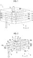
- Fig. 1 is an external perspective view showing the overall configuration of a fluid mixing device 1 according to an embodiment of the present invention
- Fig. 2 is a diagram showing the shape of a three-dimensional flow channel which is formed inside of the fluid mixing device 1.
- the fluid mixing device 1 shown in Fig. 1 is provided with a fluid inlet 2 provided at the uppermost part thereof and a fluid outlet 3 provided at the lowermost part.
- the fluid inlet 2 and the fluid outlet 3 communicate with a three-dimensional flow channel 4 formed inside of the fluid mixing device 1. If a plurality of fluids are introduced from the fluid inlet 2, the fluids are mixed in the three-dimensional flow channel 4 and the mixed fluid is discharged from the fluid outlet 3.
- the three-dimensional flow channel 4 is configured of a plurality of flow channel units 20 disposed in a plurality of layers arranged in an up-and-down direction.
- the flow channel units 20 are configured in the same basic shape and disposed to be divided in a plurality of layers.
- seven flow channel units 20 are disposed to be divided in four layers.
- the individual flow channel units are described to be denoted by reference numerals 20a to 20g.
- the fluid flows through the flow channel unit 20a, the flow channel unit 20b, the flow channel unit 20c, the flow channel unit 20d, the flow channel unit 20e, the flow channel unit 20f, and the flow channel unit 20g in this order and is discharged from the fluid outlet 3.
- one flow channel unit 20b is disposed in the first layer, and two flow channel units 20a and 20c are disposed in the second layer.
- Two flow channel units 20f and 20d are disposed in the third layer, and two flow channel units 20e and 20g are disposed in the fourth layer.
- Fig. 3 is a perspective view showing the basic shape of the flow channel unit 20 in this embodiment
- Fig. 4 is a plan view of the basic shape of the flow channel unit shown in Fig. 3 .
- each of the flow channel units 20 is provided with an inflow port 21 and an outflow port 22 and configured such that the fluid flowing in from the inflow port 21 forms a flow in one direction (here, a horizontal direction) toward the outflow port 22.
- Two branch flow channels 23 making the inflow port 21 and the outflow port 22 communicate with each other are formed on the way from the inflow port 21 to the outflow port 22.
- the branch flow channels 23 are configured with two first flow channels 23a and 23b which divide the fluid flowing in from the inflow port 21 into two fluid flows and lead the split fluids in directions in which the split fluids become more distant from each other, and two second flow channels 23c and 23d which turn the split fluids from the respective first flow channels 23a and 23b so as to lead the split fluids in directions in which the split fluids approach each other, and make the split fluids join together.
- An angle ⁇ between the first flow channels 23a and 23b is greater than 90 degrees and less than or equal to 180 degrees
- an angle P between the second flow channels 23c and 23d is smaller than 180 degrees. In this way, the split flows can turn and join together.
- the angle ⁇ between the first flow channels 23a and 23b is 180 degrees and the angle P between the second flow channels 23c and 23d is 90 degrees.
- the angle ⁇ between the first flow channels 23a and 23b is 180 degrees.
- a joining flow channel 23e for further leading the fluid joined through the second flow channels 23c and 23d to the outflow port 22 is continuously formed.
- the flow channel units 20 located in different layers are connected to each other.
- the outflow port 22 of the flow channel unit 20a is connected to the inflow port 21 of the flow channel unit 20b located in the layer above the flow channel unit 20a
- the outflow port 22 of the flow channel unit 20b is connected to the inflow port 21 of the flow channel unit 20c located in the layer below the flow channel unit 20b.
- the inflow port 21 and the flow channel port 22 are open toward either of the upper side or the lower side according to the layer to which the flow channel unit is connected.
- both the opening direction of the inflow port 21 and the opening direction of the outflow port 22 are upward.
- the opening direction of the inflow port 21 is upward and the opening direction of the outflow port 22 is downward.
- both the opening directions of the inflow port 21 and the flow channel port 22 are upward, and thus both of the flow channel unit which is connected to the inflow side of the flow channel unit 20 and the flow channel unit which is connected to the outflow side of the flow channel unit 20 are located in the layer above the flow channel unit 20.
- the flow channel units 20 located in different layers are connected to each other at the inflow port 21 and the outflow port 22, thereby configuring the three-dimensional flow channel 4 as a whole. That is, the inflow port 21 of the flow channel unit 20 is connected to the outflow port 22 of the flow channel unit of the layer different from the layer in which the flow channel unit 20 is disposed, and the flow channel port 22 of the flow channel unit 20 is connected to the inflow port 21 of the flow channel unit of the layer further different from the layer in which the flow channel unit 20 is disposed. In this manner, by connecting the flow channel units of the respective layers, it is possible to configure various flow channel patterns.
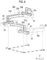
- Fig. 5 a part, that is, the flow channel units 20b to 20e of the three-dimensional flow channel 4 shown in Fig. 2 are taken out and shown.
- the flow directions of the fluids in the respective flow channel units 20b to 20e intersect each other at an angle of 90 degrees.
- the direction of a center line Of which connects the center of the inflow port 21 and the center of the outflow port 22 and is parallel to the plane of Fig. 4 is set to be the flow direction of the fluid.
- all the flow directions of the fluids in the respective flow channel units 20b to 20e connected to each other are orthogonal to each other. That is, the center lines Of of the flow channel units 20 connected to each other are orthogonal to each other.
- the flow direction (the direction of the center line Of) in the flow channel unit 20b is an X direction in an X-Y-Z orthogonal coordinate, and the flow direction in the flow channel unit 20c is a Y direction.
- the flow direction in the flow channel unit 20d is the X direction and is a direction opposite to the flow direction in the flow channel unit 20b.
- the flow direction in the flow channel unit 20e is the Y direction and is a direction opposite to the flow direction in the flow channel unit 20c.
- the fluid can flow with the flow direction thereof being divided vertically, and the flow of the fluid can be repeated while changing a direction. In this way, it is possible to greatly improve the mixing efficiency of a plurality of fluids. Further, as shown in Fig. 5 , it is possible to form a flow that makes one revolution in the fluid mixing device 1, and therefore, it is possible to reduce the installation area of the entire flow channel.
- the inflow port 21 of the flow channel unit 20b located in the first layer is directed downward and is connected to the outflow port 22 of the flow channel unit 20a located in the second layer.
- the outflow port 22 of the flow channel unit 20b is directed downward and is connected to the inflow port 21 of the flow channel unit 20c of the second layer.
- the outflow port 22 of the flow channel unit 20c of the second layer is directed downward and is connected to the inflow port 21 of the flow channel unit 20d of the third layer.
- the outflow port 22 of the flow channel unit 20d is directed downward and is connected to the inflow port 21 of the flow channel unit 20e of the fourth layer.
- the outflow port 22 of the flow channel unit 20e is directed upward and is connected to the inflow port 21 of the flow channel unit 20f located in the third layer. Then, the outflow port 22 of the flow channel unit 20f is connected to the inflow port 21 of the flow channel unit 20g located in the fourth layer.
- the flow directions (the directions of the center lines Of) in the connected fluid units are orthogonal to each other.
- fluid inlet 2 communicates with the inflow path 21 of the flow channel unit 20a
- fluid outlet 3 communicates with the outflow port 22 of the flow channel unit 20g.
- Fig. 6 is for describing the flow of the fluid when it passes through the flow channel units 20c, 20d, and 20e shown in Fig. 5 .
- the fluid changes a direction and flows into the inflow port 21 of the flow channel unit 20c from the Z direction
- the fluid is divided into two fluid flows by the branch flow channels 23 (the first flow channels 23a and 23b) of the flow channel unit 20c, thereby flowing in the directions opposite to each other in the X direction, and thereafter, the split fluids turn so as to pass through the second flow channels 23c and 23d and join together in the Y direction, and the joined fluid is led to the outflow port 22.
- the fluid changes the flow direction by 90 degrees, flows into the inflow port 21 of the flow channel unit 20d from the Z direction, and is divided into two fluid flows by the branch flow channels 23 of the flow channel unit 20d, thereby flowing in the directions opposite to each other in the Y direction, and thereafter, the split fluids turn and join together in the X direction, and the joined fluid is led to the outflow port 22.
- the fluid changes the flow direction by 90 degrees, flows into the inflow port 21 of the flow channel unit 20e from the Z direction, and is divided into two fluid flows by the branch flow channels 23 of the flow channel unit 20e, thereby flowing in the directions opposite to each other in the X direction, and thereafter, the split fluids turn and join together in the Y direction, and the joined fluid is led to the outflow port 22.
- the direction (the X direction) in which the flow of the inflow fluid is divided in the flow channel unit 20c, the direction (the Y direction) in which the flow of the inflow fluid is divided in the next flow channel unit 20d, and the direction (the X direction) in which the flow of the inflow fluid is divided in the next flow channel unit 20e are always directions intersecting each other, preferably, directions orthogonal to each other, and therefore, it is possible to greatly improve the mixing efficiency of the fluid.
- the three-dimensional flow channel 4 as shown in Fig. 2 may be configured by making each of the flow channel units 20a to 20g with a pipe and connecting them.
- the respective layers are configured with a plurality of flow channel plates and the flow channel unit is configured of a groove formed in each flow channel plate.
- the three-dimensional flow channel 4 is configured by stacking flow channel plates 11 to 14 in which each of the flow channel units 20a to 20g is formed by a groove.
- Fig. 7 is an exploded perspective view of the fluid mixing device 1 according to this embodiment.
- Fig. 8 is a perspective view showing the configuration of the second flow channel plate 12 from the top shown in Fig. 7
- Fig. 9 is a bottom view thereof.
- the fluid mixing device 1 is configured by stacking the flow channel plates 11 to 14 configuring the first to fourth layers from the top and a base plate 15.
- the fluid inlet 2 and the flow channel unit 20b are formed in the flow channel plate 11.
- the flow channel units 20a and 20c are formed in the flow channel plate 12.
- the flow channel units 20d and 20f are formed in the flow channel plate 13.
- the flow channel units 20e and 20g are formed in the flow channel plate 14.
- the fluid outlet 3 is formed in the base plate 15.
- Each of the flow channel units 20a to 20g is formed between a groove formed on the lower side of each of the flow channel plates 11 to 14 and a flat surface of an adjacent flow channel plate or the base plate which is in close contact with each flow channel plate so as to cover the groove.
- a connection flow channel connecting the inflow port 21 and the outflow port 22 of each flow channel unit is configured with a through-hole which is formed on the upper side of each of the flow channel plates 11 to 14 to penetrate each flow channel plate.
- the grooves for the flow channel units 20a and 20c are formed on the lower side thereof and connection flow channels 24 and 25 which are connected to the inflow port 21 and the outflow port 22 of the flow channel unit 20a are formed on the upper side thereof.
- the flow channel units 20a to 20g are connected as shown by the arrows in Fig. 7 , whereby the three-dimensional flow channel 4 is configured.
- the fluid mixing device 1 by forming the respective flow channel units 20a to 20g in the flow channel plates 11 to 14 configuring the respective layers, it is possible to configure the three-dimensional flow channel 4 described above. According to this, it is possible to configure the three-dimensional flow channel 4 according to this embodiment with an extremely simple configuration as compared with a case where the flow channel units 20a to 20g are configured with pipes and connected to each other.
- the two flow channel units are formed in a single flow channel plate, like the flow channel plates 12 to 14 shown in Fig. 7 , the two flow channel units are formed with the direction of a flow from the inflow port to the outflow port of each flow channel unit being reversed by 180 degrees, whereby the installation area can be reduced. In this manner, the installation area can be reduced as the number of flow channel units which are formed in a single flow channel plate is increased or the density thereof is increased.
- the respective flow channel units 20a and 20c of the flow channel plate 12 are disposed in the same direction as the respective flow channel units 20e and 20g of the flow channel plate 14, and therefore, the same flow channel plate can be used for the flow channel plates 12 and 14.
- the flow channel pattern shown in Fig. 5 can be increased with a simple configuration in which the same flow channel plates as the flow channel plates 13 and 14 are alternately laminated in this order further toward the lower side than the flow channel plate 14.
- the mixing efficiency increases as the number of flow channel patterns increases. Therefore, it is possible to more easily increase the mixing efficiency.
- each of the flow channel units 20a to 20g is not limited to the shape shown in Fig. 4 .
- the branch flow channel 23 may be configured with a curved line, as shown in Fig. 10.
- Fig. 10 is an example in which each of the second flow channels 23c and 23d is configured with a curved line.
- each of the first flow channels 23a and 23b may be configured with a curved line.
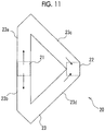
- a case where the joining flow channel 23e is connected to the second flow channels 23c and 23d is given as an example.
- the joining flow channel may be eliminated, as shown in Fig. 11.
- FIG. 11 shows a case where the outflow port 22 is formed at a joining portion of the second flow channels 23c and 23d. Also in the three-dimensional flow channels configured of the flow channel units 20a to 20g having the basic shapes shown in Figs. 10 and 11 , it is possible to exhibit the same effect as that in the three-dimensional flow channel 4 by the flow channel units 20a to 20g each having the basic shape shown in Fig. 4 .
- the fluid mixing device 1 by disposing the plurality of flow channel units 20a to 20g in a plurality of layers and disposing the flow channel units 20a to 20g such that the flow directions in the respective flow channel units 20a to 20g intersect each other between the respective layers, it is possible to divide the laminar flow flowing through each of the flow channel units 20a to 20g perpendicularly to the boundary surface therebetween, and it is possible to repeat this. In this way, it is possible to greatly improve the mixing rate of the fluid.
- the three-dimensional flow channel 4 shown in Fig. 2 in this embodiment can also be used upside down. In this case, the flow direction of the fluid shown in Fig. 4 is reversed. Even in this way, the flow directions in the respective flow channel units are disposed so as to intersect each other between the respective layers, and therefore, it is possible to divide the laminar flow flowing in the flow channel unit perpendicularly to the boundary surface, and it is possible to repeat this. In this way, similar to the case of the three-dimensional flow channel 4 shown in Fig. 2 , it is possible to greatly improve the mixing rate of the fluid.
- the present invention is applied to a fluid mixing device that mixes a sample of human body ingesta or the like with a reagent.
- a fluid mixing device that mixes a sample of human body ingesta or the like with a reagent
- the present invention can be applied to various fluid mixing devices that mix a plurality of fluids.
- the present invention may be applied to a fluid mixing device that mixes liquid fuel with water.
Landscapes
- Chemical & Material Sciences (AREA)
- Chemical Kinetics & Catalysis (AREA)
- Dispersion Chemistry (AREA)
- Health & Medical Sciences (AREA)
- Analytical Chemistry (AREA)
- General Health & Medical Sciences (AREA)
- Hematology (AREA)
- Clinical Laboratory Science (AREA)
- Physical Or Chemical Processes And Apparatus (AREA)
Applications Claiming Priority (2)
| Application Number | Priority Date | Filing Date | Title |
|---|---|---|---|
| JP2014210246 | 2014-10-14 | ||
| PCT/JP2015/073482 WO2016059874A1 (fr) | 2014-10-14 | 2015-08-21 | Dispositif de mélange de fluides |
Publications (2)
| Publication Number | Publication Date |
|---|---|
| EP3207980A1 true EP3207980A1 (fr) | 2017-08-23 |
| EP3207980A4 EP3207980A4 (fr) | 2018-07-04 |
Family
ID=55746422
Family Applications (1)
| Application Number | Title | Priority Date | Filing Date |
|---|---|---|---|
| EP15851470.3A Withdrawn EP3207980A4 (fr) | 2014-10-14 | 2015-08-21 | Dispositif de mélange de fluides |
Country Status (4)
| Country | Link |
|---|---|
| US (1) | US20170216796A1 (fr) |
| EP (1) | EP3207980A4 (fr) |
| JP (1) | JP6346298B2 (fr) |
| WO (1) | WO2016059874A1 (fr) |
Families Citing this family (15)
| Publication number | Priority date | Publication date | Assignee | Title |
|---|---|---|---|---|
| US11035480B2 (en) * | 2016-02-24 | 2021-06-15 | Leanna Levine and Aline, Inc. | Mechanically driven sequencing manifold |
| US10662527B2 (en) * | 2016-06-01 | 2020-05-26 | Asm Ip Holding B.V. | Manifolds for uniform vapor deposition |
| CN109464973B (zh) * | 2018-12-19 | 2024-03-08 | 上海璨谊生物科技有限公司 | 微通道模块 |
| US12516414B2 (en) | 2019-03-19 | 2026-01-06 | Asm Ip Holding B.V. | Reactor manifolds |
| US11492701B2 (en) | 2019-03-19 | 2022-11-08 | Asm Ip Holding B.V. | Reactor manifolds |
| KR20210048408A (ko) | 2019-10-22 | 2021-05-03 | 에이에스엠 아이피 홀딩 비.브이. | 반도체 증착 반응기 매니폴드 |
| CN115698702A (zh) * | 2020-05-22 | 2023-02-03 | 沃特世科技公司 | 用于液相色谱的多样品通道装置 |
| KR102337596B1 (ko) * | 2020-08-14 | 2021-12-09 | 주식회사 지앤아이솔루션 | 연속 유동 반응기 |
| CN111957279B (zh) * | 2020-09-17 | 2025-04-22 | 杭州沈氏节能科技股份有限公司 | 微通道结构、具有其的微通道反应组件和微通道反应器 |
| JP7716883B2 (ja) * | 2021-05-13 | 2025-08-01 | 株式会社神鋼環境ソリューション | 流路装置 |
| CN114534652B (zh) * | 2022-02-08 | 2024-07-19 | 上海天泽云泰生物医药有限公司 | 波形微结构混合单元及其用途 |
| CN114505025B (zh) * | 2022-02-16 | 2023-07-18 | 安徽科芯微流化工科技有限公司 | 一种高效微通道反应器 |
| KR102520181B1 (ko) * | 2022-06-09 | 2023-04-10 | 주식회사 지앤아이솔루션 | 연속 흐름 반응기 |
| US12599879B2 (en) * | 2023-06-14 | 2026-04-14 | Micronox Inc. | Nano cell block module for homogenizing a solution with a high pressure |
| CN118403541A (zh) * | 2024-05-20 | 2024-07-30 | 深圳市纬博生物科技有限公司 | 一种混合单元、微流控芯片和混合系统 |
Family Cites Families (8)
| Publication number | Priority date | Publication date | Assignee | Title |
|---|---|---|---|---|
| JP3638151B2 (ja) * | 1996-03-28 | 2005-04-13 | メルク パテント ゲゼルシャフト ミット ベシュレンクテル ハフトング | 少量液体の混合デバイス |
| EP1309404A2 (fr) * | 2000-08-07 | 2003-05-14 | Nanostream, Inc. | Melangeur fluidique pour systeme microfluidique |
| JP3694877B2 (ja) * | 2001-05-28 | 2005-09-14 | 株式会社山武 | マイクロ混合器 |
| JP3810778B2 (ja) * | 2004-07-02 | 2006-08-16 | 雄志 平田 | 平板静止型混合器 |
| JP2006346671A (ja) * | 2005-05-16 | 2006-12-28 | Dainippon Screen Mfg Co Ltd | 液液界面反応装置 |
| US7718420B2 (en) * | 2006-10-10 | 2010-05-18 | Postech Academy-Industry Foundation | Microfluidic biochip for blood typing based on agglutination reaction |
| EP2431090A4 (fr) * | 2009-05-14 | 2014-04-02 | Hitachi Plant Technologies Ltd | Système de microréacteur |
| WO2013111789A1 (fr) * | 2012-01-23 | 2013-08-01 | 旭有機材工業株式会社 | Mélangeur statique et dispositif utilisant le mélangeur statique |
-
2015
- 2015-08-21 EP EP15851470.3A patent/EP3207980A4/fr not_active Withdrawn
- 2015-08-21 WO PCT/JP2015/073482 patent/WO2016059874A1/fr not_active Ceased
- 2015-08-21 JP JP2016554002A patent/JP6346298B2/ja not_active Expired - Fee Related
-
2017
- 2017-04-13 US US15/486,359 patent/US20170216796A1/en not_active Abandoned
Also Published As
| Publication number | Publication date |
|---|---|
| JP6346298B2 (ja) | 2018-06-20 |
| JPWO2016059874A1 (ja) | 2017-07-20 |
| WO2016059874A1 (fr) | 2016-04-21 |
| US20170216796A1 (en) | 2017-08-03 |
| EP3207980A4 (fr) | 2018-07-04 |
Similar Documents
| Publication | Publication Date | Title |
|---|---|---|
| EP3207980A1 (fr) | Dispositif de mélange de fluides | |
| JP3694877B2 (ja) | マイクロ混合器 | |
| CN105664773B (zh) | 平面被动式微混合器 | |
| CN105056821B (zh) | 一种对称椭圆弧挡板的十字微混合器 | |
| CN201959734U (zh) | 非对称分离重组扇形空腔结构微混合器 | |
| JP3810778B2 (ja) | 平板静止型混合器 | |
| JP2006346671A (ja) | 液液界面反応装置 | |
| JP5642488B2 (ja) | 流路構造体 | |
| CN113198403A (zh) | 一种微通道反应器 | |
| CN105771765B (zh) | 一种内置周期性阻块和挡板的被动式微混合器 | |
| JP2006102681A (ja) | 流体混合器及びマイクロリアクタシステム | |
| CN212328253U (zh) | 微通道反应及混合装置 | |
| CN106334505B (zh) | 一种多相流混合反应通道及微反应器 | |
| CN111715161B (zh) | 微通道反应及混合装置 | |
| JP6046465B2 (ja) | 静止型流体混合装置 | |
| JP3694878B2 (ja) | マイクロ混合器 | |
| CN214159656U (zh) | 一种基于迪恩涡二次流混合通道的微流控浓度梯度芯片 | |
| CN215783445U (zh) | 微流控混合芯片、混合装置与生物检测系统 | |
| CN110975776A (zh) | 一种微流体混料通道、微流控制装置及微反应器 | |
| CN110404490A (zh) | 一种分层混合微反应器 | |
| CN113649093A (zh) | 微流控混合芯片、混合装置与生物检测系统 | |
| JP5794884B2 (ja) | 流体制御システム | |
| JP2012120962A (ja) | 流路構造体 | |
| JP4478932B2 (ja) | マイクロ混合器 | |
| JP7813206B2 (ja) | 流体混合器 |
Legal Events
| Date | Code | Title | Description |
|---|---|---|---|
| PUAI | Public reference made under article 153(3) epc to a published international application that has entered the european phase |
Free format text: ORIGINAL CODE: 0009012 |
|
| 17P | Request for examination filed |
Effective date: 20170411 |
|
| AK | Designated contracting states |
Kind code of ref document: A1 Designated state(s): AL AT BE BG CH CY CZ DE DK EE ES FI FR GB GR HR HU IE IS IT LI LT LU LV MC MK MT NL NO PL PT RO RS SE SI SK SM TR |
|
| AX | Request for extension of the european patent |
Extension state: BA ME |
|
| DAV | Request for validation of the european patent (deleted) | ||
| DAX | Request for extension of the european patent (deleted) | ||
| A4 | Supplementary search report drawn up and despatched |
Effective date: 20180605 |
|
| RIC1 | Information provided on ipc code assigned before grant |
Ipc: B01F 5/06 20060101ALI20180529BHEP Ipc: B01F 5/00 20060101AFI20180529BHEP Ipc: B01F 13/00 20060101ALI20180529BHEP Ipc: B01L 3/00 20060101ALI20180529BHEP |
|
| RAP1 | Party data changed (applicant data changed or rights of an application transferred) |
Owner name: ALPS ALPINE CO., LTD. |
|
| STAA | Information on the status of an ep patent application or granted ep patent |
Free format text: STATUS: THE APPLICATION HAS BEEN WITHDRAWN |
|
| 18W | Application withdrawn |
Effective date: 20200304 |