EP3208014A1 - Vorrichtung, verfahren und programm zur erkennung einer geschmolzenen metalloberfläche in einer stranggussform - Google Patents
Vorrichtung, verfahren und programm zur erkennung einer geschmolzenen metalloberfläche in einer stranggussform Download PDFInfo
- Publication number
- EP3208014A1 EP3208014A1 EP15851433.1A EP15851433A EP3208014A1 EP 3208014 A1 EP3208014 A1 EP 3208014A1 EP 15851433 A EP15851433 A EP 15851433A EP 3208014 A1 EP3208014 A1 EP 3208014A1
- Authority
- EP
- European Patent Office
- Prior art keywords
- continuous casting
- casting mold
- molten metal
- metal surface
- surface level
- Prior art date
- Legal status (The legal status is an assumption and is not a legal conclusion. Google has not performed a legal analysis and makes no representation as to the accuracy of the status listed.)
- Granted
Links
Images


Classifications
-
- B—PERFORMING OPERATIONS; TRANSPORTING
- B22—CASTING; POWDER METALLURGY
- B22D—CASTING OF METALS; CASTING OF OTHER SUBSTANCES BY THE SAME PROCESSES OR DEVICES
- B22D11/00—Continuous casting of metals, i.e. casting in indefinite lengths
- B22D11/16—Controlling or regulating processes or operations
- B22D11/18—Controlling or regulating processes or operations for pouring
- B22D11/181—Controlling or regulating processes or operations for pouring responsive to molten metal level or slag level
- B22D11/182—Controlling or regulating processes or operations for pouring responsive to molten metal level or slag level by measuring temperature
-
- B—PERFORMING OPERATIONS; TRANSPORTING
- B22—CASTING; POWDER METALLURGY
- B22D—CASTING OF METALS; CASTING OF OTHER SUBSTANCES BY THE SAME PROCESSES OR DEVICES
- B22D11/00—Continuous casting of metals, i.e. casting in indefinite lengths
- B22D11/04—Continuous casting of metals, i.e. casting in indefinite lengths into open-ended moulds
- B22D11/041—Continuous casting of metals, i.e. casting in indefinite lengths into open-ended moulds for vertical casting
-
- G—PHYSICS
- G01—MEASURING; TESTING
- G01F—MEASURING VOLUME, VOLUME FLOW, MASS FLOW OR LIQUID LEVEL; METERING BY VOLUME
- G01F23/00—Indicating or measuring liquid level or level of fluent solid material, e.g. indicating in terms of volume or indicating by means of an alarm
- G01F23/22—Indicating or measuring liquid level or level of fluent solid material, e.g. indicating in terms of volume or indicating by means of an alarm by measuring physical variables, other than linear dimensions, pressure or weight, dependent on the level to be measured, e.g. by difference of heat transfer of steam or water
Definitions
- the present invention relates to an apparatus, a method, and a program for detecting a molten metal surface level in a continuous casting mold, and is suitably used for detecting the molten metal surface level in the continuous casting mold.
- the molten metal surface level refers to the height position of the surface of the molten steel.
- Patent Literature 1 the following technique is disclosed.
- a plurality of temperature measurement elements are embedded in the mold at regular intervals along the casting direction of the mold (the height direction of the mold).
- the time change rate of the temperature at a point of each temperature measurement element is calculated to detect a temperature measurement element (n) exhibiting the maximum value of the time change rate.
- a position exhibiting the maximum value of a quadric curve linking the time change rate of the temperature measurement element (n) and the time change rates of two temperature measurement elements (n - 1), (n + 1) adjacent to the temperature measurement element (n) is obtained, and the position is regarded as the molten metal surface level.
- thermocouples are embedded in the mold at intervals along the casting direction of the mold (the height direction of the mold). For detecting the molten metal surface level, giving an initial temperature distribution and deciding a temporary molten metal surface level (division position) are performed first. Upon decision of the temporary molten metal surface level, the maximum heat flux and the minimum heat flux at the temporary molten metal surface level are calculated by analysis of heat conduction inverse problems using the temperature changes measured by the thermocouples. The maximum heat flux and the minimum heat flux at the temporary molten metal surface level are calculated with the temporary molten metal surface level changed. Among the calculated positions of the temporary molten metal surface levels, the temporary molten metal surface level where the difference between the maximum heat flux and the minimum heat flux defined by performing experiments in advance is smallest is regarded as the actual molten metal surface level.
- Patent Literature 1 is based on the empirical rule that the position where the temperature in the casting direction of the mold is maximum exists near the molten metal surface, and this position is in a certain correlation with the molten metal surface level. In the case based on the empirical rule as described above, the detection accuracy of the molten metal surface level may decrease.
- the initial value (initial condition) of the temperature distribution is necessary when performing the analysis of heat conduction inverse problems by the non-stationary heat conduction equation. Further, the heat flux in the casting direction is calculated as a discrete value. Accordingly, also in the technique described in Patent Literature 2, the detection accuracy of the molten metal surface level may decrease. In particular, when the state of the molten steel inside the mold rapidly changes to increase the temporal change of the heat flux, the detection accuracy of the molten metal surface level may decrease.
- the present invention has been made in consideration of the above points, and its object is to increase the detection accuracy of the molten metal surface level in the continuous casting mold.
- An apparatus for detecting a molten metal surface level in a continuous casting mold of the present invention includes: a temperature acquisition means which acquires temperatures measured by a plurality of temperature measurement means embedded in the continuous casting mold along a casting direction of the continuous casting mold; a heat flux derivation means which derives a value of a casting direction component of a heat flux vector on an inner wall surface of the continuous casting mold, based on a result of performing analysis of non-stationary heat conduction inverse problems from the temperatures derived by the temperature acquisition means; and a molten metal surface level derivation means which derives a molten metal surface level inside the continuous casting mold, based on the value of the casting direction component of the heat flux vector on the inner wall surface of the continuous casting mold derived by the heat flux derivation means, wherein the molten metal surface level derivation means derives, as the molten metal surface level, a position where an absolute value of the value of the casting direction component of the heat flux vector whose vector of the casting direction component is in a direction opposite
- a method for detecting a molten metal surface level in a continuous casting mold of the present invention includes: a temperature acquisition step of acquiring temperatures measured by a plurality of temperature measurement steps embedded in the continuous casting mold along a casting direction of the continuous casting mold; a heat flux derivation step of deriving a value of a casting direction component of a heat flux vector on an inner wall surface of the continuous casting mold, based on a result of performing analysis of non-stationary heat conduction inverse problems from the temperatures derived by the temperature acquisition step; and a molten metal surface level derivation step of deriving a molten metal surface level inside the continuous casting mold, based on the value of the casting direction component of the heat flux vector on the inner wall surface of the continuous casting mold derived by the heat flux derivation step, wherein the molten metal surface level derivation step derives, as the molten metal surface level, a position where an absolute value of the value of the casting direction component of the heat flux vector whose vector of the casting direction component is in a
- a program of the present invention causes a computer to execute: a temperature acquisition step of acquiring temperatures measured by a plurality of temperature measurement steps embedded in a continuous casting mold along a casting direction of the continuous casting mold; a heat flux derivation step of deriving a value of a casting direction component of a heat flux vector on an inner wall surface of the continuous casting mold, based on a result of performing analysis of non-stationary heat conduction inverse problems from the temperatures derived by the temperature acquisition step; and a molten metal surface level derivation step of deriving a molten metal surface level inside the continuous casting mold, based on the value of the casting direction component of the heat flux vector on the inner wall surface of the continuous casting mold derived by the heat flux derivation step, wherein the molten metal surface level derivation step derives, as the molten metal surface level, a position where an absolute value of the value of the casting direction component of the heat flux vector whose vector of the casting direction component is in a direction opposite to the casting direction is maximum.
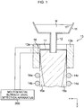
- Fig. 1 is a view illustrating an example of a configuration of a system for detecting a molten metal surface level in a continuous casting mold.
- Fig. 1 illustrates a cross section of a continuous casting machine obtained by cutting it along its height direction (a y-axis direction).
- the continuous casting machine has a tundish 11, an immersion nozzle 12, a mold 13, and pinch rolls 14a to 14d.
- the continuous casting machine can be realized by a publicly-known technique. Accordingly, the detailed description of the continuous casting machine will be omitted here.
- the tundish 11 temporarily stores molten metal M supplied from a ladle.
- the mold 13 is disposed below the tundish 11 with a gap intervening between the mold 13 and the tundish 11.
- the mold 13 has, for example, two short side parts 13a, 13b, and two long side parts.
- the two short side parts 13a, 13b are arranged with a gap intervening between them to be opposed to each other in a width direction (an x-axis direction).
- the two long side parts are arranged with a gap intervening between them to be opposed to each other in a depth direction (a direction perpendicular to an x-axis and a y-axis).
- a region surrounded by the two long side parts and the two short side parts 13a, 13b becomes a region in a hollow rectangular parallelepiped shape. This region becomes a region inside the mold 13.
- a groove is formed on an outer wall surface of the mold 13.
- the mold 13 is water-cooled by running water through the groove. Note that only the short side parts of the long side parts and the short side parts are illustrated in Fig. 1 for
- the immersion nozzle 12 injects the molten metal M stored in the tundish 11 to the inside of the mold 13.
- the immersion nozzle 12 is disposed such that its base end is located at the bottom surface of the tundish 11 and a predetermined region on the tip end side is located inside the mold 13. Further, the inside of the immersion nozzle 12 and the inside of the tundish 11 are communicated with each other. Note that the supply amount of the molten metal M to be supplied from the tundish 11 to the immersion nozzle 12 is adjusted by a sliding nozzle or a stopper.
- a plurality of pairs of pinch rolls 14a to 14d are arranged along a conveyance path for steel drawn downward from the mold 13. Note that only two pairs of pinch rolls 14a to 14d are illustrated in Fig. 1 . However, more pinch rolls are actually arranged according to the length of the conveyance path. Outside the pinch rolls 14a to 14d, a plurality of cooling sprays are arranged. The plurality of cooling sprays spray cooling water for cooling the steel drawn downward from the mold 13, to the steel.
- the molten metal injected to the inside of the mold 13 is cooled by the mold 13 and solidified due to formation of solidified shells 15a, 15b from its surface.
- the steel having a surface being the solidified shells 15a, 15b and an inside being not solidified is continuously drawn from a lower end portion of the mold 13 while being sandwiched between the pinch rolls 14a to 14d.
- the cooling water sprayed from the cooling sprays proceeds cooling of the steel to solidify the steel up to the inside.
- the thus-solidified steel is cut into a predetermined size on the downstream side of the continuous casting machine, whereby a cast slab different in shape of the cross section such as slab, bloom, billet or the like is manufactured.
- powder 17 is added as needed to the molten metal inside the mold 13.
- a thin film of the powder 17 exists also between an inner wall surface of the mold 13 and the solidified shells 15a, 15b as well as on the surface of the molten metal inside the mold 13.
- the addition of the powder 17 in this manner achieves retention of heat of the molten metal, prevention of oxidation of the molten metal, absorption of inclusion in the molten metal, securement of lubricity of the solidified shells 15a, 15b, and adjustment of removal of heat of the molten metal.
- Uniform generation of the solidified shells 15a, 15b near the meniscus in the mold 13 in the above manner prevents surface crack of the solidified shells 15a, 15b and prevents seizing between the mold 13 and the solidified shells 15a, 15b.
- thermocouples 18 are embedded along the casting direction (the y-axis direction).
- the number of the plurality of thermocouples 18 is preferably three or more. According to the calculation accuracy of a later-described heat flux, the number of the plurality of thermocouples 18 and the interval between two adjacent thermocouples 18 can be decided. Further, in the example illustrated in Fig. 1 , the plurality of thermocouples 18 are embedded in a region relatively closer to the inner wall surface of the inner wall surface and the outer wall surface of the mold 13. However, the plurality of thermocouples 18 do not always need to be embedded in such a region as long as they are embedded in the mold 13. As illustrated in Fig.
- thermocouples 18 are embedded in the short side part 13a
- a plurality of thermocouples may be embedded in at least any one of the short side part 13b and the two long side parts in addition to or instead of the short side part 13a.
- the inner wall surface of the mold 13 is called an operation surface, and the outer wall surface thereof is called a water cooled surface.
- the surface in contact with the molten metal of the surfaces of the mold 13 is the operation surface.
- the surface in contact with the powder 17 of the surfaces of the mold 13 is the operation surface.
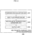
- Fig. 2 is a diagram illustrating an example of a functional configuration of the apparatus 200 for detecting the molten metal surface level in the continuous casting mold.
- the apparatus for detecting the molten metal surface level in the continuous casting mold is abbreviated as a molten metal surface level detection apparatus as needed.
- the molten metal surface level detection apparatus 200 performs analysis of non-stationary heat conduction inverse problems using the temperatures measured by the plurality of thermocouples 18.
- the non-stationary heat conduction inverse problems here refer to a problem of estimating a boundary condition or an initial condition such as the temperature and the heat flux in a boundary region with the temperature information inside the region having been known, based on the non-stationary heat conduction equation dominating a calculation area.
- non-stationary heat conduction forward problems refer to a problem of estimating the temperature information inside the region, based on a known boundary condition.
- the molten metal surface level detection apparatus 200 calculates the value of a component in the y-axis direction (the casting direction of the mold 13) of a heat flux vector on the inner wall surface of the mold 13 using an interpolation/extrapolation temperature function obtained by performing the analysis of non-stationary heat conduction inverse problems.
- the interpolation/extrapolation temperature function is a function indicating the temperature of the mold 13 at a position (x, y) and a time t.
- the molten metal surface level detection apparatus 200 detects a molten metal surface level, based on the value of a y-axis direction component of the heat flux vector on the inner wall surface of the mold 13.
- the molten metal surface level is the height position (a position in the y-axis direction) of the surface of the molten metal inside the mold 13.
- the role of the mold 13 is cooling and solidification of the molten metal. Therefore, in discussing the detection of the molten metal surface level by performing the analysis of non-stationary heat conduction inverse problems, the behavior of the heat flux in an x-axis direction (a heat removal direction of the mold 13) has attracted attention, whereas the behavior of the heat flux in the y-axis direction (the casting direction of the mold 13) has not attracted attention. Further, the value of the y-axis direction component of the heat flux vector is smaller than the value of an x-axis direction component.
- the present inventors have reached an idea of detecting the molten metal surface level, based on the inference that "on the molten metal surface inside the mold 13, the magnitude of the vector in a direction opposite (namely, facing the normal direction to the molten metal surface) to the casting direction of the vector of the y-axis direction component of the heat flux vector becomes large as compared with that at the other portion of the mold 13 due to the influence of the heat removal by the powder 17" because the powder 17 is supplied onto the molten metal surface inside the mold 13.
- the molten metal surface level detection apparatus 200 in this embodiment has been realized.
- an example of a concrete configuration of the molten metal surface level detection apparatus 200 in this embodiment will be described.
- the molten metal surface level detection apparatus 200 has a temperature acquisition unit 201, a heat flux derivation unit 202, a heat flux derivation unit 202, and a molten metal surface level derivation unit 203.
- the temperature acquisition unit 201 receives input of temperatures [K] measured by the plurality of thermocouples 18, and outputs the temperatures measured at the same time by the plurality of thermocouples 18.
- the temperature acquisition unit 201 performs such output of the temperatures at each predetermined sampling time. For example, the temperature acquisition unit 201 receives input of and outputs the temperatures measured by the plurality of thermocouples 18 every time the sampling time elapses.
- an interpolation/extrapolation temperature function u ⁇ (x, y, t) for estimating the temperature of the mold 13 is used to make a mathematical expression of predicting the temporal change in temperature distribution on a two-dimensional cross section in the casting direction (the y-axis direction)-the heat removal direction (the x-axis direction) of the mold 13.
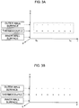
- Fig. 3A is a chart illustrating an example of a coordinate system of the non-stationary heat conduction inverse problems.
- Fig. 3A illustrates a definition point of the information amount on the two-dimensional cross section of a space x-time t at a certain position in the y-axis direction.
- Fig. 3B is also a chart illustrating an example of the coordinate system of the non-stationary heat conduction inverse problems.
- Fig. 3B illustrates a definition point of the information amount on the two-dimensional cross section of a space x-space y at a certain time t.
- Fig. 3A and Fig. 3B illustrate the two-dimensional cross sections of the same three-dimensional coordinates (coordinates of a space x-space y-time t).
- the x-axis and the y-axis are space axes.
- the t-axis is a time axis.
- plots indicated by black circles are definition points of the information amounts, respectively.
- the definition point of the information amount indicates the position of the thermocouple 18 and the time when the temperature was measured by the thermocouple 18.
- the information amount at the definition point includes the temperature measured by the thermocouple 18.
- Plots indicated by broken lines are also definition points of the information amounts, respectively.
- the definition point of the information amount indicates the position on the outer wall surface of the mold 13 and the time when the heat flux on the outer wall surface is estimated.
- a temperature measurement means such as the thermocouple is not provided on the outer wall surface of the mold 13 will be described as an example.
- the information amount at the definition point is regarded as the heat flux decided with a heat transfer coefficient ⁇ between the material constituting the mold 13 and water and a water temperature u w having been known.
- each of the points on the three-dimensional coordinates of the x-axis-the y-axis-the t-axis represented by the plots indicated by the black circles and the plots indicated by the broken lines illustrated in Fig. 3A and the plots indicated by the black circles and the plots indicated by the broken lines illustrated in Fig. 3B is the definition point of the information amount.
- a timing t N is a timing when the latest temperatures were measured by the plurality of thermocouples 18.
- seven temperature measurement timings (seven timings such as timings to to t N ) are employed in sequence from the new one as a time t when the definition point of the information amount is decided will be described as an example. More specifically, when the temperatures measured by the plurality of thermocouples 18 are newly acquired, the heat flux derivation unit 202 excludes the definition point of the information amount including the oldest temperature measurement timing of the seven temperature measurement timings, from the seven definition points of the information amounts. The heat flux derivation unit 202 then adds the definition point of the information amount including the latest temperature measurement timing to the seven definition points of the information amounts. Note that the number of times t deciding the definition points of the information amounts is not limited to seven.
- thermocouples 18 are arranged at regular intervals along the y-axis direction as the plurality of thermocouples 18 will be illustrated as an example.
- the interval between two thermocouples 18 adjacent to each other does not need to be the regular interval.
- the number of the plurality of thermocouples 18 is not limited to seven.
- the heat flux derivation unit 202 derives a weight vector ⁇ j included in the interpolation/extrapolation temperature function u ⁇ (x, y, t) on the basis of the above definition points of the information amounts.
- a is a square root of the thermal diffusion coefficient [m 2 /s] of the material constituting the mold.
- 0 ⁇ x ⁇ 1 and 0 ⁇ y ⁇ 1 indicate that the coordinates (x, y) on the x-axis and the y-axis are standardized by [0, 1]. More specifically, each coordinate on the x-axis is decided so that the coordinate on the x-axis on the inner wall surface of the mold 13 is "0" and the coordinate on the x-axis on the outer wall surface thereof is "1". Further, each coordinate on the y-axis is decided so that the coordinate on the y-axis at the upper end of the mold 13 is "0" and the coordinate on the y-axis at the lower end thereof is "1".
- ⁇ is a heat conductivity [W/mk] of the material constituting the mold 13.
- Each of the water temperature u w , the heat transfer coefficient ⁇ between the material constituting the mold 13 and water, and the heat conductivity ⁇ of the material constituting the mold 13 is a value set in advance.
- the water temperature u w for example, an average value in a predetermined time can be used.
- the (2) expression is an expression expressing the balance between the heat fluxes on the outer wall surface of the mold 13. More specifically, the (2) expression is an expression expressing that following fist heat flux and second heat flux are equal.
- the first heat flux is a heat flux based on the temperature gradient in the heat removal direction of the mold 13 on the outer wall surface of the mold 13 and on the heat conductivity ⁇ of the material constituting the mold 13.
- the second heat flux is a heat flux based on the difference between a temperature u (1, y, t) on the outer wall surface of the mold 13 and the water temperature u w and on the heat transfer coefficient ⁇ between the material constituting the mold 13 and water.
- thermocouple temperature function u(x*, y*, t) is a function indicating the temperature measured by the thermocouple 18, and is a function of the position (x, y) of the thermocouple 18 and the time t.
- h(t) is the temperature at the time t measured by the thermocouple 18.
- x*, ⁇ [0, 1] and y* ⁇ [0, 1] indicate that the coordinates (x*, y*) on the x-axis and the y-axis of the thermocouple 18 are standardized by [0, 1]. More specifically, the x-axis of the thermocouple 18 is decided so that the coordinate on the x-axis on the inner wall surface of the mold 13 is "0" and the coordinate on the x-axis on the outer wall surface thereof is "1". Further, the y-axis of the thermocouple 18 is decided so that the coordinate on the y-axis at the upper end of the mold 13 is "0" and the coordinate on the y-axis at the lower end thereof is "1".
- the interpolation/extrapolation temperature function u ⁇ (x, y, t) is a temperature satisfying the quadratic non-stationary heat conduction equation expressed by the (1) expression, and is an approximate solution of the temperature u.
- x j and y j are elements (the coordinate on the x-axis and the coordinate on the y-axis) of an arbitrary reference position vector (x j , y j ).
- t j is an arbitrary reference time.
- a point on the three-dimensional coordinates decided by the reference position vector (x j , y j ) and the reference time t j is called a center point.
- the reference position vector (x j , y j ) and the reference time t j are made coincident with the above-described definition point of the information amount, and this also applies to this embodiment.
- the reference position vector (x j , y j ) and the reference time t j do not have to be made coincident with the above-described definition point of the information amount.
- j is a variable that identifies the above-described center point (the point on the three-dimensional coordinates decided by the reference position vector (x j , y j ) and the reference time t j ) and an integer in a range from 1 to m + l.
- n p1 ⁇ n t 1 is expressed by n p2 ⁇ n t .
- n p1 is the number of the center points j on the outer wall surface of the mold 13.
- the center point j on the outer wall surface of the mold 13 is set so that the interpolation/extrapolation temperature function u ⁇ (x, y, t) satisfies the (2) expression.
- n p2 is the position of the thermocouple 18.
- the position of the thermocouple 18 is set so that the interpolation/extrapolation temperature function u ⁇ (x, y, t) satisfies the (3) expression.
- n t is the number of times. This time is set so that the interpolation/extrapolation temperature function u ⁇ (x, y, t) satisfies the (2) expression and the (3) expression.
- m is the number of center points j decided by the positions on the outer wall surface of the mold 13 and times.
- 1 is the number of the center points j decided by the positions of the thermocouples 18 and times.
- H(t) is a Heaviside function.
- the (6) expression is an expression expressed in the form of a fundamental solution satisfying the quadratic non-stationary heat conduction equation expressed in the (1) expression.
- the fundamental solution is a solution (the temperature u) of the quadratic non-stationary heat conduction equation when the initial condition of the temperature u is expressed by a ⁇ function.
- T is a parameter for adjusting the diffusion profile of the fundamental solution of the quadratic non-stationary heat conduction equation, and is set in advance. T is a value more than 0.
- the basis function ⁇ (x-x j , y-y j , t-t j ) is a function expressed in the form of the fundamental solution satisfying the quadratic non-stationary heat conduction equation on the basis of the center point j (the reference vector (x j , y j ) and the reference time t j ).
- ⁇ j is a weight vector representing the weight of the basis function ⁇ (x-x j , y-y j , t-t j ) with respect to the interpolation/extrapolation temperature function u ⁇ (x, y, t).
- the weight vector ⁇ j is decided by the balance between the influence of the basis function ⁇ (x-x j , y-y j , t-t j ) on the interpolation/extrapolation temperature function u ⁇ (x, y, t) and the influence of another basis function ⁇ (x-x j , y-y j , t-t j ) different from the above basis function ⁇ (x-x j , y-y j , t-t j ) on the interpolation/extrapolation temperature function u ⁇ (x, y, t).
- the basis function ⁇ (x- x j , y-y j , t-t j ) exists for each center point j, and the weight vector ⁇ j also exists for each center point j.
- the interpolation/extrapolation temperature function u ⁇ (x, y, t) is expressed by the total sum of the values at respective center points j of the products of the basis function ⁇ (x- x j , y-y j , t-t j ) and the weight vector ⁇ j .
- the weight vector ⁇ j is expressed by the following (7) expression to (10) expression.
- a matrix A is a (m + l) ⁇ (m + l) matrix.
- b and ⁇ are (m + l)-dimensional column vectors. As described above, (m + l) is the number of center points j.
- g k in [] represents a k-row component of a matrix b.
- h s-m in [] represents an s-row component of the matrix b.
- m is expressed by n p1 ⁇ n t .
- n p1 is the number of the center points j on the outer wall surface of the mold 13.
- the coordinate on the x-axis is decided so that the coordinate on the x-axis on the inner wall surface of the mold 13 is "0" and the coordinate on the x-axis on the outer wall surface thereof is "1". Accordingly, in the (8) expression, x k becomes "1".
- the (7) expression to the (10) expression are expressions for deriving the weight vector ⁇ j by substituting the information on the definition point of the information amount into simultaneous equations of the (2) expression and the (4) expression and solving the simultaneous equations so as to satisfy the quadratic non-stationary heat conduction equation of the (1) expression, the boundary condition on the outer wall surface of the mold 13 of the (2) expression, the thermocouple temperature function (the temperature measured by the thermocouple in the mold 13 at each position (x*, y*) and at each time t) of the (3) expression, and the interpolation/extrapolation temperature function of the (4) expression.
- the information on the definition point of the information amount substituted into the simultaneous equations includes the position of the definition point of the information amount, the temperature by the thermocouple 18, the temperature measurement timing of the thermocouple 18, the water temperature u w , the heat conductivity ⁇ of the material constituting the mold 13, the heat transfer coefficient ⁇ between the material constituting the mold 13 and water, and the thermal diffusion coefficient a of the material constituting the mold 13.
- the water temperature u w , the heat conductivity ⁇ of the material constituting the mold 13, the heat transfer coefficient ⁇ between the material constituting the mold 13 and water, and the thermal diffusion coefficient a of the material constituting the mold 13 may be made different depending on the definition point of the information amount, or may be made the same.
- the position of the center point j is also substituted into the simultaneous equations.
- the heat flux derivation unit 202 derives the weight vector ⁇ j by the (7) expression to the (10) expression in the above manner.
- the heat flux derivation unit 202 performs the above processing every time of acquiring the temperature from the temperature acquisition unit 201.
- the value q y of the y-axis direction component of the heat flux vector is expressed by the following (11) expression.
- the heat flux derivation unit 202 derives the value q y of the y-axis direction component of the heat flux vector on the inner wall surface of the mold 13 by substituting the heat conductivity ⁇ of the material constituting the mold 13, the thermal diffusion coefficient a of the material constituting the mold 13, the reference time t j , the number m + l of the center points j, and the weight vector ⁇ j derived as described above, into the (11) expression.
- the molten metal surface level derivation unit 203 derives the relation between the value q y of the y-axis direction component of the heat flux vector and the position in the y-axis direction, from the value q y of the y-axis direction component of the heat flux vector derived by the heat flux derivation unit 202.
- the molten metal surface level derivation unit 203 derives, from the relation, the position where the value q y of the y-axis direction component of the heat flux vector has a negative value and its absolute value is maximum (namely, minimum), as the molten metal surface level.
- the y-axis is defined as illustrated in Fig. 1 .
- the position where the value q y of the y-axis direction component of the heat flux vector on the inner wall surface of the mold 13 becomes minimum is the molten metal surface level.
- the position where the value q y of the y-axis direction component of the heat flux vector on the inner wall surface of the mold 13 is maximum is the molten metal surface level.
- the molten metal surface level derivation unit 203 derives, as the molten metal surface level, the position where the absolute value of the value q y of the y-axis direction component of the heat flux vector whose y-axis component vector is in the direction opposite to the casting direction (namely, directed in the normal direction to the molten metal surface) is maximum.
- the output unit 204 outputs the information on the molten metal surface level derived by the molten metal surface level derivation unit 203.
- the output form of the information on the molten metal surface level at least one of display on a computer display, storage into a storage medium in the molten metal surface level detection apparatus 200 or a portable storage medium, and transmission to an external device can be employed.
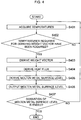
- the temperature acquisition unit 201 acquires the temperatures measured by the plurality of thermocouples 18.
- the heat flux derivation unit 202 determines whether the required number of temperatures for deriving the weight vector ⁇ j have been acquired or not. Concretely, the heat flux derivation unit 202 waits until one temperature as the number of the definition point of the information amount with respect to the thermocouple 18 is acquired. In the examples illustrated in Fig. 3A and Fig. 3B , the heat flux derivation unit 202 waits until 49 temperatures are acquired because there are seven definition points of the information amounts in the y-axis direction and there are seven definition points of the information amounts in the t-axis direction.
- the heat flux derivation unit 202 deletes the temperatures at the oldest time among the temperatures corresponding to the seven definition points of the information amounts in the y-axis direction at the same time, and adds the temperatures acquired this time.
- Step S401 the processing at Step S401 and S402 is repeatedly performed until the required number of temperatures for deriving the weight vector ⁇ j are acquired.
- the flow proceeds to Step S403.
- the heat flux derivation unit 202 derives the weight vector ⁇ j by the (7) expression to the (10) expression.
- Step S404 the heat flux derivation unit 202 derives the value q y of the y-axis direction component of the heat flux vector on the inner wall surface of the mold 13 by the (11) expression.
- the molten metal surface level derivation unit 203 derives the relation between the value q y of the y-axis direction component of the heat flux vector and the position in the y-axis direction.
- the molten metal surface level derivation unit 203 derives, from the derived relation, the position where the value q y of the y-axis direction component of the heat flux vector has a negative value and its absolute value is maximum (namely, minimum), as the molten metal surface level.
- Step S406 the output unit 204 outputs the information on the molten metal surface level derived by the molten metal surface level derivation unit 203.
- the molten metal surface level detection apparatus 200 determines whether to end the derivation of the molten metal surface level. This determination is performed, for example, based on the operation by an operator to the molten metal surface level detection apparatus 200.
- Step S401 When the derivation of the molten metal surface level is not ended as a result of the determination, the flow returns to Step S401. Then, the processing at Steps S401 to S407 is repeatedly performed every time temperatures are newly acquired at Step S401.
- Fig. 5 is a diagram illustrating an example of a hardware configuration of the molten metal surface level detection apparatus 200.
- the molten metal surface level detection apparatus 200 has a CPU (Central Processing Unit) 501, a ROM (Read Only Memory) 502, a RAM (Random Access Memory) 503, a PD (Pointing Device) 504, an HD (Hard Disk) 505, a display device 506, a speaker 507, an I/F (Interface) 508, and a system bus 509.
- CPU Central Processing Unit
- ROM Read Only Memory
- RAM Random Access Memory
- PD Pointing Device
- HD Hard Disk
- display device 506 a speaker 507
- I/F Interface
- the CPU 501 centrally controls the operation in the molten metal surface level detection apparatus 200.
- the CPU 501 controls the components (502 to 508) of the molten metal surface level detection apparatus 200 via the system bus 509.
- the ROM 502 stores a BIOS (Basic Input/Output System) and an operating system program (OS) being control programs of the CPU 501, and programs required for the CPU 501 to execute the processing by the above-described flowchart illustrated in Fig. 4 and so on.
- BIOS Basic Input/Output System
- OS operating system program
- the RAM 503 functions as a main memory, a work area and so on of the CPU 501.
- the CPU 501 realizes various operations by loading necessary computer programs, information and so on from the ROM 502 and the HD 505 into the RAM 503 and executing processing on the computer programs, the information and so on.
- the computer program of executing the processing in the above-described flowchart in Fig. 4 may be stored in the HD 505.
- the PD 504 is composed of, for example, a mouse, a keyboard or the like, and constitutes an operation input means for the operator to perform an operation input to the molten metal surface level detection apparatus 200 as needed.
- the HD 505 constitutes a storage means that stored various kinds of information, data, files and so on.
- the display device 506 constitutes a display means that displays various kinds of information and images, based on the control of the CPU 501.
- the speaker 507 constitutes a sound output means that outputs sound relating to various kinds of information, based on the control of the CPU 501.
- the I/F 508 performs communication of various kinds of information and so on with the external device, based on the control of the CPU 501.
- the temperature measured by the thermocouple 18 is inputted into the molten metal surface level detection apparatus 200 via the I/F 508.
- the system bus 509 is a bus for connecting the CPU 501, the ROM 502, the RAM 503, the PD 504, the HD 505, the display device 506, the speaker 507, and the I/F 508 so that they can communicate with one another.
- the molten metal surface level detected by the method of this embodiment, the molten metal surface level detected by an existing method, and the actually measured molten metal surface level were compared.
- the plurality of thermocouples 18 are embedded in the short side part 13a of the mold 13.
- the plurality of thermocouples 18 do not have to be embedded in the mold 13 accurately along the y-axis direction.
- the above-described weight vector ⁇ j is derived with the coordinates on the x-axis of the thermocouples 18 set to the same value.
- thermocouples 18 do not have to be precisely the same as long as they do not affect the accuracy of the weight vector ⁇ j . Further, the water temperature on the in-side (upper side) of the mold 13 and the water temperature on the out-side (lower side) of the mold 13 were measured and their average value was calculated and regarded as the temperature of the cooling water.
- the value q y of the y-axis direction component of the heat flux vector on the inner wall surface of the mold 13 is derived as described above. Then, the position where the absolute value of the value q y of the y-axis direction component of the heat flux vector whose y-axis component vector is in the direction opposite to the casting direction is maximum is determined as the molten metal surface level L.
- Fig. 7A conceptually illustrates an example of the relation, obtained by the method of this embodiment, between the value q y of the y-axis direction component of the heat flux vector on the inner wall surface of the mold 13 and the position in the y-axis direction.
- Fig. 7B conceptually illustrates an example of the relation, obtained by the existing method, between the temperature in the mold 13 and the position in the y-axis direction.
- the molten metal surface level was actually measured using an apparatus illustrated in Fig. 8 .
- a float 801 is floated on the molten metal surface of the molten steel inside the mold, and a rod 802 is disposed on the float 801. Further, an oscillation measuring jig 803 is disposed. Then, the movement of the tip of the rod 802 and the movement of the tip of the oscillation measuring jig 803 are image-captured by a video camera 804. Image processing is performed on the image captured by the video camera 804 to digitalize and record the displacement in the y-axis direction of the molten metal surface. From the displacement in the y-axis direction of the molten metal surface, the molten metal surface level was obtained.
- Fig. 9 illustrates the molten metal surface level detected by the method of this embodiment, the molten metal surface level detected by the existing method, and the actually measured molten metal surface level.
- the horizontal axis indicates time and the longitudinal axis indicates the molten metal surface level.
- the existing method extremely decreases in detection accuracy when the actually measured molten metal surface level rises, and cannot follow the actually measured value.
- the method of this embodiment can follow the actually measured value in a wide range. Taking into consideration that there is variation of about 5 to 10 mm in actually measurement accuracy of the molten metal surface level, the molten metal surface level detected by the method of this embodiment can be said to be in a good correspondence with the actually measured molten metal surface level.
- this embodiment detects the molten metal surface level while grasping the influence of the heat transfer at the molten metal surface position of the molten steel inside the mold 13, such as the heat removal by the powder 17. More specifically, the position where the absolute value of the value q y of the y-axis direction component of the heat flux vector whose y-axis component vector is in the direction opposite to the casting direction is maximum, is detected as the molten metal surface level. Accordingly, the detection accuracy of the molten metal surface level can be increased. This makes it possible to stably control the molten metal surface level, and prevent overflow of the molten steel and roll-in of suspended substance to achieve the improvement in the internal quality of the cast slab. Further, this contributes to stabilization of operation and improvement in quality such as prevention of corrosion trouble due to local erosion of the immersion nozzle 12 and falling of the tip of the immersion nozzle 12, improvement in detection accuracy of drift of the molten steel inside the mold 13 and so on.
- a value obtained by multiplying a value, which is obtained by partially differentiating the interpolation/extrapolation function u ⁇ (x, y, t) continuously taking values by y, by the heat conductivity ⁇ of the material constituting the mold 13 is derived as the value q y of the y-axis direction component of the heat flux vector. Accordingly, the calculation accuracy of the heat flux can be increased as compared with the case where the heat flux is derived as a discrete value.
- the interpolation/extrapolation function u ⁇ (x, y, t) is expressed by the total sum of the products of the basis function ⁇ (x- x j , y-y j , t-t j ) and the weight vector ⁇ j .
- the interpolation/extrapolation function u ⁇ (x, y, t) expressed in this way and the boundary condition representing the balance between the heat fluxes on the outer wall surface of the mold 13 of the quadratic non-stationary heat conduction equation are used as the simultaneous equations to derive the weight vector ⁇ j .
- the thermocouples in use can be composed of only the plurality of thermocouples arranged in one line along the y-axis direction. This eliminates the need to arrange the thermocouples in a plurality of lines in the x-axis direction.
- the present invention can be used for detection of the molten metal surface level of the molten steel in the continuous casting mold.
Landscapes
- Physics & Mathematics (AREA)
- Engineering & Computer Science (AREA)
- Mechanical Engineering (AREA)
- Thermal Sciences (AREA)
- Fluid Mechanics (AREA)
- General Physics & Mathematics (AREA)
- Continuous Casting (AREA)
- Measurement Of Levels Of Liquids Or Fluent Solid Materials (AREA)
Priority Applications (1)
| Application Number | Priority Date | Filing Date | Title |
|---|---|---|---|
| PL15851433T PL3208014T3 (pl) | 2014-10-15 | 2015-10-14 | Urządzenie, sposób i program do wykrywania poziomu powierzchni stopionego metalu w formie do odlewania ciągłego |
Applications Claiming Priority (2)
| Application Number | Priority Date | Filing Date | Title |
|---|---|---|---|
| JP2014210712 | 2014-10-15 | ||
| PCT/JP2015/079040 WO2016060164A1 (ja) | 2014-10-15 | 2015-10-14 | 連続鋳造鋳型内の湯面レベル検出装置、方法およびプログラム |
Publications (4)
| Publication Number | Publication Date |
|---|---|
| EP3208014A1 true EP3208014A1 (de) | 2017-08-23 |
| EP3208014A4 EP3208014A4 (de) | 2018-05-16 |
| EP3208014B1 EP3208014B1 (de) | 2019-06-26 |
| EP3208014B8 EP3208014B8 (de) | 2019-07-31 |
Family
ID=55746706
Family Applications (1)
| Application Number | Title | Priority Date | Filing Date |
|---|---|---|---|
| EP15851433.1A Not-in-force EP3208014B8 (de) | 2014-10-15 | 2015-10-14 | Vorrichtung, verfahren und programm zur erkennung einer geschmolzenen metalloberfläche in einer stranggussform |
Country Status (11)
| Country | Link |
|---|---|
| US (1) | US10583477B2 (de) |
| EP (1) | EP3208014B8 (de) |
| JP (1) | JP6354850B2 (de) |
| KR (1) | KR101896203B1 (de) |
| CN (1) | CN106794513B (de) |
| BR (1) | BR112017006891A2 (de) |
| CA (1) | CA2963467C (de) |
| ES (1) | ES2743813T3 (de) |
| PL (1) | PL3208014T3 (de) |
| TW (1) | TWI620607B (de) |
| WO (1) | WO2016060164A1 (de) |
Cited By (2)
| Publication number | Priority date | Publication date | Assignee | Title |
|---|---|---|---|---|
| WO2024017831A1 (de) * | 2022-07-18 | 2024-01-25 | Primetals Technologies Austria GmbH | VIRTUELLER FÜLLSTANDSSENSOR FÜR EINE KOKILLE EINER STRANGGIEßANLAGE |
| WO2024251329A1 (de) * | 2023-06-09 | 2024-12-12 | Cunova Gmbh | Kokillenkörper und verfahren zur überwachung des kokillenkörpers |
Families Citing this family (4)
| Publication number | Priority date | Publication date | Assignee | Title |
|---|---|---|---|---|
| CN107101693B (zh) * | 2017-06-27 | 2019-09-06 | 中国航空工业集团公司沈阳飞机设计研究所 | 非稳态液面多传感器加权系数动态分配方法 |
| CN110607507B (zh) * | 2019-07-25 | 2022-05-24 | 安捷睿(厦门)机器人有限公司 | 一种靶材绑定检测系统、靶材绑定检测装置及方法 |
| CN117920985B (zh) * | 2024-03-20 | 2024-06-11 | 成都新航工业科技股份有限公司 | 用于铸造石膏型熔模的熔液转运方法及装置 |
| CN119442451B (zh) * | 2024-10-11 | 2025-08-08 | 中国人民解放军海军航空大学 | 飞机异种金属搭接结构电偶腐蚀模拟方法及系统 |
Family Cites Families (24)
| Publication number | Priority date | Publication date | Assignee | Title |
|---|---|---|---|---|
| US3478808A (en) * | 1964-10-08 | 1969-11-18 | Bunker Ramo | Method of continuously casting steel |
| JPS5927270B2 (ja) * | 1976-03-31 | 1984-07-04 | 三菱重工業株式会社 | 連続鋳造鋳型内の湯面検出装置 |
| JPS52127439A (en) * | 1976-04-19 | 1977-10-26 | Nippon Steel Corp | Checking device for mould level |
| JPS5326230A (en) | 1976-08-23 | 1978-03-10 | Kobe Steel Ltd | Method of detecting level of molten metal in mold |
| US4320656A (en) * | 1980-07-28 | 1982-03-23 | United States Steel Corporation | Thermocouple apparatus for indicating liquid level in a container |
| US4570230A (en) * | 1983-03-28 | 1986-02-11 | United States Steel Corporation | Method of measuring and controlling the level of liquid in a container |
| US4597048A (en) * | 1983-09-07 | 1986-06-24 | United States Steel Corporation | Digital flow regulation of liquid-level control for a continuous casting mold |
| DE3606389A1 (de) * | 1986-02-27 | 1987-09-03 | Siemens Ag | Pruefvorrichtung zur erfassung von kontaktschaedigenden stoffen |
| DE3606289A1 (de) * | 1986-02-27 | 1987-09-03 | Schloemann Siemag Ag | Verfahren zur beendigung des giessbetriebes einer stahlbandgiessanlage |
| JP2914990B2 (ja) | 1988-12-16 | 1999-07-05 | 新日本製鐵株式会社 | 湯面異常状況検出方法および湯面異常防止方法並びにその防止装置 |
| US5242014A (en) | 1988-11-30 | 1993-09-07 | Nippon Steel Corporation | Continuous casting method and apparatus for implementing same method |
| US5020585A (en) * | 1989-03-20 | 1991-06-04 | Inland Steel Company | Break-out detection in continuous casting |
| JPH06320245A (ja) * | 1993-05-12 | 1994-11-22 | Nippon Steel Corp | モールド内抜熱制御装置 |
| JP3216476B2 (ja) | 1995-04-07 | 2001-10-09 | 株式会社日立製作所 | 連続鋳造方法 |
| DE19956577A1 (de) * | 1999-11-25 | 2001-05-31 | Sms Demag Ag | Verfahren zum Stranggießen von Brammen, insbesondere von Dünnbrammen, sowie eine Vorrichtung zu dessen Durchführung |
| JP4105839B2 (ja) | 2000-02-28 | 2008-06-25 | 新日本製鐵株式会社 | 連続鋳造における鋳型内鋳造異常検出方法 |
| JP4681127B2 (ja) | 2001-01-10 | 2011-05-11 | 新日本製鐵株式会社 | 湯面高さ検知装置、方法、及びコンピュータ読み取り可能な記憶媒体 |
| KR100584757B1 (ko) * | 2001-12-26 | 2006-05-30 | 주식회사 포스코 | 연속주조방법에 의한 주편의 제조방법 |
| JP3978090B2 (ja) | 2002-06-21 | 2007-09-19 | 新日本製鐵株式会社 | 湯面位置検知方法、コンピュータプログラム、及びコンピュータ読み取り可能な記憶媒体 |
| JP5505086B2 (ja) * | 2010-05-26 | 2014-05-28 | 新日鐵住金株式会社 | 連続鋳造における鋳型内状態の推定方法、装置及びプログラム |
| EP2422900A1 (de) * | 2010-08-26 | 2012-02-29 | SMS Concast AG | Anordnung zur Messung physikalischer Parameter in Stranggusskokillen |
| JP5762333B2 (ja) * | 2012-02-15 | 2015-08-12 | 新日鐵住金株式会社 | 連続鋳造鋳型内の湯面レベル測定方法 |
| JP5800241B2 (ja) * | 2012-08-08 | 2015-10-28 | 新日鐵住金株式会社 | 連続鋳造用鋳型内の溶融金属の湯面レベル及びモールドパウダー厚の測定方法 |
| JP5998914B2 (ja) * | 2012-12-19 | 2016-09-28 | 新日鐵住金株式会社 | 連続鋳造設備における湯面レベルのモデル予測制御方法 |
-
2015
- 2015-10-14 WO PCT/JP2015/079040 patent/WO2016060164A1/ja not_active Ceased
- 2015-10-14 CN CN201580054511.4A patent/CN106794513B/zh not_active Expired - Fee Related
- 2015-10-14 KR KR1020177009861A patent/KR101896203B1/ko not_active Expired - Fee Related
- 2015-10-14 JP JP2016554100A patent/JP6354850B2/ja active Active
- 2015-10-14 ES ES15851433T patent/ES2743813T3/es active Active
- 2015-10-14 US US15/519,328 patent/US10583477B2/en not_active Expired - Fee Related
- 2015-10-14 EP EP15851433.1A patent/EP3208014B8/de not_active Not-in-force
- 2015-10-14 BR BR112017006891A patent/BR112017006891A2/pt not_active IP Right Cessation
- 2015-10-14 CA CA2963467A patent/CA2963467C/en not_active Expired - Fee Related
- 2015-10-14 PL PL15851433T patent/PL3208014T3/pl unknown
- 2015-10-15 TW TW104133836A patent/TWI620607B/zh not_active IP Right Cessation
Cited By (2)
| Publication number | Priority date | Publication date | Assignee | Title |
|---|---|---|---|---|
| WO2024017831A1 (de) * | 2022-07-18 | 2024-01-25 | Primetals Technologies Austria GmbH | VIRTUELLER FÜLLSTANDSSENSOR FÜR EINE KOKILLE EINER STRANGGIEßANLAGE |
| WO2024251329A1 (de) * | 2023-06-09 | 2024-12-12 | Cunova Gmbh | Kokillenkörper und verfahren zur überwachung des kokillenkörpers |
Also Published As
| Publication number | Publication date |
|---|---|
| BR112017006891A2 (pt) | 2017-12-12 |
| ES2743813T3 (es) | 2020-02-20 |
| PL3208014T3 (pl) | 2019-11-29 |
| TWI620607B (zh) | 2018-04-11 |
| TW201620643A (zh) | 2016-06-16 |
| US20170232505A1 (en) | 2017-08-17 |
| JP6354850B2 (ja) | 2018-07-11 |
| CN106794513A (zh) | 2017-05-31 |
| KR20170054479A (ko) | 2017-05-17 |
| JPWO2016060164A1 (ja) | 2017-07-13 |
| US10583477B2 (en) | 2020-03-10 |
| CA2963467C (en) | 2019-09-03 |
| WO2016060164A1 (ja) | 2016-04-21 |
| EP3208014A4 (de) | 2018-05-16 |
| CA2963467A1 (en) | 2016-04-21 |
| EP3208014B8 (de) | 2019-07-31 |
| CN106794513B (zh) | 2018-11-27 |
| EP3208014B1 (de) | 2019-06-26 |
| KR101896203B1 (ko) | 2018-09-07 |
Similar Documents
| Publication | Publication Date | Title |
|---|---|---|
| EP3208014B1 (de) | Vorrichtung, verfahren und programm zur erkennung einer geschmolzenen metalloberfläche in einer stranggussform | |
| JP2020011255A (ja) | 鋳造状態判定装置、鋳造状態判定方法、およびプログラム | |
| JP5387508B2 (ja) | 連続鋳造方法、連続鋳造の制御装置及びプログラム | |
| KR101573666B1 (ko) | 금속 스트랜드의 연속 주조 방법 | |
| JP4105839B2 (ja) | 連続鋳造における鋳型内鋳造異常検出方法 | |
| JP4579820B2 (ja) | 鋳型または金型の稼動面の操業状態判定装置および判定方法、鋳型または金型の操業方法、コンピュータプログラム、並びにコンピュータ読み取り可能な記録媒体。 | |
| JP6428424B2 (ja) | 連続鋳造鋳型内の湯面プロフィール計測方法、装置及びプログラム、並びに連続鋳造の制御方法 | |
| JP5408040B2 (ja) | 連続鋳造方法、連続鋳造の制御装置及びプログラム | |
| JP6287535B2 (ja) | 連続鋳造設備の鋳型内温度管理装置、連続鋳造設備の鋳型内温度管理方法、及びコンピュータプログラム | |
| JP7335499B2 (ja) | 連続鋳造鋳型内可視化装置、方法、およびプログラム | |
| JP7135728B2 (ja) | 鋳片品質推定方法、鋼材の製造方法、鋳片品質推定装置、およびプログラム | |
| JP6428418B2 (ja) | 連続鋳造鋳型内の偏流検知方法及び偏流制御方法、湯面変動検知方法及び湯面変動制御方法、偏流検知装置及び湯面変動検知装置、並びにプログラム | |
| JP2003305553A (ja) | 連続鋳造鋳型内における溶鋼流動状態の診断装置、方法、コンピュータプログラム、及びコンピュータ読み取り可能な記憶媒体 | |
| JP4828366B2 (ja) | 鋳型の熱流束に基づく縦割検知方法及び連続鋳造方法 | |
| JP6781409B2 (ja) | 温度推定方法および温度推定装置 | |
| MED et al. | Monitoring and simulation of the unsteady states in continuous casting | |
| RU2843550C2 (ru) | Способ определения момента начала непрерывной разливки стали, способ работы установки непрерывной разливки стали, способ изготовления слябовой заготовки, устройство определения, система определения начала непрерывной разливки стали и терминальное устройство отображения | |
| JP2021102221A (ja) | 連続鋳造鋳型内可視化装置、方法、およびプログラム | |
| EP3379217A1 (de) | Verfahren und vorrichtung zur bestimmung einer temperaturverteilung in einer formplatte für ein metallherstellungsverfahren | |
| EP4442387A1 (de) | Verfahren zur bestimmung des startzeitpunktes, verfahren zur herstellung einer stranggiessanlage, bestimmungsvorrichtung, system und anzeigeterminal | |
| JP5387506B2 (ja) | 連続鋳造方法、連続鋳造の制御装置及びプログラム | |
| WO2025069984A1 (ja) | ブレークアウト予知方法及び連続鋳造機の操業方法 | |
| JP2016175107A (ja) | 連続鋳造鋳型内の溶鋼流量制御方法、装置及びプログラム | |
| JP2020131284A (ja) | 拘束性ブレークアウトの予測方法及び鋼の連続鋳造方法 |
Legal Events
| Date | Code | Title | Description |
|---|---|---|---|
| STAA | Information on the status of an ep patent application or granted ep patent |
Free format text: STATUS: THE INTERNATIONAL PUBLICATION HAS BEEN MADE |
|
| PUAI | Public reference made under article 153(3) epc to a published international application that has entered the european phase |
Free format text: ORIGINAL CODE: 0009012 |
|
| STAA | Information on the status of an ep patent application or granted ep patent |
Free format text: STATUS: REQUEST FOR EXAMINATION WAS MADE |
|
| 17P | Request for examination filed |
Effective date: 20170515 |
|
| AK | Designated contracting states |
Kind code of ref document: A1 Designated state(s): AL AT BE BG CH CY CZ DE DK EE ES FI FR GB GR HR HU IE IS IT LI LT LU LV MC MK MT NL NO PL PT RO RS SE SI SK SM TR |
|
| AX | Request for extension of the european patent |
Extension state: BA ME |
|
| DAV | Request for validation of the european patent (deleted) | ||
| DAX | Request for extension of the european patent (deleted) | ||
| A4 | Supplementary search report drawn up and despatched |
Effective date: 20180417 |
|
| RIC1 | Information provided on ipc code assigned before grant |
Ipc: G01F 23/22 20060101ALI20180411BHEP Ipc: B22D 11/16 20060101AFI20180411BHEP Ipc: B22D 11/18 20060101ALI20180411BHEP Ipc: B22D 11/041 20060101ALI20180411BHEP |
|
| GRAP | Despatch of communication of intention to grant a patent |
Free format text: ORIGINAL CODE: EPIDOSNIGR1 |
|
| STAA | Information on the status of an ep patent application or granted ep patent |
Free format text: STATUS: GRANT OF PATENT IS INTENDED |
|
| INTG | Intention to grant announced |
Effective date: 20190103 |
|
| GRAS | Grant fee paid |
Free format text: ORIGINAL CODE: EPIDOSNIGR3 |
|
| GRAA | (expected) grant |
Free format text: ORIGINAL CODE: 0009210 |
|
| STAA | Information on the status of an ep patent application or granted ep patent |
Free format text: STATUS: THE PATENT HAS BEEN GRANTED |
|
| AK | Designated contracting states |
Kind code of ref document: B1 Designated state(s): AL AT BE BG CH CY CZ DE DK EE ES FI FR GB GR HR HU IE IS IT LI LT LU LV MC MK MT NL NO PL PT RO RS SE SI SK SM TR |
|
| REG | Reference to a national code |
Ref country code: GB Ref legal event code: FG4D |
|
| REG | Reference to a national code |
Ref country code: CH Ref legal event code: EP |
|
| RAP2 | Party data changed (patent owner data changed or rights of a patent transferred) |
Owner name: NIPPON STEEL CORPORATION |
|
| REG | Reference to a national code |
Ref country code: CH Ref legal event code: PK Free format text: BERICHTIGUNG B8 Ref country code: AT Ref legal event code: REF Ref document number: 1147720 Country of ref document: AT Kind code of ref document: T Effective date: 20190715 |
|
| REG | Reference to a national code |
Ref country code: DE Ref legal event code: R096 Ref document number: 602015032888 Country of ref document: DE |
|
| REG | Reference to a national code |
Ref country code: IE Ref legal event code: FG4D |
|
| REG | Reference to a national code |
Ref country code: NL Ref legal event code: FP |
|
| REG | Reference to a national code |
Ref country code: SE Ref legal event code: TRGR |
|
| PG25 | Lapsed in a contracting state [announced via postgrant information from national office to epo] |
Ref country code: AL Free format text: LAPSE BECAUSE OF FAILURE TO SUBMIT A TRANSLATION OF THE DESCRIPTION OR TO PAY THE FEE WITHIN THE PRESCRIBED TIME-LIMIT Effective date: 20190626 Ref country code: LT Free format text: LAPSE BECAUSE OF FAILURE TO SUBMIT A TRANSLATION OF THE DESCRIPTION OR TO PAY THE FEE WITHIN THE PRESCRIBED TIME-LIMIT Effective date: 20190626 Ref country code: NO Free format text: LAPSE BECAUSE OF FAILURE TO SUBMIT A TRANSLATION OF THE DESCRIPTION OR TO PAY THE FEE WITHIN THE PRESCRIBED TIME-LIMIT Effective date: 20190926 Ref country code: HR Free format text: LAPSE BECAUSE OF FAILURE TO SUBMIT A TRANSLATION OF THE DESCRIPTION OR TO PAY THE FEE WITHIN THE PRESCRIBED TIME-LIMIT Effective date: 20190626 Ref country code: FI Free format text: LAPSE BECAUSE OF FAILURE TO SUBMIT A TRANSLATION OF THE DESCRIPTION OR TO PAY THE FEE WITHIN THE PRESCRIBED TIME-LIMIT Effective date: 20190626 |
|
| REG | Reference to a national code |
Ref country code: LT Ref legal event code: MG4D |
|
| PG25 | Lapsed in a contracting state [announced via postgrant information from national office to epo] |
Ref country code: RS Free format text: LAPSE BECAUSE OF FAILURE TO SUBMIT A TRANSLATION OF THE DESCRIPTION OR TO PAY THE FEE WITHIN THE PRESCRIBED TIME-LIMIT Effective date: 20190626 Ref country code: LV Free format text: LAPSE BECAUSE OF FAILURE TO SUBMIT A TRANSLATION OF THE DESCRIPTION OR TO PAY THE FEE WITHIN THE PRESCRIBED TIME-LIMIT Effective date: 20190626 Ref country code: GR Free format text: LAPSE BECAUSE OF FAILURE TO SUBMIT A TRANSLATION OF THE DESCRIPTION OR TO PAY THE FEE WITHIN THE PRESCRIBED TIME-LIMIT Effective date: 20190927 Ref country code: BG Free format text: LAPSE BECAUSE OF FAILURE TO SUBMIT A TRANSLATION OF THE DESCRIPTION OR TO PAY THE FEE WITHIN THE PRESCRIBED TIME-LIMIT Effective date: 20190926 |
|
| PG25 | Lapsed in a contracting state [announced via postgrant information from national office to epo] |
Ref country code: PT Free format text: LAPSE BECAUSE OF FAILURE TO SUBMIT A TRANSLATION OF THE DESCRIPTION OR TO PAY THE FEE WITHIN THE PRESCRIBED TIME-LIMIT Effective date: 20191028 Ref country code: SK Free format text: LAPSE BECAUSE OF FAILURE TO SUBMIT A TRANSLATION OF THE DESCRIPTION OR TO PAY THE FEE WITHIN THE PRESCRIBED TIME-LIMIT Effective date: 20190626 Ref country code: CZ Free format text: LAPSE BECAUSE OF FAILURE TO SUBMIT A TRANSLATION OF THE DESCRIPTION OR TO PAY THE FEE WITHIN THE PRESCRIBED TIME-LIMIT Effective date: 20190626 Ref country code: RO Free format text: LAPSE BECAUSE OF FAILURE TO SUBMIT A TRANSLATION OF THE DESCRIPTION OR TO PAY THE FEE WITHIN THE PRESCRIBED TIME-LIMIT Effective date: 20190626 Ref country code: EE Free format text: LAPSE BECAUSE OF FAILURE TO SUBMIT A TRANSLATION OF THE DESCRIPTION OR TO PAY THE FEE WITHIN THE PRESCRIBED TIME-LIMIT Effective date: 20190626 |
|
| PGFP | Annual fee paid to national office [announced via postgrant information from national office to epo] |
Ref country code: DE Payment date: 20191025 Year of fee payment: 5 Ref country code: NL Payment date: 20191011 Year of fee payment: 5 Ref country code: SE Payment date: 20191015 Year of fee payment: 5 |
|
| PG25 | Lapsed in a contracting state [announced via postgrant information from national office to epo] |
Ref country code: SM Free format text: LAPSE BECAUSE OF FAILURE TO SUBMIT A TRANSLATION OF THE DESCRIPTION OR TO PAY THE FEE WITHIN THE PRESCRIBED TIME-LIMIT Effective date: 20190626 Ref country code: IS Free format text: LAPSE BECAUSE OF FAILURE TO SUBMIT A TRANSLATION OF THE DESCRIPTION OR TO PAY THE FEE WITHIN THE PRESCRIBED TIME-LIMIT Effective date: 20191026 |
|
| PGFP | Annual fee paid to national office [announced via postgrant information from national office to epo] |
Ref country code: FR Payment date: 20191010 Year of fee payment: 5 Ref country code: PL Payment date: 20191010 Year of fee payment: 5 Ref country code: ES Payment date: 20191211 Year of fee payment: 5 Ref country code: BE Payment date: 20191007 Year of fee payment: 5 Ref country code: IT Payment date: 20191007 Year of fee payment: 5 |
|
| PG25 | Lapsed in a contracting state [announced via postgrant information from national office to epo] |
Ref country code: TR Free format text: LAPSE BECAUSE OF FAILURE TO SUBMIT A TRANSLATION OF THE DESCRIPTION OR TO PAY THE FEE WITHIN THE PRESCRIBED TIME-LIMIT Effective date: 20190626 |
|
| PG25 | Lapsed in a contracting state [announced via postgrant information from national office to epo] |
Ref country code: DK Free format text: LAPSE BECAUSE OF FAILURE TO SUBMIT A TRANSLATION OF THE DESCRIPTION OR TO PAY THE FEE WITHIN THE PRESCRIBED TIME-LIMIT Effective date: 20190626 |
|
| PGFP | Annual fee paid to national office [announced via postgrant information from national office to epo] |
Ref country code: GB Payment date: 20191029 Year of fee payment: 5 |
|
| PG25 | Lapsed in a contracting state [announced via postgrant information from national office to epo] |
Ref country code: MC Free format text: LAPSE BECAUSE OF FAILURE TO SUBMIT A TRANSLATION OF THE DESCRIPTION OR TO PAY THE FEE WITHIN THE PRESCRIBED TIME-LIMIT Effective date: 20190626 Ref country code: IS Free format text: LAPSE BECAUSE OF FAILURE TO SUBMIT A TRANSLATION OF THE DESCRIPTION OR TO PAY THE FEE WITHIN THE PRESCRIBED TIME-LIMIT Effective date: 20200224 |
|
| REG | Reference to a national code |
Ref country code: CH Ref legal event code: PL |
|
| REG | Reference to a national code |
Ref country code: DE Ref legal event code: R097 Ref document number: 602015032888 Country of ref document: DE |
|
| PLBE | No opposition filed within time limit |
Free format text: ORIGINAL CODE: 0009261 |
|
| STAA | Information on the status of an ep patent application or granted ep patent |
Free format text: STATUS: NO OPPOSITION FILED WITHIN TIME LIMIT |
|
| REG | Reference to a national code |
Ref country code: AT Ref legal event code: UEP Ref document number: 1147720 Country of ref document: AT Kind code of ref document: T Effective date: 20190626 |
|
| PG2D | Information on lapse in contracting state deleted |
Ref country code: IS |
|
| PG25 | Lapsed in a contracting state [announced via postgrant information from national office to epo] |
Ref country code: LI Free format text: LAPSE BECAUSE OF NON-PAYMENT OF DUE FEES Effective date: 20191031 Ref country code: LU Free format text: LAPSE BECAUSE OF NON-PAYMENT OF DUE FEES Effective date: 20191014 Ref country code: CH Free format text: LAPSE BECAUSE OF NON-PAYMENT OF DUE FEES Effective date: 20191031 |
|
| 26N | No opposition filed |
Effective date: 20200603 |
|
| PG25 | Lapsed in a contracting state [announced via postgrant information from national office to epo] |
Ref country code: SI Free format text: LAPSE BECAUSE OF FAILURE TO SUBMIT A TRANSLATION OF THE DESCRIPTION OR TO PAY THE FEE WITHIN THE PRESCRIBED TIME-LIMIT Effective date: 20190626 |
|
| PG25 | Lapsed in a contracting state [announced via postgrant information from national office to epo] |
Ref country code: IE Free format text: LAPSE BECAUSE OF NON-PAYMENT OF DUE FEES Effective date: 20191014 |
|
| REG | Reference to a national code |
Ref country code: DE Ref legal event code: R119 Ref document number: 602015032888 Country of ref document: DE |
|
| PG25 | Lapsed in a contracting state [announced via postgrant information from national office to epo] |
Ref country code: CY Free format text: LAPSE BECAUSE OF FAILURE TO SUBMIT A TRANSLATION OF THE DESCRIPTION OR TO PAY THE FEE WITHIN THE PRESCRIBED TIME-LIMIT Effective date: 20190626 |
|
| REG | Reference to a national code |
Ref country code: SE Ref legal event code: EUG |
|
| REG | Reference to a national code |
Ref country code: NL Ref legal event code: MM Effective date: 20201101 |
|
| GBPC | Gb: european patent ceased through non-payment of renewal fee |
Effective date: 20201014 |
|
| REG | Reference to a national code |
Ref country code: BE Ref legal event code: MM Effective date: 20201031 |
|
| PG25 | Lapsed in a contracting state [announced via postgrant information from national office to epo] |
Ref country code: FR Free format text: LAPSE BECAUSE OF NON-PAYMENT OF DUE FEES Effective date: 20201031 Ref country code: DE Free format text: LAPSE BECAUSE OF NON-PAYMENT OF DUE FEES Effective date: 20210501 Ref country code: MT Free format text: LAPSE BECAUSE OF FAILURE TO SUBMIT A TRANSLATION OF THE DESCRIPTION OR TO PAY THE FEE WITHIN THE PRESCRIBED TIME-LIMIT Effective date: 20190626 Ref country code: HU Free format text: LAPSE BECAUSE OF FAILURE TO SUBMIT A TRANSLATION OF THE DESCRIPTION OR TO PAY THE FEE WITHIN THE PRESCRIBED TIME-LIMIT; INVALID AB INITIO Effective date: 20151014 |
|
| PG25 | Lapsed in a contracting state [announced via postgrant information from national office to epo] |
Ref country code: BE Free format text: LAPSE BECAUSE OF NON-PAYMENT OF DUE FEES Effective date: 20201031 Ref country code: GB Free format text: LAPSE BECAUSE OF NON-PAYMENT OF DUE FEES Effective date: 20201014 Ref country code: SE Free format text: LAPSE BECAUSE OF NON-PAYMENT OF DUE FEES Effective date: 20201015 |
|
| PG25 | Lapsed in a contracting state [announced via postgrant information from national office to epo] |
Ref country code: IT Free format text: LAPSE BECAUSE OF NON-PAYMENT OF DUE FEES Effective date: 20201014 |
|
| REG | Reference to a national code |
Ref country code: AT Ref legal event code: MM01 Ref document number: 1147720 Country of ref document: AT Kind code of ref document: T Effective date: 20201014 |
|
| REG | Reference to a national code |
Ref country code: ES Ref legal event code: FD2A Effective date: 20220121 |
|
| PG25 | Lapsed in a contracting state [announced via postgrant information from national office to epo] |
Ref country code: AT Free format text: LAPSE BECAUSE OF NON-PAYMENT OF DUE FEES Effective date: 20201014 |
|
| PG25 | Lapsed in a contracting state [announced via postgrant information from national office to epo] |
Ref country code: ES Free format text: LAPSE BECAUSE OF NON-PAYMENT OF DUE FEES Effective date: 20201015 |
|
| PG25 | Lapsed in a contracting state [announced via postgrant information from national office to epo] |
Ref country code: MK Free format text: LAPSE BECAUSE OF FAILURE TO SUBMIT A TRANSLATION OF THE DESCRIPTION OR TO PAY THE FEE WITHIN THE PRESCRIBED TIME-LIMIT Effective date: 20190626 |
|
| PG25 | Lapsed in a contracting state [announced via postgrant information from national office to epo] |
Ref country code: PL Free format text: LAPSE BECAUSE OF NON-PAYMENT OF DUE FEES Effective date: 20201014 |
|
| PG25 | Lapsed in a contracting state [announced via postgrant information from national office to epo] |
Ref country code: NL Free format text: LAPSE BECAUSE OF NON-PAYMENT OF DUE FEES Effective date: 20200101 |