EP3208036A1 - Amortissement d'oscillations d'une machine-outil - Google Patents
Amortissement d'oscillations d'une machine-outil Download PDFInfo
- Publication number
- EP3208036A1 EP3208036A1 EP16155902.6A EP16155902A EP3208036A1 EP 3208036 A1 EP3208036 A1 EP 3208036A1 EP 16155902 A EP16155902 A EP 16155902A EP 3208036 A1 EP3208036 A1 EP 3208036A1
- Authority
- EP
- European Patent Office
- Prior art keywords
- machine tool
- support plate
- damper mass
- linear motor
- bending
- Prior art date
- Legal status (The legal status is an assumption and is not a legal conclusion. Google has not performed a legal analysis and makes no representation as to the accuracy of the status listed.)
- Withdrawn
Links
Images



Classifications
-
- B—PERFORMING OPERATIONS; TRANSPORTING
- B23—MACHINE TOOLS; METAL-WORKING NOT OTHERWISE PROVIDED FOR
- B23Q—DETAILS, COMPONENTS, OR ACCESSORIES FOR MACHINE TOOLS, e.g. ARRANGEMENTS FOR COPYING OR CONTROLLING; MACHINE TOOLS IN GENERAL CHARACTERISED BY THE CONSTRUCTION OF PARTICULAR DETAILS OR COMPONENTS; COMBINATIONS OR ASSOCIATIONS OF METAL-WORKING MACHINES, NOT DIRECTED TO A PARTICULAR RESULT
- B23Q11/00—Accessories fitted to machine tools for keeping tools or parts of the machine in good working condition or for cooling work; Safety devices specially combined with or arranged in, or specially adapted for use in connection with, machine tools
- B23Q11/0032—Arrangements for preventing or isolating vibrations in parts of the machine
- B23Q11/0035—Arrangements for preventing or isolating vibrations in parts of the machine by adding or adjusting a mass, e.g. counterweights
-
- F—MECHANICAL ENGINEERING; LIGHTING; HEATING; WEAPONS; BLASTING
- F16—ENGINEERING ELEMENTS AND UNITS; GENERAL MEASURES FOR PRODUCING AND MAINTAINING EFFECTIVE FUNCTIONING OF MACHINES OR INSTALLATIONS; THERMAL INSULATION IN GENERAL
- F16F—SPRINGS; SHOCK-ABSORBERS; MEANS FOR DAMPING VIBRATION
- F16F1/00—Springs
- F16F1/02—Springs made of steel or other material having low internal friction; Wound, torsion, leaf, cup, ring or the like springs, the material of the spring not being relevant
- F16F1/18—Leaf springs
- F16F1/26—Attachments or mountings
-
- F—MECHANICAL ENGINEERING; LIGHTING; HEATING; WEAPONS; BLASTING
- F16—ENGINEERING ELEMENTS AND UNITS; GENERAL MEASURES FOR PRODUCING AND MAINTAINING EFFECTIVE FUNCTIONING OF MACHINES OR INSTALLATIONS; THERMAL INSULATION IN GENERAL
- F16F—SPRINGS; SHOCK-ABSORBERS; MEANS FOR DAMPING VIBRATION
- F16F15/00—Suppression of vibrations in systems; Means or arrangements for avoiding or reducing out-of-balance forces, e.g. due to motion
- F16F15/02—Suppression of vibrations of non-rotating, e.g. reciprocating systems; Suppression of vibrations of rotating systems by use of members not moving with the rotating systems
-
- F—MECHANICAL ENGINEERING; LIGHTING; HEATING; WEAPONS; BLASTING
- F16—ENGINEERING ELEMENTS AND UNITS; GENERAL MEASURES FOR PRODUCING AND MAINTAINING EFFECTIVE FUNCTIONING OF MACHINES OR INSTALLATIONS; THERMAL INSULATION IN GENERAL
- F16F—SPRINGS; SHOCK-ABSORBERS; MEANS FOR DAMPING VIBRATION
- F16F7/00—Vibration-dampers; Shock-absorbers
- F16F7/10—Vibration-dampers; Shock-absorbers using inertia effect
- F16F7/1005—Vibration-dampers; Shock-absorbers using inertia effect characterised by active control of the mass
- F16F7/1011—Vibration-dampers; Shock-absorbers using inertia effect characterised by active control of the mass by electromagnetic means
-
- F—MECHANICAL ENGINEERING; LIGHTING; HEATING; WEAPONS; BLASTING
- F16—ENGINEERING ELEMENTS AND UNITS; GENERAL MEASURES FOR PRODUCING AND MAINTAINING EFFECTIVE FUNCTIONING OF MACHINES OR INSTALLATIONS; THERMAL INSULATION IN GENERAL
- F16F—SPRINGS; SHOCK-ABSORBERS; MEANS FOR DAMPING VIBRATION
- F16F7/00—Vibration-dampers; Shock-absorbers
- F16F7/10—Vibration-dampers; Shock-absorbers using inertia effect
- F16F7/104—Vibration-dampers; Shock-absorbers using inertia effect the inertia member being resiliently mounted
- F16F7/116—Vibration-dampers; Shock-absorbers using inertia effect the inertia member being resiliently mounted on metal springs
-
- F—MECHANICAL ENGINEERING; LIGHTING; HEATING; WEAPONS; BLASTING
- F16—ENGINEERING ELEMENTS AND UNITS; GENERAL MEASURES FOR PRODUCING AND MAINTAINING EFFECTIVE FUNCTIONING OF MACHINES OR INSTALLATIONS; THERMAL INSULATION IN GENERAL
- F16F—SPRINGS; SHOCK-ABSORBERS; MEANS FOR DAMPING VIBRATION
- F16F2222/00—Special physical effects, e.g. nature of damping effects
- F16F2222/08—Inertia
-
- F—MECHANICAL ENGINEERING; LIGHTING; HEATING; WEAPONS; BLASTING
- F16—ENGINEERING ELEMENTS AND UNITS; GENERAL MEASURES FOR PRODUCING AND MAINTAINING EFFECTIVE FUNCTIONING OF MACHINES OR INSTALLATIONS; THERMAL INSULATION IN GENERAL
- F16F—SPRINGS; SHOCK-ABSORBERS; MEANS FOR DAMPING VIBRATION
- F16F2238/00—Type of springs or dampers
- F16F2238/04—Damper
Definitions
- the invention relates to a machine tool, comprising a machine element, a damper mass, support plate assemblies and a linear motor, wherein the damper mass is movably supported by means of the support plate assembly.
- Such a machine tool is used in many manufacturing processes, especially in machining processes.
- the vibrations caused by the operation of the machine tool are undesirable and result in reduced productivity.
- One of these unwanted vibrations is so-called rattling.
- a machine tool which has a machine element which is movable by means of a first motor in a traversing direction via a gear, wherein the machine tool has a second motor, by means of which a force in the direction of travel of the machine element to the machine element is exercisable.
- the second motor directly exerts the force on the machine element without a transmission interposed between the second motor and the machine element, wherein the second motor can be controlled in such a way that the force it generates counteracts oscillating movements of the machine element in the direction of travel of the machine element.
- hydrostatic guides As a wear-free alternative to WälzSystemlagerung hydrostatic guides are known. They are durable against the small strokes. The disadvantage of hydrostatic guides is the high cost of the oil supply, which is completely eliminated with the present invention.
- the object of this invention is to provide a machine tool that enables effective and low-maintenance vibration damping.
- a machine tool which has a machine element, a damper mass, support plate arrangements and a linear motor.
- the damper mass is movably supported by means of the support plate assemblies, wherein the support plate assemblies each have a support plate and bearing, wherein the support plate is clamped in the bearings and / or fixed.
- the damper mass is for damping vibrations of the machine tool by means of the linear motor in operative connection with the machine element and / or the machine tool.
- the machine tool can be for example a large cutting machine tool with a large overhang length.
- the machine element is to be damped part of the machine tool and can be designed as a machine table.
- the damper mass is provided for damping and absorbing the vibrations caused by the operation of the machine tool.
- the support plate assemblies consist of a support plate that is stored for example by two camps. Thus, two support plate assemblies can mount the damper mass such that the support plate assemblies are maintenance-free and sufficiently high mobility of the damper mass is ensured.
- the linear motor now actively dampens the vibrations by means of corresponding damping movements which counteract the movements of the vibration.
- the support plates are each clamped in such a way in the bearing that the support plates experience at most a negligible plastic deformation by the movement of the damper mass.
- the deformation experienced by the wing by the movement of the damper mass is completely elastic.
- it is up to the boom of the support plate assembly to allow the smallest plastic deformations to achieve a compromise between economy and durability of the bearing assembly.
- the aim should be that the million fold bending cycles that occur during operation are overcome without fatigue of the material. Negligible small plastic deformations are therefore present when, taking into account the application and the life of such a bearing assembly occurring deformations has no or tolerable effect on the life of such a support plate assembly. This has the particular advantage that the support plate assembly is thus almost maintenance-free and thereby significantly reduce the operating costs of such a system.
- the bearings each have a clamping region and a bending backdrop.
- the support plates can be clamped so firmly attached.
- the frictional connection is supplemented by a positive connection.
- a weld is set, so a material-locking connection is additionally introduced to reinforce the bearing.
- the support plate protrudes from the clamping area in the direction of the opposite bearing and is guided by the bending scenery.
- the bending scenery is to be designed in such a way that the Support plate is guided by the pendulum movements of the damper mass through the bending gate and assumes no or only negligible small permanent deformations.
- the support plates have a rest position, wherein the clamping region is arranged at an angle with respect.
- the rest position wherein the angle is selected such that at a maximum occurring deflection of the damper mass no sign change of the bending stress occurs in the support plates.
- the rest position of the support plates should be the position of the support plates that they occupy when the machine is out of service. The attraction of the linear motor can be taken into account.
- the angle is preferably an acute angle.
- the bending gate has radii which are selected in such a way that the bending stress arising in the carrier plates during operation of the machine tool does not exceed the fatigue strength tension of the carrier plates.
- the curvature of the bending scenery does not necessarily have to be of constant radius.
- the radii also do not necessarily imply that the corresponding areas are limited to the shape of a circular arc. Rather, the radii are to be understood as design information, which are implemented according to the chosen manufacturing technologies.
- the shape of the circular arc is to be preferred, but it is also possible to achieve the shape of the circular arc by discrete approach to a circular shape.
- the aim should be to make the individual bending radii as large as possible structurally possible to keep the bending stress in the support plates as small as possible.
- the bending stress refers to the bending stress in the support plates, which arise through the movement of the damper mass by the operation of the machine tool and thus by bending the support plates on the bending scenery. are the bending radii chosen too small, the bending stress is too large and the fatigue strength of the support plates can be exceeded. This would lead to premature fatigue of the support plates and no low maintenance / - free arrangement could be guaranteed. Therefore, it is particularly advantageous to provide appropriate radii to keep the bending stress permanently below the fatigue strength. This is the case, for example, when the bending stress is below the Wöhler line for infinite many bending cycles.
- the radii of the bending scenery are greater, in particular by a factor of 30 - 100 times greater, chosen as the maximum occurring deflection of the damper mass. If the radii of the bending scenery are significantly greater than the maximum occurring deflection of the damper mass during operation of the machine tool, this is particularly gentle on the carrier plates. This ensures in a simple manner that there is no undesirable fatigue in the support plates.
- the bending gate is divided by a movable with the movement of the support plates detachment point in a Schmiege Scheme and a separation region. If now a Schmiege Scheme provided, the cleat nestles on deflection to this Schmiege Scheme. Of the Schmiege Scheme borders on the separation area via a separation point. The separation area is then the area in which the support plate separates from the bending scenery. It should be noted that the separation point changes with the deflection of the damper mass in position. The separation point is always within the bending scenery at the largest assumed deflection.
- the greasing region has a radius which is greater than a radius of the detachment region.
- the Schmiege Scheme a radius which is greater than the radius of the separation region, the above-described effect of the detachment and the Schmiege Schemes is further enhanced and an undesirable bending of the support plates on the camp addition is structurally more difficult.
- the separation point changes with the deflection of the damper mass in position. It is conceivable that the largest possible Schmiege Scheme occurring at the largest deflection has a larger radius than the separation region. In this way, even for unforeseen deflections of the damper mass reserves can be created.
- the statistical distribution of the frequency of fitting to a specific area can be influenced by adapting the bearings to the deflections of the carrier plates occurring during operation.
- the natural frequency of the damper mass movably mounted by means of the support plate arrangement is between 1 and 50 Hz, in particular between 2 and 20 Hz.
- the damper mass forms an oscillatory system with the support plate assemblies. Most likely, this system can be described as a pendulum.
- natural frequency is meant here the natural frequency of this pendulum-like system.
- the spring stiffness of the support plates and the Pendelhubterrorism that executes the damper mass with a corresponding arrangement against the tightening force of the linear motor influence the natural frequency of the damper mass with the support plate assemblies. Decisive for the natural frequency is the length of the support plates. Note here the free length of the support plates, which actually performs the pendulum motion, taking into account the parts of the support plates, which are clamped in the bearings.
- the natural frequency of the damper mass movably mounted by means of the support plate arrangement is at most 25% of the frequencies with which the linear motor counteracts the vibrations. If this is the case, then the support plate arrangement with the damper mass movably mounted thereon is not or hardly stimulated by the movements of the linear motor. An excitation of the damper mass in its natural frequency range is thus avoided.
- the damper mass is fastened by means of the support plate arrangement on the machine element. This has the advantage that the damper mass can be integrated accordingly into the machine tool and / or the machine element.
- the linear motor has an active part and a passive part, wherein the passive part of the linear motor is attached to the damper mass.
- the support plates are to be interpreted primarily on this attraction. It is particularly advantageous here that the support plate assemblies particularly easy to be designed for such high forces. With the strength of the support plate also increases its load capacity.
- Active part refers to the part that needs a power supply. This is usually the stator is not circular in the linear motor, but extends linearly.
- the passive part will be referred to in the following, for example, a permanent magnetic part of the linear motor, which is here advantageously attached to the damper mass, which can be a costly electrical contacting omitted from the machine tool to the movable damper mass.
- This structure is particularly efficient.
- the active part of the linear motor is attached to the machine element. This is particularly advantageous because the vibrations occurring at the machine element can be damped so directly by the linear motor. Existing connections on the machine element can also be used for the linear motor.
- the machine tool has a second linear motor, wherein the second linear motor is arranged such that the damper mass is arranged between the two linear motors.
- the second linear motor is arranged such that the damper mass is arranged between the two linear motors.
- the damper mass and / or the machine element is equipped with a position or speed measuring system, it is possible to electrically generate the necessary motor damping by regulating the linear motor.
- the measuring system can detect, for example, the position / speed of damper mass and / or machine element relative to one another or relative to other stationary parts.
- Inverters for controlling a linear motor often have speed controllers. It imprints a driving force in the linear motor, the size of which is proportional to the speed and counteracts the speed direction.
- the electrical generation of the motor damping has the advantage that it can be set by means of parameterization of the control parameters. In addition, there is the further possibility of generating the necessary motor damping by eddy current.
- the damper mass could be equipped with a further permanent magnetically excited passive part.
- This passive part is juxtaposed with its own active part, which is short-circuited.
- a shorted active part of a linear motor acts as a damper over a moving passive part.
- FIG. 1 shows a schematic representation of a damper mass 20 which is mounted by means of second support plate assemblies 40.
- the support plate assemblies 40 each consist of two bearings 42 and a support plate 41 which is clamped at its ends in the bearings 42 and thus allows the pendulum movement.
- the attachment of the support plates 41 in the bearings 42 may of course be carried out in addition to a clamping and / or screw connection as a fabric or other positive connection.
- the arrangement of two equivalent bearings 42 on a support plate 41 is not absolutely necessary. It would also be conceivable to use only one bearing 42 and another different type of bearing device.
- each of the bearings 42 over the entire width of a support plate 41, in FIG. 1 ie in the image plane, as several individual storage units is formed. Also visible is a linear motor LM, each with an active part ALM and a passive part PLM.
- the active part ALM and the passive part PLM are separated by an air gap GAP.
- the support plate assemblies 40 are particularly well suited to these high attraction forces of, for example, 8000 N for their special structure to bearings while still allowing a maintenance-free swinging of the damper mass.
- the passive part PLM of the linear motor LM is fixed to the damper mass 20.
- the passive part PLM of the linear motor LM can be designed as a magnet arrangement, with permanent magnets being arranged in the passive part PLM for this purpose.
- the active part ALM passes through the passive part PLM with a correspondingly variable magnetic field.
- the resulting forces are finally used to damp vibrations of the machine tool.
- This has the advantage of being on the moving Damper mass 20, at least for the passive part PLM of the linear motor LM no electrical connections are necessary, resulting in a strong simplification of the overall system.
- the desired damping force can be exerted on the machine tool 1. Since forces always occur in pairs in opposite directions, which is not required for damping the machine tool 1 force in the damper mass 20 is effective. Because of the movable suspension in the support plate assemblies 40, the damper mass 20 can implement this force almost unhindered in a proper motion, without this proper motion would act on the machine tool 1 back.
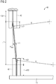
- FIG. 2 shows one of the support plate assemblies 40 in detail.
- the corresponding reference numerals are analogous to FIG. 1 used.
- a portion of the damper mass 20 is attached to the lower bearing 42, which is connected via the support plate 41 with a fixed bearing 42.
- the lower of the two bearings 42 is deflected by a deflection Amax.
- This deflection Amax is intended to represent the maximum deflection that occurs during operation of the damper mass 20.
- the bearings 42 each have a clamping region 420 and a bending gate 421.
- the clamping area 420 is to be understood as the area in which the support plate 41 is attached. This can be done not only by clamping but also by other known fastening measures or combinations thereof.
- the bending gate 421 is the area of the bearing 42, in which the support plate 41 can bend and thus only the movement of the damper mass 20 is made possible. Also shown is the free length L, which represents the actual oscillating length and thus has an influence on the natural frequency of the arrangement.
- the drawn radii R should represent the curvature of the bending gate 421. With this curvature can be controlled by the construction of the bearing 42, that the support plate 41 does not deform outside specifiable requirements. These specifiable requirements may be, for example, maximum bending stresses, which are due to the bending radius can arise. Here, it is particularly desirable that the stresses that occur in the support plate 41 remain below the fatigue strength of the support plate 41.
- FIG. 3 shows one of the bearings 42 in a more detailed representation. It is while maintaining the reference numerals FIG. 2 the clamping area 420 and the bending gate 421 can be seen.
- a support plate 41 is not shown for clarity.
- the bending gate 421 is divided into a Schmiege Scheme 421S and a separation region 421A.
- the lubrication region 421S is separated from the detachment region 421A by the detachment point 421P.
- the detachment point 421P is the point up to which the support plate 41 snuggles against the bending slot 421 and from which the carrier plate 41 separates from the bending slot 421, in each case viewed from the clamping area 420.
- the separation point 421P migrates with the deflection of the support plate 41 along the bending gate 421.
- the Schmiege Scheme 421S has a radius RS and the separation region 421A has a radius RA.
- the regions 421P, 421S and the radii RA and RS are not true to scale and dependent on the respective design. It is conceivable that the minimum separation area 421A occurring at the maximum deflection passes directly into the radius RO in order to obtain an even more compact bearing 42. It is also conceivable that with decreasing frequency of contact A reduction of the radius already takes place with a specific detachment point 421P even within the maximum Schmiege Schemes 421S, since the load of the support plate 41 is not increased despite the smaller bending radius due to the lower frequency of the support plate 41.
- the bearing 42 is constructed symmetrically with respect to.
- the reference numerals for the left and the right side for the sake of clarity, only once shown.
- the radii RS, RA occur on both sides.
- the radii RS, RA are chosen differently depending on the load from side to side.
- a radius RO which is attached to both sides of the bearing opening. This much smaller radius is provided only for the case that the support plate 41 is bent over the edge of the bending slat 421 under extreme deflection. This case is considered to be so rare that the radius RO is to be interpreted only for a small number of bends of the support plate 41 over the radius RO.
- FIG. 4 shows a further embodiment of a bearing 42 with a clamping region 420 and a bending gate 421, which is at an angle ⁇ on a rest position 100 of the support plate 41.
- the bending gate 421 has a radius R, which is designed to reduce the bending stresses in the support plate 41.
- the rest position 100 describes the position that occupy the support plates in the stationary state of the machine tool. In this embodiment, the support plate in the rest position is not straight but partially bent over the bending gate 421.
- the support plate 41 is in FIG4 deflected to the right.
- FIG. 5 shows the bearing 42 FIG. 4 while maintaining the reference numerals.
- the support plate 41 is deflected to the left and it is clear to see that the direction of the bend has not changed, but only the amplitude of the deflection. This advantageously leads to the Bending stress in the support plate 41 performs no sign changes.
- the bearing 42 according to FIG. 4 and FIG is preferably to be interpreted so that the maximum deflection, which can perform the support plate 41, at most leads to a reduction in the bending stress to zero, but does not cause a change of sign.
- FIG. 6 shows a possible embodiment of a machine tool 1, which has an actuator 2, a machine element 10 and a damper mass 20.
- the actuator 2 may be formed, for example, as a highly dynamic and thus vibrations causing cutting tool.
- the machine element 10 is formed in this case as a kind of table, but there are any other embodiments conceivable in which a vibration damping is desirable.
- the damper mass 20 is secured by means of support plate assemblies 40 on the machine element 10.
- the support plate assemblies 40 each have a support plate 41 and two bearings 42.
- a linear motor LM whose passive part PLM is attached to the movable damper mass 20 and whose active part ALM is attached to the machine element 10 for damping the vibrations occurring there.
- the arrangement has the advantage that the complete damper mass, including the actuators, that is to say the linear motor LM, can be integrated into the machine element 10 on or even depending on the design. This is space-saving and efficient.
- FIG. 7 shows while maintaining the reference numerals FIG. 6 a possible embodiment in which the damper mass 20 is not suspended but is mounted on the support plate assemblies 40.
- this arrangement would be an unstable system because any deflection of the damper mass 20 would cause the damper mass 20 to fall to the ground following the weight force.
- the attractive force between the active part ALM and the passive part PLM of the linear motor LM is many orders of magnitude greater than the weight force of the damper mass 20, such an arrangement is possible.
- This has the great advantage that the damper mass 20 additionally decoupled from the machine element 10 and any vibrations that may occur here are not transmitted to the machine element 10.
- FIG. 8 shows while retaining the reference numerals from the FIGS. 6 and 7 a machine tool 1, the damper mass 20 is movably mounted on the machine element 10 by means of the support plate assemblies 40.
- the passive part PLM of the linear motor LM is further attached to the damper mass 20, the active part ALM of the linear motor LM, however, is mounted on the bottom side and can exert forces on the damper mass 20 without exerting forces on the machine element 10. This may also be advantageous in certain applications.
- FIG. 9 shows while maintaining the reference numerals FIGS. 6 to 8 an extension of the known system by a second linear motor LM2.
- a passive part PLM2 of the second linear motor LM2 is likewise fastened to the movable damper mass 20, and an active part ALM2 of the second linear motor LM2 is fastened to an auxiliary frame 45.
- the invention relates to a machine tool 1, comprising a machine element 10, a damper mass 20, support plate assemblies 40 and a linear motor LM.
- a machine tool 1 which enables effective and low-maintenance vibration damping
- the support plate assemblies 40 each have a support plate 41 and bearing 42, wherein the support plate 41 is clamped or fixed in the bearings 42.
- the damper mass 20 is for damping vibrations S of the machine tool 1 by means of the linear motor LM in operative connection with the machine element 10 and / or the machine tool. 1
Landscapes
- Engineering & Computer Science (AREA)
- General Engineering & Computer Science (AREA)
- Mechanical Engineering (AREA)
- Physics & Mathematics (AREA)
- Electromagnetism (AREA)
- Acoustics & Sound (AREA)
- Aviation & Aerospace Engineering (AREA)
- Auxiliary Devices For Machine Tools (AREA)
- Machine Tool Units (AREA)
- Vibration Prevention Devices (AREA)
Priority Applications (5)
| Application Number | Priority Date | Filing Date | Title |
|---|---|---|---|
| EP16155902.6A EP3208036A1 (fr) | 2016-02-16 | 2016-02-16 | Amortissement d'oscillations d'une machine-outil |
| PCT/EP2017/053472 WO2017140760A1 (fr) | 2016-02-16 | 2017-02-16 | Amortissement de vibrations dans une machine |
| EP17705410.3A EP3397423B1 (fr) | 2016-02-16 | 2017-02-16 | Amortissement d'oscillations d'une machine-outil |
| CN201780008212.6A CN108602167B (zh) | 2016-02-16 | 2017-02-16 | 机器振动的抑制 |
| US16/077,792 US10744608B2 (en) | 2016-02-16 | 2017-02-16 | Damping of vibrations of a machine |
Applications Claiming Priority (1)
| Application Number | Priority Date | Filing Date | Title |
|---|---|---|---|
| EP16155902.6A EP3208036A1 (fr) | 2016-02-16 | 2016-02-16 | Amortissement d'oscillations d'une machine-outil |
Publications (1)
| Publication Number | Publication Date |
|---|---|
| EP3208036A1 true EP3208036A1 (fr) | 2017-08-23 |
Family
ID=55405151
Family Applications (2)
| Application Number | Title | Priority Date | Filing Date |
|---|---|---|---|
| EP16155902.6A Withdrawn EP3208036A1 (fr) | 2016-02-16 | 2016-02-16 | Amortissement d'oscillations d'une machine-outil |
| EP17705410.3A Active EP3397423B1 (fr) | 2016-02-16 | 2017-02-16 | Amortissement d'oscillations d'une machine-outil |
Family Applications After (1)
| Application Number | Title | Priority Date | Filing Date |
|---|---|---|---|
| EP17705410.3A Active EP3397423B1 (fr) | 2016-02-16 | 2017-02-16 | Amortissement d'oscillations d'une machine-outil |
Country Status (4)
| Country | Link |
|---|---|
| US (1) | US10744608B2 (fr) |
| EP (2) | EP3208036A1 (fr) |
| CN (1) | CN108602167B (fr) |
| WO (1) | WO2017140760A1 (fr) |
Families Citing this family (4)
| Publication number | Priority date | Publication date | Assignee | Title |
|---|---|---|---|---|
| DE102018007222A1 (de) * | 2018-09-13 | 2020-03-19 | Peter Lorenz | Läuteantrieb für eine Glocke und Verfahren zum Läuten einer Glocke |
| EP3640496A1 (fr) * | 2018-10-18 | 2020-04-22 | Siemens Aktiengesellschaft | Amortisseur de vibrations actif pouvant être inséré dans des orientations multiples |
| KR102386263B1 (ko) * | 2019-12-23 | 2022-04-13 | 김남영 | 로프 기초를 이용한 면진 구조 |
| JP7359128B2 (ja) * | 2020-10-28 | 2023-10-11 | トヨタ自動車株式会社 | ダイナミックダンパ |
Citations (10)
| Publication number | Priority date | Publication date | Assignee | Title |
|---|---|---|---|---|
| GB373827A (en) * | 1930-07-08 | 1932-06-02 | Bianchi Giuseppe | Device for reducing the limit of deflection in leaf springs |
| DE579637C (de) * | 1933-06-29 | Heinrich Schieferstein | Elastisches Mittel mit der zur Erzeugung von Schwingungen nach Patent 541307 erforderlichen Charakteristik | |
| US4710656A (en) * | 1986-12-03 | 1987-12-01 | Studer Philip A | Spring neutralized magnetic vibration isolator |
| JPH0658368A (ja) * | 1992-08-10 | 1994-03-01 | Hitachi Seiko Ltd | 振動制御装置の吸振器 |
| GB2320547A (en) * | 1996-12-18 | 1998-06-24 | Sikorsky Aircraft Corp | Vibration absorber |
| JP2002061703A (ja) * | 2000-08-21 | 2002-02-28 | Nikon Corp | 防振方法及びこの防振方法を用いた防振装置 |
| US20060061021A1 (en) * | 2004-09-21 | 2006-03-23 | Dittmar Edbert E L | Bifurcated spring system with strain control cams |
| US20070243033A1 (en) * | 2006-04-04 | 2007-10-18 | Kazutada Hashimoto | Chattering vibration inhibiting mechanism of machine tool |
| EP2174748A1 (fr) | 2008-10-10 | 2010-04-14 | Siemens Aktiengesellschaft | Machine-outil et procédé d'amortissement d'oscillations d'un élément de machine d'une machine-outil |
| JP2011033089A (ja) * | 2009-07-30 | 2011-02-17 | Kurashiki Kako Co Ltd | マスダンパ |
Family Cites Families (10)
| Publication number | Priority date | Publication date | Assignee | Title |
|---|---|---|---|---|
| FR2379732A1 (fr) * | 1977-02-04 | 1978-09-01 | Europ Propulsion | Dispositif de stabilisation horizontale d'une masse a support inertiel vertical |
| DE3917408A1 (de) * | 1988-06-06 | 1989-12-07 | Takenaka Corp | Daempfungssockel |
| CN1016983B (zh) | 1988-11-24 | 1992-06-10 | 清华大学 | 电磁式弹簧刚度连续可调消振器 |
| JPH07113395B2 (ja) * | 1991-04-01 | 1995-12-06 | 科学技術庁航空宇宙技術研究所長 | 多次元ダンパ装置 |
| DE102005056603B4 (de) * | 2005-11-28 | 2019-02-21 | Siemens Aktiengesellschaft | Verfahren zur Reduktion von während eines Bearbeitungsvorgangs auftretenden Schwingungen eines Maschinenelementes und/oder eines Werkstücks |
| EP2075484A1 (fr) * | 2007-12-31 | 2009-07-01 | Nederlandse Organisatie voor toegepast-natuurwetenschappelijk Onderzoek TNO | Système d'isolation à vibration active ayant une masse de référence d'inertie |
| JP5160980B2 (ja) | 2008-07-08 | 2013-03-13 | オークマ株式会社 | 振動抑制方法及び装置 |
| CN102777535B (zh) * | 2012-08-15 | 2014-11-05 | 潍柴动力股份有限公司 | 一种质量减振器及其检测方法 |
| US9689453B2 (en) | 2014-02-06 | 2017-06-27 | Asm Technology Singapore Pte. Ltd. | Active vibration absorber |
| CN104264854B (zh) * | 2014-08-28 | 2015-10-28 | 华北水利水电大学 | 一种磁悬浮式水平调谐质量阻尼器 |
-
2016
- 2016-02-16 EP EP16155902.6A patent/EP3208036A1/fr not_active Withdrawn
-
2017
- 2017-02-16 WO PCT/EP2017/053472 patent/WO2017140760A1/fr not_active Ceased
- 2017-02-16 EP EP17705410.3A patent/EP3397423B1/fr active Active
- 2017-02-16 CN CN201780008212.6A patent/CN108602167B/zh active Active
- 2017-02-16 US US16/077,792 patent/US10744608B2/en active Active
Patent Citations (10)
| Publication number | Priority date | Publication date | Assignee | Title |
|---|---|---|---|---|
| DE579637C (de) * | 1933-06-29 | Heinrich Schieferstein | Elastisches Mittel mit der zur Erzeugung von Schwingungen nach Patent 541307 erforderlichen Charakteristik | |
| GB373827A (en) * | 1930-07-08 | 1932-06-02 | Bianchi Giuseppe | Device for reducing the limit of deflection in leaf springs |
| US4710656A (en) * | 1986-12-03 | 1987-12-01 | Studer Philip A | Spring neutralized magnetic vibration isolator |
| JPH0658368A (ja) * | 1992-08-10 | 1994-03-01 | Hitachi Seiko Ltd | 振動制御装置の吸振器 |
| GB2320547A (en) * | 1996-12-18 | 1998-06-24 | Sikorsky Aircraft Corp | Vibration absorber |
| JP2002061703A (ja) * | 2000-08-21 | 2002-02-28 | Nikon Corp | 防振方法及びこの防振方法を用いた防振装置 |
| US20060061021A1 (en) * | 2004-09-21 | 2006-03-23 | Dittmar Edbert E L | Bifurcated spring system with strain control cams |
| US20070243033A1 (en) * | 2006-04-04 | 2007-10-18 | Kazutada Hashimoto | Chattering vibration inhibiting mechanism of machine tool |
| EP2174748A1 (fr) | 2008-10-10 | 2010-04-14 | Siemens Aktiengesellschaft | Machine-outil et procédé d'amortissement d'oscillations d'un élément de machine d'une machine-outil |
| JP2011033089A (ja) * | 2009-07-30 | 2011-02-17 | Kurashiki Kako Co Ltd | マスダンパ |
Also Published As
| Publication number | Publication date |
|---|---|
| WO2017140760A1 (fr) | 2017-08-24 |
| CN108602167A (zh) | 2018-09-28 |
| US10744608B2 (en) | 2020-08-18 |
| US20190047103A1 (en) | 2019-02-14 |
| EP3397423B1 (fr) | 2021-11-24 |
| EP3397423A1 (fr) | 2018-11-07 |
| CN108602167B (zh) | 2020-09-18 |
Similar Documents
| Publication | Publication Date | Title |
|---|---|---|
| DE69617859T2 (de) | Dynamischer Schwingungsdämpfer | |
| DE112020000562B4 (de) | Elektromagnetischer Dämpfer mit Luftfeder | |
| DE112019000948B4 (de) | Dämpfer mit elektromagnetischem Aktuator | |
| EP0127741B1 (fr) | Système de suspension pour un véhicule automobile | |
| EP3052833B1 (fr) | Siège de véhicule ou cabine de véhicule doté(e) d'un dispositif de suspension et véhicule utilitaire | |
| DE69625870T2 (de) | Lagereinheit | |
| DE102014210489B4 (de) | Fliehkraftpendel | |
| DE102010026569B4 (de) | Regelungseinrichtung zur Reduzierung einer Schwingungsbewegung einer federkraftbeaufschlagten schwingenden Vorrichtung | |
| DE60205370T2 (de) | Schwingungstilger | |
| DE69405266T2 (de) | Dynamischer Schwingungsdämpfer | |
| DE3410473A1 (de) | Federungssystem fuer ein kraftfahrzeug | |
| DE102014200162B4 (de) | Maschine, insbesondere Verbrennungskraftmaschine, mit einem bewegbaren Bauteil, das mit einem schaltbaren Ventil ausgerüstet ist | |
| EP0134749B1 (fr) | Installation de palier élastique à amortissement, en particulier pour machines électriques | |
| EP2408632B1 (fr) | Système de suspension électromécanique actif pour un châssis de véhicule automobile | |
| EP3208036A1 (fr) | Amortissement d'oscillations d'une machine-outil | |
| EP2921343A2 (fr) | Dispositif destiné à équiper d'une suspension une partie supérieure de ressort dans au moins une direction dans l'espace par rapport à une partie inférieure de ressort mobile par rapport à celle-ci | |
| DE3204750C2 (de) | Magnetisch gelagerte Turbomolekularpumpe | |
| DE3116600A1 (de) | "motorbefestigungsanordnung" | |
| DE69925670T2 (de) | Verfahren und Vorrichtung zur Kontrolle und Unterdrückung von Schwingungen in einem linearen Reluktanzmotor | |
| DE102013218055A1 (de) | Lagervorrichtung einer Querblattfeder, die im Bereich einer Fahrzeugachse eines Fahrzeuges montierbar ist | |
| DE102008038728A1 (de) | Fertigungsmaschine für unrunde Werkstücke | |
| DE102014109191A1 (de) | Federungssystem für Fahrzeuge und Verfahren zum Federn von Fahrzeugteilen | |
| DE69304171T2 (de) | Elektromotor und Apparat, der diesen Elektromotor enthält | |
| EP0867627A2 (fr) | Système d'amortissement pour rotors suspendus magnétiquement | |
| DE102021131407B4 (de) | Elektromotor, insbesondere Reluktanzmotor |
Legal Events
| Date | Code | Title | Description |
|---|---|---|---|
| PUAI | Public reference made under article 153(3) epc to a published international application that has entered the european phase |
Free format text: ORIGINAL CODE: 0009012 |
|
| STAA | Information on the status of an ep patent application or granted ep patent |
Free format text: STATUS: THE APPLICATION HAS BEEN PUBLISHED |
|
| AK | Designated contracting states |
Kind code of ref document: A1 Designated state(s): AL AT BE BG CH CY CZ DE DK EE ES FI FR GB GR HR HU IE IS IT LI LT LU LV MC MK MT NL NO PL PT RO RS SE SI SK SM TR |
|
| AX | Request for extension of the european patent |
Extension state: BA ME |
|
| RAP1 | Party data changed (applicant data changed or rights of an application transferred) |
Owner name: SIEMENS AKTIENGESELLSCHAFT |
|
| STAA | Information on the status of an ep patent application or granted ep patent |
Free format text: STATUS: REQUEST FOR EXAMINATION WAS MADE |
|
| 17P | Request for examination filed |
Effective date: 20180514 |
|
| RBV | Designated contracting states (corrected) |
Designated state(s): AL AT BE BG CH CY CZ DE DK EE ES FI FR GB GR HR HU IE IS IT LI LT LU LV MC MK MT NL NO PL PT RO RS SE SI SK SM TR |
|
| STAA | Information on the status of an ep patent application or granted ep patent |
Free format text: STATUS: EXAMINATION IS IN PROGRESS |
|
| 17Q | First examination report despatched |
Effective date: 20200619 |
|
| STAA | Information on the status of an ep patent application or granted ep patent |
Free format text: STATUS: THE APPLICATION IS DEEMED TO BE WITHDRAWN |
|
| 18D | Application deemed to be withdrawn |
Effective date: 20211130 |