EP3208041A1 - Lokalisierungsbolzenbaugruppe - Google Patents
Lokalisierungsbolzenbaugruppe Download PDFInfo
- Publication number
- EP3208041A1 EP3208041A1 EP17154901.7A EP17154901A EP3208041A1 EP 3208041 A1 EP3208041 A1 EP 3208041A1 EP 17154901 A EP17154901 A EP 17154901A EP 3208041 A1 EP3208041 A1 EP 3208041A1
- Authority
- EP
- European Patent Office
- Prior art keywords
- locating pin
- drive rod
- pin
- base
- finger
- Prior art date
- Legal status (The legal status is an assumption and is not a legal conclusion. Google has not performed a legal analysis and makes no representation as to the accuracy of the status listed.)
- Granted
Links
Images
Classifications
-
- B—PERFORMING OPERATIONS; TRANSPORTING
- B23—MACHINE TOOLS; METAL-WORKING NOT OTHERWISE PROVIDED FOR
- B23Q—DETAILS, COMPONENTS, OR ACCESSORIES FOR MACHINE TOOLS, e.g. ARRANGEMENTS FOR COPYING OR CONTROLLING; MACHINE TOOLS IN GENERAL CHARACTERISED BY THE CONSTRUCTION OF PARTICULAR DETAILS OR COMPONENTS; COMBINATIONS OR ASSOCIATIONS OF METAL-WORKING MACHINES, NOT DIRECTED TO A PARTICULAR RESULT
- B23Q3/00—Devices holding, supporting, or positioning work or tools, of a kind normally removable from the machine
- B23Q3/18—Devices holding, supporting, or positioning work or tools, of a kind normally removable from the machine for positioning only
-
- B—PERFORMING OPERATIONS; TRANSPORTING
- B25—HAND TOOLS; PORTABLE POWER-DRIVEN TOOLS; MANIPULATORS
- B25B—TOOLS OR BENCH DEVICES NOT OTHERWISE PROVIDED FOR, FOR FASTENING, CONNECTING, DISENGAGING, OR HOLDING
- B25B5/00—Clamps
- B25B5/06—Arrangements for positively actuating jaws
- B25B5/061—Arrangements for positively actuating jaws with fluid drive
-
- B—PERFORMING OPERATIONS; TRANSPORTING
- B25—HAND TOOLS; PORTABLE POWER-DRIVEN TOOLS; MANIPULATORS
- B25B—TOOLS OR BENCH DEVICES NOT OTHERWISE PROVIDED FOR, FOR FASTENING, CONNECTING, DISENGAGING, OR HOLDING
- B25B5/00—Clamps
- B25B5/06—Arrangements for positively actuating jaws
- B25B5/061—Arrangements for positively actuating jaws with fluid drive
- B25B5/062—Arrangements for positively actuating jaws with fluid drive with clamping means pivoting around an axis parallel to the pressing direction
-
- B—PERFORMING OPERATIONS; TRANSPORTING
- B25—HAND TOOLS; PORTABLE POWER-DRIVEN TOOLS; MANIPULATORS
- B25B—TOOLS OR BENCH DEVICES NOT OTHERWISE PROVIDED FOR, FOR FASTENING, CONNECTING, DISENGAGING, OR HOLDING
- B25B5/00—Clamps
- B25B5/06—Arrangements for positively actuating jaws
- B25B5/08—Arrangements for positively actuating jaws using cams
- B25B5/087—Arrangements for positively actuating jaws using cams actuated by a hydraulic or pneumatic piston
Definitions
- the present invention relates to pin clamp assemblies, and, more particularly, to a pin clamp assembly having a locating pin, a drive rod, and a finger such that the locating pin and the finger can be rotated or replaced without removal and disassembly of the entire pin clamp assembly.
- a pin clamp assembly typically includes a locating pin extending from a body that is inserted into a hole on a workpiece, such as a sheet metal automotive body panel.
- Pin clamp assemblies generally employ either a stationary or rectilinearly moving locating pin, and they often employ a combination of linearly and rotationally moving components to hold the workpiece.
- pin clamp assemblies are powered by actuators employing pneumatic or hydraulic fluid pressure.
- a finger extends from within the locating pin as the locating pin retracts in order to hold the workpiece against the body of the clamp.
- Pin clamps with moveable locating pins often employ the movement of the locating pin to extend the finger. In other words, movement of the locating pin generally moves the finger as well.
- the finger is at a fixed direction with respect to the pin clamp assembly. If a different finger direction is desired, the entire pin clamp assembly needs to be removed and either turned or replaced with a different pin clamp assembly to achieve the desired finger direction. The process to adjust or remove a pin clamp assembly is generally cumbersome and costly as it ceases production for a longer duration of time and increases labor cost.
- the present invention provides an improved locating pin assembly that comprises a locating pin, a drive rod, and a finger such that the finger is easily rotatable to a first and a second position relative to the base of the locating pin assembly.
- the present invention in one form is directed to a locating pin assembly that includes a locating pin movable between extended and retracted positions.
- the locating pin includes a locating pin top having a top end and a bottom end, a locating pin base receiving the bottom end of the locating pin top, and a dowel pin configured to couple the locating pin top and locating pin base together.
- the locating pin assembly also includes a drive rod moveable relative to the locating pin.
- the drive rod includes a drive rod top having a top end and a bottom end and a drive rod base partially housing the drive rod top such that the bottom end of the drive rod top is housed within the drive rod base.
- the locating pin assembly further includes a finger coupled to the drive rod and movable between extended and fully retracted positions, the finger is extended by the drive rod without movement of the locating pin, and the finger is rotatable from a first position to a second position.
- the present invention in another form is directed to a pin clamp assembly that includes a body, an actuator coupled to the body, and a locating pin assembly coupled to the body and movable between extended and retracted positions.
- the locating pin assembly includes a locating pin, a drive rod actuated by the actuator and movable relative to the locating pin, and a finger coupled to the drive rod and movable between extended and fully retracted positions.
- the finger is rotatable from a first position to a second position relative to the body.
- the finger is extended by the drive rod without movement of the locating pin upon actuation by the actuator.
- the pin clamp assembly also includes a cam movable relative to the locating pin and the drive rod, wherein continued retraction of the drive rod after the finger has extended causes the cam to move out from a slot in the body to allow the locating pin to retract.
- the present invention in yet another form is directed to a method of adjusting a pin clamp assembly.
- the method includes the steps of providing the pin clamp assembly that includes a locating pin assembly that includes a locating pin movable between extended and retracted positions.
- the locating pin includes a locating pin top having a top end and a bottom end, a locating pin base receiving the bottom end of the locating pin top, and a dowel pin configured to couple the locating pin top and locating pin base together.
- the locating pin assembly also includes a drive rod moveable relative to the locating pin.
- the drive rod includes a drive rod top having a top end and a bottom end and a drive rod base partially housing the drive rod top such that the bottom end of the drive rod top is housed within the drive rod base.
- the locating pin assembly further includes a finger coupled to the drive rod and movable between extended and fully retracted positions.
- the finger is extended by the drive rod without movement of the locating pin, and the finger is rotatable from a first position to a second position.
- the method includes the further steps of removing the dowel pin of the locating pin, positioning the finger from the first position to the second position by rotating the finger without moving the locating pin base and the drive rod base, and inserting the dowel pin into the locating pin.
- An advantage of the present invention is that modification of the direction in which the finger extends can be easily adjusted without the removal of the entire pin clamp assembly.
- Another advantage of the present invention is that the top portion of the drive rod rotates with the locating pin top, which maintains the relationships of the components of the pin clamp assembly therebetween.
- Yet another advantage of the present invention is that the locating pin top can be changed at the initial assembly or in the field by removing the dowel pin and installing a different locating pin top and finger, thereby allowing a user to easily change locating pin diameters.
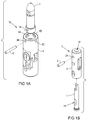
- the locating pin 10 includes a locating pin base 8, a locating pin top 7, and a dowel pin 6.
- the drive rod 15 includes a drive rod top 1, a drive rod base 2, and a dowel pin 3.
- the inventive locating pin assembly 20 may be coupled to a known body and actuator as described in U.S. Patent No. 8,413,970 entitled “PIN CLAMP ASSEMBLY", which is incorporated herein by reference.
- the locating pin top 7 has a proximal end at which at least one hole 7A is located for receiving the dowel pin 6 and a distal end where the finger 5 is positioned. Additionally, instead of just one hole 7A, the locating pin top 7 may have multiple holes positioned around its proximal end (not shown).
- the locating pin base 8 has a top end thereof with holes 8A, 8B, 8C, and 8D, which are associated with the corresponding hole 7A of the locating pin top 7.
- the dowel pin 6 may be inserted into at least one of the holes 8A, 8B, 8C, and 8D in order to secure the locating pin top 7.
- the locating pin top 7 and the locating pin base 8 are rotatable relative to each other such that when the dowel pin 6 is removed the locating pin top 7 may be rotated to various positions as the locating pin base 8 remains stationary.
- the drive rod top 1 has a hole 1A which receives the dowel pin 6 of the locating pin 10.
- the drive rod base 2 has a bottom end and a top end with a hole 12, as well as a hole 2A for receiving the dowel pin 3.
- the drive rod 15 is shown assembled as follows: the top end of the drive rod top 1 is inserted into the bottom end of the drive rod base 2 until the distal-most portion of drive rod top 1 is proximal to hole 12, then the dowel pin 3 is inserted into hole 2A. Prior to final assembly of the locating pin assembly 20, the drive rod top 1 is freely able to rotate within - but unable to slide downward into - the drive rod base 2.
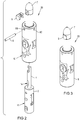
- FIG. 3 there is shown an assembled locating pin assembly 20 with the finger 5 in a first position relative to the locating pin base 8.
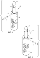
- FIG. 4 there is shown an assembled locating pin assembly 20 with the exception of the dowel pin 6, which is shown to be removed.
- the finger 5 is shown in a first position relative to the locating pin base 8, with the dowel pin 6 to be inserted into hole 8B.
- the locating pin top 7 and accompanying finger 5 can be rotated to a second position relative to the locating pin base 8.
- the dowel pin 6 can then be inserted into hole 8C ( Fig. 5 ).
- the rotational positioning is shown to be in 90 degree increments; however, any increment between 0 and 360 degrees may be used.
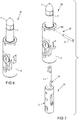
- FIG. 6 there is shown an assembled locating pin assembly 20 with the finger 5 in a second position relative to the locating pin base 8.
- the locating pin top 7 (and accompanying finger 5 and drive rod top 1) is in a second position which is rotated 90 degrees from the first position relative to the locating pin base 8 of the locating pin assembly 20 as shown in Fig. 2 .
- the position of the drive rod base 2 remains the same as it was prior to rotation of the locating pin top 7, thereby retaining the ability to extend/retract locating pin top 7 and extend/retract finger 5.
- the position of the finger 5 may be easily adjusted or removed without removal and disassembly of the entire pin clamp assembly 20, which may additionally be coupled to a main body and actuator.
- the dowel pin 6 is removed from a first hole (e.g., 8B) that corresponds to the first position.
- the finger 5 may be rotated from the first position to the second position.
- the locating pin top 7 may be rotated, which thereby rotates the drive rod top 1 and the accompanying finger 5 which is displaced within the locating pin top 7.
- the finger 5, the locating pin top 7, and the drive rod top 1 are all rotated independently from and without removing or rotating the locating pin base 8 and the drive rod base 2.
- the locating pin top 7 may be removed and replaced with another locating pin top, for example a locating pin top with a different diameter.
- the dowel pin 6 is inserted into a second hole (e.g., 8C) that corresponds to the second position.
Landscapes
- Engineering & Computer Science (AREA)
- Mechanical Engineering (AREA)
- Automatic Assembly (AREA)
- Hand Tools For Fitting Together And Separating, Or Other Hand Tools (AREA)
Applications Claiming Priority (1)
| Application Number | Priority Date | Filing Date | Title |
|---|---|---|---|
| US201662292561P | 2016-02-08 | 2016-02-08 |
Publications (2)
| Publication Number | Publication Date |
|---|---|
| EP3208041A1 true EP3208041A1 (de) | 2017-08-23 |
| EP3208041B1 EP3208041B1 (de) | 2021-03-24 |
Family
ID=58009668
Family Applications (1)
| Application Number | Title | Priority Date | Filing Date |
|---|---|---|---|
| EP17154901.7A Active EP3208041B1 (de) | 2016-02-08 | 2017-02-07 | Lokalisierungsbolzenbaugruppe |
Country Status (3)
| Country | Link |
|---|---|
| US (1) | US10836005B2 (de) |
| EP (1) | EP3208041B1 (de) |
| ES (1) | ES2864953T3 (de) |
Families Citing this family (3)
| Publication number | Priority date | Publication date | Assignee | Title |
|---|---|---|---|---|
| US20230135381A1 (en) * | 2021-11-01 | 2023-05-04 | Legacy Industries | Floating system and method for a tool |
| DE102023127106A1 (de) * | 2023-10-05 | 2025-04-10 | Destaco Europe Gmbh | Zentrierspannvorrichtung |
| CN119589467A (zh) * | 2024-12-11 | 2025-03-11 | 北京星航机电装备有限公司 | 一种回转类零件专用工装及上线加工方法 |
Citations (2)
| Publication number | Priority date | Publication date | Assignee | Title |
|---|---|---|---|---|
| US20050040578A1 (en) * | 2003-08-21 | 2005-02-24 | Sawdon Edwin G. | Sealed pin locating and clamping apparatus |
| US8413970B2 (en) | 2007-06-19 | 2013-04-09 | Phd, Inc. | Pin clamp assembly |
Family Cites Families (21)
| Publication number | Priority date | Publication date | Assignee | Title |
|---|---|---|---|---|
| US2005040A (en) | 1932-03-25 | 1935-06-18 | United Shoe Machinery Corp | Machine for slitting covers attached to heels |
| US5013015A (en) * | 1990-06-11 | 1991-05-07 | General Dynamics Corporation | Mechanically actuated swing clamp |
| DE4335032A1 (de) | 1993-10-14 | 1995-04-20 | Henkenjohann Johann | Sicherung für aus Stäben zusammengesetzten Rolladen |
| MXPA01012811A (es) | 2001-01-18 | 2002-11-04 | Progressive Tool & Ind Co | Posicionador de sujecion. |
| US6435493B1 (en) | 2001-02-06 | 2002-08-20 | Delaware Capital Formation, Inc. | Swing arm clamp mechanism |
| US6786478B2 (en) * | 2002-07-10 | 2004-09-07 | Welker Bearing Company | Locating assembly having an extendable clamping finger |
| US7156385B2 (en) * | 2003-06-03 | 2007-01-02 | Norgren Automotive, Inc. | Linearly adjustable apparatus for locating a workpiece |
| US20050035516A1 (en) | 2003-08-14 | 2005-02-17 | Sawdon Edwin G. | Sealed pin locator clamp |
| US7182326B2 (en) | 2004-04-02 | 2007-02-27 | Phd, Inc. | Pin clamp |
| US7029000B2 (en) * | 2004-09-07 | 2006-04-18 | Btm Corporation | Sealed locking pin locator clamp |
| US7686286B2 (en) * | 2005-08-26 | 2010-03-30 | Delaware Capital Formation, Inc. | Variable thickness pin clamp |
| US7370856B2 (en) | 2005-10-04 | 2008-05-13 | Btm Corporation | Rotating head pin clamp |
| JP4699409B2 (ja) * | 2007-03-20 | 2011-06-08 | 株式会社コガネイ | 位置決めクランプ装置 |
| JP5346542B2 (ja) | 2008-04-24 | 2013-11-20 | パスカルエンジニアリング株式会社 | クランプ装置 |
| WO2009155261A1 (en) | 2008-06-18 | 2009-12-23 | Phd, Inc. | Strip off pin clamp |
| US8459626B2 (en) | 2010-05-28 | 2013-06-11 | Btm Corporation | Pin clamp |
| US9168621B2 (en) | 2011-10-18 | 2015-10-27 | Phd, Inc. | Pin clamp with multi-thickness clamping feature |
| US9314905B2 (en) | 2013-10-08 | 2016-04-19 | Zaytran, Inc. | Locking pin clamp |
| US8950741B1 (en) | 2014-03-03 | 2015-02-10 | Praxis Industries, Llc | Clamping assembly |
| US9486898B2 (en) | 2014-05-21 | 2016-11-08 | Zaytran, Inc. | Sliding head locking pin clamp |
| US9770810B2 (en) | 2014-11-12 | 2017-09-26 | De-Sta-Co Europe Gmbh | Pin clamp |
-
2017
- 2017-02-07 ES ES17154901T patent/ES2864953T3/es active Active
- 2017-02-07 US US15/426,667 patent/US10836005B2/en active Active
- 2017-02-07 EP EP17154901.7A patent/EP3208041B1/de active Active
Patent Citations (2)
| Publication number | Priority date | Publication date | Assignee | Title |
|---|---|---|---|---|
| US20050040578A1 (en) * | 2003-08-21 | 2005-02-24 | Sawdon Edwin G. | Sealed pin locating and clamping apparatus |
| US8413970B2 (en) | 2007-06-19 | 2013-04-09 | Phd, Inc. | Pin clamp assembly |
Also Published As
| Publication number | Publication date |
|---|---|
| US10836005B2 (en) | 2020-11-17 |
| EP3208041B1 (de) | 2021-03-24 |
| ES2864953T3 (es) | 2021-10-14 |
| US20170225282A1 (en) | 2017-08-10 |
Similar Documents
| Publication | Publication Date | Title |
|---|---|---|
| EP3208041A1 (de) | Lokalisierungsbolzenbaugruppe | |
| EP2943634B1 (de) | Montagesystem für eine bauliche abdeckung | |
| JP5971595B2 (ja) | パンチ装置 | |
| EP3597357A1 (de) | Vorrichtung zum setzen von blindnietmuttern | |
| RS58152B1 (sr) | Poboljšani uređaj za proširivanje krajeva cevi | |
| DE202017007488U1 (de) | Verbindungsvorrichtung | |
| US7024909B2 (en) | Non-impact swaging apparatus | |
| DE102014112337A1 (de) | Greifvorrichtung | |
| WO2020234116A1 (de) | Radhalter | |
| EP2879824B1 (de) | Auswucht- oder messadapter | |
| EP4488547A3 (de) | Axialpumpenanordnungen | |
| US20150239084A1 (en) | Multi-tool adaptor | |
| JP2016061335A (ja) | バタフライ弁の組み立て方法及び装置 | |
| EP3117916B1 (de) | Vorrichtung zum bearbeiten eines rohres | |
| DE102011008557B4 (de) | Chirurgisches Halteinstrument für Knochenplatten | |
| US7213803B2 (en) | Clamp and method for operating same | |
| EP2590778A2 (de) | Aktive universelle haltevorrichtung zur halterung eines werkstücks in einer universalspannvorrichtung | |
| US6932333B2 (en) | Swing clamp | |
| US20190001468A1 (en) | Device for Clamping a Part to a Tool | |
| JP6156105B2 (ja) | 電動ドライバ装置 | |
| DE202014102474U1 (de) | Verstellbares Klappenlager | |
| EP3126731B1 (de) | Vorrichtung und verfahren zum befestigen eines optischen gerätes | |
| CN110043123B (zh) | 过渡轴快装结构及所应用的锁具 | |
| KR101580834B1 (ko) | 플랜지 타각 장치 | |
| EP3414412B1 (de) | Modulares zylinderschloss |
Legal Events
| Date | Code | Title | Description |
|---|---|---|---|
| PUAI | Public reference made under article 153(3) epc to a published international application that has entered the european phase |
Free format text: ORIGINAL CODE: 0009012 |
|
| STAA | Information on the status of an ep patent application or granted ep patent |
Free format text: STATUS: THE APPLICATION HAS BEEN PUBLISHED |
|
| AK | Designated contracting states |
Kind code of ref document: A1 Designated state(s): AL AT BE BG CH CY CZ DE DK EE ES FI FR GB GR HR HU IE IS IT LI LT LU LV MC MK MT NL NO PL PT RO RS SE SI SK SM TR |
|
| AX | Request for extension of the european patent |
Extension state: BA ME |
|
| STAA | Information on the status of an ep patent application or granted ep patent |
Free format text: STATUS: REQUEST FOR EXAMINATION WAS MADE |
|
| 17P | Request for examination filed |
Effective date: 20171116 |
|
| RBV | Designated contracting states (corrected) |
Designated state(s): AL AT BE BG CH CY CZ DE DK EE ES FI FR GB GR HR HU IE IS IT LI LT LU LV MC MK MT NL NO PL PT RO RS SE SI SK SM TR |
|
| GRAP | Despatch of communication of intention to grant a patent |
Free format text: ORIGINAL CODE: EPIDOSNIGR1 |
|
| STAA | Information on the status of an ep patent application or granted ep patent |
Free format text: STATUS: GRANT OF PATENT IS INTENDED |
|
| INTG | Intention to grant announced |
Effective date: 20201218 |
|
| GRAS | Grant fee paid |
Free format text: ORIGINAL CODE: EPIDOSNIGR3 |
|
| GRAA | (expected) grant |
Free format text: ORIGINAL CODE: 0009210 |
|
| STAA | Information on the status of an ep patent application or granted ep patent |
Free format text: STATUS: THE PATENT HAS BEEN GRANTED |
|
| AK | Designated contracting states |
Kind code of ref document: B1 Designated state(s): AL AT BE BG CH CY CZ DE DK EE ES FI FR GB GR HR HU IE IS IT LI LT LU LV MC MK MT NL NO PL PT RO RS SE SI SK SM TR |
|
| REG | Reference to a national code |
Ref country code: GB Ref legal event code: FG4D |
|
| REG | Reference to a national code |
Ref country code: CH Ref legal event code: EP |
|
| REG | Reference to a national code |
Ref country code: IE Ref legal event code: FG4D |
|
| REG | Reference to a national code |
Ref country code: AT Ref legal event code: REF Ref document number: 1374008 Country of ref document: AT Kind code of ref document: T Effective date: 20210415 Ref country code: DE Ref legal event code: R096 Ref document number: 602017035055 Country of ref document: DE |
|
| REG | Reference to a national code |
Ref country code: LT Ref legal event code: MG9D |
|
| PG25 | Lapsed in a contracting state [announced via postgrant information from national office to epo] |
Ref country code: HR Free format text: LAPSE BECAUSE OF FAILURE TO SUBMIT A TRANSLATION OF THE DESCRIPTION OR TO PAY THE FEE WITHIN THE PRESCRIBED TIME-LIMIT Effective date: 20210324 Ref country code: GR Free format text: LAPSE BECAUSE OF FAILURE TO SUBMIT A TRANSLATION OF THE DESCRIPTION OR TO PAY THE FEE WITHIN THE PRESCRIBED TIME-LIMIT Effective date: 20210625 Ref country code: FI Free format text: LAPSE BECAUSE OF FAILURE TO SUBMIT A TRANSLATION OF THE DESCRIPTION OR TO PAY THE FEE WITHIN THE PRESCRIBED TIME-LIMIT Effective date: 20210324 Ref country code: NO Free format text: LAPSE BECAUSE OF FAILURE TO SUBMIT A TRANSLATION OF THE DESCRIPTION OR TO PAY THE FEE WITHIN THE PRESCRIBED TIME-LIMIT Effective date: 20210624 Ref country code: BG Free format text: LAPSE BECAUSE OF FAILURE TO SUBMIT A TRANSLATION OF THE DESCRIPTION OR TO PAY THE FEE WITHIN THE PRESCRIBED TIME-LIMIT Effective date: 20210624 |
|
| PG25 | Lapsed in a contracting state [announced via postgrant information from national office to epo] |
Ref country code: RS Free format text: LAPSE BECAUSE OF FAILURE TO SUBMIT A TRANSLATION OF THE DESCRIPTION OR TO PAY THE FEE WITHIN THE PRESCRIBED TIME-LIMIT Effective date: 20210324 Ref country code: LV Free format text: LAPSE BECAUSE OF FAILURE TO SUBMIT A TRANSLATION OF THE DESCRIPTION OR TO PAY THE FEE WITHIN THE PRESCRIBED TIME-LIMIT Effective date: 20210324 Ref country code: SE Free format text: LAPSE BECAUSE OF FAILURE TO SUBMIT A TRANSLATION OF THE DESCRIPTION OR TO PAY THE FEE WITHIN THE PRESCRIBED TIME-LIMIT Effective date: 20210324 |
|
| REG | Reference to a national code |
Ref country code: NL Ref legal event code: MP Effective date: 20210324 |
|
| REG | Reference to a national code |
Ref country code: AT Ref legal event code: MK05 Ref document number: 1374008 Country of ref document: AT Kind code of ref document: T Effective date: 20210324 |
|
| PG25 | Lapsed in a contracting state [announced via postgrant information from national office to epo] |
Ref country code: NL Free format text: LAPSE BECAUSE OF FAILURE TO SUBMIT A TRANSLATION OF THE DESCRIPTION OR TO PAY THE FEE WITHIN THE PRESCRIBED TIME-LIMIT Effective date: 20210324 |
|
| REG | Reference to a national code |
Ref country code: ES Ref legal event code: FG2A Ref document number: 2864953 Country of ref document: ES Kind code of ref document: T3 Effective date: 20211014 |
|
| PG25 | Lapsed in a contracting state [announced via postgrant information from national office to epo] |
Ref country code: CZ Free format text: LAPSE BECAUSE OF FAILURE TO SUBMIT A TRANSLATION OF THE DESCRIPTION OR TO PAY THE FEE WITHIN THE PRESCRIBED TIME-LIMIT Effective date: 20210324 Ref country code: EE Free format text: LAPSE BECAUSE OF FAILURE TO SUBMIT A TRANSLATION OF THE DESCRIPTION OR TO PAY THE FEE WITHIN THE PRESCRIBED TIME-LIMIT Effective date: 20210324 Ref country code: LT Free format text: LAPSE BECAUSE OF FAILURE TO SUBMIT A TRANSLATION OF THE DESCRIPTION OR TO PAY THE FEE WITHIN THE PRESCRIBED TIME-LIMIT Effective date: 20210324 Ref country code: SM Free format text: LAPSE BECAUSE OF FAILURE TO SUBMIT A TRANSLATION OF THE DESCRIPTION OR TO PAY THE FEE WITHIN THE PRESCRIBED TIME-LIMIT Effective date: 20210324 Ref country code: AT Free format text: LAPSE BECAUSE OF FAILURE TO SUBMIT A TRANSLATION OF THE DESCRIPTION OR TO PAY THE FEE WITHIN THE PRESCRIBED TIME-LIMIT Effective date: 20210324 |
|
| PG25 | Lapsed in a contracting state [announced via postgrant information from national office to epo] |
Ref country code: IS Free format text: LAPSE BECAUSE OF FAILURE TO SUBMIT A TRANSLATION OF THE DESCRIPTION OR TO PAY THE FEE WITHIN THE PRESCRIBED TIME-LIMIT Effective date: 20210724 Ref country code: RO Free format text: LAPSE BECAUSE OF FAILURE TO SUBMIT A TRANSLATION OF THE DESCRIPTION OR TO PAY THE FEE WITHIN THE PRESCRIBED TIME-LIMIT Effective date: 20210324 Ref country code: SK Free format text: LAPSE BECAUSE OF FAILURE TO SUBMIT A TRANSLATION OF THE DESCRIPTION OR TO PAY THE FEE WITHIN THE PRESCRIBED TIME-LIMIT Effective date: 20210324 Ref country code: PL Free format text: LAPSE BECAUSE OF FAILURE TO SUBMIT A TRANSLATION OF THE DESCRIPTION OR TO PAY THE FEE WITHIN THE PRESCRIBED TIME-LIMIT Effective date: 20210324 Ref country code: PT Free format text: LAPSE BECAUSE OF FAILURE TO SUBMIT A TRANSLATION OF THE DESCRIPTION OR TO PAY THE FEE WITHIN THE PRESCRIBED TIME-LIMIT Effective date: 20210726 |
|
| REG | Reference to a national code |
Ref country code: DE Ref legal event code: R097 Ref document number: 602017035055 Country of ref document: DE |
|
| PG25 | Lapsed in a contracting state [announced via postgrant information from national office to epo] |
Ref country code: DK Free format text: LAPSE BECAUSE OF FAILURE TO SUBMIT A TRANSLATION OF THE DESCRIPTION OR TO PAY THE FEE WITHIN THE PRESCRIBED TIME-LIMIT Effective date: 20210324 Ref country code: AL Free format text: LAPSE BECAUSE OF FAILURE TO SUBMIT A TRANSLATION OF THE DESCRIPTION OR TO PAY THE FEE WITHIN THE PRESCRIBED TIME-LIMIT Effective date: 20210324 |
|
| PLBE | No opposition filed within time limit |
Free format text: ORIGINAL CODE: 0009261 |
|
| STAA | Information on the status of an ep patent application or granted ep patent |
Free format text: STATUS: NO OPPOSITION FILED WITHIN TIME LIMIT |
|
| PG25 | Lapsed in a contracting state [announced via postgrant information from national office to epo] |
Ref country code: SI Free format text: LAPSE BECAUSE OF FAILURE TO SUBMIT A TRANSLATION OF THE DESCRIPTION OR TO PAY THE FEE WITHIN THE PRESCRIBED TIME-LIMIT Effective date: 20210324 |
|
| 26N | No opposition filed |
Effective date: 20220104 |
|
| PG25 | Lapsed in a contracting state [announced via postgrant information from national office to epo] |
Ref country code: IS Free format text: LAPSE BECAUSE OF FAILURE TO SUBMIT A TRANSLATION OF THE DESCRIPTION OR TO PAY THE FEE WITHIN THE PRESCRIBED TIME-LIMIT Effective date: 20210724 |
|
| PG25 | Lapsed in a contracting state [announced via postgrant information from national office to epo] |
Ref country code: MC Free format text: LAPSE BECAUSE OF FAILURE TO SUBMIT A TRANSLATION OF THE DESCRIPTION OR TO PAY THE FEE WITHIN THE PRESCRIBED TIME-LIMIT Effective date: 20210324 |
|
| REG | Reference to a national code |
Ref country code: CH Ref legal event code: PL |
|
| REG | Reference to a national code |
Ref country code: BE Ref legal event code: MM Effective date: 20220228 |
|
| PG25 | Lapsed in a contracting state [announced via postgrant information from national office to epo] |
Ref country code: LU Free format text: LAPSE BECAUSE OF NON-PAYMENT OF DUE FEES Effective date: 20220207 |
|
| PG25 | Lapsed in a contracting state [announced via postgrant information from national office to epo] |
Ref country code: LI Free format text: LAPSE BECAUSE OF NON-PAYMENT OF DUE FEES Effective date: 20220228 Ref country code: IE Free format text: LAPSE BECAUSE OF NON-PAYMENT OF DUE FEES Effective date: 20220207 Ref country code: CH Free format text: LAPSE BECAUSE OF NON-PAYMENT OF DUE FEES Effective date: 20220228 |
|
| PG25 | Lapsed in a contracting state [announced via postgrant information from national office to epo] |
Ref country code: BE Free format text: LAPSE BECAUSE OF NON-PAYMENT OF DUE FEES Effective date: 20220228 |
|
| P01 | Opt-out of the competence of the unified patent court (upc) registered |
Effective date: 20230524 |
|
| PG25 | Lapsed in a contracting state [announced via postgrant information from national office to epo] |
Ref country code: HU Free format text: LAPSE BECAUSE OF FAILURE TO SUBMIT A TRANSLATION OF THE DESCRIPTION OR TO PAY THE FEE WITHIN THE PRESCRIBED TIME-LIMIT; INVALID AB INITIO Effective date: 20170207 |
|
| PG25 | Lapsed in a contracting state [announced via postgrant information from national office to epo] |
Ref country code: MK Free format text: LAPSE BECAUSE OF FAILURE TO SUBMIT A TRANSLATION OF THE DESCRIPTION OR TO PAY THE FEE WITHIN THE PRESCRIBED TIME-LIMIT Effective date: 20210324 Ref country code: CY Free format text: LAPSE BECAUSE OF FAILURE TO SUBMIT A TRANSLATION OF THE DESCRIPTION OR TO PAY THE FEE WITHIN THE PRESCRIBED TIME-LIMIT Effective date: 20210324 |
|
| PG25 | Lapsed in a contracting state [announced via postgrant information from national office to epo] |
Ref country code: TR Free format text: LAPSE BECAUSE OF FAILURE TO SUBMIT A TRANSLATION OF THE DESCRIPTION OR TO PAY THE FEE WITHIN THE PRESCRIBED TIME-LIMIT Effective date: 20210324 |
|
| PG25 | Lapsed in a contracting state [announced via postgrant information from national office to epo] |
Ref country code: MT Free format text: LAPSE BECAUSE OF FAILURE TO SUBMIT A TRANSLATION OF THE DESCRIPTION OR TO PAY THE FEE WITHIN THE PRESCRIBED TIME-LIMIT Effective date: 20210324 |
|
| PGFP | Annual fee paid to national office [announced via postgrant information from national office to epo] |
Ref country code: GB Payment date: 20260227 Year of fee payment: 10 |
|
| PGFP | Annual fee paid to national office [announced via postgrant information from national office to epo] |
Ref country code: ES Payment date: 20260302 Year of fee payment: 10 |
|
| PGFP | Annual fee paid to national office [announced via postgrant information from national office to epo] |
Ref country code: DE Payment date: 20260227 Year of fee payment: 10 |
|
| PGFP | Annual fee paid to national office [announced via postgrant information from national office to epo] |
Ref country code: IT Payment date: 20260219 Year of fee payment: 10 |
|
| PGFP | Annual fee paid to national office [announced via postgrant information from national office to epo] |
Ref country code: FR Payment date: 20260225 Year of fee payment: 10 |