EP3208043B1 - Hand tool and method of using same - Google Patents
Hand tool and method of using same Download PDFInfo
- Publication number
- EP3208043B1 EP3208043B1 EP17156669.8A EP17156669A EP3208043B1 EP 3208043 B1 EP3208043 B1 EP 3208043B1 EP 17156669 A EP17156669 A EP 17156669A EP 3208043 B1 EP3208043 B1 EP 3208043B1
- Authority
- EP
- European Patent Office
- Prior art keywords
- handle assembly
- assembly
- tool
- another
- handle
- Prior art date
- Legal status (The legal status is an assumption and is not a legal conclusion. Google has not performed a legal analysis and makes no representation as to the accuracy of the status listed.)
- Active
Links
Images







Classifications
-
- B—PERFORMING OPERATIONS; TRANSPORTING
- B25—HAND TOOLS; PORTABLE POWER-DRIVEN TOOLS; MANIPULATORS
- B25B—TOOLS OR BENCH DEVICES NOT OTHERWISE PROVIDED FOR, FOR FASTENING, CONNECTING, DISENGAGING, OR HOLDING
- B25B7/00—Pliers; Other hand-held gripping tools with jaws on pivoted limbs; Details applicable generally to pivoted-limb hand tools
- B25B7/02—Jaws
- B25B7/04—Jaws adjustable
-
- A—HUMAN NECESSITIES
- A45—HAND OR TRAVELLING ARTICLES
- A45D—HAIRDRESSING OR SHAVING EQUIPMENT; EQUIPMENT FOR COSMETICS OR COSMETIC TREATMENTS, e.g. FOR MANICURING OR PEDICURING
- A45D29/00—Manicuring or pedicuring implements
- A45D29/02—Nail clippers or cutters
-
- B—PERFORMING OPERATIONS; TRANSPORTING
- B25—HAND TOOLS; PORTABLE POWER-DRIVEN TOOLS; MANIPULATORS
- B25B—TOOLS OR BENCH DEVICES NOT OTHERWISE PROVIDED FOR, FOR FASTENING, CONNECTING, DISENGAGING, OR HOLDING
- B25B7/00—Pliers; Other hand-held gripping tools with jaws on pivoted limbs; Details applicable generally to pivoted-limb hand tools
- B25B7/12—Pliers; Other hand-held gripping tools with jaws on pivoted limbs; Details applicable generally to pivoted-limb hand tools involving special transmission means between the handles and the jaws, e.g. toggle levers, gears
-
- B—PERFORMING OPERATIONS; TRANSPORTING
- B26—HAND CUTTING TOOLS; CUTTING; SEVERING
- B26B—HAND-HELD CUTTING TOOLS NOT OTHERWISE PROVIDED FOR
- B26B17/00—Hand cutting tools, i.e. with the cutting action actuated by muscle power with two jaws which come into abutting contact
- B26B17/006—Hand cutting tools, i.e. with the cutting action actuated by muscle power with two jaws which come into abutting contact having cutting edges parallel to a pivot axis
-
- B—PERFORMING OPERATIONS; TRANSPORTING
- B26—HAND CUTTING TOOLS; CUTTING; SEVERING
- B26B—HAND-HELD CUTTING TOOLS NOT OTHERWISE PROVIDED FOR
- B26B17/00—Hand cutting tools, i.e. with the cutting action actuated by muscle power with two jaws which come into abutting contact
- B26B17/02—Hand cutting tools, i.e. with the cutting action actuated by muscle power with two jaws which come into abutting contact with jaws operated indirectly by the handles, e.g. through cams or toggle levers
-
- A—HUMAN NECESSITIES
- A45—HAND OR TRAVELLING ARTICLES
- A45D—HAIRDRESSING OR SHAVING EQUIPMENT; EQUIPMENT FOR COSMETICS OR COSMETIC TREATMENTS, e.g. FOR MANICURING OR PEDICURING
- A45D29/00—Manicuring or pedicuring implements
- A45D29/02—Nail clippers or cutters
- A45D2029/026—Nail clippers or cutters for toenails, e.g. with a rod acting over the clipper
Definitions
- This invention generally relates to tools and more particularly relates to hand tools and work tools.
- Conventional hand tools such as conventional fingernail and toe nail clippers, have proven problematic to use, particularly when used by the elderly, arthritic individuals, stroke victims and others who have limited range of arm, wrist and hand movement.
- conventional fingernail and toe nail clippers have a spring handle that pivots about a fulcrum. Connected to the handle is a lever that is configured to downwardly press against the handle, so as to cause cutting edges formed on the handle to contact each other.
- the handle and lever must be in alignment with each other during the nail clipping operation to achieve efficient operation of the device.
- Movement of the handle and lever into alignment during the nail clipping operation requires extensive manipulation of the handle and lever and extensive dexterity on the part of the user. Such extensive manipulation and need for extensive dexterity is problematic for elderly persons, arthritic individuals, stroke victims and others having limited arm, wrist and hand movement.
- the nail clipper comprises an elongate lever, a short upper body, a long lower body and a joint pin to assemble the lever and both the upper and the lower bodies together at their front sections, so that the lever can be pressed down to compress the upper body downward on the lower body.
- the nail clipper further comprises two opposed pairs of curved cutting edges provided on opposite sides of the upper and the lower bodies (see FIGS. 3 , 4 , 5 and 6 of the Tsay patent). The cutting edges are fixed at two positions, one position being perpendicular to the other position.
- the Tsay patent discloses that the cutting edges are fixed at two positions, one position being perpendicular to the other position. Fixing the cutting edges at two positions may nonetheless require a user to extensively manipulate the nail clipper to clip nails. Requiring the user to extensively manipulate the nail clipper to clip nails is inconvenient for the user.
- a clamp includes a set of jaws including a gripping portion and an actuating portion and pin means pivotally connecting the jaws for movement between open and closed positions within a first plane.
- a set of handles comprising crank arms are disposed and operable between the open and closed positions within a second plane.
- the second plane is mutually intersecting with the first plane and the crank arms are connected to the actuating portion of the jaws at the junctures of respective leg portions of the crank arms.
- this connection comprises a hinge for infinite angular positioning of the first plane containing the jaws with respect to the second plane containing the crank arms.
- the leg portions of the crank arms are pivotally joined by a pin, which in the illustrated embodiment comprises a screw, to provide for opening and closing movement of the handles.
- the White patent discloses that opening and closing movement of the handles is accomplished by adjustment of a screw (i.e., pin) that joins the handles. Only allowing opening and closing movement of the handles by means of a screw creates unnecessary delay in adjusting the clamp before surgery, readjusting the clamp during surgery, if necessary, and releasing the clamp after surgery because a screw driver is apparently needed to adjust the screw. Such a delay before, during and after a surgical procedure is undesirable.
- a screw i.e., pin
- a bolt clipper embodying a jaw lever system and an actuating handle lever system are provided.
- the jaw levers can be adjusted to various angular positions relative to the plane of the handle levers so as to permit operating swinging movement of the jaws.
- joints embodying mating spherical surfaces and tail portions of the jaw levers are provided with shallow recesses of spherical contour, which receive interposed balls on which at least of one of the parts turns (see column 2, lines 15-37 of the Geddes patent).
- This patent also discloses that handle members are apparently pivotally mounted by means of a screw-like pin.
- US 2014/0041195 discloses a hand tool and method of manufacturing and using the same.
- the hand tool includes a tool mount including at least one heim joint that removably receives thereon a tool head assembly.
- the heim joint and tool head assembly cooperate to provide the hand tool with a multi-directional, variable angle of attack on a work piece in a manner that accommodates aged, arthritic and otherwise handicapped people having a limited range of arm, wrist and hand movement.
- Document US 2014/0041 195 shows a hand tool according to the preamble of claims 1 and 4.
- hand tool 1000 for operating on a work piece (not shown).
- hand tool 1000 is a fingernail or toe nail clipper for clipping or cutting fingernails and toe nails of a user (also not shown).
- hand tool 1000 is not limited to the configuration of a fingernail or toe nail clipper. Rather, hand tool 1000 may be in the configuration of other types of hand tools, as well, such as clamps and bolt cutters.
- hand tool 1000 comprises a first embodiment hand held tool mount or handle assembly 1010 shown oriented in a y-axis or first plane.
- Handle assembly 1010 which is sized for hand manipulation or grasping by the user, includes a generally smooth, contoured, arcuate-shaped upper handle member 1020 and a generally smooth, contoured, arcuate-shaped lower handle member 1030 disposed in the first plane opposite upper handle member 1020.
- the contoured or arcuate shape of upper handle member 1020 and lower handle member 1030 facilitates grasping thereof by the user of hand tool 1000.
- Upper handle member 1020 defines a proximal end portion 1032a and a distal end portion 1032b for reasons recited herein below.
- lower handle member 1030 defines a proximal end portion 1035a and a distal end portion 1035b for reasons recited herein below.
- the handle assembly 1010 is also provided with a resilient biasing member in the form of an elongate leaf spring 1040 for reasons provided herein below.
- leaf spring 1040 has a unitary construction that includes a central straight segment portion 1050, which is disposed between an upper straight portion 1050a and a lower rounded or curved end portion 1050b.
- Upper straight portion 1050a is positioned generally intermediate proximal end portion 1032a and distal end portion 1032b of upper handle member 1020.
- Lower rounded or curved end portion 1050b is positioned generally intermediate proximal end portion 1035a and distal end portion 1035b of lower handle member 1030.
- lower rounded or curved end portion 1050b of leaf spring 1040 is mounted within a lower handle member cutout 1060 by a mounting or spring pin indicated generally at 1070.
- Cutout 1060 is disposed at an inner rearward surface area of lower handle member 1030 in a manner that allows leaf spring 1040 to be disposed at an inclined angle between upper handle member 1020 and lower handle member 1030.
- the opposite end of leaf spring 1040 which terminates in upper straight portion 1050a, permits the opposite or upper straight portion 1050a to rest in engagement with an inner surface area of upper handle member 1020.
- leaf spring 1040 is wedged between upper handle member 1020 and lower handle member 1030 to provide a return force when the two handle members 1020/1030 are manually squeezed together by the user, such as in the direction of directional arrows 1075a and 1075b (see FIG. 5A ).
- upper handle member 1020 and lower handle member 1030 are pivotably connected to each other on an axis defined by a mounting or linkage bolt 1080 and are held apart from one another, in a default position, by the previously mentioned leaf spring 1040.
- Linkage bolt 1080 therefore facilitates holding the two handle members 1020/1030 pivotally together.
- the previously mentioned return force is a force sufficient to cause the two handle members 1020/1030 to move pivotally away from one another about the axis defined by mounting or linkage bolt 1080 when handle members 1020/1030 are released by the user, so that handle members 1020/1030 return to their default or open positions as best seen in FIG. 1 .
- leaf spring 1040 of a particular configuration is illustrated, it should be understood by those skilled in the art that other suitable biasing or spring means may be utilized, such as a coiled compression spring (not shown) or other suitable spring means.
- hand tool 1000 further includes a heim joint coupler assembly indicated generally at 1090.
- the coupler assembly 1090 includes an upper mount or upper coupler in the form of an articulating upper heim joint 1100.
- Coupler assembly 1090 further includes a lower mount or lower coupler in the form of an articulating lower heim joint 1110.
- Upper heim joint 1100 is threadably attached to distal end portion 1032b of upper handle member 1020 by means of an elongate, externally threaded upper shank portion 1120 that is received in an internally threaded upper bore or hole 1130 formed in distal end portion 1032b.
- lower heim joint 1110 is threadably attached to distal end portion 1035b of lower handle member 1030 by means of an elongate, externally threaded lower shank portion 1140 that is received in an internally threaded lower bore or hole 1150 formed in distal end portion 1035b.
- upper shank portion 1120 is threadably received in upper hole 1130 and lower shank portion 1140 is threadably received in lower hole 1150 for coupling shank portions 1120/1140 to handle members 1020/1030, respectively.
- shank portions 1120/1140 and holes 1130/1150 need not be threaded; rather, shank portions 1120/1140 and holes 1130/1150 may be smooth and sized for allowing coupling of shank portions 1120/1140 to handle members 1020/1030 by means of a press-fit.
- upper heim joint 1100 comprises an annular upper casing 1160 integrally attached to upper shank portion 1120.
- Upper casing 1160 defines an opening 1165 there through for reasons provided herein below.
- upper casing 1160 may have a generally spherical interior (not shown) contoured for slidably, matingly receiving a spherical upper ball swivel 1170, such that upper ball swivel 1170 is slidably retained within upper casing 1160.
- Upper ball swivel 1170 defines an upper ball hole 1180 (see FIG. 6 ) centrally there through for reasons provided herein below.
- upper ball swivel 1170 is capable of multi-directional, slidable movement within upper casing 1160.
- upper ball swivel 1170 is capable of side-to-side, rotational, or swivel movement in the horizontal x-axis plane as illustrated by directional arrow 1182 (see FIG. 1 ).
- upper ball swivel 1170 is capable of tilting movement in the y-axis plane as illustrated by directional arrow 1184 (see FIGS. 1 and 5A ) as well as tilting movement in the x-axis plane as illustrated by directional arrow 1186 (see FIG. 1 ).
- lower heim joint 1110 comprises ar annular lower casing 1190 integrally attached to lower shank portion 1140.
- Lower casing 1190 defines a lower casing opening 1195 there through for reasons provided herein below.
- lower casing 1190 may have a generally spherical interior (not shown) contoured for slidably, matingly receiving spherical lower ball swivel 1200, such that lower ball swivel 1200 is slidably retained within lower casing 1190.
- Lower ball swivel 1200 defines a lower ball hole 1210 (see FIG. 6 ) centrally there through for reasons provided herein below.
- lower ball swivel 1200 is capable of multi-directional, slidable movement within lower casing 1190.
- lower ball swivel 1200 is capable of side-to-side, rotational, or swivel movement in the horizontal x-axis plane as illustrated by previously mentioned directional arrow 1182 (see FIG. 1 ).
- lower ball swivel 1200 is capable of tilting movement in the y-axis plane as illustrated by directional arrow 1205 (see FIGS. 1 and 5A ) as well as tilting movement in the x-axis plane as illustrated by previously mentioned directional arrow 1186 (see FIG. 1 ).
- directional arrow 1205 see FIGS. 1 and 5A
- tilting movement in the x-axis plane as illustrated by previously mentioned directional arrow 1186 (see FIG. 1 ).
- ball swivels 1170/1200 will rotate and tilt in unison as will be explained in greater detail hereinafter.
- hand tool 1000 further includes a replaceable, first example tool head assembly, generally referred to as 1220, not according to the invention, for clipping fingernails and toe nails of the user of hand tool 1000.
- tool head assembly 1220 which is coupled to handle assembly 1010 by means of coupler assembly 1090, is capable of operating on (i.e., clipping) the fingernails and toe nails (i.e., the work piece) of the user in response to hand manipulation of handle assembly 1010, as described in detail presently.
- tool head assembly 1220 generally includes an upper tool member 1230 and a lower tool member 1240 both disposed in the y-axis plane, lower tool member 1240 being oriented opposite to and coincident with upper tool member 1230.
- Lower tool member 1240 includes a lower tool member pivoting portion 1250a and upper tool member 1230 includes an upper tool member pivoting portion 1250b (see FIG. 3 ).
- the lower tool member pivoting portion 1250a and upper tool member pivoting portion 1250b are pivotably interconnected by a pivot pin 1260.
- first pivoting portion 1250a and second pivoting portion 1250b allow lower tool member 1240 and upper tool member 1230 to pivot about pivot pin 1260 for reasons provided herein below.
- upper tool member 1230 has a unitary construction and includes an upper jaw 1270 in the form of an upper blade tool having an upper tool elongate front cutting edge portion 1280.
- lower tool member 1240 has a unitary construction and includes a lower jaw 1290 opposite upper jaw 1270.
- the lower jaw 1290 is in the form of a lower blade tool having a lower tool elongate front cutting edge portion 1300. Fingernails and toe nails of the user are clipped or cut when cutting edge portions 1280/1300 are brought to bear against each in the manner described herein below.
- upper tool member 1230 includes an upper arm portion 1304a and a lower arm portion 1304b.
- Lower arm portion 1304b is disposed opposite of and coincident with upper arm portion 1304a.
- Upper arm portion 1304a defines an internally threaded upper arm bore 1306a there through and lower arm portion 1304b defines an internally threaded lower arm bore 1306b there through (see FIG. 4A ), upper arm bore 1306a and lower arm bore 1306b are aligned with previously mentioned upper ball hole 1180 defined by the upper ball swivel 1170.
- lower tool member 1240 includes a third or another upper arm portion 1308a and a fourth or another lower arm portion 1308b.
- the lower tool member lower arm portion 1308b is disposed opposite of and coincident with the lower tool member upper arm portion 1308a.
- the lower tool upper arm portion 1308a defines an internally threaded lower tool upper arm bore 1309a there through and lower tool lower arm portion 1308b defines an internally threaded lower tool lower arm bore 1309b there through (see FIG. 4A ).
- the lower tool lower arm bore 1309a and the lower tool upper arm bore 1309b are aligned with previously mentioned lower ball hole 1210 defined by lower ball swivel 1200.
- upper arm portion 1304a and lower arm portion 1304b of the upper tool member 1230 are spaced apart, so as to define a space 1310 there between for receiving upper heim joint 1100 there into.
- upper arm portion 1308a and lower arm portion 1308b of the lower tool member 1240 are spaced apart, so as to define another space 1320 there between for receiving lower heim joint 1110 there into.
- Spaces 1310 and 1320 are sized to accommodate the presence of heim joints 1100/1110 therein and allow tool head assembly 1220 to freely rotate in the x-axis plane without obstruction.
- ball swivels 1170/1200 will rotate and tilt in unison and to a like extent due to their interconnection by means of the upper tool member 1230, the lower tool member 1240 and the pivot pin 1260 (see FIGS. 1 , 4 , 4A , 5 and 5A ).
- hand tool 1000 is versatile and accommodates tool head assemblies required for different applications.
- an upper connecting member such as externally threaded upper tool screw-bolt 1330 (see FIG. 6 ) is caused to threadably engage internally threaded upper arm bore 1306a and internally threaded lower arm bore 1306b as upper tool screw-bolt 1330 extends through upper arm bore 1306a, upper ball hole 1180 defined by upper ball swivel 1170 and into lower arm bore 1306b.
- upper heim joint 1100 is retained within space 1310 as upper tool member 1230 rotates and/or tilts.
- a lower connecting member such as externally threaded lower tool screw-bolt 1340, is caused to threadably engage internally threaded lower arm bore 1309b and internally threaded upper arm bore 1309a as lower tool screw-bolt 1340 extends through upper arm bore 1309b, lower ball hole 1210 defined by lower ball swivel 1200 and into upper arm bore 1309a.
- lower heim joint 1110 is retained within space 1320 as lower tool member 1240 rotates and/or tilts.
- upper tool member 1230 and lower tool member 1240 are detachably coupled to upper heim joint 1100 and lower heim joint 1110, respectively, due to use of screw bolts 1330/1340.
- upper tool member 1230 and lower tool member 1240 will rotate and tilt in unison and to a like extent due to their interconnection by means of pivot pin 1260 and due to use of upper screw-bolt 1330 and lower screw-bolt 1340, as described hereinabove.
- Detaching or decoupling of upper tool member 1230 and lower tool member 1240 from upper heim joint 1100 and lower heim joint 1110, respectively, is accomplished by reversing the above-described steps for coupling upper tool member 1230 and lower tool member 1240 to upper heim joint 1100 and lower heim joint 1110.
- movement of tool head assembly 1220 is multi-directional because tool head assembly 1220 is adapted to rotate or swivel in the x-axis plane and tilt in both the x-axis and y-axis planes.
- Such rotation and tilting is provided by presence of upper ball swivel 1170 that belongs to upper heim joint 1100 and lower ball swivel 1200 that belongs to lower heim joint 1110.
- the description herein below is directed only to rotation or swiveling of tool head assembly 1220 in the x-axis plane, it being understood that tool head assembly 1220 is adapted to swivel and tilt in the x-axis plane and only tilt in the y-axis plane.
- tool head assembly 1220 is adapted to move side-to-side (i.e., rotate or swivel) in the x-axis plane to a user selected angle less than or equal to an angle theta "O" of about 180° degrees.
- Tool head assembly 1220 is capable of rotating in the x-axis plane due to presence of upper ball swivel 1170 and lower ball swivel 1200, as previously mentioned.
- Such side-to-side, rotational or swiveling movement of tool head assembly 1220 in the x-axis plane is accomplished by hand.
- detachable first example tool head assembly 1220 comprises upper jaw 1270 having upper tool front cutting edge 1280 and lower jaw 1290 having lower tool front cutting edge 1300 for cutting or clipping fingernails or toe nails of the user when upper tool cutting edge 1280 and lower tool front cutting edge 1300 are brought to bear against each other.
- a detachable second example tool head assembly not according to the invention generally referred to as 1350, comprises an upper jaw 1360 having an upper jaw clamping extension 1370 and a lower jaw 1380 having a lower jaw clamping extension 1390.
- Upper jaw 1360 and lower jaw 1380 of second example tool head assembly 1350 are capable of pivoting about pivot pin 1260 in a manner substantially similar to the pivoting action of upper jaw 1270 and lower jaw 1290 of first example tool head 1220.
- Upper jaw clamping extension 1370 and lower jaw clamping extension 1390 are capable of capturing and holding a work piece (not shown) there between, such as tissue being operated upon during a surgical procedure.
- a detachable third example tool head assembly not according to the invention, generally referred to as 1400, comprises an upper jaw 1410 having an upper sharpened edge 1420 and a lower jaw 1430 having a lower sharpened edge 1440.
- Upper jaw 1410 and lower jaw 1430 of second example tool head assembly 1440 are capable of pivoting about pivot pin 1260 in a manner substantially similar to the pivoting action of upper jaw 1270 and lower jaw 1290 of first example tool head 1220.
- Upper sharpened edge 1420 and lower sharpened edge 1440 are capable of shearing a work piece (not shown) there between, such as a bolt or cable.
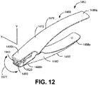
- the second example hand tool 1450 comprises a second example hand held tool mount or handle assembly 1460 shown oriented in a y-axis or first plane.
- Handle assembly 1460 which is sized for hand manipulation or grasping by the user, comprises an upper handle member 1470 that includes a generally smooth, contoured, arcuate-shaped upper shell 1472 that matingly covers an arcuate-shaped upper frame member 1475.
- Upper frame member 1475 has a proximal end portion 1477a and a distal end portion 1477b.
- Handle assembly 1460 further comprises a lower handle member 1480 that includes a generally smooth, contoured, arcuate-shaped lower shell 1482 that matingly covers an arcuate-shaped lower frame member 1484.
- Lower frame member 1484 has a proximal end portion 1485a and a distal end portion 1485b.
- Lower handle member 1480 is disposed in the first plane opposite upper handle member 1470.
- the contoured or arcuate shape of upper shell 1472 that belongs to upper handle member 1470 and the contoured or arcuate shape of lower shell 1482 that belongs to lower handle member 1480 facilitates grasping thereof by the user of hand tool 1450.
- Frame members 1475/1484 provide support for shells 1472/1482 and serve other useful functions, as described herein below.
- Upper handle member 1470 defines a proximal end portion 1486a and a distal end portion 1486b for reasons recited herein below.
- lower handle member 1480 defines a proximal end portion 1488a and a distal end portion 1488b for reasons recited herein below.
- Hand tool 1450 is also provided with a resilient biasing member in the form of a coiled torsion spring 1490 for reasons provided herein below.
- Torsion spring 1490 is disposed between upper handle member 1470 and lower handle member 1480.
- Torsion spring 1490 is configured to have a pair of protruding ends 1492a/1492b thereof in contact with upper handle member 1470 and lower handle member 1480, respectively, for providing a biasing force against upper handle member 1470 and lower handle member 1480. In this manner, torsion spring 1490 provides a biasing return force to maintain upper handle member 1470 and lower handle member 1480 in an open default position, as shown. Upper handle member 1470 and lower handle member 1480 are maintained in the open default position until the user simultaneously applies manual pressure to upper handle member 1470 and lower handle member 1480 to move upper handle member 1470 and lower handle member 1480 closer together. This act by the user places torsion spring 1490 in compression. Upon release of the manual pressure by the user, torsion spring 1490 is released from its compressed state and expands, so that handle members 1470/1480 return to their open, default positions.
- upper handle member 1470 and lower handle member 1480 are pivotably connected to each other on an axis defined by a mounting or linkage bolt 1500 (see FIG. 19 ) and are held apart from one another, in a default position, by the previously mentioned torsion spring 1490.
- Linkage bolt 1500 therefore facilitates holding the two handle members 1470/1480 pivotally together.
- torsion spring 1490 of a particular configuration is illustrated, it should be understood by those skilled in the art that other suitable biasing or spring means may be utilized, such as a coiled compression spring (not shown) or other suitable spring means.
- hand tool 1450 generally includes a tool mount or coupler assembly indicated generally at 1510.
- the coupler assembly 1510 includes an upper mount or upper coupler in the form of an articulating upper heim joint, generally referred to as 1520.
- Coupler assembly 1510 further includes a lower mount or lower coupler in the form of an articulating lower heim joint, generally referred to as 1530.
- Upper heim joint 1520 is threadably attached to distal end portion 1477b of upper frame member 1475 by means of an elongate, externally threaded upper shank portion 1540 (see FIG. 19 ) that is received in an internally threaded upper bore or hole (not shown) formed in distal end portion 1477b.
- lower heim joint 1530 is threadably attached to distal end portion 1485b of lower frame member 1484 by means of an elongate, externally threaded lower shank portion 1550 that is received in an internally threaded lower bore or hole (not shown) formed in distal end portion 1485b.
- upper shank portion 1540 is threadably received in the upper hole and lower shank portion 1550 is threadably received in the lower hole for coupling shank portions 1540/1550 to handle members 1470/1480, respectively.
- shank portions 1540/1550 and their respective holes need not be threaded; rather, shank portions 1540/1550 and their respective holes may be smooth and sized for allowing coupling of shank portions 1540/1550 to handle members 1470/1480 by means of a press-fit.
- upper heim joint 1520 comprises an annular upper casing 1560 integrally attached to upper shank portion 1540.
- Upper casing 1560 defines an opening 1565 there through for reasons provided herein below.
- upper casing 1560 may have a generally spherical interior (not shown) contoured for slidably, matingly receiving a spherical upper ball swivel 1570, such that upper ball swivel 1570 is slidably retained within upper casing 1560.
- Upper ball swivel 1570 defines a hole 1575 (see FIG.
- upper ball swivel 1570 is capable of multi-directional, slidable movement within upper casing 1560.
- upper ball swivel 1570 is capable of side-to-side, rotational, or swivel movement in the horizontal x-axis plane as illustrated by directional arrow 1577 (see FIG. 12 ).
- lower heim joint 1530 comprises an annular lower casing 1580 integrally attached to lower shank portion 1550.
- Lower casing 1580 defines an opening 1585 there through for reasons provided herein below.
- lower casing 1580 may have a generally spherical interior (not shown) contoured for slidably, matingly receiving a spherical lower ball swivel 1590, such that lower ball swivel 1590 is slidably retained within lower casing 1580.
- Lower ball swivel 1590 defines a hole 1595 (see FIG.
- lower ball swivel 1590 is capable of multi-directional, slidable movement within lower casing 1580.
- lower ball swivel 1590 is capable of side-to-side, rotational, or swivel movement in the horizontal x-axis plane, as illustrated by previously mentioned directional arrow 1577 (see FIG. 12 ).
- Lower tool member 1610 includes a hole 1625 for reasons provided herein below.
- hand tool 1450 further includes a tool head assembly, generally referred to as 1630, for clipping fingernails and toe nails of the user of hand tool 1450.
- tool head assembly 1630 which is coupled to handle assembly 1460 by means of coupler assembly 1510, is capable of operating on (i.e., clipping) the fingernails and toe nails (i.e., the work piece) of the user in response to hand manipulation of handle assembly 1460, as described in detail presently.
- tool head assembly 1630 generally includes the upper tool member or upper jaw 1600 and the lower tool member or lower jaw 1610.
- Upper tool member 1600 and lower tool member 1610 are both disposed in the y-axis plane, lower tool member 1610 being oriented opposite to and coincident with upper tool member 1600.
- Lower tool member 1610 and upper tool member 1600 are pivotably interconnected by previously mentioned pivot pin 1620 that is sized to be received in previously mentioned hole 1625, such as by a press fit.
- pivot pin 1620 that is sized to be received in previously mentioned hole 1625, such as by a press fit.
- upper tool member 1600 has an inwardly-curved first cutting edge portion 1640.
- lower tool member 1610 has an inwardly curved second cutting edge portion 1650. Fingernails and toe nails of the user are clipped or cut when cutting edge portions 1640/1650 are brought to bear against each other in the manner described hereinabove.
- a third embodiment hand or work tool 2450 which is constructed in accordance with the present invention.
- the work tool 2450 is constructed so it may be easily manipulated to operate on a work piece in a fast and convenient manner while preventing over-cutting on a work piece, such as for example, without limitation, a fingernail or a toenail.
- work tool 2450 utilizes a novel locking mechanism that substantially prevents the handle assemblies of work tool 2450 from coming disengaged, as will be discussed in greater detail later.
- distal ends of the cutting blades of work tool 2450 are prevented from extending outwardly beyond from the tool handle assemblies any further than the tool handle proximal ends PE.
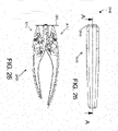
- Such motion limitation prevents the cutting blades from operating on a work piece beyond the cutting plane line CPL if the blade assemblies are aligned with respect to the tool handle assemblies, as shown in FIG. 25 , as will be discussed in greater detail later.
- the blade assemblies' axis defined by the blade assembly pivot pin and the tool handle assemblies' axis defined by the tool handle pivot pin are in alignment with one another to allow the respective blade assemblies to move in unison with pivoting handle movement of the tool handle assemblies, which in turn, allows the cutting blades of the respective blade assemblies to come into perfect alignment with the cutting line plane CLP at the end of handle travel.
- the work tool 2450 generally comprises a tool handle assembly 2460 which carries a tool head or an attack angle orientation assembly 3010 which is configured to perform a cutting operation on a work piece (not shown).
- a resilient biasing member 3050 maintains the tool handle assembly 2460 in an open default or resting position as best seen in FIG. 21 in anticipation of executing a cutting operation.
- the biasing member 3050 further causes the tool handle assembly 2460 to move from a closed or working position, as best seen in FIG. 26 , to the resting position upon the completion of a cutting operation under the biasing force of the biasing member 3050.
- the tool handle assembly 2460 moves from the open position to the working position, which in turn causes a pair of cutting blades 2640 and 2650, (each having cutting blade distal ends DE) which form part of the tool head assembly 3010, to be moved into alignment with a cutting plane indicated generally by a cutting plane line CPL, as best seen in FIGS. 25 and 26 .
- the cutting plane line CPL is a fixed imaginary line extending between the tool handle assembly proximal ends, indicated generally at PE, and the cutting blade distal ends DE at about a nip of the cutting blades 2640 and 2650 when they are closed into their cutting position as best seen in FIG. 26 .
- This limitation in positioning is an important feature of the work tool 2450 since the cutting blade distal ends DE are pulled inwardly to a position adjacent to the tool handle proximal ends PE preventing the cutting blades 2640 and 2650 from operating on a work piece significantly beyond the cutting plane line CPL if the cutting blades 2640 and 2650 are aligned with respect to work tool 2450, as shown in FIG. 25 .
- Visual and tactile feedback is also provided to a user since the user is able to see the cutting blades as they cut the work object and tactile feed is also provided by either one of the proximal ends PE of the tool handle assembly 2460 making physical contact with a body surface area adjacent to the work piece, e.g. a fingernail or a toenail for example.
- a body surface area adjacent to the work piece e.g. a fingernail or a toenail for example.
- the cutting blades 2640 and 2650 are moved about first and second orientation planes which includes rotational or swivel movement in the second orientation plane, as more particularly illustrated by directional arrows 2577, as best seen in FIG. 21 and discussed in greater detail later, then the cutting blades 2640 and 2650 may be capable of operating on a work piece significantly beyond the cutting plane line CPL.
- the tool handle assembly 2460 generally includes an upper tool handle assembly 3012 and a lower tool handle assembly 3014.
- the upper tool handle assembly 3012 and the lower tool handle assembly 3014 are configured to be snap-fit together to enable their pivotal movement relative to one another in a first orientation plane.
- Tool handle assembly 2460 is sized for hand manipulation or grasping by a user (not shown). When snap-fit together, as best seen if FIG.
- the upper tool handle assembly 3012 and the lower tool handle assembly 3014 become pivotally connected on an axis defined by a pivot cylinder or pivot pin 2559 and a pin receiving saddle structure or pivot cylinder connector structure 2574A and 2574BA and 2574A and 2574BB, as best seen in FIG. 23 .
- a pin receiving saddle structure or pivot cylinder connector structures 2574A and 2574B receives and retains the pivot pin 2559.
- the pivot cylinder connector structures 2574A and 2574B therefor in combination with the pivot pin 2559 secure the upper tool handle assembly 3012 and the lower tool handle assembly 3014 removably pivotally together.
- the pivot pin 2559 accidentally becomes removed from the pin receiving saddle structures 2574A and 2574B, the upper tool handle assembly 3012 and the lower tool handle assembly 3014 may become accidentally separated by the work tool 2450 being accidentally subjected to a strong impact force, for example by the work tool 2450 accidentally falling from the hand of a user and striking the ground or a stationary flat surface, such as a table.
- the work tool 2450 is provided with a locking mechanism 2660 that permanently locks together the upper tool handle assembly 3012 and the lower tool handle assembly 301.
- the locking mechanism 2660 makes it virtually impossible for these assemblies 3012 and 3014 to be separated from one another even if the work tool 2450 is subjected to a sudden and unexpected impact force.
- the upper tool handle assembly 3012 generally includes an upper handle member 2470 having a distal end portion 2486a and a proximal end portion 2486b.
- the upper tool handle member 2470 is provided with an outer shell-like structure 2472A having a generally smooth contoured, arcuate shape, and a preformed inner structure 2472B with structural features that will be described hereinafter in greater detail which facilitate the attachment of those component parts and assemblies required to form the complete upper tool handle assembly 3012.
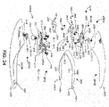
- the component parts and assemblies forming the complete upper tool handle assembly 3012 generally include an upper coupler assembly indicated generally at 2510 and an upper blade assembly 2645 which is carried by the upper coupler assembly 2510.
- the upper blade assembly 2645 is moveable about first and second orientation planes which includes rotational or swivel movement in the second orientation plane, as more particularly illustrated by directional arrows 2577, as best seen in FIG. 21 , and in and out movements in the first orientation plane which movements are relative to the proximal end (PE) of the upper handle member 2470.
- the preformed inner structure 2472B is configured with a biasing member retaining slot 3064 which is disposed at about the distal end 2486b of the upper handle member 2470.
- the retaining slot 3064 is configured to receive and retain in place an up-turned protruding end 3060A of a distal end portion 3060 of the biasing member 3050.
- the inner structure 2472B of the upper handle member 2470 is further configured with a set of upstanding screw receiving members, such as an upstanding screw receiving member 4010, as best seen in FIG. 23 .
- the screw receiving members 4010 act as anchoring locations for a set of coupler screws 2560 and 2562, respectively, which pass through upper coupler openings 2553 and 2554, respectively, in order to secure the upper coupler assembly 2510 to the inner structure 2472B of the upper handle member 2470.
- the inner structure 2472B of the upper handle member 2470 further includes a spring receiving recess indicated generally at SR, as best seen in FIG. 23 .
- the spring receiving recess SR is dimensioned for receiving therein in a loose-fit a compression spring 2558 which forms part of an upper orientation mechanism 2550A that will be described hereinafter in greater detail.
- the upper coupler assembly 2510 is configured to carry the upper orientation mechanism 2550A which, in turn, is configured to be coupled to the upper blade assembly 2645 that will be described hereinafter in greater detail.
- the upper coupler assembly 2510 is also configured to be fixed securely to the inner structure 2472B of the upper tool handle member 2470, as earlier described.
- the upper coupler assembly 2510 is provided with an upper bracket 2551.
- the upper bracket 2551 is provided with bracket mounting holes 2553 and 2554, as previously described, along with an opening 2552 having a generally spherical contoured wall structure that functions as a socket for receiving therein a spherical shaped upper swivel ball 2555.
- the upper ball 2555 is slidably mounted within socket opening 2552.
- the upper orientation mechanism 2550A incudes a spring loaded upper buffer arrangement 3030A, as best seen in FIG. 23 .
- the spring loaded upper buffer arrangement 3030A is interposed between the upper handle member 2470 and the upper ball 2555 such that the upper ball 2555 is held within the socket opening 2552.
- the upper buffer arrangement 3030A generally includes an upper handle compression spring 2558 and an upper ball swivel buffer 2557.
- the upper ball swivel buffer 2557 is provided with a generally spherical contoured centrally disposed recess area 2557A that is dimensioned to receive therein a top portion of the upper ball 2555.
- the opposite side of the upper ball swivel buffer 2557 is provided with an upstanding spring receiving post 2557P which is dimensioned to receive and retain thereon the upper handle compression spring 2558.
- the post 2557P is also dimensioned to be received within the spring receiving recess SR, as best seen in FIG. 24 .
- the spring receiving recess SR is dimensioned for receiving therein the compression spring 2558 as mounted on the post 2557P.
- the compression spring 2558 exerts a downwardly directed compression force on the buffer 2557, which interacts with the upper ball 2555 to provide a constant friction on the upper ball 2555 as upper ball 2555 interacts with upper blade assembly 2645 so that upper blade assembly 2645 does not excessively move around.
- the upper ball 2555 is provided with an integrally connected threaded shank 2556 which is dimensioned to be threadably attached within a threaded opening 2648 disposed in the upper blade assembly 2645.
- the proximal ends PE of the respective handle members 2470 and 2480 separate from one another ( FIG. 26 ).
- the blade assembly 2645 is pulled by its non-blade bearing end upwardly pivoting about a pivot pin 2620 to allow the upper blade 2650 to move in an opposite direction downwardly to make contact with the lower blade 2640.
- the blades 2640 and 2650 make contact when they come into alignment precisely with each other to cut a work object imposed between the blades 2640 and 2650, respectively.
- the lower blade assembly 2630 and its associated blade 2640 are interconnected to the lower handle member 2480 in substantially the same manner as the upper blade assembly 2645 to impart a force to move the lower blade 2640 toward the upper blade 2650 to cut the work object imposed between the blades 2640 and 2650, respectively.
- shank 2556 has been described as having a threaded end that is received within a threaded hole 2648 of the upper blade assembly 2645, it should be understood by those skilled in the art, that the threaded shank 2556 and its respective shank receiving threaded hole 2648 need not be threaded. Rather, each of these components 2556 and 2648 may be smooth and sized for allowing coupling of the shank to the upper blade assembly by means of a friction-tight fit.
- the upper coupler assembly 2510 is also provided with a V-shaped protuberance 3102 which is configured to be received within a V-shaped saddle like structure 3104 of lower coupler assembly 2570 extending perpendicularly upward from the base of a bracket 2571 forming part of the lower coupler assembly 2570.
- V-shaped protuberance 3102 is received within the V-shaped saddle like structure 3104.
- the pivot pin 2559 may now be inserted into pin receiving saddle structure or pivot cylinder connector structures 2574A and 2574B of the lower coupler assembly 2570 to further secure the upper coupler assembly 2510 to the lower coupler assembly 2570 enabling the upper and lower tool handle assemblies 3012 and 3014 to pivot in response to a user applying simultaneous manual pressure to the upper and lower tool handle assemblies 3012 and 3014.
- the upper cutting blade assembly 2645 includes at its proximal end upper cutting blade 2650 which has an inwardly-curved structure to enable cutting alignment with the lower cutting blade 2640. Located at the distal end of the cutting blade assembly 2645 is the opening 2648 for receiving shank 2556, as discussed earlier.
- the upper hinge opening 2646 is located along a mid-portion of upper cutting blade assembly 2645, as discussed earlier. As discussed above, upper hinge opening 2646 and lower hinge opening 2632 interact with pivot pin 2620 to enable the upper blade assembly 2645 and the lower blade assembly 2630 to pivot in unison with the pivoting motions of the upper tool handle assembly 3012 and the lower tool handle assembly 3014.
- the upper blade assembly 2645 is configured to be pivotally mounted for rectilinear movement in a y-axis orientation, as well as simultaneous movement in an x-axis orientation in order to enable at least one of the cutting blades 2640 and 2650 to come into alignment with each other.
- the various two plane motions of the upper cutting blade assembly 2645 are made possible by the upper orientation mechanism 2550 that will be described shortly.
- the upper blade assembly 2645 and the lower blade assembly 2630 align such that the individual blade structures form an aligned axis defined by a pair of pin holes 2646 and 2632, respectively.
- These pin holes 2646 and 2632 are dimensioned for receiving therein a pivot pin 2620, as best seen in FIGS. 23-25 , that enables the upper blade assembly 2645 and the lower blade assembly 2630 to pivot in unison with the pivoting motions of the upper tool handle assembly 3012 and the lower tool handle assembly 3014.
- blade assembly axis defined by pivot pin 2620 and the tool handle assemblies axis defined by the pivot pin 2559 are in alignment with one another, as best seen in FIGS. 23 and 25 .
- the upper orientation mechanism 2550A is described hereinafter as being configured as a multi-directional coupler such as a ball and socket type arrangement.
- upper ball 2555 travels about within the socket opening 2552.
- the upper ball 2555 is provided with an integrally connected threaded shank 2556.
- the threaded portion of the shank 2556 is threadably attached to the threaded opening 2648 disposed in the upper blade assembly 2645.
- the placement of the upper ball within the socket opening 2552 and the connection between the upper ball 2555 and the upper blade assembly 2645 allow upper blade assembly 2645 to be moveable about first and second orientation planes which includes rotational or swivel movement in the second orientation plane and in and out movements in the first orientation plane.
- the biasing member 3050 in a first embodiment is a leaf spring 3051.
- the leaf spring 3051 is generally U-shaped having a proximal end apex like structure 3052 with a pair of substantially straight leg members 3054 and 3056, respectively.
- the straight leg members 3054 and 3056 extend away from each other commencing at the apex 3052 each terminating at respective ones of their distal ends indicated generally at 3060 and 3062.
- Each respective distal end 3060 and 3062 is provided with an up-turned protruding end, and more specifically protruding ends 3060A and 3062A.
- the protruding ends 3060A and 3062A are configured to be received in respective ones of the tool assembly biasing member retaining slots 3064 and 3066, respectively.
- the biasing member 3050 provides a biasing return force to maintain or retain the upper tool handle assembly 3012 and the lower tool handle assembly 3014 in their open default or resting position, as best seen in FIGS. 21 and 23 .
- the upper tool handle assembly 3012 and the lower tool handle assembly 3014 when assembled together forming the work tool 2450, which are maintained in the above-mentioned open default or resting position.
- the resting position of the work tool 2450 is maintained until the user applies manual pressure simultaneously to upper tool handle assembly 3012 and lower tool handle assembly 3014 to move them closer together.
- This act by the user places leaf spring 3051 in compression.
- leaf spring 3051 Upon release of the manual pressure applied by the user, leaf spring 3051 is freed or released from its compressed state and expands, so that the upper tool handle assembly 3012 and the lower tool handle assembly 3014 return to their default positions.
- biasing member 3050 has been described herein in a leaf spring 3051 configuration, it should be understood by those skilled in the art that other suitable biasing means may be utilized, such as a coiled compression spring, a compressible bar and other types and kinds of spring means.
- the locking mechanism assembly 2660 is configured to secure the upper tool handle assembly 3012 and the lower handle assembly 3014 together to facilitate their pivotal movement enabling movement between open and closed positions.
- the locking mechanism assembly 2660 generally includes a cylinder pin 2559 which is received in the V-shaped protuberance 3102 forming part of the upper coupler assembly 2510 and the previously mentioned pin receiving saddle structures 2574A and 2574B located on V-shaped saddle like structure 3104 forming part of the lower coupler assembly 2570.
- the working tool 2450 is provided with a second locking mechanism that includes a locking pin 2661 which is received within a space 3106A located at a mid-portion of the V-shaped protuberance 3102 and a space 3106B which is located at a mid-portion of V-shaped saddle like structure 3104.
- a second locking mechanism that includes a locking pin 2661 which is received within a space 3106A located at a mid-portion of the V-shaped protuberance 3102 and a space 3106B which is located at a mid-portion of V-shaped saddle like structure 3104.
- locking pin 2661 includes a distal end catch 2664, a proximal end stop 2662, and a shank portion 2663.
- Located on upper bracket 2551 are two protuberances 3108A and 3108B.
- the locking pin 2661 is received between the upper tool handle assembly 3012 and the lower tool handle assembly 3014 such that distal end catch 2664 is positioned in locking engagement with protuberance 3108A; proximal end stop 2662 is brought into locking engagement with protuberance 3108B; and shank portion 2663 contacts an upper portion of cylinder pin 2559.
- locking pin 2661 is slid through the aligned openings 3106A and 3106B and across the top of cylinder pin 2559 until distal end catch 2664 is brought into locking engagement with protuberance 3108A and proximal end stop 2662 is positioned in locking engagement with protuberance 3108B so that shank portion 2663 contacts the top of cylinder pin 2559 in order to further retain cylinder pin 2559 within the pivot cylinder connector structures 2574A and 2574B.
- upper tool handle assembly 3012 and the lower tool handle assembly 3014 are permanently secured together in cooperation with the cylinder pin 2559/pin receiving saddle structure or pivot cylinder connector structures 2574A and 2574B and locking pin 2660.
- the two structures may be swiveled back and forth in order to bring the cutting blades 2640 and 2650 into a desired cutting angle.
- the work tool 2450 is capable of universal movement to reach a desired cutting angle for cutting a work object.
- the lower tool handle assembly 3014 generally includes a lower handle member 2480 having a distal end portion 2488a and a proximal end portion 2488b.
- the lower tool handle member 2480 is provided with an outer shell-like structure 2482A having a generally smooth contoured, arcuate shape, and a preformed inner structure 2482B with structural features that will be described hereinafter in greater detail which facilitate the attachment of those component parts and assemblies required to form the complete lower tool handle assembly 3014.
- the component parts and assemblies forming the complete lower tool handle assembly 3014 generally include a lower coupler assembly indicated generally at 2570 and a lower blade assembly 2630 which is carried by the lower coupler assembly 2570.
- the lower blade assembly 2630 is moveable about first and second orientation planes which includes rotational or swivel movement in the second orientation plane, as more particularly illustrated by directional arrows 2577, as best seen in FIG. 21 , and in and out movements in the first orientation plane which in and out movements are relative to the proximal end (PE) of the lower handle member 2480.
- the preformed inner structure 2482B is configured with a biasing member retaining slot 3066 which is disposed at about the distal end 2488b of the lower handle member 2480.
- the retaining slot 3066 is configured to receive and retain in place an up-turned protruding end 3062A of a distal end portion 3062 of the biasing member 3050.
- the inner structure 2482B of the lower handle member 2480 is further configured with a set of upstanding screw receiving members, such as an upstanding screw receiving member 4010, as best seen in FIG. 23 .
- the screw receiving members 4010 act as anchoring locations for a lower coupler screw 2580 which passes through a lower coupler opening (not shown) and a set of lower coupler screws 2582 which pass through lower coupler openings 2573 in order to secure the lower coupler assembly 2570 to the inner structure 2482B of the lower handle member 2480.
- the inner structure 2482B of the lower handle member 2480 further includes a spring receiving recess indicated generally at SR, as best seen in FIG. 23 .
- the spring receiving recess SR is dimensioned for receiving therein in a snug-fit a compression spring 2578 which forms part of a lower orientation mechanism 2550B that will be described hereinafter in greater detail.
- the lower coupler assembly 2570 is configured to carry the lower orientation mechanism 2550B which, in turn, is configured to be coupled to the lower blade assembly 2630 that will be described hereinafter in greater detail.
- the lower coupler assembly 2570 is also configured to be fixed securely to the inner structure 2482B of the lower tool handle member 2470, as earlier described.
- the lower coupler assembly 2570 is provided with a lower bracket 2571.
- the lower bracket 2571 is provided with bracket mounting holes 2573, as previously described, along with an opening 2572 having a generally spherical contoured wall structure that functions as a socket for receiving therein a spherical shaped lower swivel ball 2575.
- the lower ball 2575 is slidably mounted within socket opening 2572.
- the lower orientation mechanism 2550B incudes a spring loaded lower buffer arrangement 3030B, as best seen in FIG. 23 .
- the spring loaded lower buffer arrangement 3030B is interposed between the lower handle member 2480 and the lower ball 2575 such that the lower ball 2575 is held within the socket opening 2572.
- the lower buffer arrangement 3030B generally includes a lower handle compression spring 2578 and a lower ball swivel buffer 2577.
- the lower ball swivel buffer 2577 is provided with a generally spherical contoured centrally disposed recess area 2777A that is dimensioned to receive therein a top portion of the lower ball 2575.
- the opposite side of the lower ball swivel buffer 2577 is provided with an upstanding spring receiving post 2577P which is dimensioned to receive and retain thereon the lower handle compression spring 2578.
- the post 2577P is also dimensioned to be received within the spring receiving recess SR, as best seen in FIG. 23 .
- the spring receiving recess SR is dimensioned for receiving therein the compression spring 2578 as mounted on the post 2577P.
- the compression spring 2578 exerts an upwardly directed compression force to the buffer 2577, which interacts with the lower ball 2575 to provide a constant friction on the lower ball 2575 as lower ball 2575 interacts with lower blade assembly 2630 so that lower blade assembly 2630 does not excessively move around.
- the lower ball 2575 is provided with an integrally connected threaded shank 2576 which is dimensioned to be threadably attached within a threaded opening 2634 disposed in the lower blade assembly 2630.
- shank 2576 has been described as having a threaded end that is received within a threaded hole 2634 of the lower blade assembly 2630, it should be understood by those skilled in the art, that the threaded shank 2576 and its respective shank receiving threaded hole 2634 need not be threaded. Rather, each of these components 2576 and 2634 may be smooth and sized for allowing coupling of the shank to the upper blade assembly by means of a friction-tight fit.
- the lower blade assembly 2630 includes at its distal end a lower cutting blade 2640 which has an inwardly-curved structure to enable cutting alignment with the upper cutting blade 2650.
- Located at the proximal end of the cutting blade assembly 2630 is the threaded opening 2634 for receiving the threaded portion of shank 2576, as discussed earlier.
- the lower hinge opening 2632 is located along a mid-portion of lower blade assembly 2630, as discussed earlier.
- upper hinge opening 2646 and lower hinge opening 2632 interact with pivot pin 2620 to enable the upper blade assembly 2645 and the lower blade assembly 2630 to pivot in unison with the pivoting motions of the upper tool handle assembly 3012 and the lower tool handle assembly 3014.
- the lower orientation mechanism 2550B is described hereinafter as being configured as a multi-directional coupler such as a ball and socket type arrangement.
- a multi-directional coupler such as a ball and socket type arrangement.
- other types and kinds or orientation mechanism are clearly contemplated by the present invention and the description of the ball and socket type of orientation mechanism that follow is for example only and should not be consider a limitation on the present invention.
- lower ball 2575 travels about within the socket opening 2572.
- the lower ball 2575 is provided with an integrally connected threaded shank 2576.
- the threaded portion of the shank 2576 is threadably attached to the threaded opening 2634 disposed in the lower blade assembly 2630.
- the placement of the lower ball 2575 within the socket opening 2572 and the connection between the lower ball 2575 and the lower blade assembly 2630 allow lower blade assembly 2630 to be moveable about first and second orientation planes which includes rotational or swivel movement in the second orientation plane and in and out movements in the first orientation plane.
- an illustrative method not according to the invention, generally referred to as 1660, is provided for manufacturing a hand tool.
- the method starts at a step 1670.
- a handle assembly is provided.
- a tool head assembly is coupled to the handle assembly.
- the handle assembly and the tool head assembly are interconnected to at least one heim joint coupler.
- the method stops at a step 1710.
- handle assembly 1010 belonging to the first example hand tool 1000 may be coupled to a hydraulic system that is, in turn, hand actuated.
- a hydraulic system would be coupled to upper handle member 1020 and lower handle 1030 for hydraulically operating upper and lower handle members 1020/1030.
- handle assembly 1010 may be coupled to an electric motor system that is, in turn, hand operated by means of a suitable guidance control switch.
- Such an electric motor system would be coupled to upper handle member 1020 and lower handle member 1030 for electrically operating upper and lower handle members 1020/1030 and for articulating the tool head assembly by means of electric motors.
Landscapes
- Engineering & Computer Science (AREA)
- Mechanical Engineering (AREA)
- Life Sciences & Earth Sciences (AREA)
- Forests & Forestry (AREA)
- Scissors And Nippers (AREA)
Description
- This invention generally relates to tools and more particularly relates to hand tools and work tools.
- Conventional hand tools, such as conventional fingernail and toe nail clippers, have proven problematic to use, particularly when used by the elderly, arthritic individuals, stroke victims and others who have limited range of arm, wrist and hand movement.
- More specifically, conventional fingernail and toe nail clippers have a spring handle that pivots about a fulcrum. Connected to the handle is a lever that is configured to downwardly press against the handle, so as to cause cutting edges formed on the handle to contact each other. However, the handle and lever must be in alignment with each other during the nail clipping operation to achieve efficient operation of the device.
- Movement of the handle and lever into alignment during the nail clipping operation requires extensive manipulation of the handle and lever and extensive dexterity on the part of the user. Such extensive manipulation and need for extensive dexterity is problematic for elderly persons, arthritic individuals, stroke victims and others having limited arm, wrist and hand movement.
- As another example, with respect to surgical instruments, it is often necessary to perform surgery on difficult-to-reach areas of the human body without obstructing the surgeon's field of view. This is also true with respect to veterinarians who perform surgery on animals. Also, in the specific case of surgery, it is also often necessary for the surgeon to use one surgical instrument, such as scissors, to perform a clipping/cutting procedure on a body structure, while using another surgical instrument, such as forceps or clamps, to hold the body structure. These two surgical instruments typically have significantly different fixed configurations. Having to stock a multiplicity of surgical instruments in hospital inventory with significantly different fixed configurations for performing different surgical functions is inconvenient and costly.
- As a further example, with respect to wire and bolt cutters, it is sometimes necessary to sever cables and bolts located in confined spaces and recesses. This may be necessary when performing machinery repair, remodeling/renovating buildings, rescue of persons trapped by fallen building structure and debris, and rescue of persons trapped in damaged automobiles due to a collision. Use of cable and bolt cutters having configurations with cutting edges in a permanent, fixed orientation can make such cutting operations more difficult.
- Attempts have been made to address the considerations mentioned hereinabove with respect to the structure and use of hand tools. For example,
U.S. Pat. No. 5,062,666 titled "Nail Clipper" issued Nov. 12, 1991, in the name of Jaw-Shiunn Tsay relates to an improved nail clipper. - According to the Tsay patent, the nail clipper comprises an elongate lever, a short upper body, a long lower body and a joint pin to assemble the lever and both the upper and the lower bodies together at their front sections, so that the lever can be pressed down to compress the upper body downward on the lower body. The nail clipper further comprises two opposed pairs of curved cutting edges provided on opposite sides of the upper and the lower bodies (see
FIGS. 3 ,4 ,5 and6 of the Tsay patent). The cutting edges are fixed at two positions, one position being perpendicular to the other position. This patent states that an advantage of the nail clipper is that the two pairs of cutting edges can easily clip nails on the other hand after finishing one hand. - However, the Tsay patent discloses that the cutting edges are fixed at two positions, one position being perpendicular to the other position. Fixing the cutting edges at two positions may nonetheless require a user to extensively manipulate the nail clipper to clip nails. Requiring the user to extensively manipulate the nail clipper to clip nails is inconvenient for the user.
- Another attempt to address the considerations mentioned hereinabove with respect to the structure and use of hand tools is disclosed in
U.S. Pat. No. 3,742,957 titled "Surgical Clamp" issued July 3, 1973, in the name of Jack H. White. The White patent relates to surgical and like clamps. - According to the White patent, a clamp includes a set of jaws including a gripping portion and an actuating portion and pin means pivotally connecting the jaws for movement between open and closed positions within a first plane. A set of handles comprising crank arms are disposed and operable between the open and closed positions within a second plane. The second plane is mutually intersecting with the first plane and the crank arms are connected to the actuating portion of the jaws at the junctures of respective leg portions of the crank arms. As mentioned in the White patent, this connection comprises a hinge for infinite angular positioning of the first plane containing the jaws with respect to the second plane containing the crank arms. Also, the leg portions of the crank arms are pivotally joined by a pin, which in the illustrated embodiment comprises a screw, to provide for opening and closing movement of the handles.
- However, the White patent discloses that opening and closing movement of the handles is accomplished by adjustment of a screw (i.e., pin) that joins the handles. Only allowing opening and closing movement of the handles by means of a screw creates unnecessary delay in adjusting the clamp before surgery, readjusting the clamp during surgery, if necessary, and releasing the clamp after surgery because a screw driver is apparently needed to adjust the screw. Such a delay before, during and after a surgical procedure is undesirable.
- Another attempt to address the considerations mentioned hereinabove with respect to the structure and use of hand tools is disclosed in
U.S. Pat. No. 2,020,242 titled "Swivel Head Tool" issued Nov. 5, 1935, in the name of G. W. Geddes. The Geddes patent relates to tools in which the jaws may be placed in various angular positions relative to an operating handle system. - According to the Geddes patent, a bolt clipper embodying a jaw lever system and an actuating handle lever system are provided. The jaw levers can be adjusted to various angular positions relative to the plane of the handle levers so as to permit operating swinging movement of the jaws. For this purpose, joints embodying mating spherical surfaces and tail portions of the jaw levers are provided with shallow recesses of spherical contour, which receive interposed balls on which at least of one of the parts turns (see column 2, lines 15-37 of the Geddes patent). This patent also discloses that handle members are apparently pivotally mounted by means of a screw-like pin.
- Although the Geddes patent discloses handle members that are pivotally mounted, this patent apparently requires adjustment of a screw-like pin in order to return the handle members to their default position. Requiring adjustment of the screw-like pin in order to return the handle members to their default position is inconvenient for the user because a screw driver is apparently needed to adjust the screw-like pin.
-
US 2014/0041195 discloses a hand tool and method of manufacturing and using the same. The hand tool includes a tool mount including at least one heim joint that removably receives thereon a tool head assembly. The heim joint and tool head assembly cooperate to provide the hand tool with a multi-directional, variable angle of attack on a work piece in a manner that accommodates aged, arthritic and otherwise handicapped people having a limited range of arm, wrist and hand movement. DocumentUS 2014/0041 195 shows a hand tool according to the preamble ofclaims 1 and 4. - Although the approaches recited hereinabove disclose various configurations of hand tools, the approaches recited hereinabove do not appear to disclose the invention described and claimed herein below.
- A tool according to the invention is disclosed in the independent claims. The different embodiments of the invention are given in the dependent claims.
- The foregoing is a summary and thus may contain simplifications, generalizations, inclusions, and/or omissions of detail. Consequently, those skilled in the art will appreciate that the summary is illustrative only and is not intended to be in any way limiting. In addition to the illustrative aspects, embodiments, and features described hereinabove, further aspects, embodiments, and features will become apparent by reference to the drawings and the following detailed description.
- The invention will be more fully understood by reference to the detailed description in conjunction with the following figures, wherein:
-
FIG. 1 is a view in perspective of a first example hand tool, not according to the invention, including a first example tool head assembly, not according to the invention, configured as a fingernail or toe nail clipper; -
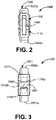
FIG. 2 is a rear view in elevation of the first example hand tool; -
FIG. 3 is a front view in elevation of the first example hand tool; -
FIG. 4 is a right side view in elevation of the first example hand tool; -
FIG. 4A is a fragmentary view in elevation of the right side of the first example hand tool; -
FIG. 5 is a left side view in elevation of the first example hand tool, the first example hand tool being shown in an open position; -
FIG. 5A is a left side view in elevation of the first example hand tool, the first example hand tool being shown in a closed position; -
FIG. 6 is a partially exploded view of the first example hand tool; -
FIG. 7 is a top plan view of the first example hand tool; -
FIG. 8 is a bottom plan view of the first example hand tool; -
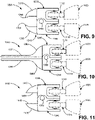
FIG. 9 is a right side view in elevation of a detached first example tool head assembly configured as a fingernail or toe nail clipper; -
FIG. 10 is a right side view in elevation of a detached second example tool head assembly, not according to the invention, configured as a surgical clamp; -
FIG. 11 is a right side view in elevation of a detached third example tool head assembly, not according to the invention, configured as a cable/bolt cutter; -
FIG. 12 is a view in perspective of a second example hand tool, not according to the invention, including a tool head assembly configured as a fingernail or toe nail clipper, the second embodiment hand tool being shown in an open position; -
FIG. 13 is a front view in elevation of the second example hand tool; -
FIG. 14 is a rear view in elevation of the second example hand tool; -
FIG. 15 is a right side view in elevation of the second example hand tool; -
FIG. 16 is a left side view in elevation of the second example hand tool; -
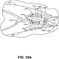
FIG. 16A is a fragmentary view in elevation of a distal end portion of the second example hand tool; -
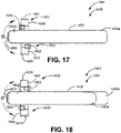
FIG. 17 is a top plan view of the second example hand tool; -
FIG. 18 is a bottom plan view of the second example hand tool; -
FIG. 18A is a view in elevation of the second example hand tool in a closed position; -
FIG. 19 is an exploded view of the second example hand tool; -
FIG. 20 is a flowchart showing an illustrative method, not according to the invention, of manufacturing the first and second embodiments of the hand tool; -
FIG. 21 is a view in perspective of a third embodiment work tool, which is constructed in accordance with the present invention; -
FIG. 22 is a top plan view of the third embodiment work tool; -
FIG. 23 is a cross-sectional view of the work tool ofFIG. 22 taken along line A-A, illustrating the blade assembly in an open position; -
FIG. 24 is an exploded view of the third embodiment work tool; -
FIG. 25 is a top plan view of the work tool; and -
FIG. 26 is a cross-sectional view of the work tool ofFIG. 25 taken along line A-A, illustrating the blade assembly in a closed position. - In addition, the present patent specification uses outline headings for clarity of presentation. However, it is to be understood that the outline headings are for presentation purposes, and that different types of subject matter may be discussed throughout the application (e.g., device(s)/structure(s) may be described under process(es)/operations heading(s) and/or process(es)/operations may be discussed under structure(s)/process(es) headings; and/or descriptions of single topics may span two or more topic headings). Hence, the use of the outline headings is not intended to be in any way limiting.
- Therefore, with reference to
FIGS. 1 ,2 and 3 , there is shown a first embodiment hand tool, generally referred as 1000, for operating on a work piece (not shown). In the exemplary embodiment illustrated,hand tool 1000 is a fingernail or toe nail clipper for clipping or cutting fingernails and toe nails of a user (also not shown). However, it will be appreciated thathand tool 1000 is not limited to the configuration of a fingernail or toe nail clipper. Rather,hand tool 1000 may be in the configuration of other types of hand tools, as well, such as clamps and bolt cutters. - Referring again to
FIGS. 1 ,2 and 3 ,hand tool 1000 comprises a first embodiment hand held tool mount or handleassembly 1010 shown oriented in a y-axis or first plane.Handle assembly 1010, which is sized for hand manipulation or grasping by the user, includes a generally smooth, contoured, arcuate-shapedupper handle member 1020 and a generally smooth, contoured, arcuate-shapedlower handle member 1030 disposed in the first plane oppositeupper handle member 1020. The contoured or arcuate shape ofupper handle member 1020 andlower handle member 1030 facilitates grasping thereof by the user ofhand tool 1000.Upper handle member 1020 defines aproximal end portion 1032a and adistal end portion 1032b for reasons recited herein below. Similarly,lower handle member 1030 defines aproximal end portion 1035a and adistal end portion 1035b for reasons recited herein below. Thehandle assembly 1010 is also provided with a resilient biasing member in the form of anelongate leaf spring 1040 for reasons provided herein below. In this regard,leaf spring 1040 has a unitary construction that includes a centralstraight segment portion 1050, which is disposed between an upperstraight portion 1050a and a lower rounded orcurved end portion 1050b. Upperstraight portion 1050a is positioned generally intermediateproximal end portion 1032a anddistal end portion 1032b ofupper handle member 1020. Lower rounded orcurved end portion 1050b is positioned generally intermediateproximal end portion 1035a anddistal end portion 1035b oflower handle member 1030. - Still referring to
FIGS. 1 ,2 and 3 , in order to hold thehandle members 1020/1030 apart, lower rounded orcurved end portion 1050b ofleaf spring 1040 is mounted within a lowerhandle member cutout 1060 by a mounting or spring pin indicated generally at 1070.Cutout 1060 is disposed at an inner rearward surface area oflower handle member 1030 in a manner that allowsleaf spring 1040 to be disposed at an inclined angle betweenupper handle member 1020 andlower handle member 1030. The opposite end ofleaf spring 1040, which terminates in upperstraight portion 1050a, permits the opposite or upperstraight portion 1050a to rest in engagement with an inner surface area ofupper handle member 1020. In short,leaf spring 1040 is wedged betweenupper handle member 1020 andlower handle member 1030 to provide a return force when the twohandle members 1020/1030 are manually squeezed together by the user, such as in the direction ofdirectional arrows FIG. 5A ). - Referring again to
FIGS. 1 ,2, and 3 ,upper handle member 1020 andlower handle member 1030 are pivotably connected to each other on an axis defined by a mounting orlinkage bolt 1080 and are held apart from one another, in a default position, by the previously mentionedleaf spring 1040.Linkage bolt 1080 therefore facilitates holding the twohandle members 1020/1030 pivotally together. The previously mentioned return force is a force sufficient to cause the twohandle members 1020/1030 to move pivotally away from one another about the axis defined by mounting orlinkage bolt 1080 whenhandle members 1020/1030 are released by the user, so thathandle members 1020/1030 return to their default or open positions as best seen inFIG. 1 . Althoughleaf spring 1040 of a particular configuration is illustrated, it should be understood by those skilled in the art that other suitable biasing or spring means may be utilized, such as a coiled compression spring (not shown) or other suitable spring means. - As shown in
FIGS. 1 ,2 and 3 ,hand tool 1000 further includes a heim joint coupler assembly indicated generally at 1090. Thecoupler assembly 1090 includes an upper mount or upper coupler in the form of an articulating upper heim joint 1100.Coupler assembly 1090 further includes a lower mount or lower coupler in the form of an articulating lower heim joint 1110. Upper heim joint 1100 is threadably attached todistal end portion 1032b ofupper handle member 1020 by means of an elongate, externally threadedupper shank portion 1120 that is received in an internally threaded upper bore orhole 1130 formed indistal end portion 1032b. Similarly, lower heim joint 1110 is threadably attached todistal end portion 1035b oflower handle member 1030 by means of an elongate, externally threadedlower shank portion 1140 that is received in an internally threaded lower bore orhole 1150 formed indistal end portion 1035b. Thus,upper shank portion 1120 is threadably received inupper hole 1130 andlower shank portion 1140 is threadably received inlower hole 1150 for couplingshank portions 1120/1140 to handlemembers 1020/1030, respectively. However,shank portions 1120/1140 andholes 1130/1150 need not be threaded; rather,shank portions 1120/1140 andholes 1130/1150 may be smooth and sized for allowing coupling ofshank portions 1120/1140 to handlemembers 1020/1030 by means of a press-fit. - Referring to
FIGS. 1 ,4 ,4A ,5 ,5A and6 , upper heim joint 1100 comprises an annularupper casing 1160 integrally attached toupper shank portion 1120.Upper casing 1160 defines anopening 1165 there through for reasons provided herein below. In addition,upper casing 1160 may have a generally spherical interior (not shown) contoured for slidably, matingly receiving a sphericalupper ball swivel 1170, such thatupper ball swivel 1170 is slidably retained withinupper casing 1160.Upper ball swivel 1170 defines an upper ball hole 1180 (seeFIG. 6 ) centrally there through for reasons provided herein below. In this manner,upper ball swivel 1170 is capable of multi-directional, slidable movement withinupper casing 1160. In other words,upper ball swivel 1170 is capable of side-to-side, rotational, or swivel movement in the horizontal x-axis plane as illustrated by directional arrow 1182 (seeFIG. 1 ). In addition,upper ball swivel 1170 is capable of tilting movement in the y-axis plane as illustrated by directional arrow 1184 (seeFIGS. 1 and5A ) as well as tilting movement in the x-axis plane as illustrated by directional arrow 1186 (seeFIG. 1 ). - Referring again to
FIGS. 1 ,4 ,4A ,5 ,5A and6 , lower heim joint 1110 comprises ar annularlower casing 1190 integrally attached tolower shank portion 1140.Lower casing 1190 defines alower casing opening 1195 there through for reasons provided herein below. In addition,lower casing 1190 may have a generally spherical interior (not shown) contoured for slidably, matingly receiving sphericallower ball swivel 1200, such thatlower ball swivel 1200 is slidably retained withinlower casing 1190.Lower ball swivel 1200 defines a lower ball hole 1210 (seeFIG. 6 ) centrally there through for reasons provided herein below. In this manner,lower ball swivel 1200 is capable of multi-directional, slidable movement withinlower casing 1190. In other words,lower ball swivel 1200 is capable of side-to-side, rotational, or swivel movement in the horizontal x-axis plane as illustrated by previously mentioned directional arrow 1182 (seeFIG. 1 ). In addition,lower ball swivel 1200 is capable of tilting movement in the y-axis plane as illustrated by directional arrow 1205 (seeFIGS. 1 and5A ) as well as tilting movement in the x-axis plane as illustrated by previously mentioned directional arrow 1186 (seeFIG. 1 ). As described fully herein below, it will be appreciated that ball swivels 1170/1200 will rotate and tilt in unison as will be explained in greater detail hereinafter. - Referring to
FIGS. 1 ,3 ,4 ,4A ,5 ,5A and6 , to providehand tool 1000 with the functionality noted hereinabove,hand tool 1000 further includes a replaceable, first example tool head assembly, generally referred to as 1220, not according to the invention, for clipping fingernails and toe nails of the user ofhand tool 1000. In other words,tool head assembly 1220, which is coupled to handleassembly 1010 by means ofcoupler assembly 1090, is capable of operating on (i.e., clipping) the fingernails and toe nails (i.e., the work piece) of the user in response to hand manipulation ofhandle assembly 1010, as described in detail presently. In this regard,tool head assembly 1220 generally includes anupper tool member 1230 and alower tool member 1240 both disposed in the y-axis plane,lower tool member 1240 being oriented opposite to and coincident withupper tool member 1230.Lower tool member 1240 includes a lower toolmember pivoting portion 1250a andupper tool member 1230 includes an upper toolmember pivoting portion 1250b (seeFIG. 3 ). The lower toolmember pivoting portion 1250a and upper toolmember pivoting portion 1250b are pivotably interconnected by apivot pin 1260. Thus, the pivotable interconnection offirst pivoting portion 1250a andsecond pivoting portion 1250b allowlower tool member 1240 andupper tool member 1230 to pivot aboutpivot pin 1260 for reasons provided herein below. - Referring yet again to
FIGS. 1 ,4 ,4A ,5 ,5A and6 ,upper tool member 1230 has a unitary construction and includes anupper jaw 1270 in the form of an upper blade tool having an upper tool elongate frontcutting edge portion 1280. Similarly,lower tool member 1240 has a unitary construction and includes alower jaw 1290 oppositeupper jaw 1270. Thelower jaw 1290 is in the form of a lower blade tool having a lower tool elongate frontcutting edge portion 1300. Fingernails and toe nails of the user are clipped or cut when cuttingedge portions 1280/1300 are brought to bear against each in the manner described herein below. - Still referring to
FIGS. 1 ,4 ,4A ,5 ,5A and6 ,upper tool member 1230 includes anupper arm portion 1304a and alower arm portion 1304b.Lower arm portion 1304b is disposed opposite of and coincident withupper arm portion 1304a.Upper arm portion 1304a defines an internally threadedupper arm bore 1306a there through andlower arm portion 1304b defines an internally threadedlower arm bore 1306b there through (seeFIG. 4A ),upper arm bore 1306a andlower arm bore 1306b are aligned with previously mentionedupper ball hole 1180 defined by theupper ball swivel 1170. Similarly,lower tool member 1240 includes a third or anotherupper arm portion 1308a and a fourth or anotherlower arm portion 1308b. The lower tool memberlower arm portion 1308b is disposed opposite of and coincident with the lower tool memberupper arm portion 1308a. The lower toolupper arm portion 1308a defines an internally threaded lower toolupper arm bore 1309a there through and lower toollower arm portion 1308b defines an internally threaded lower toollower arm bore 1309b there through (seeFIG. 4A ). The lower toollower arm bore 1309a and the lower toolupper arm bore 1309b are aligned with previously mentionedlower ball hole 1210 defined bylower ball swivel 1200. Moreover,upper arm portion 1304a andlower arm portion 1304b of theupper tool member 1230 are spaced apart, so as to define aspace 1310 there between for receiving upper heim joint 1100 there into. Similarly,upper arm portion 1308a andlower arm portion 1308b of thelower tool member 1240 are spaced apart, so as to define anotherspace 1320 there between for receiving lower heim joint 1110 there into.Spaces heim joints 1100/1110 therein and allowtool head assembly 1220 to freely rotate in the x-axis plane without obstruction. In this regard, it will be appreciated by those skilled in the art that ball swivels 1170/1200 will rotate and tilt in unison and to a like extent due to their interconnection by means of theupper tool member 1230, thelower tool member 1240 and the pivot pin 1260 (seeFIGS. 1 ,4 ,4A ,5 and5A ). - Although not critical, it is nonetheless important that
tool head assembly 1220 be detachably coupled tocoupler assembly 1090, so that different types oftool head assemblies 1220 and various sizes of the same type oftool head assembly 1220 can be interchanged. Also, providing for detachment oftool head assembly 1220 fromcoupler assembly 1090 allows replacement of a worntool head assembly 1220. Thus,hand tool 1000 is versatile and accommodates tool head assemblies required for different applications. - Referring again to
FIGS. 1 ,4 ,4A ,5 ,5A and6 , the manner in whichtool head assembly 1220 is detachably coupled tocoupler assembly 1090 will now be described. In this regard, an upper connecting member, such as externally threaded upper tool screw-bolt 1330 (seeFIG. 6 ), is caused to threadably engage internally threadedupper arm bore 1306a and internally threadedlower arm bore 1306b as upper tool screw-bolt 1330 extends throughupper arm bore 1306a,upper ball hole 1180 defined byupper ball swivel 1170 and intolower arm bore 1306b. In this manner, upper heim joint 1100 is retained withinspace 1310 asupper tool member 1230 rotates and/or tilts. - Similarly, a lower connecting member, such as externally threaded lower tool screw-
bolt 1340, is caused to threadably engage internally threadedlower arm bore 1309b and internally threadedupper arm bore 1309a as lower tool screw-bolt 1340 extends throughupper arm bore 1309b,lower ball hole 1210 defined bylower ball swivel 1200 and intoupper arm bore 1309a. In this manner, lower heim joint 1110 is retained withinspace 1320 aslower tool member 1240 rotates and/or tilts. Also, in this manner,upper tool member 1230 andlower tool member 1240 are detachably coupled to upper heim joint 1100 and lower heim joint 1110, respectively, due to use ofscrew bolts 1330/1340. It should be appreciated thatupper tool member 1230 andlower tool member 1240 will rotate and tilt in unison and to a like extent due to their interconnection by means ofpivot pin 1260 and due to use of upper screw-bolt 1330 and lower screw-bolt 1340, as described hereinabove. Detaching or decoupling ofupper tool member 1230 andlower tool member 1240 from upper heim joint 1100 and lower heim joint 1110, respectively, is accomplished by reversing the above-described steps for couplingupper tool member 1230 andlower tool member 1240 to upper heim joint 1100 and lower heim joint 1110. - As previously indicated, movement of
tool head assembly 1220 is multi-directional becausetool head assembly 1220 is adapted to rotate or swivel in the x-axis plane and tilt in both the x-axis and y-axis planes. Such rotation and tilting is provided by presence ofupper ball swivel 1170 that belongs to upper heim joint 1100 andlower ball swivel 1200 that belongs to lower heim joint 1110. However, for the sake of brevity, the description herein below is directed only to rotation or swiveling oftool head assembly 1220 in the x-axis plane, it being understood thattool head assembly 1220 is adapted to swivel and tilt in the x-axis plane and only tilt in the y-axis plane. - Therefore, referring to
FIGS. 1 ,7 and8 ,tool head assembly 1220 is adapted to move side-to-side (i.e., rotate or swivel) in the x-axis plane to a user selected angle less than or equal to an angle theta "O" of about 180° degrees.Tool head assembly 1220 is capable of rotating in the x-axis plane due to presence ofupper ball swivel 1170 andlower ball swivel 1200, as previously mentioned. Such side-to-side, rotational or swiveling movement oftool head assembly 1220 in the x-axis plane is accomplished by hand. - Turning now to
FIGS. 9, 10 and 11 , various tool head assembly examples are there shown, not according to the invention. As previously mentioned, detachable first exampletool head assembly 1220 comprisesupper jaw 1270 having upper toolfront cutting edge 1280 andlower jaw 1290 having lower toolfront cutting edge 1300 for cutting or clipping fingernails or toe nails of the user when uppertool cutting edge 1280 and lower toolfront cutting edge 1300 are brought to bear against each other. - A detachable second example tool head assembly, not according to the invention generally referred to as 1350, comprises an
upper jaw 1360 having an upperjaw clamping extension 1370 and alower jaw 1380 having a lowerjaw clamping extension 1390.Upper jaw 1360 andlower jaw 1380 of second exampletool head assembly 1350 are capable of pivoting aboutpivot pin 1260 in a manner substantially similar to the pivoting action ofupper jaw 1270 andlower jaw 1290 of firstexample tool head 1220. Upperjaw clamping extension 1370 and lowerjaw clamping extension 1390 are capable of capturing and holding a work piece (not shown) there between, such as tissue being operated upon during a surgical procedure. - A detachable third example tool head assembly, not according to the invention, generally referred to as 1400, comprises an
upper jaw 1410 having an upper sharpenededge 1420 and alower jaw 1430 having a lower sharpenededge 1440.Upper jaw 1410 andlower jaw 1430 of second exampletool head assembly 1440 are capable of pivoting aboutpivot pin 1260 in a manner substantially similar to the pivoting action ofupper jaw 1270 andlower jaw 1290 of firstexample tool head 1220. Upper sharpenededge 1420 and lower sharpenededge 1440 are capable of shearing a work piece (not shown) there between, such as a bolt or cable. - Turning now to
FIGS. 12 ,13 and 14 , there is shown a second example hand tool, not according to the invention, generally referred to as 1450. The secondexample hand tool 1450, not according to the invention, comprises a second example hand held tool mount or handleassembly 1460 shown oriented in a y-axis or first plane.Handle assembly 1460, which is sized for hand manipulation or grasping by the user, comprises anupper handle member 1470 that includes a generally smooth, contoured, arcuate-shapedupper shell 1472 that matingly covers an arcuate-shaped upper frame member 1475. Upper frame member 1475 has aproximal end portion 1477a and adistal end portion 1477b.Handle assembly 1460 further comprises alower handle member 1480 that includes a generally smooth, contoured, arcuate-shapedlower shell 1482 that matingly covers an arcuate-shapedlower frame member 1484.Lower frame member 1484 has aproximal end portion 1485a and adistal end portion 1485b.Lower handle member 1480 is disposed in the first plane oppositeupper handle member 1470. The contoured or arcuate shape ofupper shell 1472 that belongs toupper handle member 1470 and the contoured or arcuate shape oflower shell 1482 that belongs to lowerhandle member 1480 facilitates grasping thereof by the user ofhand tool 1450. Frame members 1475/1484 provide support forshells 1472/1482 and serve other useful functions, as described herein below.Upper handle member 1470 defines aproximal end portion 1486a and adistal end portion 1486b for reasons recited herein below. Similarly,lower handle member 1480 defines aproximal end portion 1488a and adistal end portion 1488b for reasons recited herein below.Hand tool 1450 is also provided with a resilient biasing member in the form of a coiledtorsion spring 1490 for reasons provided herein below.Torsion spring 1490 is disposed betweenupper handle member 1470 andlower handle member 1480.Torsion spring 1490 is configured to have a pair of protruding ends 1492a/1492b thereof in contact withupper handle member 1470 andlower handle member 1480, respectively, for providing a biasing force againstupper handle member 1470 andlower handle member 1480. In this manner,torsion spring 1490 provides a biasing return force to maintainupper handle member 1470 andlower handle member 1480 in an open default position, as shown.Upper handle member 1470 andlower handle member 1480 are maintained in the open default position until the user simultaneously applies manual pressure toupper handle member 1470 andlower handle member 1480 to moveupper handle member 1470 andlower handle member 1480 closer together. This act by the user placestorsion spring 1490 in compression. Upon release of the manual pressure by the user,torsion spring 1490 is released from its compressed state and expands, so thathandle members 1470/1480 return to their open, default positions. - Referring again to
FIGS. 12 ,13 and 14 ,upper handle member 1470 andlower handle member 1480 are pivotably connected to each other on an axis defined by a mounting or linkage bolt 1500 (seeFIG. 19 ) and are held apart from one another, in a default position, by the previously mentionedtorsion spring 1490.Linkage bolt 1500 therefore facilitates holding the twohandle members 1470/1480 pivotally together. Althoughtorsion spring 1490 of a particular configuration is illustrated, it should be understood by those skilled in the art that other suitable biasing or spring means may be utilized, such as a coiled compression spring (not shown) or other suitable spring means. - Referring to
FIGS. 15 and 16 ,hand tool 1450 generally includes a tool mount or coupler assembly indicated generally at 1510. Thecoupler assembly 1510 includes an upper mount or upper coupler in the form of an articulating upper heim joint, generally referred to as 1520.Coupler assembly 1510 further includes a lower mount or lower coupler in the form of an articulating lower heim joint, generally referred to as 1530. Upper heim joint 1520 is threadably attached todistal end portion 1477b of upper frame member 1475 by means of an elongate, externally threaded upper shank portion 1540 (seeFIG. 19 ) that is received in an internally threaded upper bore or hole (not shown) formed indistal end portion 1477b. Similarly, lower heim joint 1530 is threadably attached todistal end portion 1485b oflower frame member 1484 by means of an elongate, externally threaded lower shank portion 1550 that is received in an internally threaded lower bore or hole (not shown) formed indistal end portion 1485b. Thus,upper shank portion 1540 is threadably received in the upper hole and lower shank portion 1550 is threadably received in the lower hole for couplingshank portions 1540/1550 to handlemembers 1470/1480, respectively. However,shank portions 1540/1550 and their respective holes need not be threaded; rather,shank portions 1540/1550 and their respective holes may be smooth and sized for allowing coupling ofshank portions 1540/1550 to handlemembers 1470/1480 by means of a press-fit. - Referring to
FIGS. 15, 16 ,17, 18 and19 , upper heim joint 1520 comprises an annularupper casing 1560 integrally attached toupper shank portion 1540.Upper casing 1560 defines anopening 1565 there through for reasons provided herein below. In addition,upper casing 1560 may have a generally spherical interior (not shown) contoured for slidably, matingly receiving a sphericalupper ball swivel 1570, such thatupper ball swivel 1570 is slidably retained withinupper casing 1560.Upper ball swivel 1570 defines a hole 1575 (seeFIG. 19 ) centrally there through for receiving a smoothupper connector pin 1576 about whichupper ball swivel 1570 freely rotates in the x-plane.Connector pin 1576 also interconnectsupper ball swivel 1570 to upper frame member 1475 and to anupper tool member 1600 as will be explained hereinafter in greater detail. In this manner,upper ball swivel 1570 is capable of multi-directional, slidable movement withinupper casing 1560. In other words,upper ball swivel 1570 is capable of side-to-side, rotational, or swivel movement in the horizontal x-axis plane as illustrated by directional arrow 1577 (seeFIG. 12 ). - Referring again to
FIGS. 15, 16 ,17, 18 and19 , lower heim joint 1530 comprises an annularlower casing 1580 integrally attached to lower shank portion 1550.Lower casing 1580 defines anopening 1585 there through for reasons provided herein below. In addition,lower casing 1580 may have a generally spherical interior (not shown) contoured for slidably, matingly receiving a sphericallower ball swivel 1590, such thatlower ball swivel 1590 is slidably retained withinlower casing 1580.Lower ball swivel 1590 defines a hole 1595 (seeFIG. 19 ) centrally there through for receiving a smoothlower connector pin 1596 about whichlower ball swivel 1590 freely rotates in the x-plane.Connector pin 1596 also interconnectslower ball swivel 1590 tolower frame member 1484 and to alower tool member 1610, as will be explained hereinafter in greater detail. In this manner,lower ball swivel 1590 is capable of multi-directional, slidable movement withinlower casing 1580. In other words,lower ball swivel 1590 is capable of side-to-side, rotational, or swivel movement in the horizontal x-axis plane, as illustrated by previously mentioned directional arrow 1577 (seeFIG. 12 ). As described fully herein below, it will be appreciated that ball swivels 1570/1590 will rotate in unison and to a like extent due to their interconnection by means of theupper tool member 1600, thelower tool member 1610 and a pivot pin 1620 (seeFIGS. 12 ,15 ,16 and19 ).Lower tool member 1610 includes ahole 1625 for reasons provided herein below. - Still referring to
FIGS. 15, 16 ,17, 18 and19 , to providehand tool 1450 with the functionality noted hereinabove,hand tool 1450 further includes a tool head assembly, generally referred to as 1630, for clipping fingernails and toe nails of the user ofhand tool 1450. In other words,tool head assembly 1630, which is coupled to handleassembly 1460 by means ofcoupler assembly 1510, is capable of operating on (i.e., clipping) the fingernails and toe nails (i.e., the work piece) of the user in response to hand manipulation ofhandle assembly 1460, as described in detail presently. In this regard,tool head assembly 1630 generally includes the upper tool member orupper jaw 1600 and the lower tool member orlower jaw 1610.Upper tool member 1600 andlower tool member 1610 are both disposed in the y-axis plane,lower tool member 1610 being oriented opposite to and coincident withupper tool member 1600.Lower tool member 1610 andupper tool member 1600 are pivotably interconnected by previously mentionedpivot pin 1620 that is sized to be received in previously mentionedhole 1625, such as by a press fit. Thus, the pivotable interconnection oflower tool member 1610 andupper tool member 1600 allowlower tool member 1610 andupper tool member 1600 to pivot aboutpivot pin 1620. - Referring again to
FIGS. 15, 16 ,17, 18 and19 ,upper tool member 1600 has an inwardly-curved firstcutting edge portion 1640. Similarly,lower tool member 1610 has an inwardly curved secondcutting edge portion 1650. Fingernails and toe nails of the user are clipped or cut when cuttingedge portions 1640/1650 are brought to bear against each other in the manner described hereinabove. - Referring now to the drawings and more particularly to
FIGS. 21-25 , there is illustrated a third embodiment hand orwork tool 2450 which is constructed in accordance with the present invention. As will be explained hereinafter in greater detail, thework tool 2450 is constructed so it may be easily manipulated to operate on a work piece in a fast and convenient manner while preventing over-cutting on a work piece, such as for example, without limitation, a fingernail or a toenail. Also,work tool 2450 utilizes a novel locking mechanism that substantially prevents the handle assemblies ofwork tool 2450 from coming disengaged, as will be discussed in greater detail later. Further, the distal ends of the cutting blades ofwork tool 2450 are prevented from extending outwardly beyond from the tool handle assemblies any further than the tool handle proximal ends PE. Such motion limitation prevents the cutting blades from operating on a work piece beyond the cutting plane line CPL if the blade assemblies are aligned with respect to the tool handle assemblies, as shown inFIG. 25 , as will be discussed in greater detail later. Finally, the blade assemblies' axis defined by the blade assembly pivot pin and the tool handle assemblies' axis defined by the tool handle pivot pin are in alignment with one another to allow the respective blade assemblies to move in unison with pivoting handle movement of the tool handle assemblies, which in turn, allows the cutting blades of the respective blade assemblies to come into perfect alignment with the cutting line plane CLP at the end of handle travel. - Considering now the
work tool 2450 in greater detail with reference toFIGS. 21-25 , thework tool 2450 generally comprises atool handle assembly 2460 which carries a tool head or an attackangle orientation assembly 3010 which is configured to perform a cutting operation on a work piece (not shown). Aresilient biasing member 3050 maintains thetool handle assembly 2460 in an open default or resting position as best seen inFIG. 21 in anticipation of executing a cutting operation. The biasingmember 3050 further causes thetool handle assembly 2460 to move from a closed or working position, as best seen inFIG. 26 , to the resting position upon the completion of a cutting operation under the biasing force of the biasingmember 3050. - As will be explained hereinafter in greater detail, if the
cutting blades FIG. 25 , when manipulated by a user, thetool handle assembly 2460 moves from the open position to the working position, which in turn causes a pair ofcutting blades tool head assembly 3010, to be moved into alignment with a cutting plane indicated generally by a cutting plane line CPL, as best seen inFIGS. 25 and 26 . The cutting plane line CPL is a fixed imaginary line extending between the tool handle assembly proximal ends, indicated generally at PE, and the cutting blade distal ends DE at about a nip of thecutting blades FIG. 26 . This limitation in positioning is an important feature of thework tool 2450 since the cutting blade distal ends DE are pulled inwardly to a position adjacent to the tool handle proximal ends PE preventing thecutting blades cutting blades work tool 2450, as shown inFIG. 25 . Visual and tactile feedback is also provided to a user since the user is able to see the cutting blades as they cut the work object and tactile feed is also provided by either one of the proximal ends PE of thetool handle assembly 2460 making physical contact with a body surface area adjacent to the work piece, e.g. a fingernail or a toenail for example. It is to be understood that if thecutting blades directional arrows 2577, as best seen inFIG. 21 and discussed in greater detail later, then thecutting blades - Considering now the
tool handle assembly 2460 in greater detail with reference toFIGS. 21-24 , thetool handle assembly 2460 generally includes an uppertool handle assembly 3012 and a lowertool handle assembly 3014. The uppertool handle assembly 3012 and the lowertool handle assembly 3014 are configured to be snap-fit together to enable their pivotal movement relative to one another in a first orientation plane.Tool handle assembly 2460 is sized for hand manipulation or grasping by a user (not shown). When snap-fit together, as best seen ifFIG. 21 , the uppertool handle assembly 3012 and the lowertool handle assembly 3014 become pivotally connected on an axis defined by a pivot cylinder orpivot pin 2559 and a pin receiving saddle structure or pivotcylinder connector structure 2574A and 2574BA and 2574A and 2574BB, as best seen inFIG. 23 . - As will be explained hereinafter in greater detail, a pin receiving saddle structure or pivot
cylinder connector structures pivot pin 2559. The pivotcylinder connector structures pivot pin 2559 secure the uppertool handle assembly 3012 and the lowertool handle assembly 3014 removably pivotally together. In this regard, if thepivot pin 2559 accidentally becomes removed from the pin receivingsaddle structures tool handle assembly 3012 and the lowertool handle assembly 3014 may become accidentally separated by thework tool 2450 being accidentally subjected to a strong impact force, for example by thework tool 2450 accidentally falling from the hand of a user and striking the ground or a stationary flat surface, such as a table. As will be explained hereinafter in greater detail, to prevent such accidental separation, thework tool 2450 is provided with alocking mechanism 2660 that permanently locks together the uppertool handle assembly 3012 and the lower tool handle assembly 301. In this regard, thelocking mechanism 2660 makes it virtually impossible for theseassemblies work tool 2450 is subjected to a sudden and unexpected impact force. - Considering now the upper
tool handle assembly 3012 in greater detail with reference toFIGS. 21-24 , the uppertool handle assembly 3012 generally includes anupper handle member 2470 having adistal end portion 2486a and aproximal end portion 2486b. The uppertool handle member 2470 is provided with an outer shell-like structure 2472A having a generally smooth contoured, arcuate shape, and a preformedinner structure 2472B with structural features that will be described hereinafter in greater detail which facilitate the attachment of those component parts and assemblies required to form the complete uppertool handle assembly 3012. - The component parts and assemblies forming the complete upper
tool handle assembly 3012 generally include an upper coupler assembly indicated generally at 2510 and anupper blade assembly 2645 which is carried by theupper coupler assembly 2510. Theupper blade assembly 2645, as will be explained hereinafter in greater detail, is moveable about first and second orientation planes which includes rotational or swivel movement in the second orientation plane, as more particularly illustrated bydirectional arrows 2577, as best seen inFIG. 21 , and in and out movements in the first orientation plane which movements are relative to the proximal end (PE) of theupper handle member 2470. - Considering now the
upper handle member 2470 in greater detail, the preformedinner structure 2472B is configured with a biasingmember retaining slot 3064 which is disposed at about thedistal end 2486b of theupper handle member 2470. As will be explained hereinafter in greater detail, the retainingslot 3064 is configured to receive and retain in place an up-turnedprotruding end 3060A of adistal end portion 3060 of the biasingmember 3050. - The
inner structure 2472B of theupper handle member 2470 is further configured with a set of upstanding screw receiving members, such as an upstandingscrew receiving member 4010, as best seen inFIG. 23 . Thescrew receiving members 4010 act as anchoring locations for a set ofcoupler screws upper coupler openings upper coupler assembly 2510 to theinner structure 2472B of theupper handle member 2470. - The
inner structure 2472B of theupper handle member 2470 further includes a spring receiving recess indicated generally at SR, as best seen inFIG. 23 . The spring receiving recess SR is dimensioned for receiving therein in a loose-fit acompression spring 2558 which forms part of anupper orientation mechanism 2550A that will be described hereinafter in greater detail. - Considering now the
upper coupler assembly 2510 in greater detail with reference toFIGS. 23-25 , theupper coupler assembly 2510 is configured to carry theupper orientation mechanism 2550A which, in turn, is configured to be coupled to theupper blade assembly 2645 that will be described hereinafter in greater detail. Theupper coupler assembly 2510 is also configured to be fixed securely to theinner structure 2472B of the uppertool handle member 2470, as earlier described. - In order to enable the
upper coupler assembly 2510 to carry theupper orientation mechanism 2550A, theupper coupler assembly 2510 is provided with anupper bracket 2551. Theupper bracket 2551 is provided withbracket mounting holes opening 2552 having a generally spherical contoured wall structure that functions as a socket for receiving therein a spherical shapedupper swivel ball 2555. In this regard, theupper ball 2555 is slidably mounted withinsocket opening 2552. - In order to retain the
upper ball 2555 within thesocket opening 2552, theupper orientation mechanism 2550A incudes a spring loadedupper buffer arrangement 3030A, as best seen inFIG. 23 . The spring loadedupper buffer arrangement 3030A is interposed between theupper handle member 2470 and theupper ball 2555 such that theupper ball 2555 is held within thesocket opening 2552. To enable this retaining action, theupper buffer arrangement 3030A generally includes an upperhandle compression spring 2558 and an upperball swivel buffer 2557. The upperball swivel buffer 2557 is provided with a generally spherical contoured centrally disposedrecess area 2557A that is dimensioned to receive therein a top portion of theupper ball 2555. The opposite side of the upperball swivel buffer 2557 is provided with an upstandingspring receiving post 2557P which is dimensioned to receive and retain thereon the upperhandle compression spring 2558. Thepost 2557P is also dimensioned to be received within the spring receiving recess SR, as best seen inFIG. 24 . In this regard, the spring receiving recess SR is dimensioned for receiving therein thecompression spring 2558 as mounted on thepost 2557P. In thisarrangement 3030A, thecompression spring 2558 exerts a downwardly directed compression force on thebuffer 2557, which interacts with theupper ball 2555 to provide a constant friction on theupper ball 2555 asupper ball 2555 interacts withupper blade assembly 2645 so thatupper blade assembly 2645 does not excessively move around. - In order to impart the above-mentioned swivel action to the
upper blade assembly 2645, theupper ball 2555 is provided with an integrally connected threadedshank 2556 which is dimensioned to be threadably attached within a threadedopening 2648 disposed in theupper blade assembly 2645. In this arrangement, as theupper handle member 2470 is moved towards thelower handle member 2480, the proximal ends PE of therespective handle members FIG. 26 ). When the uppertool handle assembly 3012 and lowertool handle assembly 3014 pivot theblade assembly 2645 is pulled by its non-blade bearing end upwardly pivoting about apivot pin 2620 to allow theupper blade 2650 to move in an opposite direction downwardly to make contact with thelower blade 2640. As noted earlier, theblades blades - It should be understood by those skilled in the art, that the
lower blade assembly 2630 and its associatedblade 2640 are interconnected to thelower handle member 2480 in substantially the same manner as theupper blade assembly 2645 to impart a force to move thelower blade 2640 toward theupper blade 2650 to cut the work object imposed between theblades - Although the
shank 2556 has been described as having a threaded end that is received within a threadedhole 2648 of theupper blade assembly 2645, it should be understood by those skilled in the art, that the threadedshank 2556 and its respective shank receiving threadedhole 2648 need not be threaded. Rather, each of thesecomponents - The
upper coupler assembly 2510 is also provided with a V-shapedprotuberance 3102 which is configured to be received within a V-shaped saddle likestructure 3104 oflower coupler assembly 2570 extending perpendicularly upward from the base of abracket 2571 forming part of thelower coupler assembly 2570. In this regard, when the uppertool handle assembly 3012 and the lowertool handle assembly 3014 are snap-fit together, the V-shapedprotuberance 3102 is received within the V-shaped saddle likestructure 3104. Thepivot pin 2559 may now be inserted into pin receiving saddle structure or pivotcylinder connector structures lower coupler assembly 2570 to further secure theupper coupler assembly 2510 to thelower coupler assembly 2570 enabling the upper and lowertool handle assemblies tool handle assemblies - Considering now the
upper blade assembly 2645 in greater detail with reference toFIGS. 23-25 , the uppercutting blade assembly 2645 includes at its proximal endupper cutting blade 2650 which has an inwardly-curved structure to enable cutting alignment with thelower cutting blade 2640. Located at the distal end of thecutting blade assembly 2645 is theopening 2648 for receivingshank 2556, as discussed earlier. Theupper hinge opening 2646 is located along a mid-portion of uppercutting blade assembly 2645, as discussed earlier. As discussed above,upper hinge opening 2646 andlower hinge opening 2632 interact withpivot pin 2620 to enable theupper blade assembly 2645 and thelower blade assembly 2630 to pivot in unison with the pivoting motions of the uppertool handle assembly 3012 and the lowertool handle assembly 3014. - The
upper blade assembly 2645 is configured to be pivotally mounted for rectilinear movement in a y-axis orientation, as well as simultaneous movement in an x-axis orientation in order to enable at least one of thecutting blades - The various two plane motions of the upper
cutting blade assembly 2645 are made possible by the upper orientation mechanism 2550 that will be described shortly. For now, it should be mentioned that when the uppertool handle assembly 3012 and the lowertool handle assembly 3014 are snap-fit together and secured for pivotal movement, theupper blade assembly 2645 and thelower blade assembly 2630 align such that the individual blade structures form an aligned axis defined by a pair ofpin holes pivot pin 2620, as best seen inFIGS. 23-25 , that enables theupper blade assembly 2645 and thelower blade assembly 2630 to pivot in unison with the pivoting motions of the uppertool handle assembly 3012 and the lowertool handle assembly 3014. It should be further noted that the blade assembly axis defined bypivot pin 2620 and the tool handle assemblies axis defined by thepivot pin 2559 are in alignment with one another, as best seen inFIGS. 23 and25 . This is an important feature of the present invention as it allows therespective blade assemblies cutting blades respective blade assemblies - Considering now the
upper orientation mechanism 2550A in greater detail with reference toFIGS. 23-25 , theupper orientation mechanism 2550A is described hereinafter as being configured as a multi-directional coupler such as a ball and socket type arrangement. - As discussed above, in order to impart the swivel action of
upper orientation mechanism 2550A,upper ball 2555 travels about within thesocket opening 2552. Also, as discussed above, theupper ball 2555 is provided with an integrally connected threadedshank 2556. The threaded portion of theshank 2556 is threadably attached to the threadedopening 2648 disposed in theupper blade assembly 2645. The placement of the upper ball within thesocket opening 2552 and the connection between theupper ball 2555 and theupper blade assembly 2645 allowupper blade assembly 2645 to be moveable about first and second orientation planes which includes rotational or swivel movement in the second orientation plane and in and out movements in the first orientation plane. - Considering now the biasing
member 3050 in greater detail with reference toFIGS. 23-25 , the biasingmember 3050 in a first embodiment is aleaf spring 3051. Theleaf spring 3051 is generally U-shaped having a proximal end apex likestructure 3052 with a pair of substantiallystraight leg members straight leg members distal end member retaining slots member 3050 provides a biasing return force to maintain or retain the uppertool handle assembly 3012 and the lowertool handle assembly 3014 in their open default or resting position, as best seen inFIGS. 21 and23 . - In use, the upper
tool handle assembly 3012 and the lowertool handle assembly 3014, when assembled together forming thework tool 2450, which are maintained in the above-mentioned open default or resting position. The resting position of thework tool 2450 is maintained until the user applies manual pressure simultaneously to uppertool handle assembly 3012 and lowertool handle assembly 3014 to move them closer together. This act by the user placesleaf spring 3051 in compression. Upon release of the manual pressure applied by the user,leaf spring 3051 is freed or released from its compressed state and expands, so that the uppertool handle assembly 3012 and the lowertool handle assembly 3014 return to their default positions. - Although the biasing
member 3050 has been described herein in aleaf spring 3051 configuration, it should be understood by those skilled in the art that other suitable biasing means may be utilized, such as a coiled compression spring, a compressible bar and other types and kinds of spring means. - Considering now the
locking mechanism assembly 2660 in greater detail with reference toFIGS. 23-25 , thelocking mechanism assembly 2660 is configured to secure the uppertool handle assembly 3012 and thelower handle assembly 3014 together to facilitate their pivotal movement enabling movement between open and closed positions. In this regard, thelocking mechanism assembly 2660 generally includes acylinder pin 2559 which is received in the V-shapedprotuberance 3102 forming part of theupper coupler assembly 2510 and the previously mentioned pin receivingsaddle structures structure 3104 forming part of thelower coupler assembly 2570. It should be understood by those skilled in the art that when the uppertool handle assembly 3012 and the lowertool handle assembly 3014 are press fit together, the respective V-shapedprotuberance 3102 and the V-shaped saddle likestructure 3104 come into alignment with one another. Thecylinder pin 2559 is then press fit into the pin receivingsaddle structures tool handle assembly 3012 and the lowertool handle assembly 3014. - As best seen in
FIGS. 23-24 , the workingtool 2450 is provided with a second locking mechanism that includes alocking pin 2661 which is received within aspace 3106A located at a mid-portion of the V-shapedprotuberance 3102 and aspace 3106B which is located at a mid-portion of V-shaped saddle likestructure 3104. It is to be understood that, as discussed above, when uppertool handle assembly 3012 and the lowertool handle assembly 3014 are press fit together, V-shapedprotuberance 3102 and the V-shaped saddle likestructure 3104 are then aligned with each other. This alignment of V-shapedprotuberance 3102 and the V-shaped saddle likestructure 3104 allowsspaces spaces locking pin 2661 is received. - As shown in
FIGS. 23 and24 , lockingpin 2661 includes adistal end catch 2664, aproximal end stop 2662, and ashank portion 2663. Located onupper bracket 2551 are twoprotuberances FIG. 23 , in order to provide the second locking mechanism arrangement between uppertool handle assembly 3012 and the lowertool handle assembly 3014, thelocking pin 2661 is received between the uppertool handle assembly 3012 and the lowertool handle assembly 3014 such thatdistal end catch 2664 is positioned in locking engagement withprotuberance 3108A;proximal end stop 2662 is brought into locking engagement withprotuberance 3108B; andshank portion 2663 contacts an upper portion ofcylinder pin 2559. - In order to provide the second locking mechanism arrangement between upper
tool handle assembly 3012 and the lowertool handle assembly 3014, lockingpin 2661 is slid through the alignedopenings cylinder pin 2559 untildistal end catch 2664 is brought into locking engagement withprotuberance 3108A andproximal end stop 2662 is positioned in locking engagement withprotuberance 3108B so thatshank portion 2663 contacts the top ofcylinder pin 2559 in order to further retaincylinder pin 2559 within the pivotcylinder connector structures tool handle assembly 3012 and the lowertool handle assembly 3014 are permanently secured together in cooperation with thecylinder pin 2559/pin receiving saddle structure or pivotcylinder connector structures pin 2660. With both the uppertool handle assembly 3012 and the lowertool handle assembly 3014 permanently secured together, the two structures may be swiveled back and forth in order to bring thecutting blades work tool 2450 is capable of universal movement to reach a desired cutting angle for cutting a work object. - Considering now the lower
tool handle assembly 3014 in greater detail with reference toFIGS. 21-24 , the lowertool handle assembly 3014 generally includes alower handle member 2480 having adistal end portion 2488a and aproximal end portion 2488b. The lowertool handle member 2480 is provided with an outer shell-like structure 2482A having a generally smooth contoured, arcuate shape, and a preformedinner structure 2482B with structural features that will be described hereinafter in greater detail which facilitate the attachment of those component parts and assemblies required to form the complete lowertool handle assembly 3014. - The component parts and assemblies forming the complete lower
tool handle assembly 3014 generally include a lower coupler assembly indicated generally at 2570 and alower blade assembly 2630 which is carried by thelower coupler assembly 2570. Thelower blade assembly 2630, as will be explained hereinafter in greater detail, is moveable about first and second orientation planes which includes rotational or swivel movement in the second orientation plane, as more particularly illustrated bydirectional arrows 2577, as best seen inFIG. 21 , and in and out movements in the first orientation plane which in and out movements are relative to the proximal end (PE) of thelower handle member 2480. - Considering now the
lower handle member 2480 in greater detail, the preformedinner structure 2482B is configured with a biasingmember retaining slot 3066 which is disposed at about thedistal end 2488b of thelower handle member 2480. As will be explained hereinafter in greater detail, the retainingslot 3066 is configured to receive and retain in place an up-turned protruding end 3062A of adistal end portion 3062 of the biasingmember 3050. - The
inner structure 2482B of thelower handle member 2480 is further configured with a set of upstanding screw receiving members, such as an upstandingscrew receiving member 4010, as best seen inFIG. 23 . Thescrew receiving members 4010 act as anchoring locations for alower coupler screw 2580 which passes through a lower coupler opening (not shown) and a set oflower coupler screws 2582 which pass throughlower coupler openings 2573 in order to secure thelower coupler assembly 2570 to theinner structure 2482B of thelower handle member 2480. - The
inner structure 2482B of thelower handle member 2480 further includes a spring receiving recess indicated generally at SR, as best seen inFIG. 23 . The spring receiving recess SR is dimensioned for receiving therein in a snug-fit acompression spring 2578 which forms part of alower orientation mechanism 2550B that will be described hereinafter in greater detail. - Considering now the
lower coupler assembly 2570 in greater detail with reference toFIGS. 23-25 , thelower coupler assembly 2570 is configured to carry thelower orientation mechanism 2550B which, in turn, is configured to be coupled to thelower blade assembly 2630 that will be described hereinafter in greater detail. Thelower coupler assembly 2570 is also configured to be fixed securely to theinner structure 2482B of the lowertool handle member 2470, as earlier described. - In order to enable the
lower coupler assembly 2570 to carry thelower orientation mechanism 2550B, thelower coupler assembly 2570 is provided with alower bracket 2571. Thelower bracket 2571 is provided withbracket mounting holes 2573, as previously described, along with anopening 2572 having a generally spherical contoured wall structure that functions as a socket for receiving therein a spherical shapedlower swivel ball 2575. In this regard, thelower ball 2575 is slidably mounted withinsocket opening 2572. In order to retain thelower ball 2575 within thesocket opening 2572, thelower orientation mechanism 2550B incudes a spring loadedlower buffer arrangement 3030B, as best seen inFIG. 23 . The spring loadedlower buffer arrangement 3030B is interposed between thelower handle member 2480 and thelower ball 2575 such that thelower ball 2575 is held within thesocket opening 2572. To enable this retaining action, thelower buffer arrangement 3030B generally includes a lowerhandle compression spring 2578 and a lowerball swivel buffer 2577. The lowerball swivel buffer 2577 is provided with a generally spherical contoured centrally disposed recess area 2777A that is dimensioned to receive therein a top portion of thelower ball 2575. The opposite side of the lowerball swivel buffer 2577 is provided with an upstandingspring receiving post 2577P which is dimensioned to receive and retain thereon the lowerhandle compression spring 2578. Thepost 2577P is also dimensioned to be received within the spring receiving recess SR, as best seen inFIG. 23 . In this regard, the spring receiving recess SR is dimensioned for receiving therein thecompression spring 2578 as mounted on thepost 2577P. In thisarrangement 3030B, thecompression spring 2578 exerts an upwardly directed compression force to thebuffer 2577, which interacts with thelower ball 2575 to provide a constant friction on thelower ball 2575 aslower ball 2575 interacts withlower blade assembly 2630 so thatlower blade assembly 2630 does not excessively move around. - In order to impart the above-mentioned swivel action to the
lower blade assembly 2630, thelower ball 2575 is provided with an integrally connected threadedshank 2576 which is dimensioned to be threadably attached within a threadedopening 2634 disposed in thelower blade assembly 2630. As discussed above, in this arrangement, as the uppertool handle assembly 3012 is moved towards the lowertool handle assembly 3014, the proximal ends PE of the respective tool handleassemblies FIG. 26 ). When the lowertool handle assembly 3014 and the uppertool handle assembly 3012 pivot thelower blade assembly 2630 is pulled by its non-blade bearing end downwardly pivoting about apivot pin 2620 to allow thelower blade 2640 to move in an opposite direction upwardly to make contact with theupper blade 2650. As noted earlier, theblades blades - Although the
shank 2576 has been described as having a threaded end that is received within a threadedhole 2634 of thelower blade assembly 2630, it should be understood by those skilled in the art, that the threadedshank 2576 and its respective shank receiving threadedhole 2634 need not be threaded. Rather, each of thesecomponents - Considering now the
lower blade assembly 2630 in greater detail with reference toFIGS. 23-25 , thelower blade assembly 2630 includes at its distal end alower cutting blade 2640 which has an inwardly-curved structure to enable cutting alignment with theupper cutting blade 2650. Located at the proximal end of thecutting blade assembly 2630 is the threadedopening 2634 for receiving the threaded portion ofshank 2576, as discussed earlier. Thelower hinge opening 2632 is located along a mid-portion oflower blade assembly 2630, as discussed earlier. As discussed above,upper hinge opening 2646 andlower hinge opening 2632 interact withpivot pin 2620 to enable theupper blade assembly 2645 and thelower blade assembly 2630 to pivot in unison with the pivoting motions of the uppertool handle assembly 3012 and the lowertool handle assembly 3014. - Considering now the
lower orientation mechanism 2550B in greater detail with reference toFIGS. 23-25 , thelower orientation mechanism 2550B is described hereinafter as being configured as a multi-directional coupler such as a ball and socket type arrangement. However other types and kinds or orientation mechanism are clearly contemplated by the present invention and the description of the ball and socket type of orientation mechanism that follow is for example only and should not be consider a limitation on the present invention. - As discussed above, in order to impart the swivel action of
lower orientation mechanism 2550B,lower ball 2575 travels about within thesocket opening 2572. Also, as discussed above, thelower ball 2575 is provided with an integrally connected threadedshank 2576. The threaded portion of theshank 2576 is threadably attached to the threadedopening 2634 disposed in thelower blade assembly 2630. The placement of thelower ball 2575 within thesocket opening 2572 and the connection between thelower ball 2575 and thelower blade assembly 2630 allowlower blade assembly 2630 to be moveable about first and second orientation planes which includes rotational or swivel movement in the second orientation plane and in and out movements in the first orientation plane. - An illustrative method, not according to the invention, associated with an example for manufacturing the hand tool will now be described.
- Referring to
FIG. 20 , an illustrative method, not according to the invention, generally referred to as 1660, is provided for manufacturing a hand tool. The method starts at astep 1670. At astep 1680, a handle assembly is provided. At astep 1690, a tool head assembly is coupled to the handle assembly. At astep 1700, the handle assembly and the tool head assembly are interconnected to at least one heim joint coupler. The method stops at astep 1710. - Other modifications and implementations will occur to those skilled in the art without departing from the scope of the invention as claimed. For example, handle
assembly 1010 belonging to the firstexample hand tool 1000, not according to the invention, may be coupled to a hydraulic system that is, in turn, hand actuated. Such a hydraulic system would be coupled toupper handle member 1020 andlower handle 1030 for hydraulically operating upper andlower handle members 1020/1030. As another example, handleassembly 1010 may be coupled to an electric motor system that is, in turn, hand operated by means of a suitable guidance control switch. Such an electric motor system would be coupled toupper handle member 1020 andlower handle member 1030 for electrically operating upper andlower handle members 1020/1030 and for articulating the tool head assembly by means of electric motors. These examples can be used for cutting bolts and cables. Accordingly, the description hereinabove is not intended to limit the invention, except as indicated in the following claims. - It is to be understood that while the invention has been described in conjunction with the detailed description thereof, the foregoing description is intended to illustrate and not limit the scope of the invention, which is defined by the scope of the appended claims. Thus, from the foregoing, it will be appreciated that, although specific embodiments of the invention have been described herein for the purpose of illustration, various modifications may be made without deviating from the scope of the invention. Other aspects, advantages, and modifications are within the scope of the following claims and the present invention is not limited except as by the appended claims.
- The specific methods and compositions described herein are representative of preferred embodiments and are exemplary and not intended as limitations on the scope of the invention. Other objects, aspects, and embodiments will occur to those skilled in the art upon consideration of this specification, and are encompassed within the scope of the claims. The invention illustratively described herein suitably may be practiced in the absence of any element or elements, or limitation or limitations, which is not specifically disclosed herein as essential. Thus, for example, in each instance herein, in embodiments or examples of the present invention, the terms "comprising", "including", "containing", etc. are to be read expansively and without limitation. The methods and processes illustratively described herein suitably may be practiced in differing orders of steps, and that they are not necessarily restricted to the orders of steps indicated herein or in the claims.
- The terms and expressions that have been employed are used as terms of description and not of limitation. It is recognized that various modifications are possible within the scope of the invention as claimed. Thus, it will be understood that although the present invention has been specifically disclosed by various embodiments and/or preferred embodiments and optional features, any and all modifications and variations of the concepts herein disclosed that may be resorted to by those skilled in the art are considered to be within the scope of this invention as defined by the appended claims.
- The invention has been described broadly and generically herein. Each of the narrower species and sub-generic groupings falling within the generic disclosure also form part of the invention. This includes the generic description of the invention with a proviso or negative limitation removing any subject matter from the genus, regardless of whether or not the excised material is specifically recited herein. Moreover, although various particular embodiments have been described, it should be appreciated that features and components from one or more such embodiment may generally be utilized in another such embodiment, whether in addition to, or instead of, features and components already present in the another embodiment, unless there are particular reasons why this cannot be done. Accordingly, the different embodiments should be seen as implementations that are independent of one another, but rather as examples of a wider range of potentially overlapping implementations.
- It is also to be understood that as used herein and in the appended claims, the singular forms "a," "an," and "the" include plural reference unless the context clearly dictates otherwise, the term "X and/or Y" means "X" or "Y" or both "X" and "Y", and the letter "s" following a noun designates both the plural and singular forms of that noun. In addition, where features or aspects of the invention are described in terms of Markush groups, it is intended and those skilled in the art will recognize, that the invention embraces and is also thereby described in terms of any individual member or subgroup of members of the Markush group.
- Other embodiments are within the following claims. The issued patent may not be interpreted to be limited to the specific examples or embodiments or methods specifically and/or expressly disclosed herein. Under no circumstances may the issued patent be interpreted to be limited by any statement made by any Examiner or any other official or employee of the Patent and Trademark Office unless such statement is specifically and without qualification or reservation expressly adopted in a responsive writing by Applicant(s). The scope of the present disclosure is defined by the appended claims.
- Although the invention has been described in terms of exemplary embodiments, it is not limited thereto. The scope of the present disclosure is defined by the appended claims.
-
- 1000-a hand tool
- 1010-a first example hand held tool mount or handle assembly, not according to the invention
- 1020-an upper handle member
- 1032a-a proximal end portion
- 1032b-a distal end portion
- 1030-a lower handle member
- 1035a-a proximal end portion
- 1035b-a distal end portion
- 1040-an elongate leaf spring
- 1050-a central straight segment portion
- 1050a-an upper straight portion
- 1050b-a lower rounded or curved end portion
- 1060-a lower handle cutout 1036 under 1030
- 1070-a mounting or spring pin
- 1075a-a direction arrow for upper handle squeezing toward lower handle member
- 1075b-a direction arrow for lower handle squeezing toward upper handle member
- 1080-a mounting or linkage bolt
- 1090-a helm joint coupler assembly
- 1100-an articulating upper heim joint
- 1110-an articulating lower heim joint
- 1120-an upper shank portion
- 1130-an upper bore or hole
- 1140-a lower shank portion
- 1150-a lower bore or hole
- 1160-an annular upper casing
- 1165-an upper casing opening
- 1170-an upper spherical ball swivel
- 1180-an upper ball hole
- 1182-a swivel direction arrow for upper ball swivel
- 1184-a y-axis tilting direction arrow for upper ball swivel
- 1186-an x-axis tilting direction arrow for upper/lower ball swivel
- 1190-an annular lower casing
- 1195-a lower casing opening
- 1200-a lower spherical ball swivel
- 1205-a y-axis tilting direction for lower ball swivel
- 1210-a lower ball hole
- 1220-a replaceable first example tool head assembly, not according to the invention
- 1230-an upper tool member
- 1240-a lower tool member
- 1250a-a lower tool member or first pivoting portion
- 1250b-an upper tool member or second pivoting portion
- 1260-an interconnecting pivot pin
- 1270-an upper jaw or upper blade tool
- 1280-a first or upper tool elongate front cutting edge portion
- 1290-a lower jaw or lower blade tool
- 1300-a second or lower tool elongate front cutting edge portion
- 1304a-a first or upper tool member upper arm portion
- 1306a-a first or upper tool member upper arm bore
- 1304b-a second or upper tool member lower arm portion
- 1306b-a second or upper tool member lower arm bore
- 1308a-a third or lower tool member upper arm portion
- 1308b-a fourth or lower tool member lower arm portion
- 1309a-a lower tool upper arm bore
- 1309b-a lower tool lower arm bore
- 1330-an upper tool screw bolt
- 1340-a lower tool screw bolt
- 1350-a detachable second example tool head assembly, not according to the invention
- 1360-an upper jaw
- 1370-an upper jaw clamping extension
- 1380-a lower jaw
- 1390-a lower jaw clamping extension
- 1400-a detachable third example tool head assembly, not according to the invention
- 1410-an upper jaw
- 1420-an upper sharpened edge
- 1430-a lower jaw
- 1440-a lower sharpened edge
- 1450-a second example hand tool, not according to the invention
- 1460-a second example hand held tool mount or handle assembly, not according to the invention
- 1470-an upper handle member
- 1472-a generally smooth, contoured, arcuate-shaped upper shell
- 1475-an arcuate-shaped upper frame member
- 1477a-a proximal end portion
- 1477b-a distal end portion
- 1480-a lower handle member
- 1482-a contoured, arcuate-shaped lower shell
- 1484-an arcuate-shaped lower frame member
- 1485a-a proximal end portion
- 1485b-a distal end portion
- 1486a-a proximal end portion
- 1486b-a distal end portion
- 1488a-a proximal end portion
- 1488b-a distal end portion
- 1490-a coiled torsion spring
- 1500-a mounting or linkage bolt
- 1510-a tool mount or coupler assembly
- 1520-an articulating upper heim joint
- 1530-an articulating lower heim joint
- 1540-an elongate, externally threaded upper shank portion
- 1550-an elongate, externally threaded lower shank portion
- 1560-an annular upper casing
- 1565-an opening
- 1570-a spherical upper ball swivel
- 1575-a hole
- 1576-a smooth upper connector pin
- 1577-a directional arrow
- 1580-an annular lower casing
- 1585-an opening
- 1590-a spherical lower ball swivel
- 1595-a hole
- 1596-a smooth lower connector pin
- 1610-a lower tool member
- 1620-a pivot pin
- 1625-a hole
- 1630-a tool head assembly
- 1640-an inwardly-curved first cutting edge portion
- 1650-an inwardly curved second cutting edge portion
- 2450-a third embodiment hand tool
- 2460-a second embodiment hand held tool mount or handle assembly
- 2470-an upper handle member
- 2472A-contoured, arcuate shaped shell
- 2472B-preformed inner structure
- 2480-a lower handle member
- 2482A-contoured, arcuate shaped shell
- 2482B-preformed inner structure
- 2486a-a proximal end portion
- 2486b-a distal end portion
- 2488a-a proximal end portion
- 2488b-a distal end portion
- 2510-a tool mount or coupler assembly
- 2550-an upper mount or coupler
- 2550A-upper orientation mechanism
- 2550B-lower orientation mechanism
- 2551-an upper bracket
- 2552-opening
- 2553-opening
- 2554-openings
- 2555-upper ball swivel
- 2556-upper ball swivel shank
- 2557-upper ball swivel buffer
- 2557A-recess area
- 2557P-spring receiving post
- 2558-upper compression spring
- 2559-a pivot cylinder
- 2560-fastener
- 2562-fasteners
- 2570-a lower mount or coupler
- 2571-a lower bracket
- 2572-opening
- 2573-openings
- 2574A and 2574B-pivot cylinder connector
- 2575-lower ball swivel
- 2576-lower ball swivel shank
- 2577-lower ball swivel buffer
- 2577A-recess area
- 2577P-spring receiving post
- 2578-lower compression spring
- 2580-fastener
- 2582-fasteners
- 2620-hinge pivot
- 2625-tool head assembly
- 2630-lower blade assembly
- 2632-lower blade assembly opening
- 2634-opening
- 2640-lower cutting edge portion
- 2645-upper blade assembly
- 2646-upper blade assembly opening
- 2648-opening
- 2650-upper cutting edge portion
- 2660-locking mechanism
- 2661-locking pin
- 2662-proximal end stop
- 2663-shank portion
- 2664-distal end catch
- 3030A-upper buffer arrangement
- 3030B-lower buffer arrangement
- 3050-biasing member
- 3051-leaf spring
- 3054-straight leg member
- 3060-
distal end portion 3060A-protruding end 3062-distal end portion 3062A-distal end portion 3064-slot - 3066-slot
- 3102-V-shaped protuberance
- 3104-V-shaped saddle like structure
- 3106A-space
- 3106B-space
- 3010-attack angle orientation assembly
- 3012-upper tool handle assembly
- 3014-lower tool handle assembly
- 3108A-protuberance
- 3108B-protuberance
- 4010-screw receiving member
- CPL-cutting plane line
- DE-cutting blade distal ends
- PE-proximal ends
- SR-spring receiving recess
Claims (7)
- A work tool (2450), comprising:a handle assembly (2460) moveable between an open default position and a closed working position and having an upper handle assembly (3012) and a lower handle assembly (3014);an attack angle orientation assembly (3010) carried partially by said upper handle assembly and carried partially by said lower handle assembly to facilitate pivotally closing a pair of cutting blades (2640, 2650) at a desired attack angle,wherein said cutting blades are carried into alignment with a cutting blade plane, said cutting plane extending between proximal end portions of said upper handle assembly and said lower handle assembly to prevent said pair of cutting blades from operating on a work piece beyond the cutting blade plane; anda biasing member (3050) secured between said upper handle assembly and said lower handle assembly for biasing said handle assembly to the open default position;characterized by said upper handle assembly and said lower handle assembly being configured to be snap-fit together to enable pivotal movement between said upper handle assembly and said lower handle assemblyand by the work tool further comprising:
a locking assembly (2660) to secure said upper handle assembly and said lower handle assembly pivotally together to facilitate pivotal movement between said upper handle assembly and said lower handle assembly, wherein said locking assembly includes a locking pin (2559) to permanently secure together said upper handle assembly and said lower handle assembly and to facilitate pivotal movement between said upper handle assembly and said lower handle assembly. - The work tool according to claim 1, further comprising:an upper bracket (2551) operatively attached to the upper handle assembly; anda lower bracket (2571) operatively attached to the lower handle assembly.
- The work tool according to claim 2, further comprising:a pivot cylinder (2559) located on the upper bracket; anda pivot cylinder connector (2574) located on the lower bracket, wherein the pivot cylinder and the pivot cylinder connector are snap-fit together to enable pivotal movement between said upper handle assembly and said lower handle assembly.
- A hand tool (2450), comprising:a handle assembly (2460) sized for hand manipulation and having an upper handle assembly (3012) and a lower handle assembly (3014),wherein said upper handle assembly and said lower handle assembly are configured to be secured together to enable pivotal movement;a locking assembly (2660) to secure said upper handle assembly and said lower handle assembly pivotally together and to facilitate pivotal movement between said upper handle assembly and said lower handle assembly;an attack angle orientation assembly (3010) carried by said upper handle assembly and said lower handle assembly to facilitate pivotally closing a pair of cutting blades (2640, 2650) at a desired attack angle,wherein said cutting blades are carried into alignment with a cutting blade plane, said cutting plane extending between proximal end portions of said upper handle assembly and said lower handle assembly to prevent said pair of cutting blades from operating on a work piece beyond the cutting blade plane; anda biasing member (3050) secured between said upper handle assembly and said lower handle assembly for biasing said handle assembly to an open position;wherein the attack angle orientation assembly comprises:a blade assembly having one of the pair of cutting blades located at one end of the blade assembly; andanother blade assembly having the other of the pair of cutting blades located at one end of the another blade assembly;wherein the attack angle orientation assembly comprises:a multi-directional coupler operatively connected at another end of the blade assembly; andanother multi-directional coupler operatively connected at another end of the another blade assembly andwherein the multi-directional coupler comprises:characterized by the ball swivel having a shank portion located at one end, wherein the shank portion is operatively connected to the another end of the blade assembly;a ball swivel and a spherical opening in the handle assembly for receiving the ball swivel;
a buffer located adjacent to the ball swivel; and
a spring located between the buffer and the handle assembly for retaining the ball swivel within the spherical opening. - The hand tool according to claim 4, wherein said locking assembly includes a locking pin to permanently secure together said upper handle assembly and said lower handle assembly and to facilitate pivotal movement between said upper handle assembly and said lower handle assembly.
- The hand tool according to claim 4, wherein the another multi-directional coupler comprises:another ball swivel having a shank portion located at one end, wherein the shank portion is operatively connected to the another end of the another blade assembly;another spherical opening in the handle assembly for receiving the another ball swivel;another buffer located adjacent to the another ball swivel; andanother spring located between the another buffer and the handle assembly for retaining the another ball swivel within the another spherical opening.
- The hand tool according to any of claims 4 to 6, wherein the attack angle orientation assembly comprises:
a pivot carried by the blade assembly and the another blade assembly to facilitate pivotally closing the pair of cutting blades at a desired attack angle.
Applications Claiming Priority (1)
| Application Number | Priority Date | Filing Date | Title |
|---|---|---|---|
| US15/050,425 US10076827B2 (en) | 2008-06-11 | 2016-02-22 | Hand tool and method of using same |
Publications (2)
| Publication Number | Publication Date |
|---|---|
| EP3208043A1 EP3208043A1 (en) | 2017-08-23 |
| EP3208043B1 true EP3208043B1 (en) | 2022-08-17 |
Family
ID=58098493
Family Applications (1)
| Application Number | Title | Priority Date | Filing Date |
|---|---|---|---|
| EP17156669.8A Active EP3208043B1 (en) | 2016-02-22 | 2017-02-17 | Hand tool and method of using same |
Country Status (1)
| Country | Link |
|---|---|
| EP (1) | EP3208043B1 (en) |
Cited By (2)
| Publication number | Priority date | Publication date | Assignee | Title |
|---|---|---|---|---|
| TWI790183B (en) * | 2022-08-18 | 2023-01-11 | 冠億齒輪股份有限公司 | Angle-adjustable power tools |
| US12384013B2 (en) | 2022-10-07 | 2025-08-12 | Kuani Gear Co., Ltd. | Angle-adjustable power tool |
Families Citing this family (1)
| Publication number | Priority date | Publication date | Assignee | Title |
|---|---|---|---|---|
| CN110583510B (en) * | 2019-10-11 | 2021-07-02 | 江苏农林职业技术学院 | A hand-held pressing semi-automatic pet cat nail clipper |
Citations (1)
| Publication number | Priority date | Publication date | Assignee | Title |
|---|---|---|---|---|
| US5669647A (en) * | 1996-05-10 | 1997-09-23 | Magic Mold Corporation | Pan gripper or the like |
Family Cites Families (6)
| Publication number | Priority date | Publication date | Assignee | Title |
|---|---|---|---|---|
| US2020242A (en) | 1935-01-03 | 1935-11-05 | Porter Inc H K | Swivel head tool |
| US3742957A (en) | 1971-06-22 | 1973-07-03 | J White | Surgical clamp |
| US5062666A (en) | 1990-02-01 | 1991-11-05 | The Standard Register Company | Financial instrument and method of making |
| US5105543A (en) * | 1990-10-03 | 1992-04-21 | Code 3 Res Q Equipment, Inc. | Rescue cutting tool |
| US6971179B2 (en) * | 2002-09-27 | 2005-12-06 | Electroline Corporation | Cutting tool |
| USD724916S1 (en) * | 2008-06-11 | 2015-03-24 | Quic Industries, Inc. | Hand tool |
-
2017
- 2017-02-17 EP EP17156669.8A patent/EP3208043B1/en active Active
Patent Citations (1)
| Publication number | Priority date | Publication date | Assignee | Title |
|---|---|---|---|---|
| US5669647A (en) * | 1996-05-10 | 1997-09-23 | Magic Mold Corporation | Pan gripper or the like |
Cited By (2)
| Publication number | Priority date | Publication date | Assignee | Title |
|---|---|---|---|---|
| TWI790183B (en) * | 2022-08-18 | 2023-01-11 | 冠億齒輪股份有限公司 | Angle-adjustable power tools |
| US12384013B2 (en) | 2022-10-07 | 2025-08-12 | Kuani Gear Co., Ltd. | Angle-adjustable power tool |
Also Published As
| Publication number | Publication date |
|---|---|
| EP3208043A1 (en) | 2017-08-23 |
Similar Documents
| Publication | Publication Date | Title |
|---|---|---|
| US9266223B2 (en) | Hand tool and method of using same | |
| US10076827B2 (en) | Hand tool and method of using same | |
| EP3208043B1 (en) | Hand tool and method of using same | |
| US7717017B2 (en) | Hand tool and method of using same | |
| EP0681457B1 (en) | Clamp coagulator/cutting system for ultrasonic surgical instruments | |
| US20080295340A1 (en) | Free pivoting cutting head and blade assembly for hair cutter | |
| WO2002055272A1 (en) | Hair clipper with rotating blade assembly | |
| CA2198531A1 (en) | Multiple purpose compound action snips | |
| US20030110640A1 (en) | Severing implement with cutting capturing feature | |
| CN1296390A (en) | Nail clippers | |
| US12471539B2 (en) | Hand tool with shear assembly | |
| US5701672A (en) | Complex action nail clipper | |
| CN100546463C (en) | Pruning shears or equivalent | |
| US11617429B2 (en) | Medical scraping tool for human nails or skin | |
| CN112739508A (en) | Manually operated clipping tool | |
| CN101628407A (en) | Clamping and cutting device with adjustable head part | |
| US7047853B2 (en) | Shears | |
| US20220249114A1 (en) | Adjustable locking handle design for debriders | |
| CN213127174U (en) | Dragon fruit grafting scissors | |
| US6167581B1 (en) | Pliers-based, combination tool | |
| CN109009335B (en) | Universal microscopic scissors | |
| EP3148758B1 (en) | Hand tool | |
| KR20200102106A (en) | Scissor's blade | |
| CN222723096U (en) | Surgical auxiliary scissors | |
| CN210491775U (en) | High branch scissors capable of changing direction of scissors edge |
Legal Events
| Date | Code | Title | Description |
|---|---|---|---|
| PUAI | Public reference made under article 153(3) epc to a published international application that has entered the european phase |
Free format text: ORIGINAL CODE: 0009012 |
|
| STAA | Information on the status of an ep patent application or granted ep patent |
Free format text: STATUS: THE APPLICATION HAS BEEN PUBLISHED |
|
| AK | Designated contracting states |
Kind code of ref document: A1 Designated state(s): AL AT BE BG CH CY CZ DE DK EE ES FI FR GB GR HR HU IE IS IT LI LT LU LV MC MK MT NL NO PL PT RO RS SE SI SK SM TR |
|
| AX | Request for extension of the european patent |
Extension state: BA ME |
|
| STAA | Information on the status of an ep patent application or granted ep patent |
Free format text: STATUS: REQUEST FOR EXAMINATION WAS MADE |
|
| 17P | Request for examination filed |
Effective date: 20180223 |
|
| RBV | Designated contracting states (corrected) |
Designated state(s): AL AT BE BG CH CY CZ DE DK EE ES FI FR GB GR HR HU IE IS IT LI LT LU LV MC MK MT NL NO PL PT RO RS SE SI SK SM TR |
|
| STAA | Information on the status of an ep patent application or granted ep patent |
Free format text: STATUS: EXAMINATION IS IN PROGRESS |
|
| 17Q | First examination report despatched |
Effective date: 20190529 |
|
| GRAP | Despatch of communication of intention to grant a patent |
Free format text: ORIGINAL CODE: EPIDOSNIGR1 |
|
| STAA | Information on the status of an ep patent application or granted ep patent |
Free format text: STATUS: GRANT OF PATENT IS INTENDED |
|
| INTG | Intention to grant announced |
Effective date: 20220302 |
|
| GRAS | Grant fee paid |
Free format text: ORIGINAL CODE: EPIDOSNIGR3 |
|
| GRAA | (expected) grant |
Free format text: ORIGINAL CODE: 0009210 |
|
| STAA | Information on the status of an ep patent application or granted ep patent |
Free format text: STATUS: THE PATENT HAS BEEN GRANTED |
|
| RIN1 | Information on inventor provided before grant (corrected) |
Inventor name: TILLINGHAST III, THEODORE VOORHEES |
|
| AK | Designated contracting states |
Kind code of ref document: B1 Designated state(s): AL AT BE BG CH CY CZ DE DK EE ES FI FR GB GR HR HU IE IS IT LI LT LU LV MC MK MT NL NO PL PT RO RS SE SI SK SM TR |
|
| REG | Reference to a national code |
Ref country code: CH Ref legal event code: EP |
|
| REG | Reference to a national code |
Ref country code: DE Ref legal event code: R096 Ref document number: 602017060667 Country of ref document: DE |
|
| RAP4 | Party data changed (patent owner data changed or rights of a patent transferred) |
Owner name: QUIC INDUSTRIES, INCORPORATED |
|
| REG | Reference to a national code |
Ref country code: IE Ref legal event code: FG4D |
|
| REG | Reference to a national code |
Ref country code: AT Ref legal event code: REF Ref document number: 1511867 Country of ref document: AT Kind code of ref document: T Effective date: 20220915 |
|
| REG | Reference to a national code |
Ref country code: DE Ref legal event code: R081 Ref document number: 602017060667 Country of ref document: DE Owner name: QUIC INDUSTRIES, INC., LA JOLLA, US Free format text: FORMER OWNER: QUIC INDUSTRIES, INCORPORATED, CORONADO, CA, US |
|
| REG | Reference to a national code |
Ref country code: SE Ref legal event code: TRGR |
|
| REG | Reference to a national code |
Ref country code: NL Ref legal event code: FP |
|
| REG | Reference to a national code |
Ref country code: LT Ref legal event code: MG9D |
|
| PG25 | Lapsed in a contracting state [announced via postgrant information from national office to epo] |
Ref country code: RS Free format text: LAPSE BECAUSE OF FAILURE TO SUBMIT A TRANSLATION OF THE DESCRIPTION OR TO PAY THE FEE WITHIN THE PRESCRIBED TIME-LIMIT Effective date: 20220817 Ref country code: PT Free format text: LAPSE BECAUSE OF FAILURE TO SUBMIT A TRANSLATION OF THE DESCRIPTION OR TO PAY THE FEE WITHIN THE PRESCRIBED TIME-LIMIT Effective date: 20221219 Ref country code: NO Free format text: LAPSE BECAUSE OF FAILURE TO SUBMIT A TRANSLATION OF THE DESCRIPTION OR TO PAY THE FEE WITHIN THE PRESCRIBED TIME-LIMIT Effective date: 20221117 Ref country code: LV Free format text: LAPSE BECAUSE OF FAILURE TO SUBMIT A TRANSLATION OF THE DESCRIPTION OR TO PAY THE FEE WITHIN THE PRESCRIBED TIME-LIMIT Effective date: 20220817 Ref country code: LT Free format text: LAPSE BECAUSE OF FAILURE TO SUBMIT A TRANSLATION OF THE DESCRIPTION OR TO PAY THE FEE WITHIN THE PRESCRIBED TIME-LIMIT Effective date: 20220817 Ref country code: FI Free format text: LAPSE BECAUSE OF FAILURE TO SUBMIT A TRANSLATION OF THE DESCRIPTION OR TO PAY THE FEE WITHIN THE PRESCRIBED TIME-LIMIT Effective date: 20220817 |
|
| REG | Reference to a national code |
Ref country code: AT Ref legal event code: MK05 Ref document number: 1511867 Country of ref document: AT Kind code of ref document: T Effective date: 20220817 |
|
| PG25 | Lapsed in a contracting state [announced via postgrant information from national office to epo] |
Ref country code: PL Free format text: LAPSE BECAUSE OF FAILURE TO SUBMIT A TRANSLATION OF THE DESCRIPTION OR TO PAY THE FEE WITHIN THE PRESCRIBED TIME-LIMIT Effective date: 20220817 Ref country code: IS Free format text: LAPSE BECAUSE OF FAILURE TO SUBMIT A TRANSLATION OF THE DESCRIPTION OR TO PAY THE FEE WITHIN THE PRESCRIBED TIME-LIMIT Effective date: 20221217 Ref country code: HR Free format text: LAPSE BECAUSE OF FAILURE TO SUBMIT A TRANSLATION OF THE DESCRIPTION OR TO PAY THE FEE WITHIN THE PRESCRIBED TIME-LIMIT Effective date: 20220817 Ref country code: GR Free format text: LAPSE BECAUSE OF FAILURE TO SUBMIT A TRANSLATION OF THE DESCRIPTION OR TO PAY THE FEE WITHIN THE PRESCRIBED TIME-LIMIT Effective date: 20221118 |
|
| PG25 | Lapsed in a contracting state [announced via postgrant information from national office to epo] |
Ref country code: SM Free format text: LAPSE BECAUSE OF FAILURE TO SUBMIT A TRANSLATION OF THE DESCRIPTION OR TO PAY THE FEE WITHIN THE PRESCRIBED TIME-LIMIT Effective date: 20220817 Ref country code: RO Free format text: LAPSE BECAUSE OF FAILURE TO SUBMIT A TRANSLATION OF THE DESCRIPTION OR TO PAY THE FEE WITHIN THE PRESCRIBED TIME-LIMIT Effective date: 20220817 Ref country code: ES Free format text: LAPSE BECAUSE OF FAILURE TO SUBMIT A TRANSLATION OF THE DESCRIPTION OR TO PAY THE FEE WITHIN THE PRESCRIBED TIME-LIMIT Effective date: 20220817 Ref country code: DK Free format text: LAPSE BECAUSE OF FAILURE TO SUBMIT A TRANSLATION OF THE DESCRIPTION OR TO PAY THE FEE WITHIN THE PRESCRIBED TIME-LIMIT Effective date: 20220817 Ref country code: CZ Free format text: LAPSE BECAUSE OF FAILURE TO SUBMIT A TRANSLATION OF THE DESCRIPTION OR TO PAY THE FEE WITHIN THE PRESCRIBED TIME-LIMIT Effective date: 20220817 Ref country code: AT Free format text: LAPSE BECAUSE OF FAILURE TO SUBMIT A TRANSLATION OF THE DESCRIPTION OR TO PAY THE FEE WITHIN THE PRESCRIBED TIME-LIMIT Effective date: 20220817 |
|
| REG | Reference to a national code |
Ref country code: DE Ref legal event code: R097 Ref document number: 602017060667 Country of ref document: DE |
|
| PG25 | Lapsed in a contracting state [announced via postgrant information from national office to epo] |
Ref country code: SK Free format text: LAPSE BECAUSE OF FAILURE TO SUBMIT A TRANSLATION OF THE DESCRIPTION OR TO PAY THE FEE WITHIN THE PRESCRIBED TIME-LIMIT Effective date: 20220817 Ref country code: EE Free format text: LAPSE BECAUSE OF FAILURE TO SUBMIT A TRANSLATION OF THE DESCRIPTION OR TO PAY THE FEE WITHIN THE PRESCRIBED TIME-LIMIT Effective date: 20220817 |
|
| PLBE | No opposition filed within time limit |
Free format text: ORIGINAL CODE: 0009261 |
|
| STAA | Information on the status of an ep patent application or granted ep patent |
Free format text: STATUS: NO OPPOSITION FILED WITHIN TIME LIMIT |
|
| PG25 | Lapsed in a contracting state [announced via postgrant information from national office to epo] |
Ref country code: AL Free format text: LAPSE BECAUSE OF FAILURE TO SUBMIT A TRANSLATION OF THE DESCRIPTION OR TO PAY THE FEE WITHIN THE PRESCRIBED TIME-LIMIT Effective date: 20220817 |
|
| 26N | No opposition filed |
Effective date: 20230519 |
|
| PG25 | Lapsed in a contracting state [announced via postgrant information from national office to epo] |
Ref country code: SI Free format text: LAPSE BECAUSE OF FAILURE TO SUBMIT A TRANSLATION OF THE DESCRIPTION OR TO PAY THE FEE WITHIN THE PRESCRIBED TIME-LIMIT Effective date: 20220817 |
|
| PG25 | Lapsed in a contracting state [announced via postgrant information from national office to epo] |
Ref country code: MC Free format text: LAPSE BECAUSE OF FAILURE TO SUBMIT A TRANSLATION OF THE DESCRIPTION OR TO PAY THE FEE WITHIN THE PRESCRIBED TIME-LIMIT Effective date: 20220817 |
|
| PG25 | Lapsed in a contracting state [announced via postgrant information from national office to epo] |
Ref country code: LU Free format text: LAPSE BECAUSE OF NON-PAYMENT OF DUE FEES Effective date: 20230217 |
|
| PG25 | Lapsed in a contracting state [announced via postgrant information from national office to epo] |
Ref country code: IT Free format text: LAPSE BECAUSE OF FAILURE TO SUBMIT A TRANSLATION OF THE DESCRIPTION OR TO PAY THE FEE WITHIN THE PRESCRIBED TIME-LIMIT Effective date: 20220817 |
|
| PG25 | Lapsed in a contracting state [announced via postgrant information from national office to epo] |
Ref country code: BG Free format text: LAPSE BECAUSE OF FAILURE TO SUBMIT A TRANSLATION OF THE DESCRIPTION OR TO PAY THE FEE WITHIN THE PRESCRIBED TIME-LIMIT Effective date: 20220817 |
|
| PG25 | Lapsed in a contracting state [announced via postgrant information from national office to epo] |
Ref country code: BG Free format text: LAPSE BECAUSE OF FAILURE TO SUBMIT A TRANSLATION OF THE DESCRIPTION OR TO PAY THE FEE WITHIN THE PRESCRIBED TIME-LIMIT Effective date: 20220817 |
|
| PG25 | Lapsed in a contracting state [announced via postgrant information from national office to epo] |
Ref country code: CY Free format text: LAPSE BECAUSE OF FAILURE TO SUBMIT A TRANSLATION OF THE DESCRIPTION OR TO PAY THE FEE WITHIN THE PRESCRIBED TIME-LIMIT; INVALID AB INITIO Effective date: 20170217 |
|
| PG25 | Lapsed in a contracting state [announced via postgrant information from national office to epo] |
Ref country code: HU Free format text: LAPSE BECAUSE OF FAILURE TO SUBMIT A TRANSLATION OF THE DESCRIPTION OR TO PAY THE FEE WITHIN THE PRESCRIBED TIME-LIMIT; INVALID AB INITIO Effective date: 20170217 |
|
| PGFP | Annual fee paid to national office [announced via postgrant information from national office to epo] |
Ref country code: NL Payment date: 20250825 Year of fee payment: 9 |
|
| PGFP | Annual fee paid to national office [announced via postgrant information from national office to epo] |
Ref country code: DE Payment date: 20250827 Year of fee payment: 9 |
|
| PGFP | Annual fee paid to national office [announced via postgrant information from national office to epo] |
Ref country code: BE Payment date: 20250730 Year of fee payment: 9 Ref country code: GB Payment date: 20250724 Year of fee payment: 9 |
|
| PGFP | Annual fee paid to national office [announced via postgrant information from national office to epo] |
Ref country code: FR Payment date: 20250827 Year of fee payment: 9 |
|
| PGFP | Annual fee paid to national office [announced via postgrant information from national office to epo] |
Ref country code: SE Payment date: 20250825 Year of fee payment: 9 Ref country code: CH Payment date: 20250825 Year of fee payment: 9 |
|
| PGFP | Annual fee paid to national office [announced via postgrant information from national office to epo] |
Ref country code: IE Payment date: 20250826 Year of fee payment: 9 |
|
| PG25 | Lapsed in a contracting state [announced via postgrant information from national office to epo] |
Ref country code: TR Free format text: LAPSE BECAUSE OF FAILURE TO SUBMIT A TRANSLATION OF THE DESCRIPTION OR TO PAY THE FEE WITHIN THE PRESCRIBED TIME-LIMIT Effective date: 20220817 |