EP3208075B1 - Procédé optique et appareil de fabrication d'un objet structuré - Google Patents
Procédé optique et appareil de fabrication d'un objet structuré Download PDFInfo
- Publication number
- EP3208075B1 EP3208075B1 EP16156116.2A EP16156116A EP3208075B1 EP 3208075 B1 EP3208075 B1 EP 3208075B1 EP 16156116 A EP16156116 A EP 16156116A EP 3208075 B1 EP3208075 B1 EP 3208075B1
- Authority
- EP
- European Patent Office
- Prior art keywords
- light beam
- photo
- focus positions
- light
- curing material
- Prior art date
- Legal status (The legal status is an assumption and is not a legal conclusion. Google has not performed a legal analysis and makes no representation as to the accuracy of the status listed.)
- Active
Links
Images


Classifications
-
- B—PERFORMING OPERATIONS; TRANSPORTING
- B29—WORKING OF PLASTICS; WORKING OF SUBSTANCES IN A PLASTIC STATE IN GENERAL
- B29C—SHAPING OR JOINING OF PLASTICS; SHAPING OF MATERIAL IN A PLASTIC STATE, NOT OTHERWISE PROVIDED FOR; AFTER-TREATMENT OF THE SHAPED PRODUCTS, e.g. REPAIRING
- B29C64/00—Additive manufacturing, i.e. manufacturing of three-dimensional [3D] objects by additive deposition, additive agglomeration or additive layering, e.g. by 3D printing, stereolithography or selective laser sintering
- B29C64/20—Apparatus for additive manufacturing; Details thereof or accessories therefor
- B29C64/264—Arrangements for irradiation
- B29C64/268—Arrangements for irradiation using laser beams; using electron beams [EB]
- B29C64/273—Arrangements for irradiation using laser beams; using electron beams [EB] pulsed; frequency modulated
-
- B—PERFORMING OPERATIONS; TRANSPORTING
- B29—WORKING OF PLASTICS; WORKING OF SUBSTANCES IN A PLASTIC STATE IN GENERAL
- B29C—SHAPING OR JOINING OF PLASTICS; SHAPING OF MATERIAL IN A PLASTIC STATE, NOT OTHERWISE PROVIDED FOR; AFTER-TREATMENT OF THE SHAPED PRODUCTS, e.g. REPAIRING
- B29C64/00—Additive manufacturing, i.e. manufacturing of three-dimensional [3D] objects by additive deposition, additive agglomeration or additive layering, e.g. by 3D printing, stereolithography or selective laser sintering
- B29C64/10—Processes of additive manufacturing
- B29C64/106—Processes of additive manufacturing using only liquids or viscous materials, e.g. depositing a continuous bead of viscous material
- B29C64/124—Processes of additive manufacturing using only liquids or viscous materials, e.g. depositing a continuous bead of viscous material using layers of liquid which are selectively solidified
- B29C64/129—Processes of additive manufacturing using only liquids or viscous materials, e.g. depositing a continuous bead of viscous material using layers of liquid which are selectively solidified characterised by the energy source therefor, e.g. by global irradiation combined with a mask
- B29C64/135—Processes of additive manufacturing using only liquids or viscous materials, e.g. depositing a continuous bead of viscous material using layers of liquid which are selectively solidified characterised by the energy source therefor, e.g. by global irradiation combined with a mask the energy source being concentrated, e.g. scanning lasers or focused light sources
-
- B—PERFORMING OPERATIONS; TRANSPORTING
- B29—WORKING OF PLASTICS; WORKING OF SUBSTANCES IN A PLASTIC STATE IN GENERAL
- B29C—SHAPING OR JOINING OF PLASTICS; SHAPING OF MATERIAL IN A PLASTIC STATE, NOT OTHERWISE PROVIDED FOR; AFTER-TREATMENT OF THE SHAPED PRODUCTS, e.g. REPAIRING
- B29C64/00—Additive manufacturing, i.e. manufacturing of three-dimensional [3D] objects by additive deposition, additive agglomeration or additive layering, e.g. by 3D printing, stereolithography or selective laser sintering
- B29C64/20—Apparatus for additive manufacturing; Details thereof or accessories therefor
- B29C64/264—Arrangements for irradiation
- B29C64/277—Arrangements for irradiation using multiple radiation means, e.g. micromirrors or multiple light-emitting diodes [LED]
-
- B—PERFORMING OPERATIONS; TRANSPORTING
- B33—ADDITIVE MANUFACTURING TECHNOLOGY
- B33Y—ADDITIVE MANUFACTURING, i.e. MANUFACTURING OF THREE-DIMENSIONAL [3D] OBJECTS BY ADDITIVE DEPOSITION, ADDITIVE AGGLOMERATION OR ADDITIVE LAYERING, e.g. BY 3D PRINTING, STEREOLITHOGRAPHY OR SELECTIVE LASER SINTERING
- B33Y10/00—Processes of additive manufacturing
-
- B—PERFORMING OPERATIONS; TRANSPORTING
- B33—ADDITIVE MANUFACTURING TECHNOLOGY
- B33Y—ADDITIVE MANUFACTURING, i.e. MANUFACTURING OF THREE-DIMENSIONAL [3D] OBJECTS BY ADDITIVE DEPOSITION, ADDITIVE AGGLOMERATION OR ADDITIVE LAYERING, e.g. BY 3D PRINTING, STEREOLITHOGRAPHY OR SELECTIVE LASER SINTERING
- B33Y30/00—Apparatus for additive manufacturing; Details thereof or accessories therefor
-
- G—PHYSICS
- G02—OPTICS
- G02B—OPTICAL ELEMENTS, SYSTEMS OR APPARATUS
- G02B27/00—Optical systems or apparatus not provided for by any of the groups G02B1/00 - G02B26/00, G02B30/00
- G02B27/10—Beam splitting or combining systems
- G02B27/106—Beam splitting or combining systems for splitting or combining a plurality of identical beams or images, e.g. image replication
-
- G—PHYSICS
- G02—OPTICS
- G02B—OPTICAL ELEMENTS, SYSTEMS OR APPARATUS
- G02B27/00—Optical systems or apparatus not provided for by any of the groups G02B1/00 - G02B26/00, G02B30/00
- G02B27/40—Optical focusing aids
-
- G—PHYSICS
- G02—OPTICS
- G02B—OPTICAL ELEMENTS, SYSTEMS OR APPARATUS
- G02B5/00—Optical elements other than lenses
- G02B5/003—Light absorbing elements
Definitions
- the invention relates to an optical method and apparatus for fabricating a structured object, where a photo-curing material, which is cured by being irradiated with light, within successive layers is irradiated with light that provides energy, which is transformed by absorption to internal energy of the photo-curing material for curing, to thereby form the object. More specifically, the invention relates to a stereolithographic method and apparatus to fabricate a structured object, wherein a multiple photon absorption phenomenon is caused by light to cure the photo-curing material.
- Stereolithographic methods and also stereolithographic apparatuses for fabricating a structured object by irradiating a photo-curing material with light are well known in the art and, for example, described in US 8,945,456 B2 , WO 2012/074986 A1 and EP 1 025 981 A2 . It is also known to use a multiple photon absorption phenomenon for curing the photo-curing material by irradiating with light during fabrication of the object (see, for example, DE 10 111 422 A1 and US 6,624,915 B1 ). Today, stereolithographic methods are used to fabricate customized three dimensional objects and components in micro systems technology, in medical technology or in rapid prototyping. A photo-curing material is irradiated with light providing energy, which is transformed by absorption to internal energy that causes curing of the photo-curing material, typically by a polymerization process.
- US 5,536,467 A discloses a method for producing an object by layer wise solidification of the object by means of electromagnetic radiation.
- the material of a layer dimensional structures consisting of a material to be consolidated, in particular a material containing organopolysiloxane, by way of locally selective consolidation of the latter as a result of light-induced organic cross-linking.
- a first aspect of the present invention concerns a method of fabricating a structured object wherein a photo-curing material, which is cured by being irradiated with light, within successive layers is irradiated with light providing energy, which is transformed by absorption to internal energy of the photo-curing material for curing, thereby forming the object.
- the method according to the invention comprises the steps: identifying within each individual layer of the successive layers coarse structures of the object and fine structures of the object, directing a first light beam, which provides a single photon energy that matches the energy gap of the photo-curing material for absorption, to first focus positions within the photo-curing material.
- the first focus positions being associated with the coarse structures of the object within a first individual layer of the successive layers, to cure the photo-curing material at the first focus positions thereby forming the coarse structures of the object within said first individual layer, directing at the same time or subsequently a second light beam, which provides a single photon energy less than the energy gap of the photo-curing material for absorption, to second focus positions within the photo-curing material, the second focus positions being associated with the fine structures of the object within said first individual layer to cure the photo-curing material at the second focus positions by multiple photon absorption, thereby forming the fine structures of the object within said first individual layer, and repeating the steps of directing the first light beam to first focus positions and the second light beam to second focus positions within a next and all of the remaining individual layers of the successive layers.
- a second aspect of the present invention concerns an apparatus, by which a photo-curing material, which is cured by being irradiated with light, within successive layers is irradiated with light providing energy, which is transformed by absorption to internal energy of the photo-curing material for curing, thereby forming the object.
- the apparatus comprises: a light source section comprising means for generating a first light beam, which provides a single photon energy that matches the energy gap of the photo-curing material for absorption, and for generating a second light beam, which provides a single photon energy less than the energy gap of the photo-curing material for absorption to cause a multiple photon absorption phenomenon in the photo-curing material, a container suitable for containing the photo-curing material, means for directing the first light beam to first focus positions within the photo-curing material, means for directing the second light beam to second focus positions within the photo-curing material, and a controller being adapted to identify within each individual layer of the successive layers coarse structures of the object and fine structures of the object, to control the means for directing the first light beam to first focus positions associated with the coarse structures of the object within a first individual layer of the successive layers to cure the photo-curing material at the first focus positions, thereby forming the coarse structures of the object within said first individual layer, to control the means for directing the second light beam to
- the invention realizes that the aforementioned disadvantage of fabricating a pre-shape of the object is overcome when the object is fabricated in layers, wherein within each individual layer coarse structures of the object are fabricated by using the conventional stereolithographic process (linear absorption) and fine structures of the object are fabricated by using the multiple photon absorption process (non-linear absorption).
- the thickness of a layer typically is much less than the size of the object to be fabricated and is given, for example, by the spatial resolution of the conventional stereolithographic process. Typically, the thickness of a single individual layer might be given between 10 ⁇ m and 100 ⁇ m.
- a typical work distance between the focusing optics and the object to be fabricated is between 0,1 mm and 5 mm.
- the invention further realizes that an optical fabrication method, by which the object is fabricated in layers by forming within each of these layers the coarse structures and the fine structures, will also allow a synchronized fabrication of the coarse structures and the fine structures within each layer. Such synchronization will further speed up the fabrication process and hence, will decrease the total fabrication time.
- a virtual model of the object i.e. a data set that represents the object
- the structural data of the virtual model are then used to define focus positions needed for optically fabricating the object by irradiating the photo-curing material with light.
- the virtual model is subdivided into multiple layers that are used for the optical fabrication of the object in layers.
- the thickness of an individual layer is chosen to at least equivalent the maximum size of the structures of the object to be formed in this layer, which naturally is given by the dimensions of the coarse structures of the object.
- a typical thickness of an individual layer is in the range of 10 ⁇ m.
- the thickness of a single layer of the object is typically 100 times larger than the size of the structures formed by multiple photon absorption.
- each focus position within a layer having a thickness of a few 10 ⁇ m can be reached for multiple photon absorption even in case of a short working distance between the focusing optics and the object to be fabricated.
- the coarse structures comprise structural elements having a size between 10 ⁇ m and 100 ⁇ m
- the fine structures comprise structural elements having a size between 100 nm and 500 nm.
- the object is fabricated in layers, wherein within each of the successive layers a first light beam, which provides a photon energy that matches the energy gap of the photo-curing material for absorption (i.e. the conventional stereolithographic process) is directed to first focus positions within the photo-curing material, the first focus position being associated with the coarse structures of the object within the respective layer, and at the same time or subsequently a second light beam, which provides a single photon energy less than the energy gap of the photo-curing material for absorption (i.e. the multiple photon absorption process), is directed to second focus positions within the photo-curing material, the second focus positions being associated with the fine structures of the object within the respective layer.
- the fabrication of the object is completed after within all of the successive layers the coarse structures and the fine structures have been formed by curing of the photo-curing material.
- the determination of coarse structures and fine structures within each of the successive layers is optimized such that only those structural elements of the object being identified as fine structures, which cannot be fabricated by a conventional stereolithographic process with the required spatial resolution. This minimizes the total fabrication time of the object because with that choice of the fine structures the lowest possible fraction of structures of the object is produced by using the multiple photon absorption process.
- the multiple photon absorption process is a third-order process, several orders of magnitude weaker than linear absorption, which is used for the conventional stereolithographic process.
- the two photon absorption differs from linear absorption in that the atomic transition rate depends on the square of the light intensity.
- At least one of the first light beam and the second light beam is split into a plurality of light beams directed to focus positions within the photo-curing material thereby forming multiple structures of the object and/or multiple objects in parallel.
- multiple copies of the same object may be fabricated in parallel.
- multiple beams it is also possible to generate different structures of the object in parallel. Both will further decrease the fabrication time needed for producing the single object.
- a beam splitting element is used to split the first and/or the second light beam.
- a mirror is used which passes a first fraction of the light beam and reflects another fraction of the light beam.
- an acousto-optic modulator is used as a beam splitting element, which divides a passing light beam into a zero-order light beam and into higher-order light beams by refraction.
- the intensity of at least one of the first light beam and the second light beam is controlled during fabrication of the object.
- the intensity of the light beam affects the size of the cured volume ("voxel") within the focused light spot.
- the intensity of at least one of the light beams is controlled to reach the required spatial resolution of the object to be fabricated.
- at least one of an acousto-optic modulator, a Kerr Cell and a Pockels Cell are used to control the intensity of the first and/or the second light beam.
- At least one of the phase, the polarization and the intensity of at least one of the first light beam and the second light beam is spatially modulated during fabrication of the object.
- a spatial light modulator is controlled to modify the spatial intensity distribution of the first and/or the second light beam or to change the focus position of the first and/or second light beam.
- the spatial light modulator is controlled to generate multiple light beams.
- the spatial light modulator is used to change the spatial intensity distribution of the first and/or the second light beam from a Gauss distribution to a top-hat distribution or vice versa.
- a top-hat intensity distribution allows for a better overlap between the cured voxels of the photo-curing material caused by light directed to adjacent focus positions. Accordingly, line structures and flat regions of the object can be fabricated with higher accuracy.
- the first light beam and the second light beam are focused with the aid of a common light focusing optics.
- a common light focusing optics for both of the light beams eliminates spatial distortions between the first focus positions and the second focus positions caused by differences in two focusing optics used for focusing the first light beam and the second light beam respectively.
- the focusing optics and the container are movable relatively to each other.
- the container is movable in an x-y-plane, whereas the focusing optics is movable along the z-direction.
- the focusing optics is movable in all three dimensions, i.e. along the x-, y- and z-direction.
- the frequency of the first light beam causing linear absorption in the photo-curing material is chosen higher than the frequency of the second light beam causing multiple photon absorption in the photo-curing material.
- Causing a two photon absorption phenomenon in the photo-curing material can be implemented with a frequency of the second light beam, which is half the frequency of the first light beam. Accordingly, it is preferred to use a second harmonic generator to generate the first light beam by the second light beam with a second harmonic generation process. Accordingly, only one light source for generating the second light beam may be needed for the apparatus.
- the first light beam is generated by a diode laser, which particularly emits ultra violet light.
- Light emitted by a diode laser provides enough energy to cause a curing process within the photo-curing material by linear absorption within a focus spot.
- the wavelength of the first light beam is chosen between 360 nm and 440 nm.
- the second light beam is generated by a pulsed laser, which particularly emits infrared laser pulses.
- a laser pulse emitted by a pulsed laser provides enough energy to cause a curing process within the photo-curing material by a multiple photon absorption process within a focus spot.
- a pulsed laser emitting fs-pulses is used.
- a fs-laser is used, which generates laser pulses at a wavelength between 720 nm and 880 nm.
- a processing routine for fabricating a structured object by irradiating a photo-curing material with light is shown in fig. 1 .
- a virtual 3D model of the object to be fabricated is created or provided. This, for example, may be done with the aid of a known CAD program.
- the object to be fabricated is then represented by the data of the virtual 3D model, particularly in the digital domain.
- the 3D model of the object is subdivided into multiple layers.
- the height or thickness of an individual layer is chosen to match the maximum size of the structures of the object to be formed within the layer.
- the thickness of an individual layer is given, for example, by approximately 10 ⁇ m.
- step 4 for each individual layer of the multiple successive layers coarse structures of the object (4a) and fine structures of the object (4b) are identified.
- the coarse structures within each individual layer are identified to be fabricated by a conventional stereolithographic process using linear absorption of light to cure the photo-curing material.
- the fine structures of the object within each individual layer are identified to be fabricated by a multiple photon absorption process using non-linear absorption for curing the photo-curing material.
- the fine structures are those structures, which need to be fabricated with a spatial resolution that is not reached by the conventional stereolithographic process.
- the coarse structures comprise structural elements with a size between 10 ⁇ m and 100 ⁇ m and the fine structures comprise structural elements with a size between 100 nm and 500 nm.
- step 10 the fabricated object is finally cured, cleaned and/or machine finished.
- step 11 the processing routine is ended.
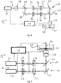
- Fig. 2 schematically shows an apparatus 15 for optically fabricating a structured object.
- the apparatus 15 comprises a light source section 16 comprising means 19 for generating a first light beam 20 and means 21 for generating a second light beam 22.
- the apparatus 15 further comprises a container 24, in which a liquid photo-curing material 25 is retained.
- the first light beam 20 provides a photon energy that matches the energy gap of the photo-curing material for absorption, thereby causing a curing process, particularly a polymerization, in the photo-curing material 25 by linear absorption of light.
- the second light beam 22 provides a photon energy less than the energy gap of the photo-curing material 25 for absorption, causing a curing process in the photo-curing material by non-linear multiple photon absorption.
- the photon energy of the second light beam 22 is half of the energy gap for absorption to cause two-photon absorption for curing the photo-curing material 25.
- the apparatus 15 comprises means 29 for directing the first light beam 20 to first focus positions within the photo-curing material 25 and means 31 for directing the second light beam 22 to second focus positions within the photo-curing material 25.
- the means 29 for directing the first light beam 20 to first focus positions comprises a first intensity modulator 32, a first mirror 34 and a first spatial light modulator 36.
- the means 31 for directing the second light beam 22 to second focus positions comprises a second intensity modulator 33, a second spatial light modulator 37 and a second mirror 35.
- the first mirror 34 is a dichroic mirror, which reflects the first light beam 20 and passes the second light beam 22.
- an acousto-optic modulator is used as the first intensity modulator 32 and another acousto-optic modulator is used as the second intensity modulator 33.
- the acousto-optic modulator is used to control the intensity of the passing light beams 20, 22, which particularly represents the first-order beam of the acousto-optic modulator.
- a modulator element is used, which spatially modulates the intensity and/or the phase of the passing first and second light beam 20, 22, respectively. This allows modulating the spatial intensity distribution of the first light beam 20 and of the second light beam 22. It further allows moving the focus positions within the photo-curing material 25 without the need of a mechanical movement of components.
- the first light beam 20 and the second light beam 22 are subsequently focused by a common focusing optics 39 to multiple focus positions within the photo-curing material 25.
- the focusing optics 39 is movable along the z-direction.
- the container 24 is movable along the x-y-plane.
- a controller 40 is further comprised to control the means 19 for generating a first light beam 20, the means 21 for generating a second light beam 22, the first and second intensity modulators 32, 33, the first and second spatial light modulators 36, 37 and the movement of the common focusing optics 39 and of the container 24.
- the controller 40 is adapted to control the apparatus 15 according to the fabrication process shown in fig. 1 .
- Fig. 3 depicts another embodiment of an optical fabricating apparatus 15'.
- a first beam splitter 41 is placed in the path of the first light beam 20 and a second beam splitter 42 is placed in the path of the second light beam 22.
- the first beam splitter 41 is a dichroic optical element, which passes light of the second light beam 22.
- a first light beam 20 and a second light beam 22 are directed in parallel to the photo-curing material 25 contained in the container 24.
- a separate common focusing optics 39, 44 is used to focus the first light beam 20 and the second light beam 22 in parallel to different first focus positions and to different second focus positions. This allows fabricating two structured objects or different structures of the same object in parallel.
- the common focusing optics 39, 44 are both movable along the x-, y- and z-direction.
- a third embodiment of the optical fabricating apparatus 15" is shown in fig. 4 .
- the light source section 16 of the apparatus 15" shown in fig. 4 comprises means 21 for generating a second light beam 22.
- a second harmonic generator 46 the first light beam 20 is generated by the second light beam 22 by a second harmonic generation.
- a beam splitter 47 the first light beam 20 is separated from the second light beam 22.
- a mirror 48 is placed into the path of the first light beam 20 for reflection.
- the other components of the apparatus 15" shown in fig. 4 are similar to those of the apparatus 15 shown in fig. 2 .
- FIG. 5 A fourth embodiment of an optical fabricating apparatus 15'" is depicted in fig. 5 .
- the container 24 is placed above the common focusing optics 39.
- the object to be fabricated is formed in layers on the bottom side of a movable platform 49.
- the platform 49 is movable along the z-direction.
- the common focusing optics 39 is movable along the x-y-plane.
- the other components of the apparatus 15'" according to fig. 5 are identical to those of the apparatus 15 shown in fig. 2 .
Landscapes
- Engineering & Computer Science (AREA)
- Physics & Mathematics (AREA)
- Chemical & Material Sciences (AREA)
- Materials Engineering (AREA)
- Optics & Photonics (AREA)
- Manufacturing & Machinery (AREA)
- Health & Medical Sciences (AREA)
- Toxicology (AREA)
- Mechanical Engineering (AREA)
- General Physics & Mathematics (AREA)
- Microelectronics & Electronic Packaging (AREA)
- Plasma & Fusion (AREA)
Claims (15)
- Procédé pour fabriquer un objet structuré, dans lequel un matériau photodurcissable (25), qui est durci par exposition à de la lumière et qui est placé à l'intérieur de couches successives, est exposé à de la lumière fournissant de l'énergie qui est transformée par absorption en énergie interne du matériau photodurcissable (25) pour le durcissement, formant ainsi l'objet, le procédé comprenant les étapes consistant :- à identifier dans chaque couche individuelle de la succession de couches des structures grossières de l'objet et des structures fines de l'objet,- à diriger un premier faisceau lumineux (20) vers des premières positions de focalisation à l'intérieur du matériau photodurcissable (25), lequel premier faisceau lumineux fournit une énergie monophotonique correspondant à la largeur de bande interdite du matériau photodurcissable (25) pour l'absorption, les premières positions de focalisation étant associées aux structures grossières de l'objet à l'intérieure d'une première couche individuelle de la succession de couches, en vue de durcir le matériau photodurcissable (25) dans les premières positions de focalisation formant ainsi les structures grossières de l'objet à l'intérieur de ladite première couche individuelle,- à diriger simultanément ou ultérieurement un second faisceau lumineux (22) vers des secondes positions de focalisation à l'intérieur du matériau photodurcissable (25), lequel second faisceau lumineux fournit une énergie monophotonique inférieure à la largeur de bande interdite du matériau photodurcissable (25) pour l'absorption, les secondes positions de focalisation étant associées aux structures fines de l'objet à l'intérieur de ladite première couche individuelle, en vue de durcir le matériau photodurcissable (25) dans les secondes positions de focalisation par absorption multiphotonique, formant ainsi les structures fines de l'objet à l'intérieur de ladite première couche individuelle, et- à répéter les étapes consistant à diriger le premier faisceau lumineux (20) vers des premières positions de focalisation et le second faisceau lumineux (22) vers des secondes positions de focalisation à l'intérieur d'une une couche suivante et de toutes les couches individuelles restantes de la succession de couches.
- Procédé selon la revendication 1, dans lequel au moins l'un parmi le premier faisceau lumineux (20) et le second faisceau lumineux (22) est divisé en une pluralité de faisceaux lumineux dirigés vers des positions de focalisation à l'intérieur du matériau photodurcissable (25), formant ainsi des structures multiples de l'objet et/ou plusieurs objets parallèlement.
- Procédé selon l'une quelconque des revendications précédentes, dans lequel l'intensité d'au moins l'un parmi le premier faisceau lumineux (20) et le second faisceau lumineux (22) est contrôlée durant la fabrication de l'objet, et/ou dans lequel au moins l'une parmi la phase, la polarisation et l'intensité d'au moins l'un parmi le premier faisceau lumineux (20) et le second faisceau lumineux (22) est modulée spatialement durant la fabrication de l'objet.
- Procédé selon l'une quelconque des revendications précédentes, dans lequel le premier faisceau de lumière (20) et le second faisceau de lumière (22) sont focalisés à l'aide d'une optique de focalisation de lumière ordinaire (39).
- Procédé selon l'une quelconque des revendications précédentes, dans lequel le premier faisceau lumineux (20) est généré par le second faisceau lumineux (22) par un processus de génération de seconde harmonique.
- Procédé selon l'une quelconque des revendications 1 à 4, dans lequel le premier faisceau lumineux (20) est généré par un laser à diode, le laser à diode émettant en particulier une lumière ultraviolette.
- Procédé selon l'une quelconque des revendications précédentes, dans lequel le second faisceau lumineux (22) est généré par un laser pulsé, le laser pulsé émettant en particulier des impulsions laser infrarouges.
- Procédé selon l'une quelconque des revendications précédentes, dans lequel les couches individuelles de la succession de couches ont chacune une épaisseur comprise entre 10 µm et 100 µm, et/ou dans lequel les structures grossières comprennent des éléments structuraux ayant une taille comprise entre 10 µm et 100 µm, et/ou dans lequel les structures fines comprennent des éléments structuraux ayant une taille comprise entre 100 nm et 500 nm.
- Appareil (15, 15', 15", 15"'), dans lequel un matériau de photodurcissable (25), qui est durci par exposition à de la lumière et qui est placé à l'intérieur de couches successives, est exposé à de la lumière fournissant de l'énergie qui est transformée par absorption en énergie interne du matériau photodurcissable (25) pour le durcissement, formant ainsi l'objet, l'appareil (15) comprenant :- une section de source de lumière (16) comprenant des moyens (19, 21) pour générer un premier faisceau lumineux (20), lequel fournit une énergie monophotonique correspondant à la largeur de bande interdite du matériau de photodurcissable (25) pour l'absorption, et pour générer un second faisceau lumineux (22), lequel fournit une énergie monophotonique inférieure à la largeur de bande interdite du matériau photodurcissable (25) pour l'absorption, afin de provoquer un phénomène d'absorption multiphotonique dans le matériau de photodurcissable (25),- un récipient (24) apte à contenir le matériau de photodurcissable (25),- des moyens (29) pour diriger le premier faisceau lumineux (20) vers des premières positions de focalisation à l'intérieur du matériau de photodurcissable (25),- des moyens (31) pour diriger le second faisceau lumineux (22) vers des secondes positions de focalisation à l'intérieur du matériau de photodurcissable (25), et- un contrôleur (40) apteà identifier à l'intérieur de chaque couche individuelle de la succession de couches des structures grossières de l'objet et des structures fines de l'objet,
à commander les moyens (29) pour diriger le premier faisceau lumineux (20) vers des premières positions de focalisation associées aux structures grossières de l'objet à l'intérieure d'une première couche individuelle de la succession de couches pour durcir le matériau photodurcissable (25) aux premières positions de focalisation, formant ainsi les structures grossières de l'objet à l'intérieur de ladite première couche individuelle,
à commander les moyens (31) pour diriger le second faisceau lumineux (22) vers des secondes positions de focalisation associées aux structures fines de l'objet à l'intérieur de ladite première couche individuelle pour durcir le matériau photodurcissable (25) aux secondes positions de focalisation par absorption multiphotonique, formant ainsi les structures fines de l'objet à l'intérieur de ladite première couche individuelle, et
à répéter les étapes consistant à diriger le premier faisceau lumineux (20) vers des premières positions de focalisation et le second faisceau de lumière (22) vers des secondes positions de focalisation à l'intérieur d'une couche suivante et de toutes les couches individuelles restantes de la succession de couches. - Appareil (15, 15', 15", 15"') selon la revendication 9, dans lequel au moins l'un parmi les moyens (29) pour diriger le premier faisceau lumineux (20) vers des premières positions de focalisation et les moyens (31) pour diriger le second faisceau lumineux (22) vers des secondes positions de focalisation comprend au moins un élément diviseur de faisceau (41, 42) pour diviser respectivement le premier et/ou le second faisceau lumineux (20, 22) en une pluralité de faisceaux lumineux, et le contrôleur (40) étant en outre apte à commander les moyens (29) pour diriger le premier faisceau lumineux (20) et/ou les moyens (31) pour diriger le second faisceau lumineux (22) en vue de former des structures multiples de l'objet et/ou plusieurs objets parallèlement.
- Appareil (15, 15', 15", 15"') selon la revendication 9 ou 10, dans lequel au moins l'un parmi les moyens (29) pour diriger le premier faisceau lumineux (20) vers des premières positions de focalisation et les moyens (31) pour diriger le second faisceau lumineux (22) vers des secondes positions de focalisation comprend au moins un modulateur d'intensité pouvant être commandé (32, 33), et le contrôleur (40) étant en outre apte à commander à l'aide du au moins un modulateur d'intensité (32, 33) l'intensité respectivement du premier faisceau lumineux (20) et/ou du second faisceau lumineux (22) durant la fabrication de l'objet.
- Appareil (15, 15', 15", 15"') selon l'une quelconque des revendications 9 à 11, dans lequel au moins l'un parmi les moyens (29) pour diriger le premier faisceau lumineux (20) vers des premières positions de focalisation et les moyens (31) pour diriger le second faisceau lumineux (22) vers des secondes positions de focalisation comprend un modulateur spatial de lumière pouvant être commandé (36, 37), et le contrôleur (40) étant en outre apte à commander au moins l'une parmi la phase, la polarisation et l'intensité respectivement du premier faisceau lumineux (20) et/ou du second faisceau lumineux (22) à l'aide d'au moins un modulateur spatial (36, 37).
- Appareil (15, 15', 15", 15"') selon l'une quelconque des revendications 9 à 12, dans lequel les moyens (29) pour diriger le premier faisceau lumineux (20) vers des premières positions de focalisation et les moyens (31) pour diriger le second faisceau lumineux (22) vers des secondes positions de focalisation comprennent une optique de focalisation de lumière ordinaire (39).
- Appareil (15, 15', 15", 15"') selon l'une quelconque des revendications 9 à 13, dans lequel la section de source de lumière (16) comprend un laser à diode apte à générer le premier faisceau lumineux, en particulier de lumière ultraviolette, ou dans lequel la section de source de lumière (16) comprend un laser pulsé apte à générer des impulsions du second faisceau lumineux, en particulier de la lumière infrarouge.
- Appareil (15, 15', 15", 15"') selon l'une quelconque des revendications 9 à 14, dans lequel la section de source de lumière (16) comprend un générateur de seconde harmonique (46) apte à générer le premier faisceau lumineux (20) par le second faisceau lumineux (22) par un processus de génération de seconde harmonique.
Priority Applications (3)
| Application Number | Priority Date | Filing Date | Title |
|---|---|---|---|
| EP16156116.2A EP3208075B1 (fr) | 2016-02-17 | 2016-02-17 | Procédé optique et appareil de fabrication d'un objet structuré |
| PCT/EP2017/052705 WO2017140546A1 (fr) | 2016-02-17 | 2017-02-08 | Procédé optique et appareil pour la fabrication d'un objet structuré |
| US16/104,603 US10442133B2 (en) | 2016-02-17 | 2018-08-17 | Optical method and apparatus for fabricating a structured object |
Applications Claiming Priority (1)
| Application Number | Priority Date | Filing Date | Title |
|---|---|---|---|
| EP16156116.2A EP3208075B1 (fr) | 2016-02-17 | 2016-02-17 | Procédé optique et appareil de fabrication d'un objet structuré |
Publications (2)
| Publication Number | Publication Date |
|---|---|
| EP3208075A1 EP3208075A1 (fr) | 2017-08-23 |
| EP3208075B1 true EP3208075B1 (fr) | 2018-06-13 |
Family
ID=55628715
Family Applications (1)
| Application Number | Title | Priority Date | Filing Date |
|---|---|---|---|
| EP16156116.2A Active EP3208075B1 (fr) | 2016-02-17 | 2016-02-17 | Procédé optique et appareil de fabrication d'un objet structuré |
Country Status (3)
| Country | Link |
|---|---|
| US (1) | US10442133B2 (fr) |
| EP (1) | EP3208075B1 (fr) |
| WO (1) | WO2017140546A1 (fr) |
Families Citing this family (11)
| Publication number | Priority date | Publication date | Assignee | Title |
|---|---|---|---|---|
| US11104075B2 (en) | 2018-11-01 | 2021-08-31 | Stratasys, Inc. | System for window separation in an additive manufacturing process |
| US10723069B2 (en) | 2018-11-01 | 2020-07-28 | Origin Laboratories, Inc. | Method for build separation from a curing interface in an additive manufacturing process |
| DE102018009916A1 (de) | 2018-12-17 | 2020-07-02 | Karlsruher Institut für Technologie | Parallelisierte 3D-Lithographie mittels mehrstraliger, mehrfarbiger lichtinduzierter Polymerisation |
| EP3934914A4 (fr) * | 2019-03-08 | 2022-11-02 | University of Pittsburgh - of the Commonwealth System of Higher Education | Systèmes et procédés de fabrication additive basée sur la photopolymérisation activée par irradiations à de multiples longueurs d'onde |
| CN112339265A (zh) * | 2019-08-08 | 2021-02-09 | 安世亚太科技股份有限公司 | 一种用于光敏树脂的3d打印机系统及利用其的3d打印方法 |
| JP2022550054A (ja) * | 2019-09-27 | 2022-11-30 | プレリス バイオロジクス,インク. | 三次元印刷された臓器、デバイス、およびマトリックス |
| CN110605849B (zh) * | 2019-10-23 | 2021-12-21 | 东华大学 | 一种光固化三维打印预览方法 |
| DE102020200214A1 (de) * | 2020-01-09 | 2021-07-15 | Hochschule für angewandte Wissenschaften Kempten Körperschaft des öffentlichen Rechts | Konfokale Messvorrichtung zur 3D-Vermessung einer Objektoberfläche |
| DE102021101164B4 (de) | 2021-01-20 | 2024-06-27 | Xolo Gmbh | Verfahren und Vorrichtung zum Herstellen eines dreidimensionalen Objekts in einem optisch reaktiven Ausgangsmaterial |
| CN113276408A (zh) * | 2021-06-18 | 2021-08-20 | 四川大学 | 一种液体内连续光固化成型增材制造装置及其制造方法 |
| KR102497174B1 (ko) * | 2021-07-20 | 2023-02-09 | 한국생산기술연구원 | 이광자 스테레오리소그래피의 이중패터닝 방법 및 장치 |
Family Cites Families (12)
| Publication number | Priority date | Publication date | Assignee | Title |
|---|---|---|---|---|
| US5182056A (en) * | 1988-04-18 | 1993-01-26 | 3D Systems, Inc. | Stereolithography method and apparatus employing various penetration depths |
| US5460758A (en) * | 1990-12-21 | 1995-10-24 | Eos Gmbh Electro Optical Systems | Method and apparatus for production of a three-dimensional object |
| DE4302418A1 (de) * | 1993-01-28 | 1994-08-11 | Eos Electro Optical Syst | Verfahren und Vorrichtung zum Herstellen eines dreidimensionalen Objekts |
| US6122564A (en) * | 1998-06-30 | 2000-09-19 | Koch; Justin | Apparatus and methods for monitoring and controlling multi-layer laser cladding |
| US6406658B1 (en) | 1999-02-08 | 2002-06-18 | 3D Systems, Inc. | Stereolithographic method and apparatus for production of three dimensional objects using multiple beams of different diameters |
| US6624915B1 (en) | 2000-03-16 | 2003-09-23 | Science Applications International Corporation | Holographic recording and micro/nanofabrication via ultrafast holographic two-photon induced photopolymerization (H-TPIP) |
| DE10111422A1 (de) | 2001-03-09 | 2002-09-26 | Hannover Laser Zentrum | Verfahren und Vorrichtung zur Herstellung eines Formkörpers aus einem durch Bestrahlung zu verfestigenden flüssigen Material |
| US6841340B2 (en) | 2001-07-13 | 2005-01-11 | Fuji Photo Film Co., Ltd. | Optical fabricating method and apparatus |
| IT1395683B1 (it) | 2009-08-03 | 2012-10-16 | Dws Srl | Macchina stereolitografica perfezionata |
| DE102010020158A1 (de) * | 2010-05-11 | 2011-11-17 | Fraunhofer-Gesellschaft zur Förderung der angewandten Forschung e.V. | Vorrichtung sowie Verfahren zur Erzeugung dreidimensionaler Strukturen |
| JP5739010B2 (ja) | 2010-11-29 | 2015-06-24 | スリーディー システムズ インコーポレーテッド | 内部レーザ変調を使用したステレオリソグラフィー・システムおよび方法 |
| EP3094469B1 (fr) * | 2014-01-16 | 2019-11-13 | Hewlett-Packard Development Company, L.P. | Génération d'un objet tridimensionnel |
-
2016
- 2016-02-17 EP EP16156116.2A patent/EP3208075B1/fr active Active
-
2017
- 2017-02-08 WO PCT/EP2017/052705 patent/WO2017140546A1/fr not_active Ceased
-
2018
- 2018-08-17 US US16/104,603 patent/US10442133B2/en active Active
Non-Patent Citations (1)
| Title |
|---|
| None * |
Also Published As
| Publication number | Publication date |
|---|---|
| EP3208075A1 (fr) | 2017-08-23 |
| WO2017140546A1 (fr) | 2017-08-24 |
| US10442133B2 (en) | 2019-10-15 |
| US20190047224A1 (en) | 2019-02-14 |
Similar Documents
| Publication | Publication Date | Title |
|---|---|---|
| EP3208075B1 (fr) | Procédé optique et appareil de fabrication d'un objet structuré | |
| Wang et al. | Toward near-perfect diffractive optical elements via nanoscale 3D printing | |
| US10500796B1 (en) | Dynamic tissue microfabrication through digital photolithography system and methods | |
| EP3704545B1 (fr) | Système et procédé de polymérisation biphotonique parallèle à résolution en profondeur destinés à la fabrication additive submicronique extensible | |
| EP2569140B1 (fr) | Dispositif et procédé de production de structures tridimensionnelles | |
| Kondo et al. | Femtosecond laser interference technique with diffractive beam splitter for fabrication of three-dimensional photonic crystals | |
| DE102016214606B3 (de) | Verfahren und Vorrichtung zur lithographischen Erzeugung einer Zielstruktur an einer nicht-planaren Ausgangsstruktur | |
| JP4957242B2 (ja) | 光造形装置 | |
| WO2018036930A1 (fr) | Dispositif et procédé d'usinage laser de corps et/ou de surfaces | |
| Boniface et al. | Volumetric helical additive manufacturing | |
| CN101563212A (zh) | 聚合物对象光学制造工艺 | |
| JP2008545998A (ja) | ラピッドプロトタイピング装置およびラピッドプロトタイピングの方法 | |
| US20240051233A1 (en) | Method for printing a 3d object in a photoreactive composition, and printer suitable for implementing the method | |
| US20160332365A1 (en) | Process for producing a three-dimensional structure | |
| JP2020524623A (ja) | 光造形物の製造方法および光造形装置 | |
| DE102014010412B4 (de) | Verfahren und Anordnung zur generativen Fertigung von Bauteilen | |
| Unlu et al. | Single-photon-assisted two-photon polymerization | |
| CN112297422B (zh) | 一种一次成型的3d打印装置 | |
| JP2009166448A (ja) | 光造形装置および光造形方法 | |
| KR102497174B1 (ko) | 이광자 스테레오리소그래피의 이중패터닝 방법 및 장치 | |
| Gandhi et al. | 3D microfabrication using bulk lithography | |
| Hinze et al. | Light sources and systems for multiphoton lithography | |
| WO2024161177A1 (fr) | Procédé et système d'allongement de voxel en fabrication multiphotonique | |
| DE102005003218B4 (de) | Vorrichtung und Verfahren zum Herstellen eines dreidimensionalen Gegenstandes mittels Stereolithographie | |
| Jiang | Development of a novel two‐laser beam stereolithography system |
Legal Events
| Date | Code | Title | Description |
|---|---|---|---|
| PUAI | Public reference made under article 153(3) epc to a published international application that has entered the european phase |
Free format text: ORIGINAL CODE: 0009012 |
|
| STAA | Information on the status of an ep patent application or granted ep patent |
Free format text: STATUS: REQUEST FOR EXAMINATION WAS MADE |
|
| 17P | Request for examination filed |
Effective date: 20161222 |
|
| AK | Designated contracting states |
Kind code of ref document: A1 Designated state(s): AL AT BE BG CH CY CZ DE DK EE ES FI FR GB GR HR HU IE IS IT LI LT LU LV MC MK MT NL NO PL PT RO RS SE SI SK SM TR |
|
| AX | Request for extension of the european patent |
Extension state: BA ME |
|
| REG | Reference to a national code |
Ref country code: DE Ref legal event code: R079 Ref document number: 602016003423 Country of ref document: DE Free format text: PREVIOUS MAIN CLASS: B29C0067000000 Ipc: B29C0064135000 |
|
| RIC1 | Information provided on ipc code assigned before grant |
Ipc: B29C 64/277 20170101ALI20171116BHEP Ipc: B29C 64/135 20170101AFI20171116BHEP Ipc: B33Y 10/00 20150101ALN20171116BHEP Ipc: B33Y 30/00 20150101ALN20171116BHEP |
|
| GRAP | Despatch of communication of intention to grant a patent |
Free format text: ORIGINAL CODE: EPIDOSNIGR1 |
|
| STAA | Information on the status of an ep patent application or granted ep patent |
Free format text: STATUS: GRANT OF PATENT IS INTENDED |
|
| INTG | Intention to grant announced |
Effective date: 20180109 |
|
| RIN1 | Information on inventor provided before grant (corrected) |
Inventor name: TRAUTMANN, ANIKA Inventor name: HELLMANN, RALF |
|
| GRAS | Grant fee paid |
Free format text: ORIGINAL CODE: EPIDOSNIGR3 |
|
| GRAA | (expected) grant |
Free format text: ORIGINAL CODE: 0009210 |
|
| STAA | Information on the status of an ep patent application or granted ep patent |
Free format text: STATUS: THE PATENT HAS BEEN GRANTED |
|
| AK | Designated contracting states |
Kind code of ref document: B1 Designated state(s): AL AT BE BG CH CY CZ DE DK EE ES FI FR GB GR HR HU IE IS IT LI LT LU LV MC MK MT NL NO PL PT RO RS SE SI SK SM TR |
|
| REG | Reference to a national code |
Ref country code: GB Ref legal event code: FG4D |
|
| REG | Reference to a national code |
Ref country code: CH Ref legal event code: EP Ref country code: AT Ref legal event code: REF Ref document number: 1008017 Country of ref document: AT Kind code of ref document: T Effective date: 20180615 |
|
| REG | Reference to a national code |
Ref country code: IE Ref legal event code: FG4D |
|
| REG | Reference to a national code |
Ref country code: DE Ref legal event code: R096 Ref document number: 602016003423 Country of ref document: DE |
|
| REG | Reference to a national code |
Ref country code: CH Ref legal event code: NV Representative=s name: E. BLUM AND CO. AG PATENT- UND MARKENANWAELTE , CH |
|
| REG | Reference to a national code |
Ref country code: NL Ref legal event code: MP Effective date: 20180613 |
|
| REG | Reference to a national code |
Ref country code: LT Ref legal event code: MG4D |
|
| PG25 | Lapsed in a contracting state [announced via postgrant information from national office to epo] |
Ref country code: SE Free format text: LAPSE BECAUSE OF FAILURE TO SUBMIT A TRANSLATION OF THE DESCRIPTION OR TO PAY THE FEE WITHIN THE PRESCRIBED TIME-LIMIT Effective date: 20180613 Ref country code: FI Free format text: LAPSE BECAUSE OF FAILURE TO SUBMIT A TRANSLATION OF THE DESCRIPTION OR TO PAY THE FEE WITHIN THE PRESCRIBED TIME-LIMIT Effective date: 20180613 Ref country code: BG Free format text: LAPSE BECAUSE OF FAILURE TO SUBMIT A TRANSLATION OF THE DESCRIPTION OR TO PAY THE FEE WITHIN THE PRESCRIBED TIME-LIMIT Effective date: 20180913 Ref country code: NO Free format text: LAPSE BECAUSE OF FAILURE TO SUBMIT A TRANSLATION OF THE DESCRIPTION OR TO PAY THE FEE WITHIN THE PRESCRIBED TIME-LIMIT Effective date: 20180913 Ref country code: CY Free format text: LAPSE BECAUSE OF FAILURE TO SUBMIT A TRANSLATION OF THE DESCRIPTION OR TO PAY THE FEE WITHIN THE PRESCRIBED TIME-LIMIT Effective date: 20180613 Ref country code: LT Free format text: LAPSE BECAUSE OF FAILURE TO SUBMIT A TRANSLATION OF THE DESCRIPTION OR TO PAY THE FEE WITHIN THE PRESCRIBED TIME-LIMIT Effective date: 20180613 |
|
| PG25 | Lapsed in a contracting state [announced via postgrant information from national office to epo] |
Ref country code: GR Free format text: LAPSE BECAUSE OF FAILURE TO SUBMIT A TRANSLATION OF THE DESCRIPTION OR TO PAY THE FEE WITHIN THE PRESCRIBED TIME-LIMIT Effective date: 20180914 Ref country code: HR Free format text: LAPSE BECAUSE OF FAILURE TO SUBMIT A TRANSLATION OF THE DESCRIPTION OR TO PAY THE FEE WITHIN THE PRESCRIBED TIME-LIMIT Effective date: 20180613 Ref country code: LV Free format text: LAPSE BECAUSE OF FAILURE TO SUBMIT A TRANSLATION OF THE DESCRIPTION OR TO PAY THE FEE WITHIN THE PRESCRIBED TIME-LIMIT Effective date: 20180613 Ref country code: RS Free format text: LAPSE BECAUSE OF FAILURE TO SUBMIT A TRANSLATION OF THE DESCRIPTION OR TO PAY THE FEE WITHIN THE PRESCRIBED TIME-LIMIT Effective date: 20180613 |
|
| REG | Reference to a national code |
Ref country code: AT Ref legal event code: MK05 Ref document number: 1008017 Country of ref document: AT Kind code of ref document: T Effective date: 20180613 |
|
| PG25 | Lapsed in a contracting state [announced via postgrant information from national office to epo] |
Ref country code: NL Free format text: LAPSE BECAUSE OF FAILURE TO SUBMIT A TRANSLATION OF THE DESCRIPTION OR TO PAY THE FEE WITHIN THE PRESCRIBED TIME-LIMIT Effective date: 20180613 |
|
| PG25 | Lapsed in a contracting state [announced via postgrant information from national office to epo] |
Ref country code: RO Free format text: LAPSE BECAUSE OF FAILURE TO SUBMIT A TRANSLATION OF THE DESCRIPTION OR TO PAY THE FEE WITHIN THE PRESCRIBED TIME-LIMIT Effective date: 20180613 Ref country code: CZ Free format text: LAPSE BECAUSE OF FAILURE TO SUBMIT A TRANSLATION OF THE DESCRIPTION OR TO PAY THE FEE WITHIN THE PRESCRIBED TIME-LIMIT Effective date: 20180613 Ref country code: EE Free format text: LAPSE BECAUSE OF FAILURE TO SUBMIT A TRANSLATION OF THE DESCRIPTION OR TO PAY THE FEE WITHIN THE PRESCRIBED TIME-LIMIT Effective date: 20180613 Ref country code: AT Free format text: LAPSE BECAUSE OF FAILURE TO SUBMIT A TRANSLATION OF THE DESCRIPTION OR TO PAY THE FEE WITHIN THE PRESCRIBED TIME-LIMIT Effective date: 20180613 Ref country code: IS Free format text: LAPSE BECAUSE OF FAILURE TO SUBMIT A TRANSLATION OF THE DESCRIPTION OR TO PAY THE FEE WITHIN THE PRESCRIBED TIME-LIMIT Effective date: 20181013 Ref country code: PL Free format text: LAPSE BECAUSE OF FAILURE TO SUBMIT A TRANSLATION OF THE DESCRIPTION OR TO PAY THE FEE WITHIN THE PRESCRIBED TIME-LIMIT Effective date: 20180613 Ref country code: SK Free format text: LAPSE BECAUSE OF FAILURE TO SUBMIT A TRANSLATION OF THE DESCRIPTION OR TO PAY THE FEE WITHIN THE PRESCRIBED TIME-LIMIT Effective date: 20180613 |
|
| PG25 | Lapsed in a contracting state [announced via postgrant information from national office to epo] |
Ref country code: IT Free format text: LAPSE BECAUSE OF FAILURE TO SUBMIT A TRANSLATION OF THE DESCRIPTION OR TO PAY THE FEE WITHIN THE PRESCRIBED TIME-LIMIT Effective date: 20180613 Ref country code: SM Free format text: LAPSE BECAUSE OF FAILURE TO SUBMIT A TRANSLATION OF THE DESCRIPTION OR TO PAY THE FEE WITHIN THE PRESCRIBED TIME-LIMIT Effective date: 20180613 Ref country code: ES Free format text: LAPSE BECAUSE OF FAILURE TO SUBMIT A TRANSLATION OF THE DESCRIPTION OR TO PAY THE FEE WITHIN THE PRESCRIBED TIME-LIMIT Effective date: 20180613 |
|
| REG | Reference to a national code |
Ref country code: DE Ref legal event code: R097 Ref document number: 602016003423 Country of ref document: DE |
|
| PLBE | No opposition filed within time limit |
Free format text: ORIGINAL CODE: 0009261 |
|
| STAA | Information on the status of an ep patent application or granted ep patent |
Free format text: STATUS: NO OPPOSITION FILED WITHIN TIME LIMIT |
|
| 26N | No opposition filed |
Effective date: 20190314 |
|
| PG25 | Lapsed in a contracting state [announced via postgrant information from national office to epo] |
Ref country code: DK Free format text: LAPSE BECAUSE OF FAILURE TO SUBMIT A TRANSLATION OF THE DESCRIPTION OR TO PAY THE FEE WITHIN THE PRESCRIBED TIME-LIMIT Effective date: 20180613 |
|
| PG25 | Lapsed in a contracting state [announced via postgrant information from national office to epo] |
Ref country code: LU Free format text: LAPSE BECAUSE OF NON-PAYMENT OF DUE FEES Effective date: 20190217 Ref country code: MC Free format text: LAPSE BECAUSE OF FAILURE TO SUBMIT A TRANSLATION OF THE DESCRIPTION OR TO PAY THE FEE WITHIN THE PRESCRIBED TIME-LIMIT Effective date: 20180613 |
|
| REG | Reference to a national code |
Ref country code: BE Ref legal event code: MM Effective date: 20190228 |
|
| REG | Reference to a national code |
Ref country code: IE Ref legal event code: MM4A |
|
| PG25 | Lapsed in a contracting state [announced via postgrant information from national office to epo] |
Ref country code: AL Free format text: LAPSE BECAUSE OF FAILURE TO SUBMIT A TRANSLATION OF THE DESCRIPTION OR TO PAY THE FEE WITHIN THE PRESCRIBED TIME-LIMIT Effective date: 20180613 |
|
| PG25 | Lapsed in a contracting state [announced via postgrant information from national office to epo] |
Ref country code: IE Free format text: LAPSE BECAUSE OF NON-PAYMENT OF DUE FEES Effective date: 20190217 |
|
| PG25 | Lapsed in a contracting state [announced via postgrant information from national office to epo] |
Ref country code: BE Free format text: LAPSE BECAUSE OF NON-PAYMENT OF DUE FEES Effective date: 20190228 |
|
| PG25 | Lapsed in a contracting state [announced via postgrant information from national office to epo] |
Ref country code: TR Free format text: LAPSE BECAUSE OF FAILURE TO SUBMIT A TRANSLATION OF THE DESCRIPTION OR TO PAY THE FEE WITHIN THE PRESCRIBED TIME-LIMIT Effective date: 20180613 |
|
| PG25 | Lapsed in a contracting state [announced via postgrant information from national office to epo] |
Ref country code: PT Free format text: LAPSE BECAUSE OF FAILURE TO SUBMIT A TRANSLATION OF THE DESCRIPTION OR TO PAY THE FEE WITHIN THE PRESCRIBED TIME-LIMIT Effective date: 20181015 Ref country code: MT Free format text: LAPSE BECAUSE OF NON-PAYMENT OF DUE FEES Effective date: 20190217 |
|
| PG25 | Lapsed in a contracting state [announced via postgrant information from national office to epo] |
Ref country code: HU Free format text: LAPSE BECAUSE OF FAILURE TO SUBMIT A TRANSLATION OF THE DESCRIPTION OR TO PAY THE FEE WITHIN THE PRESCRIBED TIME-LIMIT; INVALID AB INITIO Effective date: 20160217 |
|
| PG25 | Lapsed in a contracting state [announced via postgrant information from national office to epo] |
Ref country code: SI Free format text: LAPSE BECAUSE OF FAILURE TO SUBMIT A TRANSLATION OF THE DESCRIPTION OR TO PAY THE FEE WITHIN THE PRESCRIBED TIME-LIMIT Effective date: 20180613 |
|
| PG25 | Lapsed in a contracting state [announced via postgrant information from national office to epo] |
Ref country code: MK Free format text: LAPSE BECAUSE OF FAILURE TO SUBMIT A TRANSLATION OF THE DESCRIPTION OR TO PAY THE FEE WITHIN THE PRESCRIBED TIME-LIMIT Effective date: 20180613 |
|
| PGFP | Annual fee paid to national office [announced via postgrant information from national office to epo] |
Ref country code: GB Payment date: 20221230 Year of fee payment: 8 |
|
| PGFP | Annual fee paid to national office [announced via postgrant information from national office to epo] |
Ref country code: FR Payment date: 20230110 Year of fee payment: 8 Ref country code: CH Payment date: 20230307 Year of fee payment: 8 |
|
| PGFP | Annual fee paid to national office [announced via postgrant information from national office to epo] |
Ref country code: DE Payment date: 20221230 Year of fee payment: 8 |
|
| REG | Reference to a national code |
Ref country code: DE Ref legal event code: R119 Ref document number: 602016003423 Country of ref document: DE |
|
| REG | Reference to a national code |
Ref country code: CH Ref legal event code: PL |
|
| PG25 | Lapsed in a contracting state [announced via postgrant information from national office to epo] |
Ref country code: CH Free format text: LAPSE BECAUSE OF NON-PAYMENT OF DUE FEES Effective date: 20240229 |
|
| GBPC | Gb: european patent ceased through non-payment of renewal fee |
Effective date: 20240217 |
|
| PG25 | Lapsed in a contracting state [announced via postgrant information from national office to epo] |
Ref country code: CH Free format text: LAPSE BECAUSE OF NON-PAYMENT OF DUE FEES Effective date: 20240229 |
|
| PG25 | Lapsed in a contracting state [announced via postgrant information from national office to epo] |
Ref country code: DE Free format text: LAPSE BECAUSE OF NON-PAYMENT OF DUE FEES Effective date: 20240903 |
|
| PG25 | Lapsed in a contracting state [announced via postgrant information from national office to epo] |
Ref country code: GB Free format text: LAPSE BECAUSE OF NON-PAYMENT OF DUE FEES Effective date: 20240217 |
|
| PG25 | Lapsed in a contracting state [announced via postgrant information from national office to epo] |
Ref country code: FR Free format text: LAPSE BECAUSE OF NON-PAYMENT OF DUE FEES Effective date: 20240229 |
|
| PG25 | Lapsed in a contracting state [announced via postgrant information from national office to epo] |
Ref country code: GB Free format text: LAPSE BECAUSE OF NON-PAYMENT OF DUE FEES Effective date: 20240217 Ref country code: FR Free format text: LAPSE BECAUSE OF NON-PAYMENT OF DUE FEES Effective date: 20240229 Ref country code: DE Free format text: LAPSE BECAUSE OF NON-PAYMENT OF DUE FEES Effective date: 20240903 |