EP3208091B1 - Flüssigkeitsausgabevorrichtung und verfahren zum wischen eines flüssigkeitsausgabekopfs - Google Patents
Flüssigkeitsausgabevorrichtung und verfahren zum wischen eines flüssigkeitsausgabekopfs Download PDFInfo
- Publication number
- EP3208091B1 EP3208091B1 EP17151387.2A EP17151387A EP3208091B1 EP 3208091 B1 EP3208091 B1 EP 3208091B1 EP 17151387 A EP17151387 A EP 17151387A EP 3208091 B1 EP3208091 B1 EP 3208091B1
- Authority
- EP
- European Patent Office
- Prior art keywords
- nozzle
- wiper
- nozzle plate
- ink
- wiping
- Prior art date
- Legal status (The legal status is an assumption and is not a legal conclusion. Google has not performed a legal analysis and makes no representation as to the accuracy of the status listed.)
- Active
Links
Images


Classifications
-
- B—PERFORMING OPERATIONS; TRANSPORTING
- B41—PRINTING; LINING MACHINES; TYPEWRITERS; STAMPS
- B41J—TYPEWRITERS; SELECTIVE PRINTING MECHANISMS, i.e. MECHANISMS PRINTING OTHERWISE THAN FROM A FORME; CORRECTION OF TYPOGRAPHICAL ERRORS
- B41J2/00—Typewriters or selective printing mechanisms characterised by the printing or marking process for which they are designed
- B41J2/005—Typewriters or selective printing mechanisms characterised by the printing or marking process for which they are designed characterised by bringing liquid or particles selectively into contact with a printing material
- B41J2/01—Ink jet
- B41J2/135—Nozzles
- B41J2/165—Prevention or detection of nozzle clogging, e.g. cleaning, capping or moistening for nozzles
- B41J2/16517—Cleaning of print head nozzles
- B41J2/16535—Cleaning of print head nozzles using wiping constructions
- B41J2/16541—Means to remove deposits from wipers or scrapers
-
- B—PERFORMING OPERATIONS; TRANSPORTING
- B41—PRINTING; LINING MACHINES; TYPEWRITERS; STAMPS
- B41J—TYPEWRITERS; SELECTIVE PRINTING MECHANISMS, i.e. MECHANISMS PRINTING OTHERWISE THAN FROM A FORME; CORRECTION OF TYPOGRAPHICAL ERRORS
- B41J2/00—Typewriters or selective printing mechanisms characterised by the printing or marking process for which they are designed
- B41J2/005—Typewriters or selective printing mechanisms characterised by the printing or marking process for which they are designed characterised by bringing liquid or particles selectively into contact with a printing material
- B41J2/01—Ink jet
- B41J2/135—Nozzles
- B41J2/165—Prevention or detection of nozzle clogging, e.g. cleaning, capping or moistening for nozzles
- B41J2/16517—Cleaning of print head nozzles
- B41J2/16535—Cleaning of print head nozzles using wiping constructions
- B41J2/16544—Constructions for the positioning of wipers
-
- B—PERFORMING OPERATIONS; TRANSPORTING
- B41—PRINTING; LINING MACHINES; TYPEWRITERS; STAMPS
- B41J—TYPEWRITERS; SELECTIVE PRINTING MECHANISMS, i.e. MECHANISMS PRINTING OTHERWISE THAN FROM A FORME; CORRECTION OF TYPOGRAPHICAL ERRORS
- B41J2/00—Typewriters or selective printing mechanisms characterised by the printing or marking process for which they are designed
- B41J2/005—Typewriters or selective printing mechanisms characterised by the printing or marking process for which they are designed characterised by bringing liquid or particles selectively into contact with a printing material
- B41J2/01—Ink jet
- B41J2/135—Nozzles
- B41J2/165—Prevention or detection of nozzle clogging, e.g. cleaning, capping or moistening for nozzles
- B41J2/16502—Printhead constructions to prevent nozzle clogging or facilitate nozzle cleaning
-
- B—PERFORMING OPERATIONS; TRANSPORTING
- B41—PRINTING; LINING MACHINES; TYPEWRITERS; STAMPS
- B41J—TYPEWRITERS; SELECTIVE PRINTING MECHANISMS, i.e. MECHANISMS PRINTING OTHERWISE THAN FROM A FORME; CORRECTION OF TYPOGRAPHICAL ERRORS
- B41J2/00—Typewriters or selective printing mechanisms characterised by the printing or marking process for which they are designed
- B41J2/005—Typewriters or selective printing mechanisms characterised by the printing or marking process for which they are designed characterised by bringing liquid or particles selectively into contact with a printing material
- B41J2/01—Ink jet
- B41J2/135—Nozzles
- B41J2/165—Prevention or detection of nozzle clogging, e.g. cleaning, capping or moistening for nozzles
- B41J2/16517—Cleaning of print head nozzles
- B41J2/16535—Cleaning of print head nozzles using wiping constructions
- B41J2/16538—Cleaning of print head nozzles using wiping constructions with brushes or wiper blades perpendicular to the nozzle plate
-
- B—PERFORMING OPERATIONS; TRANSPORTING
- B41—PRINTING; LINING MACHINES; TYPEWRITERS; STAMPS
- B41J—TYPEWRITERS; SELECTIVE PRINTING MECHANISMS, i.e. MECHANISMS PRINTING OTHERWISE THAN FROM A FORME; CORRECTION OF TYPOGRAPHICAL ERRORS
- B41J2/00—Typewriters or selective printing mechanisms characterised by the printing or marking process for which they are designed
- B41J2/005—Typewriters or selective printing mechanisms characterised by the printing or marking process for which they are designed characterised by bringing liquid or particles selectively into contact with a printing material
- B41J2/01—Ink jet
- B41J2/135—Nozzles
- B41J2/165—Prevention or detection of nozzle clogging, e.g. cleaning, capping or moistening for nozzles
- B41J2/16585—Prevention or detection of nozzle clogging, e.g. cleaning, capping or moistening for nozzles for paper-width or non-reciprocating print heads
-
- B—PERFORMING OPERATIONS; TRANSPORTING
- B41—PRINTING; LINING MACHINES; TYPEWRITERS; STAMPS
- B41J—TYPEWRITERS; SELECTIVE PRINTING MECHANISMS, i.e. MECHANISMS PRINTING OTHERWISE THAN FROM A FORME; CORRECTION OF TYPOGRAPHICAL ERRORS
- B41J2/00—Typewriters or selective printing mechanisms characterised by the printing or marking process for which they are designed
- B41J2/005—Typewriters or selective printing mechanisms characterised by the printing or marking process for which they are designed characterised by bringing liquid or particles selectively into contact with a printing material
- B41J2/01—Ink jet
- B41J2/135—Nozzles
- B41J2/165—Prevention or detection of nozzle clogging, e.g. cleaning, capping or moistening for nozzles
- B41J2/16517—Cleaning of print head nozzles
- B41J2/16535—Cleaning of print head nozzles using wiping constructions
Definitions
- the present invention relates to a liquid discharge apparatus and a method for wiping a liquid discharge head mounted in the liquid discharge apparatus.
- an ink jet type recording apparatus that discharges an ink as the liquid and performs printing on the recording medium such as paper or a recording sheet has been known.
- an ink jet type recording head mounted in such an ink jet type recording apparatus discharges an ink as ink droplets from a nozzle
- the ink is attached to the vicinity of the nozzle. Further, when viscosity of the attached ink is increased, there is a problem in that a discharge direction of ink droplets becomes unstable or a problem in that it is difficult to appropriately discharge ink droplets.
- nozzle surfaces of a plurality of nozzle heads arranged in a line head are wiped with a wiper.
- a side of the line head, on which the nozzle surfaces are arranged has a region in which the nozzle heads are arranged and a region in which no nozzle heads are arranged.
- the wiper is lifted and comes into contact with the line head, or is lowered and is separated from the line head.
- the wiper is lifted, comes into contact with the nozzle surface of the line head, and wipes the nozzle surface.
- the wiper recedes from the region in which the nozzle heads are arranged, the wiper is lowered and separated from the nozzle surface of the line head. Therefore, the wiper does not wipe the entire line head, but wipes the region in which the nozzle heads (nozzle surfaces) are arranged.
- the wiper is prevented from being abraded or chipped early and an occurrence of stain on the periphery of the line head through a wiping operation is prevented, compared to a case where the wiper wipes the entire line head.
- the ink discharged from the nozzle surface floats as mist and is attached to the region in which the nozzle heads are arranged or the region in which no nozzle heads are arranged.
- the ink attached to the region, in which the nozzles are arranged is removed, but the ink attached to the region, in which no nozzles are arranged, is not removed. Therefore, the ink (stain) remains in the region in which no nozzles are arranged.
- US 2014/253633 discloses a liquid discharging apparatus which includes a discharge head that includes a nozzle forming surface on which nozzles for discharging liquid are formed, a wiping member that performs wiping by relatively moving on the nozzle forming surface while abutting on the nozzle forming surface, and a cleaning liquid supply unit that supplies cleaning liquid provided for the wiping.
- the apparatus has a control unit that performs reciprocating wiping control which performs the wiping by causing the wiping member for holding the cleaning liquid supplied from the cleaning liquid supply unit to perform a reciprocating operation in which, after relative movement is performed in a first direction along the nozzle forming surface, relative movement is performed in a second direction which is opposite to the first direction.
- EP 1870241 discloses an image forming apparatus and a method of driving the image forming apparatus.
- the image forming apparatus includes an ink cartridge including a plurality of print heads arranged in a width direction of a paper sheet crossing a direction along which the print medium is transferred, a wiping unit moving in the transfer direction to wipe nozzle surfaces of the plurality of print heads, and a controller independently driving the plurality of print heads which have been wiped by the wiping unit, so that color nozzles of the plurality of print heads spray predetermined amounts of inks.
- US 2010/026757 discloses a liquid ejection head unit that has a carriage, a liquid ejection head for discharging liquid droplets through a nozzle opening of a nozzle formation surface, and a wiping member.
- the liquid ejection head and wiping member are moved relative to each other to allow the wiping member to come in contact and slide across the nozzle formation surface of the liquid ejection head so as to wipe the nozzle formation surface.
- An adhesion prevention plate is provided in the carriage on the downstream side in the wiping direction of the liquid ejection head.
- the liquids discharged from the nozzles float as mist and are attached to the wiping surface as stains. Further, foreign substances such as lint or dust are attached to the wiping surface and are mixed in the stains.
- a distance between an edge of the wiping surface and the nozzle is not uniform, and there are a portion having a long distance between the edge of the wiping surface and the nozzle and a portion having short distance between the edge of the wiping surface and the nozzle. Since the stains are attached substantially evenly to the wiping surface, a large number of the stains are attached in the portion having the long distance between the edge of the wiping surface and the nozzle and a small number of the stains are attached in the portion having the short distance between the edge of the wiping surface and the nozzle.
- the wiper When the wiper is caused to move from the portion having a small number of attachment of the stains toward the portion having a large number of attachment of the stains, the wiper is caused to move in a state in which the distance between the edge of the wiping surface and the nozzle on the upstream side in the moving direction of the wiper is shorter than the distance between the edge of the wiping surface and the nozzle on the downstream side in the moving direction of the wiper. Therefore, according to this application example, it is possible to reduce an occurrence of the problem arising in that foreign substances are rubbed into the inside of the nozzles and the ink discharge performance of the nozzles is degraded.
- the liquid contain a humectant
- the wiper wipe a nozzle that discharges a liquid having a low humectant content rate of the liquids, and then wipe a nozzle that discharges a liquid having a high humectant content rate of the liquids.
- the humectant has hygroscopicity, reduces evaporation of an aqueous solvent component in the liquid, and reduces a change in the properties of the liquid.
- the concentrations of the aqueous solvent component in the liquid having the low humectant content rate are different between the region in which the residue of the liquid occurs from the wiping and the region in which the residue of the liquid does not occur from the wiping, and it is difficult to evenly discharge the liquid having the low humectant content rate from the nozzles.
- the concentrations of the aqueous solvent components in the liquids having the high humectant content rate are the same in the region in which the residue of the liquid occurs from the wiping and the region in which the residue of the liquid does not occur from the wiping, it is possible to evenly discharge the liquid having the high humectant content rate from the nozzles, and it is possible to reduce an occurrence of a problem arising in that it is difficult to evenly discharge the liquids described above from the nozzles.
- the liquid having the low humectant content rate is positioned in the vicinity of the nozzle that discharges the liquid having the high humectant content rate, but the liquid having the high humectant content rate is not positioned in the vicinity of the nozzle that discharges the liquid having the low humectant content rate, due to the residue of the liquid. Therefore, it is possible to reduce an occurrence of a problem arising in that it is difficult to evenly discharge the liquids from the nozzles.
- the wiping surface have a plurality of nozzle plates in which the nozzles are formed, the nozzle plates be arranged in a zigzag pattern, and the nozzle plates be arranged at positions which are closer to the edge of the wiping surface on the upstream side than the edge on the downstream side, in the moving direction.
- the nozzle plates are arranged in a zigzag pattern on the wiping surface (arranged to be closer to one side), there are a portion having a long distance between the edge of the wiping surface and the nozzle plate and a portion having short distance between the edge of the wiping surface and the nozzle plate.
- the wiper is caused to move in a state in which the distance between the edge of the wiping surface and the nozzle plate on the upstream side in the moving direction of the wiper is shorter than the distance between the edge of the wiping surface and the nozzle plate on the downstream side in the moving direction of the wiper, the wiper is caused to move from the portion having a small number of attachment of the stains toward the portion having a large number of attachment of the stains.
- the wiping surface have a first nozzle plate and a second nozzle plate in which the nozzles are formed, and the wiper include a first wiper that wipes the first nozzle plate and a second wiper that wipes the second nozzle plate.
- the first wiper wipes the first nozzle plate and the second wiper wipes the second nozzle plate
- the wiping surface have a first nozzle plate and a second nozzle plate in which the nozzles are formed, and the wiper wipe the first nozzle plate, and then wipe the second nozzle plate.
- the wiper wipes the first nozzle plate, and then wipes the second nozzle plate, it is possible to perform appropriate wiping processes on the first nozzle plate and the second nozzle plate, respectively, compared to a case where the wiper simultaneously (collectively) wipes the first nozzle plate and the second nozzle plate.
- the wiping surface have a nozzle plate group including a first nozzle plate and a second nozzle plate in which the nozzles are formed and which are arranged in the moving direction, the nozzle plate group be disposed at a position which is closer to the edge of the wiping surface on the upstream side than the edge on the downstream side, in the moving direction, and the wiper wipe the nozzle plate group in the moving direction.
- the wiper can continually wipe the first nozzle plate and the second nozzle plate and it is efficient to perform the wiping process.
- the nozzle plate group is disposed to be closer to one side of the wiping surface, there are a portion having a long distance between the edge of the wiping surface and the nozzle plate group and a portion having short distance between the edge of the wiping surface and the nozzle plate group.
- the wiper is caused to move in a state in which the distance between the edge of the wiping surface and the nozzle plate group on the upstream side in the moving direction of the wiper is shorter than the distance between the edge of the wiping surface and the nozzle plate group on the downstream side in the moving direction of the wiper, the wiper is caused to move from the portion having a small number of attachment of the stains toward the portion having a large number of attachment of the stains.
- the wiping surface have a nozzle plate in which nozzles that discharge a liquid having a high viscosity of the liquids are formed and a nozzle plate in which nozzles that discharge a liquid having a low viscosity of the liquids are formed, and the wiper move with respect to the wiping surface at a slower speed on the nozzle plate in which the nozzles that discharge the liquid having the high viscosity of the liquids are formed than on the nozzle plate in which nozzles that discharge the liquid having the low viscosity of the liquids are formed.
- the liquid having the high viscosity is more difficult to flow than the liquid having the low viscosity, the liquid having the high viscosity that is attached to the wiping surface is more difficult to be removed through the wiping process than the liquid having the low viscosity that is attached to the wiping surface.
- the liquid having the high viscosity that is attached to the wiping surface be wiped with the wiping force applied for a longer time, than the liquid having the low viscosity that is attached to the wiping surface.
- the wiping force is applied, for a longer time, to the liquid (stains) having the high viscosity that is attached to the nozzle plate, and thus it is possible to appropriately remove the liquid (stains) having the high viscosity.
- the wiping surface include a first region in which the nozzles are arranged and a second region in which no nozzles are arranged, and the wiper move with respect to the wiping surface at a slower speed in the second region than in the first region.
- the stains attached to the first region, in which the nozzles are arranged, are removed by liquids discharged from the nozzles and the liquids discharged from the nozzles are attached to the first region. Further, since the liquids attached to the first region is changed to new liquids as the liquids are discharged from the nozzles, the liquids that is not subjected to a viscosity increase is attached to the first region.
- the stains attached to the second region are not removed by liquids discharged from the nozzles, then, liquids are discharged from the nozzles, and thereby stains are accumulated in the second region. Further, since the solvent component in the attached (accumulated) stains in the second region is evaporated, and the stains are increased in viscosity, the stains subjected to the viscosity increase are attached to the second region.
- the stains, which are attached to the second region and are subjected to the viscosity increase, are more difficult to flow than the liquids which are attached to the first region and are not subjected to the viscosity increase, it is preferable that the wiping force be applied for a long time, the removing performance of the stains of the wiping process be improved, and wiping be performed.
- the wiping force is applied to the stains that are attached to the second region and are subjected to the viscosity increase, for a long time, and thus it is possible to appropriately remove the stains which are attached to the second region and are subjected to the viscosity increase.
- a distance between an edge of the wiping surface and the nozzle is not uniform, and there are a portion having a long distance between the edge of the wiping surface and the nozzle and a portion having short distance between the edge of the wiping surface and the nozzle.
- the stains are attached substantially evenly to the wiping surface, a large number of the stains are attached in the portion having the long distance between the edge of the wiping surface and the nozzle and a small number of the stains are attached in the portion having the short distance between the edge of the wiping surface and the nozzle.
- the wiper when the wiper is caused to move from the portion having a small number of attachment of the stains toward the portion having a large number of attachment of the stains, a small amount of the stains (foreign substances) moves along with the wiper, the foreign substances are unlikely to be rubbed into the inside of the nozzles, and a problem of the degradation of the ink discharge performance of the nozzles is unlikely to arise, compared to a case where the wiper is caused to move from the portion having a large number of attachment of the stains toward the portion having a small number of attachment of the stains.
- the wiper When the wiper is caused to relatively move from the portion having a small number of attachment of the stains toward the portion having a large number of attachment of the stains and the wiper wipes the wiping surface, the wiper is caused to relatively move in a direction from the edge of the wiping surface on a side closer to the nozzle region toward the edge of the wiping surface on a side apart from the nozzle region, and the wiping is performed on the wiping surface. Therefore, according to the method for wiping a liquid discharge head of this application example, it is possible to reduce an occurrence of the problem arising in that foreign substances are rubbed into the inside of the nozzles and the ink discharge performance of the nozzles is degraded.
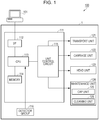
- Fig. 1 is a diagram schematically illustrating a configuration of a printing system 100 according to Embodiment 1.
- Fig. 2 is a plan view schematically illustrating a state of an ink jet type recording apparatus (hereinafter, referred to as a printer) according to the embodiment.
- the printing system 100 is configured to include the printer 1 as an example of a "liquid discharge apparatus", and a computer 101.
- the computer 101 is communicably connected to the printer 1 and outputs print data representing an image to the printer 1.
- the printer based on the print data output from the computer 101, ejects (discharges) an ink 12 (refer to Fig. 2 ) as an example of a "liquid" to a recording medium such as paper or a resin sheet, and records (prints) an image or the like on the recording medium.
- the printer 1 includes a controller 111, a detector group 116, a transport unit 121, a carriage unit 122, a head unit 123, and a maintenance unit 124.
- carriage unit 122 and a cleaning unit 126 are examples of a "moving mechanism”.
- the controller 111 is a control unit for controlling the printer 1.
- the controller 111 includes an interface unit (I/F) 112, a CPU 113, a memory 114, and a unit control circuit 115.
- the interface unit 112 transmits and receives data between the computer 101 and the printer 1.
- the CPU 113 is an arithmetic processing unit for controlling the entire printer 1.
- the memory 114 secures an operation region or a region in which a program of the CPU 113 is stored.
- the CPU 113 controls units 121, 122, 123, and 124 via the unit control circuit 115.
- the detector group 116 monitors a circumstance inside the printer 1 and the CPU 113 controls the units 121, 122, 123, and 124, based on the detection result of the detector group 116.
- the transport unit 121 transports the recording medium to a predetermined position, and the carriage unit 122 causes an ink jet type recording head 10 (hereinafter, referred to as a recording head 10, refer to Fig. 2 ) to move to a predetermined position.
- the head unit 123 includes the recording head 10 that discharges the ink 12 to the recording medium.
- the recording head 10 is an example of a "liquid discharge head”.
- the maintenance unit 124 performs maintenance of the recording head 10 such that the ink 12 is appropriately discharged from the recording head 10, and includes a cap unit 125 and the cleaning unit 126.
- the printer 1 includes a main body frame 2 having a substantially rectangular box shape, and a medium support member 3 is disposed in a longitudinal direction of the main body frame 2 which is a main-scanning direction, in a lower portion in front inside the main body frame 2.
- the medium support member 3 has a substantially rectangular shape and is a support base that supports the recording medium.
- a bar-shaped guide shaft 4 is provided above the medium support member 3 in the main body frame 2 so as to extend to be parallel to the longitudinal direction of the main body frame 2.
- a carriage 5 is supported by the guide shaft 4 in a state in which the carriage is capable of reciprocating along the guide shaft 4.
- the carriage 5 is connected to a carriage motor 7 provided in the main body frame 2, via an endless timing belt 6 that loops between a pair of pulleys 6a provided in the main body frame 2. In this manner, the carriage 5 reciprocates along the guide shaft 4 by the driving of the carriage motor 7.
- the guide shaft 4, the carriage 5, the carriage motor 7, and the pulley 6a configure a part of the carriage unit 122.
- the carriage 5 holds the recording head 10.
- the recording head 10 is able to move in a short direction (sub-scanning direction) of the main body frame 2 by the carriage unit 122.
- the transport unit 121 is capable of transporting the recording medium in a main-scanning direction (short direction of the main body frame 2).
- the sub-scanning direction (short direction of the main body frame 2) is an X direction
- the main-scanning direction (longitudinal direction of the main body frame 2) orthogonal to the sub-scanning direction is a Y direction
- a direction (thickness direction of the main body frame 2) orthogonal to the main-scanning direction and the sub-scanning direction is a Z direction.
- a front end side of an arrow representing a direction in the figures is a "(+) direction” and a base end side thereof is a "(-) direction”.
- a tank holder 9 is provided on one end side of the main body frame 2 in the Y direction, and five ink tanks 8 as liquid supply sources are detachably mounted to the tank holder 9. Different types (colors) of inks are contained in the ink tanks 8, respectively.
- a cyan (C) ink 12C, a magenta (M) ink 12M, a yellow (Y) ink 12Y, a red (R) ink 12R, and a black (K) ink 12K are contained in the ink tanks 8, respectively.
- the number of ink tanks 8 is not limited thereto, one ink tank may be provided, or two or a plurality of ink tanks may be provided.
- the inks 12C, 12M, 12Y, 12R, and 12K are collectively referred to as the ink 12, in some cases.
- the ink 12 contained in the ink tank 8 is pressurized by a pressure feeding unit (not illustrated), and is supplied to the recording head 10 via an ink supply tube 9a and a valve unit (not illustrated).
- a pressure feeding unit include a pressing unit that presses the ink tank 8 from the outside, a pressure pump, and the like.
- the valve unit is a flow path member having a pressure-regulating valve inside and regulates a flow pressure of the ink 12 that is supplied to the recording head 10 such that the ink 12 is stably discharged from nozzles 31 (refer to Fig. 4 ) of the recording head 10.
- a suction unit 50 that suctions the ink 12 from the nozzles 31 of the recording head 10 is provided at a home position region HP of the carriage 5 at a position which is closer to one end portion in the main body frame 2 in the Y direction.
- the suction unit 50 form a part of the cap unit 125, and performs a flushing process in which the ink 12 subjected to a viscosity increase or the ink 12 into which bubbles are mixed is forced to be emitted from the recording head 10.
- a wiping portion 60 to be described below configures a part of the cleaning unit 126, performs a wiping process of removing stains attached to a wiping surface 11 of the recording head 10, and performs a wiping process.
- the wiping portions 60 are provided at two positions in the printer 1. Specifically, a first wiping portion 60A is provided on the X(+) direction side of the home position region HP, and a second wiping portion 60B is provided on the X(-) direction side of the home position region HP.
- the first wiping portion 60A has a first wiper 61A and the second wiping portion 60B has a second wiper 61B.
- the first wiper 61A and the second wiper 61B are formed of an elastic material such as rubber or an elastomer.
- the first wiper 61A and the second wiper 61B are collectively referred to as the wiper 61, in some cases.
- the carriage unit 122 is cable of causing the wiping surface 11 of recording head 10 to move to a predetermined position. In other words, the carriage unit 122 adjusts a position of the wiping surface 11 of the recording head 10.
- the cleaning unit 126 is cable of causing the wiper 61 to move to a predetermined position. Further, the cleaning unit 126 regulates a force (wiping force) of the wiper 61 that is applied to the wiping surface 11 such that the uniform force is applied. In other words, the cleaning unit 126 regulates the position of the wiper 61 and the wiping force of the wiper 61.
- the wiper 61 In the wiping process, while the wiper 61 applies the uniform wiping force to the wiping surface 11 of the recording head 10, the wiper 61 relatively moves with respect to the wiping surface 11 of the recording head 10, thereby removing the stains attached to the wiping surface 11 of the recording head 10.
- the carriage unit 122 and the cleaning unit 126 cause both of the wiper 61 and the recording head 10 to move and cause the wiper 61 to relatively move with respect to the wiping surface 11 of the recording head 10.
- the wiper 61 may be caused to move and the wiper 61 may be caused to relatively move with respect to the wiping surface 11 of the recording head 10. Otherwise, only the recording head 10 may be caused to move and the wiper 61 may be caused to relatively move with respect to the wiping surface 11 of the recording head 10.
- the movement of the wiper 61 with respect to the wiping surface 11 is the same as the relative movement of the wiper 61 with respect to the wiping surface 11, and the movement of the wiper 61 includes the relative movement of the wiper 61.
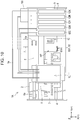
- Fig. 3 is an exploded perspective view of the recording head.
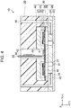
- Fig. 4 is a sectional view of main parts of a head main body taken along line IV-IV in Fig. 2 .
- Fig. 5 is a perspective view of the recording head when viewed from the Z(+) direction side.
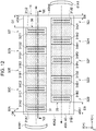
- Fig. 6 is a plan view schematically illustrating a state of the wiping surface when viewed from the Z(+) direction side.
- Fig. 7 is a schematic sectional view taken along line VII-VII in Fig. 5 .
- the recording head 10 includes a head case 20, a plurality of head main bodies 30, and a fixing plate 40.
- the fixing plate 40 is a member that protects a surface of the head case 20 on the Z(+) direction side from being stained with ink droplets or the like.
- the head case 20 is a member that holds (fixes) the head main bodies 30 or the fixing plate 40.
- the fixing plate 40 is provided with openings 41 corresponding to the head main bodies 30, respectively, through which nozzle plates 32 (refer to Fig. 4 ) of the head main bodies 30 are exposed.
- the fixing plate 40 is provided with ten openings 41.
- the openings 41 are opened to be larger than the nozzle plates 32. Note that the openings 41 may be opened to be smaller than the nozzle plates 32 and may adhere to a front surface of the nozzle plates 32 of the fixing plate 40 directly or via another member.
- the fixing plate 40 adheres to a portion other than the nozzle plate 32 of the head main body 30 and is fixed to a surface of the head case 20 on the Z(+) direction side, that is, to the periphery of an opening of a head-main-body holder 25 (refer to Fig. 7 ) via an adhesive or the like.
- the head case 20 is a box-shaped member made of a synthetic resin and has a mounting portion 21 that is connected to an ink supply port of the valve unit.
- the mounting portion 21 is provided with an ink supply needle 19 that is inserted into the ink supply port of the valve unit.
- the head main body 30 has a configuration in which a flow path unit 28, a pressure-generating-chamber forming substrate 29, a vibration plate 38, a piezoelectric element 23, and a protection substrate 48 are stacked in this order, and is attached to the head case 20.
- piezoelectric element 23 is an example of a "drive element”.
- a reservoir 18 is formed inside the head case 20 and supplies the ink 12 to pressure generating chambers 45.
- the reservoir 18 is a space which is common to a plurality of pressure generating chambers 45 which are provided in parallel with each other and in which the ink 12 is stored, and two reservoirs are formed to correspond to two rows of the pressure generating chambers 45 provided in parallel with each other.
- the head case 20 is provided with an ink communicating path 22 (refer to Fig. 7 ) through which the ink 12 is guided to the reservoir 18 from the valve unit.
- a filter (not illustrated) is disposed inside the ink communicating path 22 and removes bubbles or foreign substances in the ink 12.
- the flow path unit 28 has a communication substrate 24 and the nozzle plate 32.
- the communication substrate 24 is a plate member made of silicon.
- a common liquid chamber 43 which communicates with the reservoir 18 and is common to the pressure generating chambers 45, and in which the ink 12 is stored, and individual communication paths 26 through which the ink 12 is supplied to each pressure generating chamber 45, individually, via the common liquid chamber 43 from the reservoir 18.
- the common liquid chamber 43 is an elongated cavity in a nozzle-array direction, and two rows of common liquid chambers are formed to correspond to the two rows of the pressure generating chambers 45 provided to be parallel to each other.
- a plurality of individual communication paths 26 are formed to correspond to the pressure generating chambers 45 in an arrangement direction of the pressure generating chambers 45.
- Nozzle communicating paths 27 are formed at positions corresponding to the nozzles 31 of the communication substrate 24 and penetrate through the communication substrate 24 in a thickness direction.
- the pressure generating chamber 45 and the nozzle 31 communicate with each other through the nozzle communicating path 27.
- the nozzle plate 32 is a silicon substrate that adheres to a surface of the communication substrate 24 on the Z(+) direction side.
- the nozzle plate 32 seals an opening of a space as the common liquid chamber 43 on the Z(+) direction side.
- the nozzle plate 32 is provided with a plurality of nozzles 31 in a straight line shape (row shape). In the embodiment, two rows of nozzles 31 are formed to correspond to the two rows of the pressure generating chambers 45 (refer to Fig. 6 ).
- the nozzle plate can adhere to a region of the communication substrate which projects to the inner side from the common liquid chamber and it is possible to seal the opening of a space as the common liquid chamber on the lower surface side with a member such as a flexible compliance sheet. In this manner, it is possible to decrease the nozzle plate in size to the largest extent.
- the pressure-generating-chamber forming substrate 29 is a silicon substrate that adheres to a surface of the communication substrate 24 on the Z(-) direction side.
- the pressure-generating-chamber forming substrate 29 has a space (cavity) in which the pressure generating chamber 45 is formed.
- the cavity of the pressure-generating-chamber forming substrate 29 and a region surrounded by the vibration plate 38 and the communication substrate 24 form the pressure generating chamber 45.
- the pressure generating chamber 45 is an elongated cavity in a direction orthogonal to the nozzle array direction, the individual communication path 26 communicates with one end portion of the cavity in the longitudinal direction, and the nozzle communicating path 27 communicates with the other end thereof.
- the vibration plate 38 is an elastic thin membrane-like member and is formed on a surface of the pressure-generating-chamber forming substrate 29 on the Z(-) direction side.
- the vibration plate 38 is configured of an elastic membrane made of silicon oxide which is formed on the surface of the pressure-generating-chamber forming substrate 29 on the Z(-) direction side, and an insulation membrane made of zirconium oxide that is formed on the elastic membrane.
- the piezoelectric element 23 is a thin membrane-like piezoelectric device that functions as an actuator which produces a pressure change in the ink 12 in the pressure generating chambers 45, and is formed on the surface of the vibration plate 38 on the Z(-) direction side.
- the piezoelectric element 23 is a piezoelectric device having a so-called flexure mode and is shifted in a receding direction or in an approaching direction from or to the nozzle 31.
- the piezoelectric element 23 may be a piezoelectric device having a longitudinal vibration mode in which the device extends and contracts in an axial direction.
- the piezoelectric element 23 a first electrode 15, a piezoelectric layer 16, and a second electrode 17 are stacked in this order.
- the piezoelectric element 23 means a portion including the first electrode 15, the piezoelectric layer 16, and the second electrode 17.
- the piezoelectric element 23 has a configuration in which one electrode is patterned as a common electrode, the other electrode and the piezoelectric layer 16 are patterned for each pressure generating chamber 45.
- the first electrode 15 is patterned as the common electrode of the piezoelectric element 23 and the second electrode 17 is patterned as an individual electrode of the piezoelectric element 23; however, the patterning may be performed the other way around depending on a drive circuit or wiring.
- the protection substrate 48 for protecting the piezoelectric element 23 adheres to the pressure-generating-chamber forming substrate 29 (vibration plate 38).
- the piezoelectric element 23 is sealed with the pressure-generating-chamber forming substrate 29 and the protection substrate 48, an influence of external water (moisture) is reduced, and thus, degradation of the piezoelectric element 23 due to water is reduced.
- a lead electrode 47 is connected to the second electrodes 17 as the individual electrodes of the piezoelectric element 23 and the lead electrode is pulled out from the vicinity of an end portion on a side opposite to the individual communication path 26 and extends onto the vibration plate 38.
- the head case 20 is provided with a connection port 42 which communicates with a through-hole 49 of the protection substrate 48 and into which a wiring substrate 55 is inserted.
- the wiring substrate 55 is provided with a drive circuit 56 and the wiring substrate 55 inserted into the connection port 42 is connected to the lead electrode 47.
- the ink 12 from the ink tank 8 is guided to the pressure generating chamber 45 via the ink communicating path 22, the reservoir 18, the common liquid chamber 43, and the individual communication path 26. Further, a drive signal from the drive circuit 56 drives the piezoelectric element 23, and the piezoelectric element 23 and the vibration plate 38 are shifted in the receding direction or in the approaching direction from or to the nozzle 31. The pressure change is produced in the pressure generating chamber 45 due to the shift, and the ink 12 is discharged as ink droplets from the nozzles 31 via the nozzle communicating path 27.
- the printer 1 includes the wiper 61, the wiping surface 11 that is wiped with the wiper 61, the plurality of nozzles 31 provided in the wiping surface 11, the piezoelectric element 23 that causes the ink 12 to be discharged from the nozzles 31, and the carriage unit 122 and the cleaning unit 126 that perform relative movement of the wiper 61 and the wiping surface 11.
- the head case 20 is provided with the ink communicating path 22 having one end that is connected to the ink supply port (not illustrated) of the valve unit and the other end that is connected to the reservoir 18.
- a head-main-body holder 25 (recessed portion), inside which the head main body 30 can be accommodated, is provided on a surface of the head case 20 on the Z(+) side facing the recording medium (medium supporting member 3).
- the head-main-body holder 25 is provided individually for each head main body 30 and the head main body 30 is accommodated in the head-main-body holder 25 of the head case 20.
- the head-main-body holder 25 may be provided for the plurality of head main bodies 30.
- the fixing plate 40 and the plurality of nozzle plates 32 are disposed on the surface of the recording head 10 on the Z(+) side facing the recording medium (medium support member 3).
- the wiping surface 11 that is wiped with the wiper 61 is configured of the fixing plate 40 and the plurality of nozzle plates 32.
- the wiping surface 11 is configured of a surface (hereinafter, referred to as a front surface 40A) of the fixing plate 40 on the Z(+) direction side and surfaces (hereinafter, referred to as nozzle formed surfaces 33) of the nozzle plates 32 on the Z(+) direction side in which the plurality of nozzles 31 are formed.
- the wiping surface 11 is configured of a region (region in which the nozzles 31 are arranged) in which the nozzle formed surfaces 33 of the nozzle plates 32 are arranged and a region (region in which no nozzles 31 are arranged) in which the front surface 40A of the fixing plate 40 is disposed.
- the region, in which the nozzle formed surfaces 33 are arranged is an example of a "first region”
- the region, in which the front surface 40A of the fixing plate 40 is disposed is an example of a "second region”.
- the front surface 40A of the fixing plate 40 and the nozzle formed surface 33 are disposed substantially at the same position in the Z direction, and the head-main-body holder 25 is formed such that the wiping surface 11 is flat.
- front surface 40A of the fixing plate 40 and the nozzle formed surface 33 may be disposed at different positions in the Z direction.
- the front surface 40A of the fixing plate 40 has a side 40A1, a side 40A2, a side 40A3, and a side 40A4.
- a surface surrounded by the side 40A1, the side 40A2, the side 40A3, and the side 40A4 is the front surface 40A.
- the side 40A1 is an end of the front surface 40A on the X(-) direction side
- the side 40A2 is an end of the front surface 40A on the Y(-) direction side
- the side 40A3 is an end of the front surface 40A on the X(+) direction side
- the side 40A4 is an end of the front surface 40A on the Y(+) direction side.
- a shaded region represents the front surface 40A of the fixing plate 40 and unshaded region represents the nozzle formed surface 33 of the nozzle plate 32.
- the shaded region is the region, in which the front surface 40A of the fixing plate 40 is disposed, and corresponds to the "second region” in this application.
- the unshaded region is the region, in which the nozzles 31 are arranged, and corresponds to the "first region” in this application.
- the front surface 40A of the fixing plate 40 and the nozzle formed surfaces 33 of ten nozzle plates 32 are arranged on the wiping surface 11 of the recording head 10.
- the ten nozzle plates 32 (nozzle plates 32A, 32B, 32C, 32D, 32E, 32F, 32G, 32H, 321, 32J) are arranged to be closer to one side of the wiping surface 11. Therefore, a distance between the side 40A1 and the ten nozzle plates 32 is different from a distance between the side 40A3 and the nozzle plates, and a distance between the side 40A2 and the nozzle plates is different from a distance between the side 40A4 and the nozzle plates.
- the five nozzle plates 32A, 32C, 32E, 32G, 32I are arranged in this order in the Y direction, and the other five nozzle plates 32B, 32D, 32F, 32H, 32J are arranged in this order in the Y direction.
- the five nozzle plates 32A, 32C, 32E, 32G, 32I and the other five nozzle plates 32B, 32D, 32F, 32H, 32J are arranged not to overlap each other when viewed in the X direction.
- the ten nozzle plates 32 (nozzle plates 32A, 32B, 32C, 32D, 32E, 32F, 32G, 32H, 321, 32J) are arranged in a zigzag pattern.
- the nozzles 31 formed in the five nozzle plates 32A, 32C, 32E, 32G, 32I are arranged to overlap each other when viewed in the Y direction.
- the nozzles 31 formed in the other five nozzle plates 32B, 32D, 32F, 32H, 32J are also arranged to overlap each other.
- some nozzles 31 formed in the five nozzle plates 32A, 32C, 32E, 32G, 321 and some nozzles 31 formed in the other five nozzle plates 32B, 32D, 32F, 32H, 32J may be arranged to overlap each other when viewed in the Y direction.
- Two nozzle arrays in which the plurality of nozzles 31 are arranged in the X direction are formed in the nozzle plate 32.
- two nozzle arrays 31A1 and 31A2 are formed in the nozzle plate 32A.
- Two nozzle arrays 31B1 and 31B2 are formed in the nozzle plate 32B.
- Two nozzle arrays 31C1 and 31C2 are formed in the nozzle plate 32C.
- Two nozzle arrays 31D1 and 31D2 are formed in the nozzle plate 32D.
- Two nozzle arrays 31E1 and 31E2 are formed in the nozzle plate 32E.
- Two nozzle arrays 31F1 and 31F2 are formed in the nozzle plate 32F.
- Two nozzle arrays 31G1 and 31G2 are formed in the nozzle plate 32G.
- Two nozzle arrays 31H1 and 31H2 are formed in the nozzle plate 32H.
- Two nozzle arrays 3111 and 3112 are formed in the nozzle plate 321.
- the arrays are collectively referred to as the nozzle array 310, in some cases.
- the cyan (C) ink 12C is discharged from the nozzle arrays 31A1, 31A2, 31B1, and 31B2, the magenta (M) ink 12M is discharged from the nozzle arrays 31C1, 31C2, 31D1, and 31D2, the yellow (Y) ink 12Y is discharged from the nozzle arrays 31E1, 31E2, 31F1, and 31F2, the red (R) ink 12R is discharged from the nozzle arrays 31G1, 31G2, 31H1, and 31H2, and the black (K) ink 12K is discharged from the nozzle arrays 3111, 3112, 31J1, and 31J2.
- a total of 20 nozzle arrays 310 are arranged in the recording head 10, and the inks 12 of five colors are discharged.
- the colors of the inks 12 that are discharged from the recording head 10 may be smaller than five colors or may be larger than five colors.
- a configuration in which different color inks 12 are discharged from the total 20 nozzle arrays 310, respectively, may be employed. Therefore, in the embodiment, the recording head 10 can discharge the maximum 20 color inks 12.
- the ink 12 contains a color material, water, and a humectant.
- the ink 12 is a water-based ink containing an aqueous solvent.
- the color of the ink 12 is determined depending on the color material.
- the water is a medium that disperses the color material and, for example, it is possible to use pure water or ultrapure water such as ion-exchanged water, ultrafiltration water, reverse osmosis water, or distilled water. Ions or the like may exist in the water to the extent that the ions or the like do not interfere with the dispersion of the color material. Sterilized water subjected to ultraviolet irradiation or by adding hydrogen peroxide reduces an occurrence of mold or bacteria and thus, it is possible to increase stability of the ink 12.
- pure water or ultrapure water such as ion-exchanged water, ultrafiltration water, reverse osmosis water, or distilled water.
- Ions or the like may exist in the water to the extent that the ions or the like do not interfere with the dispersion of the color material.
- Sterilized water subjected to ultraviolet irradiation or by adding hydrogen peroxide reduces an occurrence of mold or bacteria and thus, it is possible to increase stability of
- the humectant plays a role of reducing evaporation (drying of the ink 12) of water.
- the humectant it is possible to use polyhydric alcohols, amino-acid derivatives, pyrrolidone derivatives, saccharides, or the like.
- polyhydric alcohols examples include ethylene glycol, diethylene glycol, triethylene glycol, polyethyleneglycol, polypropylene glycol, propylene glycol, butylene glycol, alkane diol having four to eight carbon atoms such as 1,2-butanediol, 1,2-pentanediol, 1,2-hexanediol, 1,2-heptanediol, 1,2-octanediol, 1,2,6-hexanetriol, thioglycol, hexylene glycol, glycerine, trimethylolethane, trimethylolpropane, glycol ethers, and the like.
- amino-acid derivatives examples include betaines which are N-trialkyl substituent of amino acid such as glycine betaine, atorinine, carnitine, ⁇ -butyrobetaine, trigonelline, ⁇ -alanine betaine, homarine, homoserine betaine, anthopleurin, valine betaine, lysine betaine, ornithine betaine, alanine betaine, taurobetaine, stachydrine, glutamic acid betaine, or phenylalanine betaine.
- betaines which are N-trialkyl substituent of amino acid such as glycine betaine, atorinine, carnitine, ⁇ -butyrobetaine, trigonelline, ⁇ -alanine betaine, homarine, homoserine betaine, anthopleurin, valine betaine, lysine betaine, ornithine betaine, alanine betaine, taurobetaine, stachydrine, glutamic acid be
- pyrrolidone derivatives examples include N-methyl-2-pyrrolidone, N-ethyl-2-pyrrolidone, N-vinyl-2-pyrrolidone, 2-pyrrolidone, N-butyl-2-pyrrolidone, 5-methyl-2-pyrrolidone, polyvinylpyrrolidone, and the like.
- Examples of the saccharides include monosaccharides, oligosaccharides, and polysaccharides.
- examples of the saccharides include glucose, mannose, galactose, fucose, ribose, fructose, xylose, arabinose, maltose, cellobiose, lactose, sucrose, trehalose, raffinose, panose, YI maltose, stachyose, gentiobiose, gentianose, and the like.
- glycerin is used as the humectant.
- the glycerin has high hygroscopicity.
- the glycerin is added to the ink 12, thereby, evaporation of water is reduced and thus, it is possible to increase the stability of the ink 12.
- the ink 12 since the glycerin has a viscosity higher than the water, the ink 12 has a low viscosity when a glycerin content rate (an amount of glycerin added into the ink 12) of the ink 12 is decreased. The ink 12 has a high viscosity when the glycerin content rate of the ink 12 is increased.
- the glycerin content rates of the inks 12 are decreased in the order from the ink 12C, the ink 12M, the ink 12Y, the ink 12R, to the ink 12K.
- the viscosity of the ink 12 is decreased in the order from the ink 12C, the ink 12M, the ink 12Y, the ink 12R, to the ink 12K.
- the glycerin content rates of the inks 12 that are discharged from the nozzle plates 32 and the viscosity of the inks 12 that are discharged from the nozzle plates 32 are decreased in the order from the nozzle plate 32A, the nozzle plate 32C, the nozzle plate 32E, the nozzle plate 32G, to the nozzle plate 321 of the five nozzle plates 32A, 32C, 32E, 32G, and 321 arranged in the Y direction.
- the glycerin content rates of the inks 12 that are discharged from the nozzle plates 32 and the viscosity of the inks 12 that are discharged from the nozzle plates 32 are decreased in the order from the nozzle plate 32B, the nozzle plate 32D, and the nozzle plate 32F, the nozzle plate 32H, to the nozzle plate 32J of the five nozzle plates 32B, 32D, 32F, 32H, and 32J arranged in the Y direction.
- Fig. 8 is a view corresponding to Fig. 6 , and is a plan view schematically illustrating a state of the wiping process.
- Fig. 9 is a schematic sectional view taken along line IX-IX in Fig. 8 , and a view schematically illustrating a state of the wiping process.
- both of the ink droplet discharge operation in which the ink 12 is discharged as the ink droplets from the nozzles 31 of the recording head 10, and a transport operation of the recording medium are alternately repeated, and thereby a desired image is printed on the recording medium.
- ink mist is attached to the front surface 40A of the fixing plate 40 or to the nozzle formed surface 33 of the nozzle plate 32 and stains the wiping surface 11. Further, dust or lint that floats around the recording head 10 is attached to the front surface 40A of the fixing plate 40 or to the nozzle formed surface 33 of the nozzle plate 32 and stains the wiping surface 11.
- the ink mists (ink 12), in which dust or lint is mixed, are accumulated on the wiping surface 11 as a stain 63 (refer to Fig. 9 ).
- the stains 63 are accumulated on the wiping surface 11 (especially, the nozzle formed surface 33)
- uniformity of the ink discharge performance of the recording head 10 is degraded and thus, a quality of an image that is printed on the recording medium is degraded. Therefore, in the printer 1, a flushing process or the wiping process, in which the stains 63 accumulated on the wiping surface 11 are removed, is regularly performed, and the recording head 10 returns to a normal state.
- the ink 12, of which the properties are degraded (the ink 12 subjected to a viscosity increase or the ink 12 into which bubbles are mixed), is forced to be emitted from the nozzles 31 of the recording head 10. Further, in the flushing process, the ink 12, of which the properties are not degraded, is also discharged, in addition to the ink 12 of which the properties are degraded. Further, the stains 63 attached to the nozzle formed surface 33 are removed along with the ink 12 that is forced to be discharged from the nozzles 31. Therefore, after the flushing process is ended, the ink 12, of which the properties are not degraded, is attached on the nozzle formed surface 33.
- the wiping process is performed after the flushing process, the wiping surface 11 is wiped with the wiper 61, and the stains 63 attached on the front surface 40A of the fixing plate 40 or the ink 12 attached to the nozzle formed surface 33, of which the properties are not degraded, are removed.
- the recording head 10 returns to the normal state, the recording head 10 performs a normal operation, and defective printing by the printer 1 is reduced.
- Fig. 8 for easy understanding of the state of the wiping process, the wiping surface 11 (the front surface 40A of the fixing plate 40 and the nozzle formed surfaces 33 of the nozzle plates 32), the wipers 61A and 61B are illustrated, and the other components are omitted. Further, an arrow represents a moving direction of the wipers 61A and 61B with respect to the wiping surface 11.
- reference sign 31J2A is assigned to the nozzle 31 disposed to be closest to the side 40A1 in the nozzle plate 32J
- reference sign 31J2B is assigned to the nozzle 31 disposed to be farthest from the side 40A1.
- Reference sign 31I2A is assigned to the nozzle 31 disposed to be closest to the side 40A3 in the nozzle plate 321
- reference sign 31I2B is assigned to the nozzle 31 disposed to be farthest from the side 40A3.
- the nozzle plate 32J is an example of a "first nozzle plate” and the nozzle plate 32I is an example of a "second nozzle plate”.
- the moving direction (X(+) direction) of the first wiper 61A represented by an arrow in Fig. 8 and the moving direction (X(-) direction) of the second wiper 61B represented by an arrow in Fig. 8 are examples of a "moving direction of a wiper with respect to the wiping surface".
- the side 40A1 is an example of an "edge on the upstream side in the moving direction” and an “edge of the wiping surface on a side closer to the nozzle region" in the moving direction (X(+) direction) of the first wiper 61A with respect to the wiping surface 11.
- the side 40A3 is an example of an "edge on the downstream side in the moving direction” and an “edge of the wiping surface on a side farther from the nozzle region”.
- the nozzle 31J2A is an example of a "nozzle disposed on the upstream side”
- the nozzle 31J2B is an example of a "nozzle disposed on the downstream side”.
- the side 40A3 is an example of an "edge on the upstream side in the moving direction” and an “edge of the wiping surface on a side closer to the nozzle region" in the moving direction (X(-) direction) of the second wiper 61B with respect to the wiping surface 11.
- the side 40A1 is an example of an "edge on the downstream side in the moving direction” and an “edge of the wiping surface on a side farther from the nozzle region”.
- the nozzle 32I2A is an example of a "nozzle disposed on the upstream side”
- the nozzle 31I2B is an example of a "nozzle disposed on the downstream side”.
- a distance D1 between the side 40A1 and the nozzle 31J2A is shorter than a distance D2 between the side 40A3 and the nozzle 31J2B. Further, a distance D3 between the side 40A3 and the nozzle 31I2A is shorter than a distance D4 between the side 40A1 and the nozzle 31I2B.
- the distance D1 and the distance D3 are examples of a "distance between an edge of the wiping surface on the upstream side in the moving direction and a nozzle disposed on the upstream side".
- the distance D2 and the distance D4 are examples of a "distance between an edge of the wiping surface on the downstream side in the moving direction and a nozzle disposed on the downstream side”.
- the first wiper 61A moves in the X(+) direction with respect to the wiping surface 11 and wipes the nozzle formed surface 33 of the nozzle plate 32J.
- the second wiper 61B moves in the X(-) direction with respect to the wiping surface 11 and wipes the nozzle formed surface 33 of the nozzle plate 321.
- the wiping surface 11 have the first nozzle plate (nozzle plate 32J) and the second nozzle plate (nozzle plate 321) in which the nozzles 31 are formed, and the first wiper 61A wipes the first nozzle plate (nozzle plate 32J) and the second wiper 61B wipes the second nozzle plate (nozzle plate 321).
- the first wiper 61A first comes into contact with the side 40A1 of the wiping surface 11, moves in the X(+) direction with respect to the wiping surface 11, and then is separated from the side 40A3 of the wiping surface 11.
- the second wiper 61B first comes into contact with the side 40A3 of the wiping surface 11, moves in the X(-) direction with respect to the wiping surface 11, and then is separated from the side 40A1 of the wiping surface 11.
- the “edge of the wiping surface on the upstream side in the moving direction” in the application corresponds to a portion of the wiping surface 11 with which the wiper 61 first comes into contact.
- the “edge of the wiping surface on the downstream side in the moving direction” in the application corresponds to a portion of the wiping surface 11 from which the wiper 61 is separated.
- the side 40A1 corresponds to the "edge on the upstream side".
- the "edge on the upstream side” is disposed in a region between the side 40A1 of the front surface 40A and the nozzle plate 32J.
- the side 40A3 corresponds to the "edge on the downstream side".
- the "edge on the downstream side” is disposed in a region between the side 40A3 of the front surface 40A and the nozzle plate 32J.
- the side 40A3 corresponds to the "edge on the upstream side".
- the "edge on the upstream side” is disposed in a region between the side 40A3 of the front surface 40A and the nozzle plate 321.
- the side 40A1 corresponds to the "edge on the downstream side".
- the "edge on the downstream side” is disposed in a region between the side 40A1 of the front surface 40A and the nozzle plate 321.
- the wiping surface 11 has the first nozzle plate (nozzle plate 32J) and the second nozzle plate (nozzle plate 32I) in which the nozzles 31 are formed, and the wiper 61 includes the first wiper 61A that wipes the first nozzle plate (nozzle plate 32J) and the second wiper 61B that wipes the second nozzle plate (nozzle plate 321).
- the first wiper 61A is caused to move in the moving direction of the first wiper 61A with respect to the wiping surface 11, in the state in which the distance D1 between the edge (side 40A1) of the wiping surface 11 on the upstream side in the moving direction and the nozzle 31J2A disposed on the upstream side is shorter than the distance D2 between the edge (side 40A3) of the wiping surface 11 on the downstream side in the moving direction and the nozzle 31J2B disposed on the downstream side, and the first wiper wipes the wiping surface 11.
- the second wiper 61B is caused to move in the moving direction of the second wiper 61B with respect to the wiping surface 11, in the state in which the distance D3 between the edge (side 40A3) of the wiping surface 11 on the upstream side in the moving direction and the nozzle 31I2A disposed on the upstream side is shorter than the distance D4 between the edge (side 40A1) of the wiping surface 11 on the downstream side in the moving direction and the nozzle 31I2B disposed on the downstream side, and the second wiper wipes the wiping surface 11.
- the first wiper 61A is caused to move in a direction from the edge (side 40A1) of the wiping surface 11 which is closer to the nozzle region (nozzle plate 32J) toward the edge (side 40A3) of the wiping surface 11 which is farther from the nozzle region (nozzle plate 32J), and the first wiper wipes the wiping surface 11.
- the second wiper 61B is caused to move in a direction from the edge (side 40A3) of the wiping surface 11 which is closer to the nozzle region (nozzle plate 321) toward the edge (side 40A1) of the wiping surface 11 which is farther from the nozzle region (nozzle plate 321), and the second wiper wipes the wiping surface 11.
- the first wiper 61A is caused to move in the Y(-) direction and the nozzle formed surface 33 of the nozzle plate 32H is wiped with the first wiper 61A.
- the second wiper 61B is caused to move in the Y(-) direction and the nozzle formed surface 33 of the nozzle plate 32G is wiped with the second wiper 61B.
- the first wiper 61A is caused to move in the Y(-) direction and the nozzle formed surface 33 of the nozzle plate 32F is wiped with the first wiper 61A.
- the second wiper 61B is caused to move in the Y(-) direction and the nozzle formed surface 33 of the nozzle plate 32E is wiped with the second wiper 61B.
- the first wiper 61A is caused to move in the Y(-) direction and the nozzle formed surface 33 of the nozzle plate 32D is wiped with the first wiper 61A.
- the second wiper 61B is caused to move in the Y(-) direction and the nozzle formed surface 33 of the nozzle plate 32C is wiped with the second wiper 61B.
- the first wiper 61A is caused to move in the Y(-) direction and the nozzle formed surface 33 of the nozzle plate 32B is wiped with the first wiper 61A.
- the second wiper 61B is caused to move in the Y(-) direction and the nozzle formed surface 33 of the nozzle plate 32A is wiped with the second wiper 61B.
- the wiping methods in the next wiping processes and the final wiping process are the same as the wiping method in the first wiping process.
- the wiping surface 11 has the plurality of nozzle plates 32 in which the nozzles 31 are formed, and the nozzle plates 32 are arranged in the zigzag pattern.
- the nozzle plates 32 are arranged at positions which are closer to the edge of the wiping surface 11 on the upstream side than the edge of the wiping surface 11 on the downstream side in the moving direction of the wiper 61 with respect to the wiping surface 11.
- the wiper 61 is caused to move in the direction from the edge of the wiping surface 11 on the upstream side toward the edge of the wiping surface 11 on the downstream side, and the wiping surface 11 is wiped.
- the wiping method according to the embodiment described above is not limited to the application to the water-based ink (ink 12) containing the aqueous solvent, and it is possible to apply to another ink such as a non-aqueous that does not contain the aqueous solvent but contains an organic solvent.
- the first wiper 61A wipes the nozzles 31 which discharge the ink 12 having the low glycerin content rate, and then wipes the nozzles 31 from which the ink 12 having the high glycerin content rate is discharged.
- the second wiper 61B wipes the nozzles 31 which discharge the ink 12 having the low glycerin content rate, and then wipes the nozzles 31 from which the ink 12 having the high glycerin content rate is discharged.
- the embodiment has a configuration in which the wiper 61 wipes the nozzles 31 which discharge the ink 12 having the low humectant (glycerin) content rate of the inks 12, and then wipes the nozzles 31 that discharge the ink 12 having the high humectant (glycerin) content rate of the inks 12.
- the first wiper 61A moves with respect to the wiping surface 11 at a speed which becomes slower in the order from the nozzle plate 32J, the nozzle plate 32H, the nozzle plate 32F, the nozzle plate 32D, the nozzle plate 32B, to the front surface 40A of the fixing plate 40.
- the first wiper 61A moves with respect to the wiping surface 11 at the speed which becomes slower on the side closer to the front surface 40A of the fixing plate 40 and becomes faster on the side closer to the nozzle plates 32.
- the second wiper 61B moves with respect to the wiping surface 11 at a speed which becomes slower in the order from the nozzle plate 321, the nozzle plate 32G, the nozzle plate 32E, the nozzle plate 32C, the nozzle plate 32A, to the front surface 40A of the fixing plate 40.
- the second wiper 61B moves with respect to the wiping surface 11 at the speed which becomes slower on the side closer to the front surface 40A of the fixing plate 40 and becomes faster on the side closer to the nozzle plates 32.
- the embodiment has a configuration in which the wiper 61 moves with respect to the wiping surface 11 at a slower speed in the region in which the front surface 40A of the fixing plate 40 is disposed than in the region in which the nozzles 31 are arranged.
- the first wiper 61A moves with respect to the wiping surface 11 at a faster speed on the side closer to the nozzle plate 32 from which the ink 12 having the low viscosity is discharged, and at a slower speed on the side closer to the nozzle plate 32 from which the ink 12 having the high viscosity is discharged.
- the second wiper 61B moves with respect to the wiping surface 11 at a faster speed on the side closer to the nozzle plate 32 from which the ink 12 having the low viscosity is discharged, and at a slower speed on the side closer to the nozzle plate 32 from which the ink 12 having the high viscosity is discharged.
- the embodiment has a configuration in which the wiper 61 moves with respect to the wiping surface 11 at the slower speed on the nozzle plate 32 side in which the nozzles 31 that discharge the ink 12 having the high viscosity of the inks 12 are formed than on the nozzle plate 32 side in which the nozzles 31 that discharge the ink 12 having the low viscosity of the inks 12 are formed.
- a length WA of the first wiper 61A in the Y direction and a length WB of the second wiper 61B in the Y direction are shorter than a length W of the wiping surface 11 in the Y direction.
- the length WA of the first wiper 61A in the Y direction and the length WB of the second wiper 61B in the Y direction are examples of a "length of the wiper in a direction intersecting with the moving direction".
- the length W of the wiping surface 11 in the Y direction is an example of a "length of the wiping surface in the direction intersecting with the moving direction”.
- the first wiper 61A and the second wiper 61B in the Y direction are shorter than the length W of the wiping surface 11 in the Y direction, the first wiper 61A and the second wiper 61B moves from the edge of the wiping surface 11 on the upstream side to the edge of the wiping surface 11 on the downstream side a plurality of times, and the entire wiping surface 11 is wiped.
- the first wiper 61A moves in the X(+) direction five times and wipes the wiping surface 11.
- the second wiper 61B moves in the X(-) direction five times and wipes the wiping surface 11.
- the first wiper 61A can wipe the entire wiping surface 11 through the wiping process performed once.
- the wiping surface 11 be wiped a plurality of times such that appropriate wiping processes are performed on the regions on which different appropriate wiping processes need to be performed.
- Fig. 9 is a schematic sectional view taken along line IX-IX in Fig. 8 , and a view schematically illustrating a state of the first wiping process by using the first wiper.
- a gap between the fixing plate 40 and the nozzle plate 32J is omitted.
- the stains 63 are attached to the front surface 40A of the fixing plate 40.
- the stains 63 are the ink 12 (ink 12 from which the solvent component is evaporated) in which dust or lint is mixed and which is subjected to the viscosity increase.
- the number of attachment of the stains 63 to the front surface 40A of the fixing plate 40 is proportional to an area of the front surface 40A of the fixing plate 40. Since an area of the front surface 40A which is disposed between the side 40A3 and the nozzle plate 32J is broader than an area of the front surface 40A which is disposed between the side 40A1 and the nozzle plate 32J, the number of attachment of the stains 63 is larger on the front surface 40A side which is disposed between the 40A3 and the nozzle plate 32J, and is smaller on the front surface 40A side which is disposed between the 40A1 and the nozzle plate 32J.
- the stains 63 are removed from the nozzle formed surface 33 of the nozzle plate 32J through the flushing process and the ink 12 (ink 12 which is not subjected to the viscosity increase), of which the properties are not degraded, is attached to the nozzle formed surface 33 of the nozzle plate 32J.
- the first wiper 61A is caused to move in the direction (X(+) direction) from the side 40A1 toward the side 40A3, and removes the stains 63 attached to the front surface 40A of the fixing plate 40 and the ink 12 which is attached to the nozzle formed surface 33 of the nozzle plate 32J and is not subjected to the viscosity increase.
- the first wiper 61A is caused to move from a side, on which a small amount of the stains 63 is attached to the front surface 40A of the fixing plate 40, toward a side, on which a large amount of the stains 63 is attached to the front surface 40A of the fixing plate 40, the first wiper removes the stains 63 attached to the front surface 40A of the fixing plate 40 and the ink 12 which is attached to the nozzle formed surface 33 of the nozzle plate 32J and is not subjected to the viscosity increase.
- the first wiper 61A is caused to move in a direction from the side, on which the small amount of the stains 63 is attached to the front surface 40A of the fixing plate 40, toward the side, on which the large amount of the stains 63 is attached to the front surface 40A of the fixing plate 40, a small amount of the stains 63 moves along with the first wiper 61A. Therefore, the stains 63 are not likely to be rubbed into the nozzles 31 of the nozzle plate 32J and the problem of abnormal discharge of the inks 12 from the nozzles 31 is not likely to arise.
- the first wiper 61A be caused to move in the direction from the edge (side 40A1) of the wiping surface 11 which is closer to the nozzle region (nozzle plate 32J) toward the edge (side 40A3) of the wiping surface 11 which is farther from the nozzle region (nozzle plate 32J), and the first wiper 61A remove the stains 63 attached to the wiping surface 11.
- the first wiper 61A be caused to move with respect to the wiping surface 11 in the moving direction of the first wiper 61A with respect to the wiping surface 11, in the state in which the distance D1 between the edge (side 40A1) of the wiping surface 11 on the upstream side in the moving direction and the nozzle 31J2A disposed on the upstream side is shorter than the distance D2 between the edge (side 40A3) of the wiping surface 11 on the downstream side in the moving direction and the nozzle 31J2B disposed on the downstream side, and the first wiper 61A remove the stains 63 attached to the wiping surface 11.
- the stains 63 (ink 12 subjected to the viscosity increase) attached to the front surface 40A of the fixing plate 40 are firmly attached, compared to the ink 12 which is attached to the nozzle formed surface 33 of the nozzle plate 32J and is not subjected to the viscosity increase.
- the ink 12, which is attached to the nozzle formed surface 33 of the nozzle plate 32J and is not subjected to the viscosity increase, is loosely attached, compared to the stains 63 (ink 12 subjected to the viscosity increase) attached to the front surface 40A of the fixing plate 40.
- the stains 63 need to be strongly wiped, the wiper 61 need to have a high capability of removing the stains, and the stains 63 need to be removed from the front surface 40A of the fixing plate 40.
- the wiper 61 is caused to move with respect to the wiping surface 11.
- the strong wiping mean that the wiping force is applied for a long time, and when the wiping force is applied for a long time, the capability of the wiper 61 of removing the stains (stains 63 or the ink 12) is increased.
- the weak wiping mean that the wiping force is applied for a short time, and when the wiping force is applied for a short time, the capability of the wiper 61 of removing the stains (stains 63 or the ink 12) is decreased.
- the first wiper 61A moves with respect to the wiping surface 11 at the slower speed on the side closer to the front surface 40A of the fixing plate 40 than on the side closer to the nozzle plates 32, the wiping force is applied for a long time, and the stains 63 firmly attached to the front surface 40A of the fixing plate 40 is removed.
- the first wiper 61A move with respect to the wiping surface 11 at the slower speed on the side closer to the front surface 40A of the fixing plate 40 than on the side closer to the nozzle plates 32, and the wiping force be applied to the stains 63 attached to the front surface 40A of the fixing plate 40 for a long time.
- the first wiper 61A move with respect to the wiping surface 11 at a slower speed in a region (the front surface 40A of the fixing plate 40) in which no nozzles 31 are arranged, than in a region (the nozzle formed surfaces 33 of the nozzle plates 32) in which the nozzles 31 are arranged.
- the first wiper 61A moves with respect to the wiping surface 11 at the faster speed on the side closer to the nozzle plates 32 than on the side closer to the front surface 40A of the fixing plate 40, the wiping force is applied for a short time, and the ink 12, which is weakly attached to the nozzle formed surface 33 of the nozzle plate 32J and is not subjected to the viscosity increase, is removed.
- the wiping is performed on the nozzle formed surface 33 of the nozzle plate 32J for a short time and it is possible to efficiently perform the wiping process.
- the viscosity of the inks 12 that are discharged from the nozzle plates 32 is decreased in the order from the nozzle plate 32B, the nozzle plate 32D, the nozzle plate 32F, the nozzle plate 32H, to the nozzle plate 32J
- the viscosity of the inks 12, which are attached to the nozzle formed surfaces 33 of the nozzle plates 32 and is not subjected to the viscosity increase is also decreased in the order from the nozzle plate 32B, the nozzle plate 32D, the nozzle plate 32F, the nozzle plate 32H, to the nozzle plate 32J.
- the ink 12 having the low viscosity is easy to flow, compared to the ink 12 having the high viscosity, it is possible to remove the ink from the nozzle formed surfaces 33 of the nozzle plates 32 even through weak wiping. Since the ink 12 having the high viscosity is difficult to flow, compared to the ink 12 having the low viscosity, the ink needs to be removed from the nozzle formed surfaces 33 of the nozzle plates 32 through strong wiping.
- the wiping force be applied to the ink 12 having the high viscosity for a long time, compared to the ink 12 having the low viscosity, and strong wiping be performed.
- the first wiper 61A move at the speed which becomes slower in the order from the nozzle plate 32J, the nozzle plate 32H, the nozzle plate 32F, the nozzle plate 32D, and the nozzle plate 32B.
- the first wiper 61A move with respect to the wiping surface 11 at the slower speed on the nozzle plate 32 side in which the nozzles 31 that discharge the ink 12 having the high viscosity of the inks 12 are formed than on the nozzle plate 32 side in which the nozzles 31 that discharge the ink 12 having the low viscosity of the inks 12 are formed.
- the first wiper 61A moves with respect to the wiping surface 11 at the faster speed on the side closer to the nozzle plate 32 in which the nozzles 31 that discharge the ink 12 having the low viscosity are formed, thereby, the wiping time is shortened, and it is possible to efficiently perform the wiping process.
- the preferable wiping process and the reason thereof is described, as an example, with the first wiping process in which the first wiper 61A is used. Since the preferable wiping process and the reason described above is the same as the first wiping process, the next wiping process, and the final wiping process by using the second wiper 61B, the description thereof is omitted.
- Fig. 10 is a plan view schematically illustrating a state of a printer according to Embodiment 2.
- Fig. 11 is a view corresponding to Fig. 8 , and is a plan view schematically illustrating the state of the wiping process.
- the wiping portion 60 is provided at one position in the printer 1A according to the present embodiment.
- the wiping portion 60 is provided at two positions in the printer 1 according to Embodiment 1. This is a difference between the present embodiment and Embodiment 1.
- the printer 1A according to the present embodiment is described by focusing on the differences from the printer 1 according to Embodiment 1, with reference to Figs. 10 and 11 .
- the same reference signs are assigned to the same components as those in Embodiment 1, and repeated description thereof is omitted.
- the wiping portion 60 is provided on the X(+) direction side of the home position region HP.
- the wiping portion 60 has a wiper 61.
- the carriage unit 122 is cable of causing the wiping surface 11 of recording head 10 to move to a predetermined position.
- the cleaning unit 126 is cable of causing the wiper 61 to move to a predetermined position.
- the wiper 61 is capable of moving in any direction with the cleaning unit 126, and is rotatable, the wiper moves with respect to the wiping surface 11 of the recording head 10 while the wiper causes the uniform wiping force to be applied such that the stains attached to the wiping surface 11 of the recording head 10 are removed.
- the wiper 61 moves in a direction represented by an arrow having two-dot chain line in Fig. 11 , wipes in the order from the nozzle formed surface 33 of the nozzle plate 32J, the nozzle formed surface 33 of the nozzle plate 32I, the nozzle formed surface 33 of the nozzle plate 32H, the nozzle formed surface 33 of the nozzle plate 32G, the nozzle formed surface 33 of the nozzle plate 32F, the nozzle formed surface 33 of the nozzle plate 32E, the nozzle formed surface 33 of the nozzle plate 32D, the nozzle formed surface 33 of the nozzle plate 32C, the nozzle formed surface 33 of the nozzle plate 32B, and the nozzle formed surface 33 of the nozzle plate 32A.
- the wiper 61 wipes the nozzle formed surface 33 of the nozzle plate 32J and is reversed, and the wiper 61 wipes the nozzle formed surface 33 of the nozzle plate 32I and is reversed. Subsequently, the wiper 61 wipes the nozzle formed surface 33 of the nozzle plate 32H and is reversed, and the wiper 61 wipes the nozzle formed surface 33 of the nozzle plate 32G and is reversed. Subsequently, the wiper 61 wipes the nozzle formed surface 33 of the nozzle plate 32F and is reversed, and the wiper 61 wipes the nozzle formed surface 33 of the nozzle plate 32E and is reversed.
- the wiper 61 wipes the nozzle formed surface 33 of the nozzle plate 32D and is reversed, and the wiper 61 wipes the nozzle formed surface 33 of the nozzle plate 32C and is reversed. Subsequently, the wiper 61 wipes the nozzle formed surface 33 of the nozzle plate 32B and is reversed, and the wiper 61 wipes the nozzle formed surface 33 of the nozzle plate 32A and is reversed.
- the wiping surface 11 has the first nozzle plate (nozzle plate 32J) and the second nozzle plate (nozzle plate 32I) in which the nozzles 31 are formed, and the wiper 61 wipes the first nozzle plate (nozzle plate 32J), and then wipes the second nozzle plate (nozzle plate 32I).
- the wiping surface 11 have the first nozzle plate (nozzle plate 32J) and the second nozzle plate (nozzle plate 32I) in which the nozzles 31 are formed, and the first wiper 61A wipes the first nozzle plate (nozzle plate 32J) and the second wiper 61B wipes the second nozzle plate (nozzle plate 32I).
- one wiper 61 (one wiping portion 60) performs the wiping process and, in Embodiment 1, the two wipers 61A and 61B (two wiping portions 60) perform the wiping process.
- a mechanism of a portion that performs the wiping is more simplified, compared to Embodiment 1, and the portion that performs the wiping can be produced in low costs and has a compact size.
- the wiping process is performed by the same wiping method as Embodiment 1.
- the wiper 61 is caused to move in the direction from the edge of the wiping surface 11 which is closer to the nozzle region (nozzle plate 32) toward the edge of the wiping surface 11 which is farther from the nozzle region (nozzle plate 32), and the wiper wipes the wiping surface 11.
- the wiper 61 is caused to move with respect to the wiping surface 11 in the moving direction of the wiper 61 with respect to the wiping surface 11, in the state in which the distance between the edge of the wiping surface 11 on the upstream side in the moving direction and the nozzle 31 disposed on the upstream side is shorter than the distance between the edge of the wiping surface 11 on the downstream side in the moving direction and the nozzle 31 disposed on the downstream side, and the wiper wipes the wiping surface 11.
- the wiper 61 wipes the nozzles 31 which discharge the ink 12 having the low glycerin content rate, and then wipes the nozzles 31 which discharge the ink 12 having the high glycerin content rate.
- the wiping process is performed such that the wiper 61 moves with respect to the wiping surface 11 at a slower speed in the region (the front surface 40A of the fixing plate 40) in which no nozzles 31 are arranged, than in the region (the nozzle formed surfaces 33 of the nozzle plates 32) in which the nozzles 31 are arranged.
- the wiping process is performed such that the wiper 61 moves with respect to the wiping surface 11 at the slower speed on the nozzle plate 32 side in which the nozzles 31 that discharge the ink 12 having the high viscosity of the inks 12 are formed than on the nozzle plate 32 side in which the nozzles 31 that discharge the ink 12 having the low viscosity of the inks 12 are formed.
- Fig. 12 is a view corresponding to Fig. 8 , and is a plan view schematically illustrating the state of the wiping process in a printer according to Embodiment 3.
- Fig. 13 is a schematic sectional view taken along line XIII-XIII in Fig. 12 .
- the moving direction of the wiper 61 with respect to the wiping surface 11 is different from that in the printer 1 according to Embodiment 1.
- the present embodiment differs from Embodiment 1 in that the wiper moves in the Y direction in the present embodiment, and the wiper moves in the X direction in Embodiment 1.
- the wiping process of the printer according to the present embodiment is described by focusing on the differences from the printer 1 according to Embodiment 1, with reference to Figs. 12 and 13 .
- the same reference signs are assigned to the same components as those in the Embodiment 1, and repeated description thereof is omitted.
- first wiper 61A1 moves in the Y(-) direction and wipes the first nozzle plate group 35.
- the second wiper 61B1 moves in the Y(+) direction and wipes the second nozzle plate group 36.
- the first nozzle plate group 35 is disposed on the wiping surface 11 such that a distance D8 between the side 40A4 and the nozzle plate 32J is shorter than a distance D9 between the side 40A2 and the nozzle plate 32B. Further, the second nozzle plate group 36 is disposed on the wiping surface 11 such that a distance D6 between the side 40A2 and the nozzle plate 32A is shorter than a distance D7 between the side 40A4 and the nozzle plate 32I.
- the nozzle plate 32J is an example of the "first nozzle plate” and the nozzle plates 32H, 32F, 32D, and 32B are examples of the "second nozzle plate”.
- the side 40A4 is an example of the "edge on the upstream side in the moving direction”.
- the side 40A2 is an example of the "edge on the downstream side in the moving direction”.
- the nozzle plate 32A is an example of the "first nozzle plate” and the nozzle plates 32C, 32E, 32G, and 32I are examples of the "second nozzle plate”.
- the side 40A2 is an example of the "edge on the upstream side in the moving direction”.
- the side 40A4 is an example of the "edge on the downstream side in the moving direction”.
- the present embodiment has a configuration in which the wiping surface 11 has the first nozzle plate group 35 including the first nozzle plate (nozzle plate 32J) and the second nozzle plates (nozzle plates 32H, 32F, 32D, and 32B) in which the nozzles 31 are formed and which are arranged in the moving direction (Y(-) direction) of the first wiper 61A1 with respect to the wiping surface 11, and the first nozzle plate group 35 is disposed at a position which is closer to the edge (side 40A4) of the wiping surface 11 on the upstream side than to the edge (side 40A2) of the wiping surface on the downstream side in the moving direction (Y(-) direction).
- the first wiper 61A1 wipes the first nozzle plate group 35 in the moving direction (Y(-) direction).
- the present embodiment has a configuration in which the wiping surface 11 has the second nozzle plate group 36 including the first nozzle plate (nozzle plate 32A) and the second nozzle plates (nozzle plates 32C, 32E, 32G, and 32I) in which the nozzles 31 are formed and which are arranged in the moving direction (Y(+) direction) of the second wiper 61B1 with respect to the wiping surface 11, and the second nozzle plate group 36 is disposed at a position which is closer to the edge (side 40A2) of the wiping surface 11 on the upstream side than to the edge (side 40A4) of the wiping surface on the downstream side in the moving direction (Y(+) direction).
- the second wiper 61B1 wipes the second nozzle plate group 36 in the moving direction (Y(+) direction).
- widths of the wipers 61A1 and 61B1 are larger than widths of the wipers 61A and 61B of Embodiment 1 (size of the wiper 61 in the direction intersecting with the moving direction). This is another difference between the present embodiment and Embodiment 1.
- the first wiper 61A1 moves with respect to the wiping surface 11 in the Y(-) direction and the nozzle plate 32J, the nozzle plate 32H, the nozzle plate 32F, the nozzle plate 32D, and the nozzle plate 32B are wiped in this order. In other words, the first wiper 61A1 moves with respect to the wiping surface 11 in the Y(-) direction once and wipes the wiping surface 11.
- the first wiper 61A of Embodiment 1 moves in the X(+) direction five times and wipes the wiping surface 11.
- the second wiper 61B1 moves with respect to the wiping surface 11 in the Y(+) direction and the nozzle plate 32A, the nozzle plate 32C, the nozzle plate 32E, the nozzle plate 32G, and the nozzle plate 321 are wiped in this order. In other words, the second wiper 61B1 moves with respect to the wiping surface 11 in the Y(+) direction once and wipes the wiping surface 11.
- the second wiper 61B of Embodiment 1 moves in the X(-) direction five times and wipes the wiping surface 11.
- the cyan (C) ink 12C is discharged from the nozzle plates 32A and 32B, the magenta (M) ink 12M is discharged from the nozzle plates 32C and 32D, the yellow (Y) ink 12Y is discharged from the nozzle plates 32E and 32F, the red (R) ink 12R is discharged from the nozzle plates 32G and 32H, and the black (K) ink 12K is discharged from the nozzle plates 321 and 32J.
- M magenta
- Y yellow
- R red
- K black
- the glycerin content rates of the inks 12 which are discharged from the first nozzle plate group 35 are decreased in the order from the cyan (C) ink 12C, the magenta (M) ink 12M, the yellow (Y) ink 12Y, the red (R) ink 12R, to the black (K) ink 12K.
- the glycerin content rates of the inks 12 which are discharged from the nozzle plates 32 are decreased in the order from the nozzle plate 32B, the nozzle plate 32D, the nozzle plate 32F, the nozzle plate 32H, to the nozzle plate 32J. This is the same both in the present embodiment and Embodiment 1.
- the glycerin content rates of the inks 12 which are discharged from the second nozzle plate group 36 are decreased in the order from the black (K) ink 12K, the red (R) ink 12R, the yellow (Y) ink 12Y, the magenta (M) ink 12M, to the cyan (C) ink 12C.
- the glycerin content rates of the inks 12 which are discharged from the nozzle plates 32 are decreased in the order from the nozzle plate 321, the nozzle plate 32G, the nozzle plate 32E, the nozzle plate 32C, to the nozzle plate 32A. This is still another difference between the present embodiment and Embodiment 1.
- the first nozzle plate group 35 and the second nozzle plate group 36 discharge the inks 12 having different glycerin content rates even when the inks 12 have the same color. This is still another difference between the present embodiment and Embodiment 1.
- the first wiper 61A1 moves in the Y(-) direction and wipes the first nozzle plate group 35 in the order from the nozzle plate 32J, the nozzle plate 32H, the nozzle plate 32F, the nozzle plate 32D, to the nozzle plate 32B.
- the first wiper 61A1 moves from the nozzle plate 32J that discharges the ink 12 having the lowest glycerin content rate toward the nozzle plate 32B that discharges the ink 12 having the highest glycerin content rate, and wipes the nozzle plate 32J, the nozzle plate 32H, the nozzle plate 32F, the nozzle plate 32D, and the nozzle plate 32B, in this order.
- the first wiper 61A1 wipes the nozzles 31 which discharge the ink 12 having the low glycerin content rate of the inks 12, and then wipes the nozzles 31 which discharge the ink 12 having the high glycerin content rate of the inks 12.
- the second wiper 61B1 moves in the Y(+) direction and wipes the second nozzle plate group 36 in the order from the nozzle plate 32A, the nozzle plate 32C, the nozzle plate 32E, the nozzle plate 32G, to the nozzle plate 32I.
- the second wiper 61B1 moves from the nozzle plate 32A that discharges the ink 12 having the lowest glycerin content rate toward the nozzle plate 32I that discharges the ink 12 having the highest glycerin content rate, and wipes the nozzle plate 32A, the nozzle plate 32C, the nozzle plate 32E, the nozzle plate 32G, and the nozzle plate 32I, in this order.
- the second wiper 61B1 wipes the nozzles 31 which discharge the ink 12 having the low glycerin content rate of the inks 12, and then wipes the nozzles 31 which discharge the ink 12 having the high glycerin content rate of the inks 12.
- the nozzles 31 of the nozzle arrays 31A1 and 31A2 in the nozzle plate 32A are referred to as nozzles 31A
- the nozzles 31 of the nozzle arrays 31C1 and 31C2 in the nozzle plate 32C are referred to as nozzles 31C
- the nozzles 31 of the nozzle arrays 31E1 and 31E2 in the nozzle plate 32E are referred to as nozzles 31E
- the nozzles 31 of the nozzle arrays 31G1 and 31G2 in the nozzle plate 32G are referred to as nozzles 31G
- the nozzles 31 of the nozzle arrays 31I1 and 31I2 in the nozzle plate 321 are referred to as nozzles 311.
- the ink 12C is attached to the nozzle formed surface 33 of the nozzle plate 32A
- the ink 12M is attached to the nozzle formed surface 33 of the nozzle plate 32C
- the ink 12Y is attached to the nozzle formed surface 33 of the nozzle plate 32E
- the ink 12R is attached to the nozzle formed surface 33 of the nozzle plate 32G
- the ink 12K is attached to the nozzle formed surface 33 of the nozzle plate 321.
- the wiping is performed in the state in which the ink 12 is attached to the nozzle formed surface 33.
- the second wiper 61B1 removes most of the ink 12 attached to the nozzle formed surface 33, and a part of residues of the ink 12 attached to the nozzle formed surface 33 in the moving direction (Y(+) direction) of the second wiper 61B1 and are attached to a region on the downstream side in the moving direction (Y(+) direction) of the second wiper 61B1.
- the remaining inks 12 due to the residue from the second wiper 61B1 are attached to the region on the downstream side in the moving direction (Y(+) direction) of the second wiper 61B1.
- the ink residue 12C1 is positioned in the vicinity of the ink 12M with which the nozzles 31C are filled
- the ink residue 12M1 is positioned in the vicinity of the ink 12Y with which the nozzles 31E are filled
- the ink residue 12Y1 is positioned in the vicinity of the ink 12R with which the nozzles 31G are filled
- the ink residue 12R1 is positioned in the vicinity of the ink 12K with which the nozzles 311 are filled.
- the ink 12C and the ink residue 12C1, the ink 12M and the ink residue 12M1, the ink 12Y and the ink residue 12Y1, and the ink 12R and the ink residue 12R1 have substantially the same compositions, respectively. Therefore, the glycerin content rate is the same in the ink 12C and the ink residue 12C1, the ink 12M and the ink residue 12M1, the ink 12Y and the ink residue 12Y1, and the ink 12R and the ink residue 12R1.
- the glycerin content rates are increased in the order from the ink residue 12C1 (ink 12C), the ink residue 12M1 (ink 12M), the ink residue 12Y1 (ink 12Y), the ink residue 12R1 (ink 12R), to the ink 12K.
- the ink residue 12C1 having the lower glycerin content rate than the ink 12M is positioned in the vicinity of the ink 12M with which the nozzles 31C are filled
- the ink residue 12M1 having the lower glycerin content rate than the ink 12Y is positioned in the vicinity of the ink 12Y with which the nozzles 31E are filled
- the ink residue 12Y1 having the lower glycerin content rate than the ink 12R is positioned in the vicinity of the ink 12R with which the nozzles 31G are filled
- the ink residue 12R1 having the lower glycerin content rate than the ink 12K is positioned in the vicinity of the ink 12K with which the nozzles 311 are filled.
- an ink residue having the lower glycerin content rate than the ink 12 is positioned in the vicinity of the corresponding ink 12 with which the nozzles 31 are filled.
- the ink residue having the higher glycerin content rate than the ink 12 is positioned in the vicinity of the corresponding ink 12 with which the nozzles 31 are filled.
- the glycerin has the hygroscopicity and is likely to absorb water.
- the ink 12 having the high glycerin content rate is likely to absorb water and is likely to attract water, compared to the ink 12 having the low glycerin content rate. For example, when the ink 12 having the high glycerin content rate is positioned in the vicinity of the ink 12 having the low glycerin content rate, water moves from the ink 12 having the low glycerin content rate to the ink 12 having the high glycerin content rate.
- the ink 12 having the high glycerin content rate attracts water in the ink 12 having the low glycerin content rate, the water (water concentration) in the ink 12 having the low glycerin content rate is reduced, and the viscosity of the ink 12 having the low glycerin content rate is increased.
- the ink residue having the higher glycerin content rate than the ink 12 is positioned in the vicinity of the corresponding ink 12 with which the nozzles 31 are filled, water in the corresponding ink 12 is attracted to the ink residue having the higher glycerin content rate than the corresponding ink 12, the water in the corresponding ink 12 is reduced, the viscosity of the corresponding ink 12 is increased, and the corresponding ink 12 is difficult to be discharged from the nozzles 31.
- the ink residue 12C1 having the higher glycerin content rate than the ink 12M is positioned in the vicinity of the corresponding ink 12M with which the nozzles 31C are filled, water in the ink 12M is attracted to the ink residue 12C1, the viscosity of the ink 12M is increased, and the ink 12M is difficult to be discharged from the nozzles 31C.
- the ink residue 12C1 is unevenly attached to the nozzle formed surface 33 of the nozzle plate 32C, there are a portion in which the ink residue 12C1 is attached and a portion in which the ink residue 12C1 is not attached in the nozzle formed surface 33 of the nozzle plate 32C. Therefore, in the portion in which the ink residue 12C1 is attached, the viscosity of the ink 12M is increased and the ink 12M is difficult to be discharged from the nozzles 31C, compared to the portion in which the ink residue 12C1 is not attached. Therefore, a problem arises in that it is difficult to evenly discharge the ink 12M from the nozzle formed surface 33 of the nozzle plate 32C.
- the ink residue 12C1 having the lower glycerin content rate than the ink 12M is positioned in the vicinity of the ink 12M with which the nozzles 31C are filled, water in the ink 12M is unlikely to be attracted to the ink residue 12C1. Therefore, a phenomenon, in which the water in the ink 12M is attracted to the ink residue 12C1 and the viscosity of the ink 12M is increased, does not occur.
- the ink 12M since the ink 12M has the higher glycerin content rate than the ink residue 12C1, a phenomenon, in which the ink 12M attracts water in the ink residue 12C1, occurs. Since the ink residue 12C1 is a minute amount, compared to the ink 12M, a change in the water concentration in the ink 12M is minute and the viscosity of the ink 12M does not change even when the ink 12M attracts the water in the ink residue 12C1.
- the ink residue 12C1 having the lower glycerin content rate than the ink 12M is positioned in the vicinity of the ink 12M with which the nozzles 31C are filled, there occurs no phenomenon in which the viscosity of the ink 12M is increased in the portion to which the ink residue 12C1 is attached. Therefore, it is possible to reduce an occurrence of a problem arising in that it is difficult to evenly discharge the ink 12M from the nozzle formed surface 33 of the nozzle plate 32C.
- the ink residue having the lower glycerin content rate than the ink 12 be positioned in the vicinity of the corresponding ink 12 with which the nozzles 31 are filled.
- the second wiper 61B1 moves from the nozzle plate 32A that discharges the ink 12 having the lowest glycerin content rate toward the nozzle plate 321 that discharges the ink 12 having the highest glycerin content rate, and wipes the nozzle plate 32A, the nozzle plate 32C, the nozzle plate 32E, the nozzle plate 32G, and the nozzle plate 321, in this order. Accordingly, in the wiping process with the second wiper 61B1, the ink residue having the lower glycerin content rate than the ink 12 is positioned in the vicinity of the corresponding ink 12 with which the nozzles 31 are filled.
- the second wiper 61B1 wipes the nozzles 31 which discharge the ink 12 having the low glycerin content rate of the inks 12, and then wipes the nozzles 31 which discharge the ink 12 having the high glycerin content rate of the inks 12.
- the first wiper 61A1 moves from the nozzle plate 32J that discharges the ink 12 having the lowest glycerin content rate toward the nozzle plate 32B that discharges the ink 12 having the highest glycerin content rate, and wipes the nozzle plate 32J, the nozzle plate 32H, the nozzle plate 32F, the nozzle plate 32D, and the nozzle plate 32B, in this order. Accordingly, in the wiping process with the first wiper 61A1, the ink residue having the lower glycerin content rate than the ink 12 is positioned in the vicinity of the corresponding ink 12 with which the nozzles 31 are filled.
- the first wiper 61A1 wipes the nozzles 31 which discharge the ink 12 having the low glycerin content rate of the inks 12, and then wipes the nozzles 31 which discharge the ink 12 having the high glycerin content rate of the inks 12.
- Fig. 14 is a view corresponding to Fig. 12 , and is a plan view schematically illustrating the state of the wiping process in a printer according to Embodiment 4.
- the wiping portion 60 is provided at one position in the printer according to the present embodiment.
- the wiping portion 60 is provided at two positions in the printer according to Embodiment 3. This is a difference between the present embodiment and Embodiment 3.
- the printer according to the present embodiment has one wiper 61B1.
- the wiper 61B1 moves in a direction represented by a two-dot chain line in Fig. 14 , and wipes the wiping surface 11.
- the wiper 61B1 first moves in the Y(+) direction, wipes the second nozzle plate group 36, then is reversed to move in the Y(-) direction, and wipes the nozzle the first nozzle plate group 35.
- a mechanism of a portion that performs the wiping is more simplified, compared to Embodiment 3, and the portion that performs the wiping can be produced in low costs and has a compact size.
- the wiper for example, the first wiper 61A
- the wiper be caused to relatively move in a direction from the edge (for example, the side 40A1) of the wiping surface 11 which is closer to the nozzle region (for example, the nozzle plate 32J) toward the edge (for example, the side 40A3) of the wiping surface 11 which is farther from the nozzle region (nozzle plate 32J), and the wiper wipe the wiping surface 11.
- the wiper for example, the first wiper 61A
- the wiper be caused to relatively move from the side on which the small amount of stains 63 is attached to the front surface 40A of the fixing plate 40, to the side on which a large amount of the stains 63 is attached to the front surface 40A of the fixing plate 40, and the wiper wipe the wiping surface 11.
- the stains 63 are unlikely to be rubbed into the nozzles 31 of the nozzle plate 32J, and the recording head 10 can return to a more appropriate state.
- the ink 12 may contain the humectant or may not contain the humectant.
- the viscosity of the inks 12 may the same or may be different from each other.
- the wiper may move from the edge of the wiping surface 11 on the upstream side to the edge of the wiping surface 11 on the downstream side a plurality of times so as to wipe the entire wiping surface 11, or may move once and wipe the entire wiping surface 11.
- the length of the wiper 61 in the Y direction may be equal to the length W of the wiping surface 11 in the Y direction, or the length of the wiper 61 in the Y direction may be longer than the length W of the wiping surface 11 in the Y direction.
- one wiping portion 60 may be provided or two or a plurality of wiping portions 60 may be provided.
- one wiper 61 may be provided or two or a plurality of wipers 61 may be provided.
- the wiping surface 11 may be configured to have one nozzle plate 32 or may be configured to have a plurality of nozzle plates 32.
- the nozzle plates 32 may be positioned in the zigzag pattern or may be positioned in any pattern other than the zigzag pattern.
- the wiper 61 may move at the same speed or at different speeds with respect to the nozzle plates 32 that discharge the inks 12 having the low viscosity and the nozzle plates 32 that discharge the inks 12 having the high viscosity. Further, the wiper 61 may move at the same speed or at different speeds on the side closer to the front surface 40A of the fixing plate 40 and on the side closer to the nozzle plates 32.
- addition or non-addition of the humectant, the viscosity of the ink 12, the number of times of wiping, the length of the wiper 61, the number of wipers 61, the number or arrangement of the nozzle plates 32 on the wiping surface 11, or the speed of the movement of the wiper 61 is arbitrarily selected and is not limited to the configuration of the embodiments described above.
- an ink jet type recording apparatus is described as an example of a liquid discharge apparatus; however, the invention is widely applied to a liquid discharge apparatus in general, as a target, and can be also applied to a liquid discharge apparatus including a liquid discharge head that discharges liquids in addition to an ink.
- liquid discharge heads examples include various recording heads that are used in an image recording apparatus such as a printer, a color material discharge head that is used in manufacturing a color filter of a liquid crystal display or the like, an electrode material discharge head that is used in forming electrodes of an organic EL display, a field emission display (FED), or the like, a bioorganic material discharge head that is used in manufacturing a biochip, and the invention can be applied to a liquid discharge apparatus including the liquid discharge head.
- an image recording apparatus such as a printer
- a color material discharge head that is used in manufacturing a color filter of a liquid crystal display or the like an electrode material discharge head that is used in forming electrodes of an organic EL display, a field emission display (FED), or the like
- FED field emission display
- bioorganic material discharge head that is used in manufacturing a biochip
- the invention can be widely applied to the liquid ejecting apparatus in general that includes a liquid ejecting head.
- the invention can be applied to a wiping process in recording heads such as various ink jet type recording heads that are used in an image recording apparatus such as a printer, a color material ejecting head that is used in manufacturing a color filter of a liquid crystal display or the like, an electrode material ejecting head that is used in forming electrodes of an organic EL display, a field emission display (FED), or the like, a bioorganic material ejecting head that is used in manufacturing a biochip.
- recording heads such as various ink jet type recording heads that are used in an image recording apparatus such as a printer, a color material ejecting head that is used in manufacturing a color filter of a liquid crystal display or the like, an electrode material ejecting head that is used in forming electrodes of an organic EL display, a field emission display (FED), or the like, a bioorganic material ejecting head that
Landscapes
- Ink Jet (AREA)
- Particle Formation And Scattering Control In Inkjet Printers (AREA)
Claims (9)
- Flüssigkeitsausstoßgerät (1; 1A), das Folgendes aufweist:einen Abstreifer (61);eine Abstreiffläche (11), die mit dem Abstreifer abgestreift wird;eine Vielzahl an Düsen (31), die in der Abstreiffläche vorgesehen sind;ein Antriebselement (23), das veranlasst, dass Flüssigkeit von den Düsen ausgestoßen wird; undeinen Bewegungsmechanismus (122, 126), der veranlasst, dass sich der Abstreifer und die Abstreiffläche bezüglich einander bewegen,wobei in einer Bewegungsrichtung des Abstreifers bezüglich der Abstreiffläche ein Abstand (D1) zwischen einem Rand (40A1) der Abstreiffläche auf einer stromaufwärtigen Seite in der Bewegungsrichtung und einer Düse (31J2A), die auf der am weitesten stromaufwärtigen Seite angeordnet ist, kleiner ist als ein Abstand (D2) zwischen einem Rand (40A3) der Abstreiffläche auf einer stromabwärtigen Seite in der Bewegungsrichtung und einer Düse (31J2B), die auf der am weitesten stromabwärtigen Seite angeordnet ist,dadurch gekennzeichnet, dass der Abstreifer in einer Richtung, die die Bewegungsrichtung schneidet, eine kürzere Länge (WA) aufweist als die Abstreiffläche in der Richtung, die die Bewegungsrichtung schneidet, und wobei der Bewegungsmechanismus dazu ausgelegt ist, zu veranlassen, dass sich der Abstreifer bezüglich der Abstreiffläche eine Vielzahl an Malen von dem Rand der Abstreiffläche auf der stromaufwärtigen Seite zu dem Rand der Abstreiffläche auf der stromabwärtigen Seite bewegt, womit die Abstreiffläche abgestreift wird.
- Flüssigkeitsausstoßgerät nach Anspruch 1,
wobei die Flüssigkeit ein Feuchthaltemittel umfasst, und
wobei der Abstreifer eine Düse abstreift, die eine Flüssigkeit mit einem niedrigen Feuchthaltemittelgehalt der Flüssigkeiten ausstoßt, und dann eine Düse abstreift, die eine Flüssigkeit mit einem hohen Feuchthaltemittelgehalt der Flüssigkeiten ausstoßt. - Flüssigkeitsausstoßgerät nach einem der vorhergehenden Ansprüche,
wobei die Abstreiffläche eine Vielzahl an Düsenplatten (32) aufweist, in denen die Düsen ausgebildet sind,
wobei die Düsenplatten in einem Zickzack-Muster angeordnet sind, und
wobei die Düsenplatten an Stellen angeordnet sind, die sich näher am Rand der Abstreiffläche auf der stromaufwärtigen Seite als am Rand der stromabwärtigen Seite in der Bewegungsrichtung befinden. - Flüssigkeitsausstoßgerät nach einem der vorhergehenden Ansprüche,
wobei die Abstreiffläche eine erste Düsenplatte (32J) und eine zweite Düsenplatte (32I), in denen die Düsen gebildet sind, aufweist, und
wobei der Abstreifer einen ersten Abstreifer (61A), der die erste Düsenplatte abstreift, und einen zweiten Abstreifer (61B), der die zweite Düsenplatte abstreift, aufweist. - Flüssigkeitsausstoßgerät nach einem der Ansprüche 1 bis 3,
wobei die Abstreiffläche eine erste Düsenplatte (32J) und eine zweite Düsenplatte (32I), in denen die Düsen gebildet sind, aufweist, und
wobei der Abstreifer (61A) die erste Düsenplatte abstreift und dann die zweite Düsenplatte abstreift. - Flüssigkeitsausstoßgerät nach einem der vorhergehenden Ansprüche,
wobei die Abstreiffläche eine Düsenplattengruppe aufweist, die eine erste Düsenplatte (32J) und eine zweite Düsenplatte (32H) aufweist, in denen die Düsen ausgebildet sind und die in der Bewegungsrichtung angeordnet sind,
wobei die Düsenplattengruppe an Stellen angeordnet ist, die sich näher am Rand (40A4) der Abstreiffläche auf der stromaufwärtigen Seite als am Rand (40A2) der stromabwärtigen Seite in der Bewegungsrichtung befinden, und
wobei der Abstreifer die Düsenplattengruppe in der Bewegungsrichtung abstreift. - Flüssigkeitsausstoßgerät nach einem der vorhergehenden Ansprüche,
wobei die Abstreiffläche eine Düsenplatte, in der Düsen, die eine Flüssigkeit mit einer hohen Viskosität der Flüssigkeiten ausstoßen, gebildet sind, und eine Düsenplatte, in der Düsen, die eine Flüssigkeit mit einer geringen Viskosität der Flüssigkeiten ausstoßen, gebildet sind, aufweist, und
wobei sich die Abstreiffläche bezüglich der Abstreiffläche auf der Düsenplatte, in der die Düsen, die eine Flüssigkeit mit einer hohen Viskosität der Flüssigkeiten ausstoßen, gebildet sind, mit einer geringeren Geschwindigkeit bewegt als auf der Düsenplatte, in der Düsen, die eine Flüssigkeit mit einer geringen Viskosität der Flüssigkeiten ausstoßen, gebildet sind. - Flüssigkeitsausstoßgerät nach einem der vorhergehenden Ansprüche,
wobei die Abstreiffläche einen ersten Bereich (33) aufweist, in dem die Düsen angeordnet sind, und einen zweiten Bereich (40A), in dem keine Düsen angeordnet sind, und
wobei sich der Abstreifer bezüglich der Abstreiffläche in dem zweiten Bereich mit einer geringeren Geschwindigkeit bewegt als in dem ersten Bereich. - Verfahren zum Abstreifen eines Flüssigkeitsausstoßkopfs, der Folgendes aufweist:einen Abstreifer (61)eine Abstreiffläche (11), die mit dem Abstreifer abgestreift wird,eine Vielzahl an Düsen (31), die in der Abstreiffläche vorgesehen sind,ein Antriebselement (23), das veranlasst, dass eine Flüssigkeit von den Düsen ausgestoßen wird,einen Bewegungsmechanismus (122, 126), der veranlasst, dass sich der Abstreifer und die Abstreiffläche bezüglich einander in einer Bewegungsrichtung bewegen, undeinen Düsenbereich, der sich zwischen Rändern der Abstreiffläche befindet, und in dem die Düsen angeordnet sind,dadurch gekennzeichnet, dass der Abstreifer in einer Richtung, die die Bewegungsrichtung schneidet, eine kürzere Länge (WA) aufweist als die Abstreiffläche in der Richtung, die die Bewegungsrichtung schneidet, wobei das Verfahren Folgendes aufweist:
Veranlassen, dass sich der Abstreifer relativ eine Vielzahl an Malen in einer Richtung von einem Rand der Abstreiffläche, der sich näher an dem Düsenbereich befindet, zu einem Rand der Abstreiffläche, der sich weiter weg von dem Düsenbereich befindet, bewegt, womit die Abstreiffläche abgestreift wird.
Applications Claiming Priority (1)
| Application Number | Priority Date | Filing Date | Title |
|---|---|---|---|
| JP2016004163A JP2017124517A (ja) | 2016-01-13 | 2016-01-13 | 液体吐出装置、液体吐出ヘッドのワイピング方法 |
Publications (3)
| Publication Number | Publication Date |
|---|---|
| EP3208091A2 EP3208091A2 (de) | 2017-08-23 |
| EP3208091A3 EP3208091A3 (de) | 2017-08-30 |
| EP3208091B1 true EP3208091B1 (de) | 2018-11-21 |
Family
ID=57796244
Family Applications (1)
| Application Number | Title | Priority Date | Filing Date |
|---|---|---|---|
| EP17151387.2A Active EP3208091B1 (de) | 2016-01-13 | 2017-01-13 | Flüssigkeitsausgabevorrichtung und verfahren zum wischen eines flüssigkeitsausgabekopfs |
Country Status (4)
| Country | Link |
|---|---|
| US (1) | US10189261B2 (de) |
| EP (1) | EP3208091B1 (de) |
| JP (1) | JP2017124517A (de) |
| CN (1) | CN106965559B (de) |
Families Citing this family (3)
| Publication number | Priority date | Publication date | Assignee | Title |
|---|---|---|---|---|
| JP7391592B2 (ja) * | 2018-10-04 | 2023-12-05 | キヤノン株式会社 | インクジェット記録方法、及びインクジェット記録装置 |
| JP7001114B2 (ja) * | 2020-02-27 | 2022-01-19 | セイコーエプソン株式会社 | 液体噴射装置 |
| JP7852309B2 (ja) * | 2022-03-15 | 2026-04-28 | セイコーエプソン株式会社 | 印刷装置 |
Family Cites Families (13)
| Publication number | Priority date | Publication date | Assignee | Title |
|---|---|---|---|---|
| JP2003127403A (ja) | 2001-10-26 | 2003-05-08 | Hitachi Koki Co Ltd | インクジェットプリンタのワイピング機構 |
| CN2703646Y (zh) * | 2002-06-21 | 2005-06-08 | 精工爱普生株式会社 | 液体喷射装置 |
| KR100552520B1 (ko) * | 2004-01-05 | 2006-02-14 | 삼성전자주식회사 | 개선된 프린트헤드 클리닝장치를 갖는 잉크젯 프린터 |
| JP2006095881A (ja) | 2004-09-29 | 2006-04-13 | Fuji Photo Film Co Ltd | 液体吐出装置及び画像形成装置 |
| KR101309791B1 (ko) | 2006-06-19 | 2013-10-14 | 삼성전자주식회사 | 화상형성장치 및 화상형성장치의 구동 제어방법 |
| JP4241795B2 (ja) * | 2006-09-29 | 2009-03-18 | ブラザー工業株式会社 | 液体噴射装置 |
| US7591535B2 (en) * | 2007-08-13 | 2009-09-22 | Xerox Corporation | Maintainable coplanar front face for silicon die array printhead |
| JP5133789B2 (ja) * | 2008-06-11 | 2013-01-30 | 理想科学工業株式会社 | インクジェットプリンターのクリーニング装置 |
| JP2010036346A (ja) | 2008-07-31 | 2010-02-18 | Seiko Epson Corp | 液体噴射ヘッドユニット、液体噴射ヘッドモジュール、及び、液体噴射装置 |
| JP5785701B2 (ja) | 2010-08-10 | 2015-09-30 | 株式会社ミヤコシ | ラインヘッドのワイピング方法 |
| JP6003636B2 (ja) * | 2012-12-28 | 2016-10-05 | ブラザー工業株式会社 | 液体吐出装置および液体吐出装置の制御プログラム |
| JP6119312B2 (ja) | 2013-03-07 | 2017-04-26 | セイコーエプソン株式会社 | 液体吐出装置および吐出ヘッドの洗浄方法 |
| CN203331592U (zh) * | 2013-07-15 | 2013-12-11 | 北京美科艺数码科技发展有限公司 | 一种喷墨打印机用刮墨维护装置 |
-
2016
- 2016-01-13 JP JP2016004163A patent/JP2017124517A/ja active Pending
- 2016-12-21 US US15/386,330 patent/US10189261B2/en active Active
-
2017
- 2017-01-12 CN CN201710022583.1A patent/CN106965559B/zh active Active
- 2017-01-13 EP EP17151387.2A patent/EP3208091B1/de active Active
Non-Patent Citations (1)
| Title |
|---|
| None * |
Also Published As
| Publication number | Publication date |
|---|---|
| CN106965559A (zh) | 2017-07-21 |
| JP2017124517A (ja) | 2017-07-20 |
| US10189261B2 (en) | 2019-01-29 |
| US20170197418A1 (en) | 2017-07-13 |
| CN106965559B (zh) | 2020-04-07 |
| EP3208091A2 (de) | 2017-08-23 |
| EP3208091A3 (de) | 2017-08-30 |
Similar Documents
| Publication | Publication Date | Title |
|---|---|---|
| US7311377B2 (en) | Inkjet printer | |
| US8608279B2 (en) | Liquid jetting apparatus and cap member | |
| EP3446880B1 (de) | Kappenvorrichtung und flüssigkeitsausstossvorrichtung | |
| US20150042721A1 (en) | Liquid ejection apparatus | |
| CN101092081A (zh) | 成像装置和驱动成像装置的方法 | |
| CN110789232B (zh) | 液体喷射装置 | |
| US9272551B2 (en) | Liquid ejecting apparatus with liquid ejecting head unit and rollers | |
| US7341329B2 (en) | Inkjet printer | |
| EP3208091B1 (de) | Flüssigkeitsausgabevorrichtung und verfahren zum wischen eines flüssigkeitsausgabekopfs | |
| US10730303B2 (en) | Liquid ejecting head and liquid ejecting apparatus | |
| US8465122B2 (en) | Liquid jetting apparatus | |
| US9056476B2 (en) | Liquid ejecting apparatus | |
| JPH11207979A (ja) | インクジェット式記録ヘッド | |
| JP2013111844A (ja) | 液体噴射装置 | |
| JP2002240328A (ja) | インクジェットプリンタ | |
| EP4582257A1 (de) | Flüssigkeitsausstosskopf und aufzeichnungsvorrichtung | |
| US20170072721A1 (en) | Ink jet printer | |
| JP2011161715A (ja) | 液体噴射装置、及び液体噴射装置におけるワイピング方法 | |
| KR19990040863A (ko) | 잉크젯 프린트헤드 카트리지의 고속 인쇄 장치 | |
| JP2001287376A (ja) | インクジェット式記録ヘッド | |
| JP2023116221A (ja) | 液体噴射ヘッド及び液体噴射装置 | |
| JP2001287378A (ja) | インクジェット式記録ヘッド | |
| JP2003246073A (ja) | インクジェットプリンタのクリーニング方法 | |
| JP2007038532A (ja) | 液体噴射ヘッド及び液体噴射装置 | |
| JP2017024210A (ja) | 液体噴射ヘッドユニット及び液体噴射装置 |
Legal Events
| Date | Code | Title | Description |
|---|---|---|---|
| PUAI | Public reference made under article 153(3) epc to a published international application that has entered the european phase |
Free format text: ORIGINAL CODE: 0009012 |
|
| STAA | Information on the status of an ep patent application or granted ep patent |
Free format text: STATUS: THE APPLICATION HAS BEEN PUBLISHED |
|
| PUAL | Search report despatched |
Free format text: ORIGINAL CODE: 0009013 |
|
| AK | Designated contracting states |
Kind code of ref document: A2 Designated state(s): AL AT BE BG CH CY CZ DE DK EE ES FI FR GB GR HR HU IE IS IT LI LT LU LV MC MK MT NL NO PL PT RO RS SE SI SK SM TR |
|
| AX | Request for extension of the european patent |
Extension state: BA ME |
|
| AK | Designated contracting states |
Kind code of ref document: A3 Designated state(s): AL AT BE BG CH CY CZ DE DK EE ES FI FR GB GR HR HU IE IS IT LI LT LU LV MC MK MT NL NO PL PT RO RS SE SI SK SM TR |
|
| AX | Request for extension of the european patent |
Extension state: BA ME |
|
| RIC1 | Information provided on ipc code assigned before grant |
Ipc: B41J 2/165 20060101AFI20170727BHEP |
|
| STAA | Information on the status of an ep patent application or granted ep patent |
Free format text: STATUS: REQUEST FOR EXAMINATION WAS MADE |
|
| 17P | Request for examination filed |
Effective date: 20180219 |
|
| RBV | Designated contracting states (corrected) |
Designated state(s): AL AT BE BG CH CY CZ DE DK EE ES FI FR GB GR HR HU IE IS IT LI LT LU LV MC MK MT NL NO PL PT RO RS SE SI SK SM TR |
|
| GRAP | Despatch of communication of intention to grant a patent |
Free format text: ORIGINAL CODE: EPIDOSNIGR1 |
|
| STAA | Information on the status of an ep patent application or granted ep patent |
Free format text: STATUS: GRANT OF PATENT IS INTENDED |
|
| INTG | Intention to grant announced |
Effective date: 20180724 |
|
| GRAS | Grant fee paid |
Free format text: ORIGINAL CODE: EPIDOSNIGR3 |
|
| GRAA | (expected) grant |
Free format text: ORIGINAL CODE: 0009210 |
|
| STAA | Information on the status of an ep patent application or granted ep patent |
Free format text: STATUS: THE PATENT HAS BEEN GRANTED |
|
| AK | Designated contracting states |
Kind code of ref document: B1 Designated state(s): AL AT BE BG CH CY CZ DE DK EE ES FI FR GB GR HR HU IE IS IT LI LT LU LV MC MK MT NL NO PL PT RO RS SE SI SK SM TR |
|
| REG | Reference to a national code |
Ref country code: CH Ref legal event code: EP |
|
| REG | Reference to a national code |
Ref country code: IE Ref legal event code: FG4D |
|
| REG | Reference to a national code |
Ref country code: AT Ref legal event code: REF Ref document number: 1067083 Country of ref document: AT Kind code of ref document: T Effective date: 20181215 |
|
| REG | Reference to a national code |
Ref country code: DE Ref legal event code: R096 Ref document number: 602017000908 Country of ref document: DE |
|
| REG | Reference to a national code |
Ref country code: NL Ref legal event code: MP Effective date: 20181121 |
|
| REG | Reference to a national code |
Ref country code: AT Ref legal event code: MK05 Ref document number: 1067083 Country of ref document: AT Kind code of ref document: T Effective date: 20181121 |
|
| PG25 | Lapsed in a contracting state [announced via postgrant information from national office to epo] |
Ref country code: IS Free format text: LAPSE BECAUSE OF FAILURE TO SUBMIT A TRANSLATION OF THE DESCRIPTION OR TO PAY THE FEE WITHIN THE PRESCRIBED TIME-LIMIT Effective date: 20190321 Ref country code: BG Free format text: LAPSE BECAUSE OF FAILURE TO SUBMIT A TRANSLATION OF THE DESCRIPTION OR TO PAY THE FEE WITHIN THE PRESCRIBED TIME-LIMIT Effective date: 20190221 Ref country code: AT Free format text: LAPSE BECAUSE OF FAILURE TO SUBMIT A TRANSLATION OF THE DESCRIPTION OR TO PAY THE FEE WITHIN THE PRESCRIBED TIME-LIMIT Effective date: 20181121 Ref country code: LT Free format text: LAPSE BECAUSE OF FAILURE TO SUBMIT A TRANSLATION OF THE DESCRIPTION OR TO PAY THE FEE WITHIN THE PRESCRIBED TIME-LIMIT Effective date: 20181121 Ref country code: HR Free format text: LAPSE BECAUSE OF FAILURE TO SUBMIT A TRANSLATION OF THE DESCRIPTION OR TO PAY THE FEE WITHIN THE PRESCRIBED TIME-LIMIT Effective date: 20181121 Ref country code: NO Free format text: LAPSE BECAUSE OF FAILURE TO SUBMIT A TRANSLATION OF THE DESCRIPTION OR TO PAY THE FEE WITHIN THE PRESCRIBED TIME-LIMIT Effective date: 20190221 Ref country code: LV Free format text: LAPSE BECAUSE OF FAILURE TO SUBMIT A TRANSLATION OF THE DESCRIPTION OR TO PAY THE FEE WITHIN THE PRESCRIBED TIME-LIMIT Effective date: 20181121 Ref country code: FI Free format text: LAPSE BECAUSE OF FAILURE TO SUBMIT A TRANSLATION OF THE DESCRIPTION OR TO PAY THE FEE WITHIN THE PRESCRIBED TIME-LIMIT Effective date: 20181121 |
|
| PG25 | Lapsed in a contracting state [announced via postgrant information from national office to epo] |
Ref country code: SE Free format text: LAPSE BECAUSE OF FAILURE TO SUBMIT A TRANSLATION OF THE DESCRIPTION OR TO PAY THE FEE WITHIN THE PRESCRIBED TIME-LIMIT Effective date: 20181121 Ref country code: AL Free format text: LAPSE BECAUSE OF FAILURE TO SUBMIT A TRANSLATION OF THE DESCRIPTION OR TO PAY THE FEE WITHIN THE PRESCRIBED TIME-LIMIT Effective date: 20181121 Ref country code: PT Free format text: LAPSE BECAUSE OF FAILURE TO SUBMIT A TRANSLATION OF THE DESCRIPTION OR TO PAY THE FEE WITHIN THE PRESCRIBED TIME-LIMIT Effective date: 20190321 Ref country code: NL Free format text: LAPSE BECAUSE OF FAILURE TO SUBMIT A TRANSLATION OF THE DESCRIPTION OR TO PAY THE FEE WITHIN THE PRESCRIBED TIME-LIMIT Effective date: 20181121 Ref country code: GR Free format text: LAPSE BECAUSE OF FAILURE TO SUBMIT A TRANSLATION OF THE DESCRIPTION OR TO PAY THE FEE WITHIN THE PRESCRIBED TIME-LIMIT Effective date: 20190222 Ref country code: RS Free format text: LAPSE BECAUSE OF FAILURE TO SUBMIT A TRANSLATION OF THE DESCRIPTION OR TO PAY THE FEE WITHIN THE PRESCRIBED TIME-LIMIT Effective date: 20181121 |
|
| PG25 | Lapsed in a contracting state [announced via postgrant information from national office to epo] |
Ref country code: PL Free format text: LAPSE BECAUSE OF FAILURE TO SUBMIT A TRANSLATION OF THE DESCRIPTION OR TO PAY THE FEE WITHIN THE PRESCRIBED TIME-LIMIT Effective date: 20181121 Ref country code: DK Free format text: LAPSE BECAUSE OF FAILURE TO SUBMIT A TRANSLATION OF THE DESCRIPTION OR TO PAY THE FEE WITHIN THE PRESCRIBED TIME-LIMIT Effective date: 20181121 Ref country code: CZ Free format text: LAPSE BECAUSE OF FAILURE TO SUBMIT A TRANSLATION OF THE DESCRIPTION OR TO PAY THE FEE WITHIN THE PRESCRIBED TIME-LIMIT Effective date: 20181121 Ref country code: IT Free format text: LAPSE BECAUSE OF FAILURE TO SUBMIT A TRANSLATION OF THE DESCRIPTION OR TO PAY THE FEE WITHIN THE PRESCRIBED TIME-LIMIT Effective date: 20181121 Ref country code: ES Free format text: LAPSE BECAUSE OF FAILURE TO SUBMIT A TRANSLATION OF THE DESCRIPTION OR TO PAY THE FEE WITHIN THE PRESCRIBED TIME-LIMIT Effective date: 20181121 |
|
| REG | Reference to a national code |
Ref country code: DE Ref legal event code: R097 Ref document number: 602017000908 Country of ref document: DE |
|
| PG25 | Lapsed in a contracting state [announced via postgrant information from national office to epo] |
Ref country code: RO Free format text: LAPSE BECAUSE OF FAILURE TO SUBMIT A TRANSLATION OF THE DESCRIPTION OR TO PAY THE FEE WITHIN THE PRESCRIBED TIME-LIMIT Effective date: 20181121 Ref country code: MC Free format text: LAPSE BECAUSE OF FAILURE TO SUBMIT A TRANSLATION OF THE DESCRIPTION OR TO PAY THE FEE WITHIN THE PRESCRIBED TIME-LIMIT Effective date: 20181121 Ref country code: SK Free format text: LAPSE BECAUSE OF FAILURE TO SUBMIT A TRANSLATION OF THE DESCRIPTION OR TO PAY THE FEE WITHIN THE PRESCRIBED TIME-LIMIT Effective date: 20181121 Ref country code: SM Free format text: LAPSE BECAUSE OF FAILURE TO SUBMIT A TRANSLATION OF THE DESCRIPTION OR TO PAY THE FEE WITHIN THE PRESCRIBED TIME-LIMIT Effective date: 20181121 Ref country code: EE Free format text: LAPSE BECAUSE OF FAILURE TO SUBMIT A TRANSLATION OF THE DESCRIPTION OR TO PAY THE FEE WITHIN THE PRESCRIBED TIME-LIMIT Effective date: 20181121 |
|
| PLBE | No opposition filed within time limit |
Free format text: ORIGINAL CODE: 0009261 |
|
| STAA | Information on the status of an ep patent application or granted ep patent |
Free format text: STATUS: NO OPPOSITION FILED WITHIN TIME LIMIT |
|
| PG25 | Lapsed in a contracting state [announced via postgrant information from national office to epo] |
Ref country code: LU Free format text: LAPSE BECAUSE OF NON-PAYMENT OF DUE FEES Effective date: 20190113 |
|
| REG | Reference to a national code |
Ref country code: BE Ref legal event code: MM Effective date: 20190131 |
|
| 26N | No opposition filed |
Effective date: 20190822 |
|
| REG | Reference to a national code |
Ref country code: IE Ref legal event code: MM4A |
|
| PG25 | Lapsed in a contracting state [announced via postgrant information from national office to epo] |
Ref country code: SI Free format text: LAPSE BECAUSE OF FAILURE TO SUBMIT A TRANSLATION OF THE DESCRIPTION OR TO PAY THE FEE WITHIN THE PRESCRIBED TIME-LIMIT Effective date: 20181121 Ref country code: FR Free format text: LAPSE BECAUSE OF NON-PAYMENT OF DUE FEES Effective date: 20190121 |
|
| PG25 | Lapsed in a contracting state [announced via postgrant information from national office to epo] |
Ref country code: BE Free format text: LAPSE BECAUSE OF NON-PAYMENT OF DUE FEES Effective date: 20190131 |
|
| PG25 | Lapsed in a contracting state [announced via postgrant information from national office to epo] |
Ref country code: IE Free format text: LAPSE BECAUSE OF NON-PAYMENT OF DUE FEES Effective date: 20190113 |
|
| PG25 | Lapsed in a contracting state [announced via postgrant information from national office to epo] |
Ref country code: TR Free format text: LAPSE BECAUSE OF FAILURE TO SUBMIT A TRANSLATION OF THE DESCRIPTION OR TO PAY THE FEE WITHIN THE PRESCRIBED TIME-LIMIT Effective date: 20181121 |
|
| PG25 | Lapsed in a contracting state [announced via postgrant information from national office to epo] |
Ref country code: MT Free format text: LAPSE BECAUSE OF NON-PAYMENT OF DUE FEES Effective date: 20190113 |
|
| REG | Reference to a national code |
Ref country code: CH Ref legal event code: PL |
|
| PG25 | Lapsed in a contracting state [announced via postgrant information from national office to epo] |
Ref country code: LI Free format text: LAPSE BECAUSE OF NON-PAYMENT OF DUE FEES Effective date: 20200131 Ref country code: CH Free format text: LAPSE BECAUSE OF NON-PAYMENT OF DUE FEES Effective date: 20200131 |
|
| PG25 | Lapsed in a contracting state [announced via postgrant information from national office to epo] |
Ref country code: CY Free format text: LAPSE BECAUSE OF FAILURE TO SUBMIT A TRANSLATION OF THE DESCRIPTION OR TO PAY THE FEE WITHIN THE PRESCRIBED TIME-LIMIT Effective date: 20181121 |
|
| PG25 | Lapsed in a contracting state [announced via postgrant information from national office to epo] |
Ref country code: HU Free format text: LAPSE BECAUSE OF FAILURE TO SUBMIT A TRANSLATION OF THE DESCRIPTION OR TO PAY THE FEE WITHIN THE PRESCRIBED TIME-LIMIT; INVALID AB INITIO Effective date: 20170113 |
|
| GBPC | Gb: european patent ceased through non-payment of renewal fee |
Effective date: 20210113 |
|
| PG25 | Lapsed in a contracting state [announced via postgrant information from national office to epo] |
Ref country code: GB Free format text: LAPSE BECAUSE OF NON-PAYMENT OF DUE FEES Effective date: 20210113 |
|
| PG25 | Lapsed in a contracting state [announced via postgrant information from national office to epo] |
Ref country code: MK Free format text: LAPSE BECAUSE OF FAILURE TO SUBMIT A TRANSLATION OF THE DESCRIPTION OR TO PAY THE FEE WITHIN THE PRESCRIBED TIME-LIMIT Effective date: 20181121 |
|
| PGFP | Annual fee paid to national office [announced via postgrant information from national office to epo] |
Ref country code: DE Payment date: 20251203 Year of fee payment: 10 |