EP3208105A1 - Achskörper - Google Patents
Achskörper Download PDFInfo
- Publication number
- EP3208105A1 EP3208105A1 EP17154498.4A EP17154498A EP3208105A1 EP 3208105 A1 EP3208105 A1 EP 3208105A1 EP 17154498 A EP17154498 A EP 17154498A EP 3208105 A1 EP3208105 A1 EP 3208105A1
- Authority
- EP
- European Patent Office
- Prior art keywords
- axle body
- axle
- connection
- cross
- core openings
- Prior art date
- Legal status (The legal status is an assumption and is not a legal conclusion. Google has not performed a legal analysis and makes no representation as to the accuracy of the status listed.)
- Granted
Links
- 229910001018 Cast iron Inorganic materials 0.000 claims abstract description 6
- 238000004519 manufacturing process Methods 0.000 claims abstract description 5
- XEEYBQQBJWHFJM-UHFFFAOYSA-N Iron Chemical compound [Fe] XEEYBQQBJWHFJM-UHFFFAOYSA-N 0.000 claims description 11
- 238000005266 casting Methods 0.000 claims description 10
- 238000000034 method Methods 0.000 claims description 10
- 229910052742 iron Inorganic materials 0.000 claims description 5
- 239000004576 sand Substances 0.000 claims description 5
- 238000007528 sand casting Methods 0.000 claims description 3
- 239000000725 suspension Substances 0.000 description 5
- 238000005452 bending Methods 0.000 description 3
- 238000013016 damping Methods 0.000 description 1
- 238000005242 forging Methods 0.000 description 1
- 239000000463 material Substances 0.000 description 1
- 239000007787 solid Substances 0.000 description 1
- 239000011343 solid material Substances 0.000 description 1
- 230000003068 static effect Effects 0.000 description 1
- 239000013585 weight reducing agent Substances 0.000 description 1
Images


Classifications
-
- B—PERFORMING OPERATIONS; TRANSPORTING
- B60—VEHICLES IN GENERAL
- B60B—VEHICLE WHEELS; CASTORS; AXLES FOR WHEELS OR CASTORS; INCREASING WHEEL ADHESION
- B60B35/00—Axle units; Parts thereof ; Arrangements for lubrication of axles
- B60B35/02—Dead axles, i.e. not transmitting torque
-
- B—PERFORMING OPERATIONS; TRANSPORTING
- B60—VEHICLES IN GENERAL
- B60B—VEHICLE WHEELS; CASTORS; AXLES FOR WHEELS OR CASTORS; INCREASING WHEEL ADHESION
- B60B35/00—Axle units; Parts thereof ; Arrangements for lubrication of axles
- B60B35/004—Mounting arrangements for axles
-
- B—PERFORMING OPERATIONS; TRANSPORTING
- B60—VEHICLES IN GENERAL
- B60B—VEHICLE WHEELS; CASTORS; AXLES FOR WHEELS OR CASTORS; INCREASING WHEEL ADHESION
- B60B35/00—Axle units; Parts thereof ; Arrangements for lubrication of axles
- B60B35/004—Mounting arrangements for axles
- B60B35/006—Mounting arrangements for axles with mounting plates or consoles fitted to axles
- B60B35/007—Mounting arrangements for axles with mounting plates or consoles fitted to axles for mounting suspension elements to axles
-
- B—PERFORMING OPERATIONS; TRANSPORTING
- B60—VEHICLES IN GENERAL
- B60B—VEHICLE WHEELS; CASTORS; AXLES FOR WHEELS OR CASTORS; INCREASING WHEEL ADHESION
- B60B35/00—Axle units; Parts thereof ; Arrangements for lubrication of axles
- B60B35/02—Dead axles, i.e. not transmitting torque
- B60B35/06—Dead axles, i.e. not transmitting torque cranked
-
- B—PERFORMING OPERATIONS; TRANSPORTING
- B60—VEHICLES IN GENERAL
- B60B—VEHICLE WHEELS; CASTORS; AXLES FOR WHEELS OR CASTORS; INCREASING WHEEL ADHESION
- B60B35/00—Axle units; Parts thereof ; Arrangements for lubrication of axles
- B60B35/02—Dead axles, i.e. not transmitting torque
- B60B35/08—Dead axles, i.e. not transmitting torque of closed hollow section
-
- B—PERFORMING OPERATIONS; TRANSPORTING
- B60—VEHICLES IN GENERAL
- B60B—VEHICLE WHEELS; CASTORS; AXLES FOR WHEELS OR CASTORS; INCREASING WHEEL ADHESION
- B60B2360/00—Materials; Physical forms thereof
- B60B2360/10—Metallic materials
- B60B2360/102—Steel
-
- B—PERFORMING OPERATIONS; TRANSPORTING
- B60—VEHICLES IN GENERAL
- B60B—VEHICLE WHEELS; CASTORS; AXLES FOR WHEELS OR CASTORS; INCREASING WHEEL ADHESION
- B60B2360/00—Materials; Physical forms thereof
- B60B2360/14—Physical forms of metallic parts
- B60B2360/147—Castings
Definitions
- the invention relates to an axle body made of cast iron for motor vehicles, preferably commercial vehicles of a non-driven axle and the method of manufacturing including a cross-connection, connection points and spring supports.
- axle bodies are known from the prior art. Most of them are designed as a forged part, with axle bodies are known which were prepared by means of drawing process. Due to the high loads that arise on the axle due to the static forces caused by the weight of the vehicle and also the dynamic forces, especially in extreme driving and braking situations, the axle body are designed according to massive and therefore usually have an undesirably high weight.
- the DE 10 2005 037 211 A1 discloses an axle beam with a double T-profile as a cross section and reinforced areas subject to high loads.
- the disadvantage here is that the weight of the axle body is increased by the reinforced areas.
- the DE 10 2009 020 099 A1 discloses an axle body having a double-T or U-profile as a cross section and the weight reduction recesses are introduced.
- the disadvantage here is the high cost of producing the axle body in the forging process.
- the object of the invention is to propose an axle body and an associated method for its production, which withstands the stresses and has the lowest possible weight as well as is inexpensive to manufacture.
- the object is achieved according to the cross-connection of the axle body is designed as a hollow body and the axle body is produced in the iron casting process.
- the axle body is formed as a one-piece cast iron piece and includes a transverse connection which extends between the connection points.
- the connection points serve the two-sided wheel connection, they can be designed to accommodate steerable suspension parts of a right and left wheel preferred front wheel as well as non-steerable suspension parts or wheels.
- the extending between the connection points cross-connection is formed as a hollow body.
- the hollow body has as a cross section a square preferably a rectangle.
- the corners of the cross-section and thus the edges which extend along the cross-connection are preferably rounded or have a radius. Due to the hollow cross-section of the cross-section is formed as a hollow square or hollow rectangle whereby a high moment of resistance is ensured.
- a resistance moment can be achieved by the hollow configuration of the cross connection despite material and consequently weight saving, which corresponds to a solid axle body without cavity.
- the required bending and torsional strength can be achieved with low weight.
- two spring supports are arranged on which, for example. Springs can be mounted to connect the axle body resiliently to the body of the motor vehicle.
- the axle body is preferably constructed symmetrically with respect to the direction of travel.
- the axle body is preferably designed as a front axle of a motor vehicle.
- the cross connection has core openings. These serve on the one hand the support of the core in the casting mold and on the other hand the emptying of the core sand after the casting of the axle body.
- the core openings are formed round or as a slot whereby no voltage peaks in the case of load around the core openings occur, but a uniform voltage curve across the axle takes place.
- the axle body or the transverse connection has at least three core openings.
- the core openings are arranged on at least two sides of the cross connector. This is because the core should be optimally supported in the mold.
- the axle body according to the invention is produced in the iron casting process.
- the sand casting method is used, especially preferred green sand.
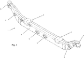
- Fig. 1 shows a three-dimensional view of an inventive Achs stressess 1 cast iron.
- the axle body 1 according to the invention is preferably used for motor vehicles.
- the axle body extends between the two wheel connections and is preferably formed as a one-piece cast iron part.
- the axle body 1 includes a cross-connection 2, which extends between two connection points 3 and spring supports 4.
- the connection points. 3 can be designed for steerable suspension parts as well as for non-steerable suspension parts, wherein in the Fig. 1-4 Pictured variant is formed with connection points 3 for steerable suspension parts.
- the cross-connection 2 which extends between the attachment points 3 is formed as a hollow body.
- Fig. 2 shows the inventive axle body 1 from above.
- the axle body 1 along the direction of travel of the motor vehicle is constructed mirror-symmetrically.
- the cross-connection 2 of the axle body 1 preferably has a cross-section on which the square is preferably formed as a rectangle.
- In 3 and 4 are sectional views showing the cross section of the cross-connection 2 at two different locations.
- Fig. 3 shows a sectional view in the region of a core opening 5
- Fig. 4 shows a sectional view in a region where no core opening 5 is arranged.
- the cross section of the cross-connection 5 can be seen which is preferably designed as a square as a rectangle.
- the wall thickness of the cross connection 2 is formed as constant as possible.
- the wall thickness or the dimension of the cavity of the transverse connection is designed such that the moment of resistance changes only slightly or scarcely in comparison to a transverse connection of solid material.
- the corners or edges that extend along the cross-connection are preferably rounded. This is also good in the 3 and 4 recognizable in which the outer corners are formed as a radius.
- the axle body 1 has core openings 5.
- the core openings 5 serve on the one hand to support the core in the casting mold and on the other hand to empty the core sand after the casting process.
- the core openings 5 are preferably formed round or as a slot as well as in Fig. 1 can be clearly seen, the core openings 5 may be formed differently both in size and shape.
- the axle body 1 preferably has at least three core openings 5.
- the core openings are arranged at least on two sides of the axle body 1, so that the core can be stable to that of the casting mold.
- the axle body 1 according to the invention is produced by the iron casting method in order to achieve the required strength values.
- the axle body 1 is preferably produced in the sand casting method in the green sand method.
Landscapes
- Engineering & Computer Science (AREA)
- Mechanical Engineering (AREA)
- Vehicle Body Suspensions (AREA)
- Springs (AREA)
Abstract
Description
- Die Erfindung betrifft einen Achskörper aus Eisenguss für Kraftfahrzeuge vorzugsweise Nutzfahrzeuge einer nicht angetriebenen Achse und das Verfahren zur Herstellung beinhaltend eine Querverbindung, Anbindungsstellen und Federauflagen.
- Solche Achskörper sind aus dem Stand der Technik bekannt. Meist sind sie als Schmiedeteil ausgebildet, wobei auch Achskörper bekannt sind die mittels Ziehprozess hergestellt wurden.
Aufgrund der hohen Belastungen, die auf den Achskörper durch die statischen Kräfte, die durch das Gewicht des Fahrzeugs und ebenso die dynamischen Kräfte speziell in extremen Fahr- und Bremssituationen entstehen, sind die Achskörper entsprechend massiv ausgelegt und weisen dementsprechend meist ein unerwünscht hohes Gewicht auf. - Um den Anforderungen der Biege- und Torsionsfestigkeit zu entsprechen werden oft Doppel-T-Profile eingesetzt, die durch ihren entsprechend dimensionierten Querschnitt aufgrund der auftretenden Belastungen ein hohes Gewicht aufweisen.
- Die
DE 10 2005 037 211 A1 offenbart einen Achskörper mit einem Doppel-T-Profil als Querschnitt und verstärkten Bereichen die hohen Belastungen unterliegen. - Nachteilig hierbei ist, dass durch die verstärkten Bereiche das Gewicht des Achskörpers erhöht wird.
- Die
DE 10 2009 020 099 A1 offenbart einen Achskörper der ein Doppel -T oder U-Profil als Querschnitt aufweist und zu dessen Gewichtsreduktion Ausnehmungen eingebracht sind. - Nachteilig hierbei ist der hohe Aufwand zur Herstellung des Achskörpers im Schmiedeverfahren.
- Aufgabe der Erfindung ist es einen Achskörper und ein damit verbundenes Verfahren zu dessen Herstellung vorzuschlagen, der den Belastungen stand hält und ein möglichst geringes Gewicht aufweist wie auch kostengünstig in der Herstellung ist.
- Die Aufgabe wird erfindungsgemäss dadurch gelöst, dass die Querverbindung des Achskörpers als Hohlkörper ausgebildet ist und der Achskörper im Eisengussverfahren hergestellt wird.
- Der Achskörper ist als einteiliges Eisengussstück ausgebildet und beinhaltet eine Querverbindung, die sich zwischen den Anbindungsstellen erstreckt. Die Anbindungsstellen dienen der beidseitigen Radanbindung, sie können zur Aufnahme von lenkbaren Aufhängungsteilen eines rechten und linken Rades vorzugsweisen Vorderrads ausgebildet sein wie auch für nicht lenkbare Aufhängungsteile bzw. Räder.
Die sich zwischen den Anbindungsstellen erstreckende Querverbindung ist als Hohlkörper ausgebildet. Der Hohlkörper weist als Querschnitt einen Vierkant vorzugsweise ein Rechteck auf. Die Ecken des Querschnitts und somit die Kanten, die sich entlang der Querverbindung erstrecken sind vorzugsweise abgerundet bzw. weisen einen Radius auf.
Durch die hohl ausgebildete Querverbindung ist der Querschnitt als hohler Vierkant bzw. hohles Rechteck ausgebildet wodurch ein hohes Widerstandsmoment gewährleistet ist. Zudem kann durch die hohle Ausgestaltung der Querverbindung trotz Material- und demzufolge Gewichtseinsparung ein Widerstandsmoment erreicht werden, das einem massiven Achskörper ohne Hohlraum entspricht. Mittels des erfindungsgemässen Achskörpers kann die geforderte Biege-und Torsionsfestigkeit mit geringem Gewicht erreicht wird. - An der Querverbindung sind vorzugsweise zwei Federauflagen angeordnet an denen bspw. Federn montiert werden können um den Achskörper federnd mit der Karosserie des Kraftfahrzeugs zur verbinden.
- Der Achskörper ist vorzugsweise symmetrisch in Bezug auf die Fahrtrichtung aufgebaut.
- Der Achskörper ist vorzugsweise als Vorderachse eines Kraftfahrzeugs ausgebildet.
- Die Querverbindung weist Kernöffnungen auf. Diese dienen einerseits der Abstützung des Kerns in der Gussform und andererseits der Entleerung des Kernsands nach dem Giessen des Achskörpers.
- Vorzugsweise sind die Kernöffnungen rund oder als Langloch ausgebildet wodurch keine Spannungsspitzen im Lastfall um die Kernöffnungen entstehen, sondern ein gleichmässiger Spannungsverlauf über den Achskörper erfolgt.
- Der Achskörper bzw. die Querverbindung weist mindestens drei Kernöffnungen auf. Als bevorzugte Ausgestaltung sind die Kernöffnungen auf mindestens zwei Seiten des Querverbinders angeordnet. Dies kommt daher, dass der Kern möglichst optimal in der Gussform abgestützt sein sollte.
- Der erfindungsgemässe Achsenkörper wird im Eisengiessverfahren hergestellt. Als bevorzugtes Eisengiessverfahren wird das Sandgussverfahren angewandt, speziell bevorzugt Grünsand.
- Ein Ausführungsbeispiel der Erfindung wird anhand der Figuren beschrieben, wobei sich die Erfindung nicht nur auf das Ausführungsbeispiel beschränkt. Es zeigen:
- Fig. 1
- eine dreidimensionale Ansicht eines erfindungsgemässen Achskörpers,
- Fig. 2
- eine Draufsicht eines erfindungsgemässen Achskörpers,
- Fig. 3
- eine Schnittansicht durch einen erfindungsgemässen Achskörper im Bereich von Kernöffnungen und
- Fig. 4
- eine Schnittansicht durch einen erfindungsgemässen Achskörper.
-
Fig. 1 zeigt eine dreidimensionale Ansicht eines erfindungsgemässen Achskörpers 1 aus Eisenguss. Der erfindungsgemässe Achskörper 1 wird für Kraftfahrzeuge vorzugsweise Nutzfahrzeuge eingesetzt. Der Achskörper erstreckt sich zwischen den beiden Radanbindungen und ist vorzugsweise als einteiliges Eisengussteil ausgebildet. Der Achskörper 1 beinhaltet eine Querverbindung 2, die sich zwischen zwei Anbindungsstellen 3 erstreckt und Federauflagen 4. Die Anbindungsstellen 3 können für lenkbare Aufhängungsteile wie auch für nicht lenkbare Aufhängungsteile ausgebildet sein, wobei die in denFig. 1-4 abgebildete Variante mit Anbindungsstellen 3 für lenkbare Aufhängungsteile ausgebildet ist.
Um Gewicht einzusparen aber dennoch der geforderten Festigkeit bzw. Biege- und Torsionsfestigkeit zu entsprechen ist die Querverbindung 2, die sich zwischen den Anbindungsstellen 3 erstreckt als Hohlkörper ausgebildet. Durch die hohle Ausgestaltung der Querverbindung 2 kann das Gewicht reduziert werden und das Widerstandsmoment der Querverbindung 2 bzw. des Achskörpers 1 dennoch im selben bzw. ähnlichen Umfang beibehalten werden.
Am Achskörper 1 angeordnet sind Federauflagen 4, welche zur Verbindung des Achskörpers 1 mit der Karosserie eines Kraftfahrzeugs dienen indem Federn oder Dämpferelemente an den Federauflagen 4 angebracht sind, die den Achskörper 1 federnd mit der Karosserie verbinden.
Fig. 2 zeigt den erfindungsgemässen Achskörper 1 von oben. Vorzugsweise ist der Achskörper 1 entlang der Fahrtrichtung des Kraftfahrzeugs spiegelsymmetrisch aufgebaut.
Die Querverbindung 2 des Achskörpers 1 weist vorzugsweise einen Querschnitt auf der als Vierkant vorzugsweises Rechteck ausgebildet ist. InFig. 3 und 4 sind Schnittansichten dargestellt, die den Querschnitt der Querverbindung 2 an zwei unterschiedlichen Stellen zeigen.Fig. 3 zeigt eine Schnittansicht im Bereich einer Kernöffnung 5 undFig. 4 zeigt eine Schnittansicht in einem Bereich wo keine Kernöffnung 5 angeordnet ist. InFig. 3 und 4 ist der Querschnitt der Querverbindung 5 ersichtlich der als Vierkant vorzugsweise als Rechteck ausgebildet ist. Die Wandstärke der Querverbindung 2 ist möglichst konstant ausgebildet. Die Wandstärke bzw. die Dimension des Hohlraums der Querverbindung ist derart ausgebildet, dass sich das Widerstandsmoment im Vergleich zu einer Querverbindung aus Vollmaterial nur geringfügig bzw. kaum verändert.
Die Ecken bzw. die Kanten, die sich entlang der Querverbindung erstrecken sind vorzugsweise abgerundet. Dies ist auch gut in denFig. 3 und 4 erkennbar in denen die äusseren Ecken als Radius ausgebildet sind.
Der Achskörper 1 weist Kernöffnungen 5 auf. Die Kernöffnungen 5 dienen einerseits der Abstützung des Kerns in der Gussform und andererseits der Entleerung des Kernsands nach dem Giessvorgang. - Die Kernöffnungen 5 sind vorzugsweise rund oder als Langloch ausgebildet wie auch in
Fig. 1 gut erkennbar ist können die Kernöffnungen 5 unterschiedlich ausgebildet sein sowohl in Grösse als auch Form. - Der Achskörper 1 weist vorzugsweise mindestens drei Kernöffnungen 5 auf. Die Kernöffnungen sind mindestens auf zwei Seiten des Achskörpers 1 angeordnet, so dass der Kern stabil der der Gussform liegen kann.
- Der erfindungsgemässe Achskörper 1 wir durch das Eisengussverfahren hergestellt um die benötigten Festigkeitswerte zu erreichen.
Vorzugsweise ist der Achskörper 1 im Sandgussverfahren speziell bevorzugt im Grünsandverfahren hergestellt. -
- 1
- Achskörper
- 2
- Querverbindung
- 3
- Anbindungsstelle
- 4
- Federauflage
- 5
- Kernöffnung
Claims (10)
- Achskörper (1) aus Eisenguss für Kraftfahrzeuge vorzugsweise Nutzfahrzeuge einer nicht angetriebenen Achse beinhaltend eine Querverbindung (2), Anbindungsstellen (3) und Federauflagen (4), dadurch gekennzeichnet, dass die Querverbindung (2) als Hohlkörper ausgebildet ist.
- Achskörper (1) nach Anspruch 1, dadurch gekennzeichnet, dass der Achskörper (1) als Vorderachse ausgebildet ist.
- Achskörper (1) nach einem der Ansprüche 1 oder 2, dadurch gekennzeichnet, dass der Querschnitt der Querverbindung (2) als Vierkant vorzugsweise Rechteck ausgebildet ist.
- Achskörper (1) nach einer der Ansprüche 1 bis 3, dadurch gekennzeichnet, dass in der Querverbindung (2) Kernöffnungen (5) angeordnet sind.
- Achskörper (1) nach einem der Ansprüche 1 bis 4, dadurch gekennzeichnet, dass die Kernöffnungen (5) rund oder als Langloch ausgebildet sind.
- Achskörper (1) nach einem der Ansprüche 1 bis 5, dadurch gekennzeichnet, dass mindestens drei Kernöffnungen (5) in der Querverbindung (2) angeordnet sind.
- Achskörper (1) nach Anspruch 6, dadurch gekennzeichnet, dass die Kernöffnungen (5) unterschiedliche Formen und Grössen aufweisen können.
- Achskörper (1) nach Anspruch 6 oder 7, dadurch gekennzeichnet, dass die Kernöffnungen (5) auf mindestens zwei Seiten des Querverbinders (2) angeordnet sind.
- Verfahren zur Herstellung eines Achskörpers (1) nach einem der Ansprüche 1 bis 8, dadurch gekennzeichnet, dass der Achskörper (1) im Eisengussverfahren hergestellt wird.
- Verfahren nach Anspruch 9, dadurch gekennzeichnet, dass der Achskörper (1) im Sandgussverfahren vorzugsweise Grünsand hergestellt wird.
Applications Claiming Priority (1)
| Application Number | Priority Date | Filing Date | Title |
|---|---|---|---|
| CH00172/16A CH712104A2 (de) | 2016-02-10 | 2016-02-10 | Achskörper aus Eisenguss für Kraftfahrzeuge. |
Publications (2)
| Publication Number | Publication Date |
|---|---|
| EP3208105A1 true EP3208105A1 (de) | 2017-08-23 |
| EP3208105B1 EP3208105B1 (de) | 2020-12-02 |
Family
ID=57984803
Family Applications (1)
| Application Number | Title | Priority Date | Filing Date |
|---|---|---|---|
| EP17154498.4A Active EP3208105B1 (de) | 2016-02-10 | 2017-02-03 | Achskörper |
Country Status (2)
| Country | Link |
|---|---|
| EP (1) | EP3208105B1 (de) |
| CH (1) | CH712104A2 (de) |
Families Citing this family (2)
| Publication number | Priority date | Publication date | Assignee | Title |
|---|---|---|---|---|
| US12208645B2 (en) | 2022-03-31 | 2025-01-28 | Caterpillar Inc. | Front axle for mining machines |
| US12269294B1 (en) | 2023-11-28 | 2025-04-08 | Arvinmeritor Technology, Llc | Axle beam |
Citations (5)
| Publication number | Priority date | Publication date | Assignee | Title |
|---|---|---|---|---|
| JPH07215004A (ja) * | 1994-02-04 | 1995-08-15 | Hitachi Metals Ltd | 強度および軽量化に優れた鋳造アクスルビーム |
| EP1440820A2 (de) * | 2003-01-27 | 2004-07-28 | ArvinMeritor Technology, LLC | Lenkbare Vorderachsträgervorrichtung |
| EP1749678A1 (de) * | 2005-08-06 | 2007-02-07 | MAN Nutzfahrzeuge Aktiengesellschaft | Achskörper für Nutzfahrzeugachsen |
| DE102007025684A1 (de) * | 2007-06-01 | 2008-04-30 | Daimler Ag | Lenkbare Achse für ein Kraftfahrzeug |
| DE102009020099A1 (de) | 2009-05-06 | 2009-12-24 | Daimler Ag | Achskörper für Kraftfahrzeuge |
-
2016
- 2016-02-10 CH CH00172/16A patent/CH712104A2/de not_active Application Discontinuation
-
2017
- 2017-02-03 EP EP17154498.4A patent/EP3208105B1/de active Active
Patent Citations (6)
| Publication number | Priority date | Publication date | Assignee | Title |
|---|---|---|---|---|
| JPH07215004A (ja) * | 1994-02-04 | 1995-08-15 | Hitachi Metals Ltd | 強度および軽量化に優れた鋳造アクスルビーム |
| EP1440820A2 (de) * | 2003-01-27 | 2004-07-28 | ArvinMeritor Technology, LLC | Lenkbare Vorderachsträgervorrichtung |
| EP1749678A1 (de) * | 2005-08-06 | 2007-02-07 | MAN Nutzfahrzeuge Aktiengesellschaft | Achskörper für Nutzfahrzeugachsen |
| DE102005037211A1 (de) | 2005-08-06 | 2007-02-08 | Man Nutzfahrzeuge Ag | Achskörper für Nutzfahrzeugachsen |
| DE102007025684A1 (de) * | 2007-06-01 | 2008-04-30 | Daimler Ag | Lenkbare Achse für ein Kraftfahrzeug |
| DE102009020099A1 (de) | 2009-05-06 | 2009-12-24 | Daimler Ag | Achskörper für Kraftfahrzeuge |
Also Published As
| Publication number | Publication date |
|---|---|
| CH712104A2 (de) | 2017-08-15 |
| EP3208105B1 (de) | 2020-12-02 |
Similar Documents
| Publication | Publication Date | Title |
|---|---|---|
| DE10140288C1 (de) | Querlenker | |
| EP2295827A2 (de) | Schwingungsdämpfer | |
| DE69903676T2 (de) | Rahmenanordnung | |
| DE102012103961A1 (de) | Achseinbindung für eine gefederte Fahrzeugachse | |
| EP3310594B1 (de) | Strebe für eine radaufhängung | |
| DE102016200609A1 (de) | Gerader Zweipunktlenker, insbesondere gerade Achsstrebe für ein Nutzfahrzeug | |
| DE102016223092A1 (de) | Fahrerhausstabilisator | |
| DE102020129504A1 (de) | Fahrgestellkonstruktion für ein Nutzfahrzeug | |
| WO2016001268A1 (de) | Traeger mit luftausgleichsbehälter | |
| EP3208105B1 (de) | Achskörper | |
| EP2810799B1 (de) | Verfahren zum Herstellen eines Fahrwerkslenkers und Fahrwerkslenker für ein Fahrzeug | |
| DE102009031289A1 (de) | Strebenkörper | |
| DE102014006205A1 (de) | Sitzquerträger für ein Kraftfahrzeug, Kraftfahrzeug-Rohbaustruktur mit einem Sitzquerträger, Verfahren zur Herstellung eines Sitzquerträgers, und Verfahren zur Herstellung einer Kraftfahrzeug-Rohbaustruktur | |
| DE102009016935A1 (de) | Querträger für Kraftfahrzeuge | |
| DE102019209008A1 (de) | Fahrzeugfelge für Fahrzeugluftreifen | |
| WO2024017957A1 (de) | Parksperrenrad | |
| DE102013016393A1 (de) | Mehrpunktlenker, insbesondere Vierpunktlenker, für Fahrzeuge | |
| DE102016207622A1 (de) | Verbundlenkerachse für ein Fahrzeug | |
| DE809012C (de) | Fahrzeugrahmen | |
| EP3712103B1 (de) | Satz von flurförderzeugen mit unterschiedlicher spurweite | |
| DE102009020099A1 (de) | Achskörper für Kraftfahrzeuge | |
| DE883568C (de) | Quertraeger fuer Fahrgestelle, insbesondere von Kraftfahrzeugen | |
| EP3461629A1 (de) | Faserverbundbauteil und verfahren zu dessen herstellung, sowie flügelstruktur | |
| DE102010020520A1 (de) | Lenker für eine Radaufhängung eines Kraftfahrzeugs | |
| DE102018133153A1 (de) | Fahrwerkseinrichtung für ein schienenfahrzeug |
Legal Events
| Date | Code | Title | Description |
|---|---|---|---|
| PUAI | Public reference made under article 153(3) epc to a published international application that has entered the european phase |
Free format text: ORIGINAL CODE: 0009012 |
|
| STAA | Information on the status of an ep patent application or granted ep patent |
Free format text: STATUS: THE APPLICATION HAS BEEN PUBLISHED |
|
| AK | Designated contracting states |
Kind code of ref document: A1 Designated state(s): AL AT BE BG CH CY CZ DE DK EE ES FI FR GB GR HR HU IE IS IT LI LT LU LV MC MK MT NL NO PL PT RO RS SE SI SK SM TR |
|
| AX | Request for extension of the european patent |
Extension state: BA ME |
|
| STAA | Information on the status of an ep patent application or granted ep patent |
Free format text: STATUS: REQUEST FOR EXAMINATION WAS MADE |
|
| 17P | Request for examination filed |
Effective date: 20180215 |
|
| RBV | Designated contracting states (corrected) |
Designated state(s): AL AT BE BG CH CY CZ DE DK EE ES FI FR GB GR HR HU IE IS IT LI LT LU LV MC MK MT NL NO PL PT RO RS SE SI SK SM TR |
|
| RAP1 | Party data changed (applicant data changed or rights of an application transferred) |
Owner name: GF CASTING SOLUTIONS LEIPZIG GMBH |
|
| RIC1 | Information provided on ipc code assigned before grant |
Ipc: B60B 35/00 20060101AFI20200629BHEP Ipc: B60B 35/02 20060101ALI20200629BHEP Ipc: B60B 35/08 20060101ALI20200629BHEP Ipc: B60B 35/06 20060101ALI20200629BHEP |
|
| GRAP | Despatch of communication of intention to grant a patent |
Free format text: ORIGINAL CODE: EPIDOSNIGR1 |
|
| STAA | Information on the status of an ep patent application or granted ep patent |
Free format text: STATUS: GRANT OF PATENT IS INTENDED |
|
| INTG | Intention to grant announced |
Effective date: 20200902 |
|
| GRAS | Grant fee paid |
Free format text: ORIGINAL CODE: EPIDOSNIGR3 |
|
| GRAA | (expected) grant |
Free format text: ORIGINAL CODE: 0009210 |
|
| STAA | Information on the status of an ep patent application or granted ep patent |
Free format text: STATUS: THE PATENT HAS BEEN GRANTED |
|
| AK | Designated contracting states |
Kind code of ref document: B1 Designated state(s): AL AT BE BG CH CY CZ DE DK EE ES FI FR GB GR HR HU IE IS IT LI LT LU LV MC MK MT NL NO PL PT RO RS SE SI SK SM TR |
|
| REG | Reference to a national code |
Ref country code: GB Ref legal event code: FG4D Free format text: NOT ENGLISH |
|
| REG | Reference to a national code |
Ref country code: AT Ref legal event code: REF Ref document number: 1340498 Country of ref document: AT Kind code of ref document: T Effective date: 20201215 Ref country code: CH Ref legal event code: EP |
|
| REG | Reference to a national code |
Ref country code: IE Ref legal event code: FG4D Free format text: LANGUAGE OF EP DOCUMENT: GERMAN |
|
| REG | Reference to a national code |
Ref country code: DE Ref legal event code: R096 Ref document number: 502017008420 Country of ref document: DE |
|
| PG25 | Lapsed in a contracting state [announced via postgrant information from national office to epo] |
Ref country code: NO Free format text: LAPSE BECAUSE OF FAILURE TO SUBMIT A TRANSLATION OF THE DESCRIPTION OR TO PAY THE FEE WITHIN THE PRESCRIBED TIME-LIMIT Effective date: 20210302 Ref country code: RS Free format text: LAPSE BECAUSE OF FAILURE TO SUBMIT A TRANSLATION OF THE DESCRIPTION OR TO PAY THE FEE WITHIN THE PRESCRIBED TIME-LIMIT Effective date: 20201202 Ref country code: FI Free format text: LAPSE BECAUSE OF FAILURE TO SUBMIT A TRANSLATION OF THE DESCRIPTION OR TO PAY THE FEE WITHIN THE PRESCRIBED TIME-LIMIT Effective date: 20201202 Ref country code: GR Free format text: LAPSE BECAUSE OF FAILURE TO SUBMIT A TRANSLATION OF THE DESCRIPTION OR TO PAY THE FEE WITHIN THE PRESCRIBED TIME-LIMIT Effective date: 20210303 |
|
| REG | Reference to a national code |
Ref country code: NL Ref legal event code: MP Effective date: 20201202 |
|
| PG25 | Lapsed in a contracting state [announced via postgrant information from national office to epo] |
Ref country code: SE Free format text: LAPSE BECAUSE OF FAILURE TO SUBMIT A TRANSLATION OF THE DESCRIPTION OR TO PAY THE FEE WITHIN THE PRESCRIBED TIME-LIMIT Effective date: 20201202 Ref country code: BG Free format text: LAPSE BECAUSE OF FAILURE TO SUBMIT A TRANSLATION OF THE DESCRIPTION OR TO PAY THE FEE WITHIN THE PRESCRIBED TIME-LIMIT Effective date: 20210302 Ref country code: LV Free format text: LAPSE BECAUSE OF FAILURE TO SUBMIT A TRANSLATION OF THE DESCRIPTION OR TO PAY THE FEE WITHIN THE PRESCRIBED TIME-LIMIT Effective date: 20201202 Ref country code: PL Free format text: LAPSE BECAUSE OF FAILURE TO SUBMIT A TRANSLATION OF THE DESCRIPTION OR TO PAY THE FEE WITHIN THE PRESCRIBED TIME-LIMIT Effective date: 20201202 |
|
| PG25 | Lapsed in a contracting state [announced via postgrant information from national office to epo] |
Ref country code: NL Free format text: LAPSE BECAUSE OF FAILURE TO SUBMIT A TRANSLATION OF THE DESCRIPTION OR TO PAY THE FEE WITHIN THE PRESCRIBED TIME-LIMIT Effective date: 20201202 Ref country code: HR Free format text: LAPSE BECAUSE OF FAILURE TO SUBMIT A TRANSLATION OF THE DESCRIPTION OR TO PAY THE FEE WITHIN THE PRESCRIBED TIME-LIMIT Effective date: 20201202 |
|
| REG | Reference to a national code |
Ref country code: LT Ref legal event code: MG9D |
|
| PG25 | Lapsed in a contracting state [announced via postgrant information from national office to epo] |
Ref country code: RO Free format text: LAPSE BECAUSE OF FAILURE TO SUBMIT A TRANSLATION OF THE DESCRIPTION OR TO PAY THE FEE WITHIN THE PRESCRIBED TIME-LIMIT Effective date: 20201202 Ref country code: SK Free format text: LAPSE BECAUSE OF FAILURE TO SUBMIT A TRANSLATION OF THE DESCRIPTION OR TO PAY THE FEE WITHIN THE PRESCRIBED TIME-LIMIT Effective date: 20201202 Ref country code: PT Free format text: LAPSE BECAUSE OF FAILURE TO SUBMIT A TRANSLATION OF THE DESCRIPTION OR TO PAY THE FEE WITHIN THE PRESCRIBED TIME-LIMIT Effective date: 20210405 Ref country code: CZ Free format text: LAPSE BECAUSE OF FAILURE TO SUBMIT A TRANSLATION OF THE DESCRIPTION OR TO PAY THE FEE WITHIN THE PRESCRIBED TIME-LIMIT Effective date: 20201202 Ref country code: EE Free format text: LAPSE BECAUSE OF FAILURE TO SUBMIT A TRANSLATION OF THE DESCRIPTION OR TO PAY THE FEE WITHIN THE PRESCRIBED TIME-LIMIT Effective date: 20201202 Ref country code: SM Free format text: LAPSE BECAUSE OF FAILURE TO SUBMIT A TRANSLATION OF THE DESCRIPTION OR TO PAY THE FEE WITHIN THE PRESCRIBED TIME-LIMIT Effective date: 20201202 Ref country code: LT Free format text: LAPSE BECAUSE OF FAILURE TO SUBMIT A TRANSLATION OF THE DESCRIPTION OR TO PAY THE FEE WITHIN THE PRESCRIBED TIME-LIMIT Effective date: 20201202 |
|
| REG | Reference to a national code |
Ref country code: DE Ref legal event code: R097 Ref document number: 502017008420 Country of ref document: DE |
|
| PG25 | Lapsed in a contracting state [announced via postgrant information from national office to epo] |
Ref country code: MC Free format text: LAPSE BECAUSE OF FAILURE TO SUBMIT A TRANSLATION OF THE DESCRIPTION OR TO PAY THE FEE WITHIN THE PRESCRIBED TIME-LIMIT Effective date: 20201202 Ref country code: IS Free format text: LAPSE BECAUSE OF FAILURE TO SUBMIT A TRANSLATION OF THE DESCRIPTION OR TO PAY THE FEE WITHIN THE PRESCRIBED TIME-LIMIT Effective date: 20210402 |
|
| PLBE | No opposition filed within time limit |
Free format text: ORIGINAL CODE: 0009261 |
|
| STAA | Information on the status of an ep patent application or granted ep patent |
Free format text: STATUS: NO OPPOSITION FILED WITHIN TIME LIMIT |
|
| REG | Reference to a national code |
Ref country code: BE Ref legal event code: MM Effective date: 20210228 |
|
| PG25 | Lapsed in a contracting state [announced via postgrant information from national office to epo] |
Ref country code: LI Free format text: LAPSE BECAUSE OF NON-PAYMENT OF DUE FEES Effective date: 20210228 Ref country code: IT Free format text: LAPSE BECAUSE OF FAILURE TO SUBMIT A TRANSLATION OF THE DESCRIPTION OR TO PAY THE FEE WITHIN THE PRESCRIBED TIME-LIMIT Effective date: 20201202 Ref country code: LU Free format text: LAPSE BECAUSE OF NON-PAYMENT OF DUE FEES Effective date: 20210203 Ref country code: CH Free format text: LAPSE BECAUSE OF NON-PAYMENT OF DUE FEES Effective date: 20210228 Ref country code: AL Free format text: LAPSE BECAUSE OF FAILURE TO SUBMIT A TRANSLATION OF THE DESCRIPTION OR TO PAY THE FEE WITHIN THE PRESCRIBED TIME-LIMIT Effective date: 20201202 |
|
| 26N | No opposition filed |
Effective date: 20210903 |
|
| GBPC | Gb: european patent ceased through non-payment of renewal fee |
Effective date: 20210302 |
|
| PG25 | Lapsed in a contracting state [announced via postgrant information from national office to epo] |
Ref country code: DK Free format text: LAPSE BECAUSE OF FAILURE TO SUBMIT A TRANSLATION OF THE DESCRIPTION OR TO PAY THE FEE WITHIN THE PRESCRIBED TIME-LIMIT Effective date: 20201202 Ref country code: SI Free format text: LAPSE BECAUSE OF FAILURE TO SUBMIT A TRANSLATION OF THE DESCRIPTION OR TO PAY THE FEE WITHIN THE PRESCRIBED TIME-LIMIT Effective date: 20201202 |
|
| PG25 | Lapsed in a contracting state [announced via postgrant information from national office to epo] |
Ref country code: ES Free format text: LAPSE BECAUSE OF FAILURE TO SUBMIT A TRANSLATION OF THE DESCRIPTION OR TO PAY THE FEE WITHIN THE PRESCRIBED TIME-LIMIT Effective date: 20201202 Ref country code: FR Free format text: LAPSE BECAUSE OF NON-PAYMENT OF DUE FEES Effective date: 20210228 Ref country code: GB Free format text: LAPSE BECAUSE OF NON-PAYMENT OF DUE FEES Effective date: 20210302 Ref country code: IE Free format text: LAPSE BECAUSE OF NON-PAYMENT OF DUE FEES Effective date: 20210203 |
|
| PG25 | Lapsed in a contracting state [announced via postgrant information from national office to epo] |
Ref country code: IS Free format text: LAPSE BECAUSE OF FAILURE TO SUBMIT A TRANSLATION OF THE DESCRIPTION OR TO PAY THE FEE WITHIN THE PRESCRIBED TIME-LIMIT Effective date: 20210402 |
|
| PG25 | Lapsed in a contracting state [announced via postgrant information from national office to epo] |
Ref country code: BE Free format text: LAPSE BECAUSE OF NON-PAYMENT OF DUE FEES Effective date: 20210228 |
|
| REG | Reference to a national code |
Ref country code: AT Ref legal event code: MM01 Ref document number: 1340498 Country of ref document: AT Kind code of ref document: T Effective date: 20220203 |
|
| PG25 | Lapsed in a contracting state [announced via postgrant information from national office to epo] |
Ref country code: AT Free format text: LAPSE BECAUSE OF NON-PAYMENT OF DUE FEES Effective date: 20220203 |
|
| PG25 | Lapsed in a contracting state [announced via postgrant information from national office to epo] |
Ref country code: HU Free format text: LAPSE BECAUSE OF FAILURE TO SUBMIT A TRANSLATION OF THE DESCRIPTION OR TO PAY THE FEE WITHIN THE PRESCRIBED TIME-LIMIT; INVALID AB INITIO Effective date: 20170203 |
|
| PG25 | Lapsed in a contracting state [announced via postgrant information from national office to epo] |
Ref country code: CY Free format text: LAPSE BECAUSE OF FAILURE TO SUBMIT A TRANSLATION OF THE DESCRIPTION OR TO PAY THE FEE WITHIN THE PRESCRIBED TIME-LIMIT Effective date: 20201202 |
|
| P01 | Opt-out of the competence of the unified patent court (upc) registered |
Effective date: 20230529 |
|
| PG25 | Lapsed in a contracting state [announced via postgrant information from national office to epo] |
Ref country code: MK Free format text: LAPSE BECAUSE OF FAILURE TO SUBMIT A TRANSLATION OF THE DESCRIPTION OR TO PAY THE FEE WITHIN THE PRESCRIBED TIME-LIMIT Effective date: 20201202 |
|
| PG25 | Lapsed in a contracting state [announced via postgrant information from national office to epo] |
Ref country code: TR Free format text: LAPSE BECAUSE OF FAILURE TO SUBMIT A TRANSLATION OF THE DESCRIPTION OR TO PAY THE FEE WITHIN THE PRESCRIBED TIME-LIMIT Effective date: 20201202 |
|
| PG25 | Lapsed in a contracting state [announced via postgrant information from national office to epo] |
Ref country code: MT Free format text: LAPSE BECAUSE OF FAILURE TO SUBMIT A TRANSLATION OF THE DESCRIPTION OR TO PAY THE FEE WITHIN THE PRESCRIBED TIME-LIMIT Effective date: 20201202 |
|
| PGFP | Annual fee paid to national office [announced via postgrant information from national office to epo] |
Ref country code: DE Payment date: 20250218 Year of fee payment: 9 |