EP3208120A1 - Dispositif de commande electronique et circuit de commande d'un systeme de suspension pneumatique d'un vehicule utilitaire - Google Patents
Dispositif de commande electronique et circuit de commande d'un systeme de suspension pneumatique d'un vehicule utilitaire Download PDFInfo
- Publication number
- EP3208120A1 EP3208120A1 EP16156357.2A EP16156357A EP3208120A1 EP 3208120 A1 EP3208120 A1 EP 3208120A1 EP 16156357 A EP16156357 A EP 16156357A EP 3208120 A1 EP3208120 A1 EP 3208120A1
- Authority
- EP
- European Patent Office
- Prior art keywords
- valve element
- control
- valve
- relative position
- counter
- Prior art date
- Legal status (The legal status is an assumption and is not a legal conclusion. Google has not performed a legal analysis and makes no representation as to the accuracy of the status listed.)
- Withdrawn
Links
- 239000000725 suspension Substances 0.000 title claims abstract description 16
- 230000008859 change Effects 0.000 claims abstract description 67
- 238000009423 ventilation Methods 0.000 claims description 28
- 230000002457 bidirectional effect Effects 0.000 claims description 10
- 238000012546 transfer Methods 0.000 claims description 8
- 230000001351 cycling effect Effects 0.000 claims description 7
- 230000003993 interaction Effects 0.000 claims description 6
- 230000005484 gravity Effects 0.000 claims description 4
- 230000008878 coupling Effects 0.000 description 43
- 238000010168 coupling process Methods 0.000 description 43
- 238000005859 coupling reaction Methods 0.000 description 43
- 230000007246 mechanism Effects 0.000 description 17
- 230000005540 biological transmission Effects 0.000 description 15
- 238000013022 venting Methods 0.000 description 13
- 230000006870 function Effects 0.000 description 9
- 230000000875 corresponding effect Effects 0.000 description 8
- 238000006073 displacement reaction Methods 0.000 description 8
- 210000003746 feather Anatomy 0.000 description 7
- 230000009471 action Effects 0.000 description 6
- 230000010355 oscillation Effects 0.000 description 6
- 230000000903 blocking effect Effects 0.000 description 5
- 230000002093 peripheral effect Effects 0.000 description 5
- 230000015572 biosynthetic process Effects 0.000 description 4
- 238000010276 construction Methods 0.000 description 4
- 230000001186 cumulative effect Effects 0.000 description 4
- 238000013461 design Methods 0.000 description 4
- 238000001514 detection method Methods 0.000 description 4
- 230000033228 biological regulation Effects 0.000 description 3
- 238000004891 communication Methods 0.000 description 3
- 230000001276 controlling effect Effects 0.000 description 3
- 238000012545 processing Methods 0.000 description 3
- 230000009467 reduction Effects 0.000 description 3
- 238000007789 sealing Methods 0.000 description 3
- 230000001133 acceleration Effects 0.000 description 2
- 230000004913 activation Effects 0.000 description 2
- 230000008901 benefit Effects 0.000 description 2
- 230000000740 bleeding effect Effects 0.000 description 2
- 238000012937 correction Methods 0.000 description 2
- 230000002596 correlated effect Effects 0.000 description 2
- 230000001419 dependent effect Effects 0.000 description 2
- 238000005553 drilling Methods 0.000 description 2
- 238000011156 evaluation Methods 0.000 description 2
- 238000009434 installation Methods 0.000 description 2
- 241001295925 Gegenes Species 0.000 description 1
- 241000209035 Ilex Species 0.000 description 1
- 230000003213 activating effect Effects 0.000 description 1
- 238000005273 aeration Methods 0.000 description 1
- 239000000872 buffer Substances 0.000 description 1
- 150000001875 compounds Chemical class 0.000 description 1
- 230000009849 deactivation Effects 0.000 description 1
- 238000011161 development Methods 0.000 description 1
- 230000018109 developmental process Effects 0.000 description 1
- 230000000694 effects Effects 0.000 description 1
- 230000008030 elimination Effects 0.000 description 1
- 238000003379 elimination reaction Methods 0.000 description 1
- 230000006698 induction Effects 0.000 description 1
- 230000010354 integration Effects 0.000 description 1
- 230000009347 mechanical transmission Effects 0.000 description 1
- 230000004044 response Effects 0.000 description 1
- 238000009420 retrofitting Methods 0.000 description 1
- 230000002441 reversible effect Effects 0.000 description 1
- 230000008054 signal transmission Effects 0.000 description 1
- 238000011144 upstream manufacturing Methods 0.000 description 1
Images













Classifications
-
- B—PERFORMING OPERATIONS; TRANSPORTING
- B60—VEHICLES IN GENERAL
- B60G—VEHICLE SUSPENSION ARRANGEMENTS
- B60G17/00—Resilient suspensions having means for adjusting the spring or vibration-damper characteristics, for regulating the distance between a supporting surface and a sprung part of vehicle or for locking suspension during use to meet varying vehicular or surface conditions, e.g. due to speed or load
- B60G17/015—Resilient suspensions having means for adjusting the spring or vibration-damper characteristics, for regulating the distance between a supporting surface and a sprung part of vehicle or for locking suspension during use to meet varying vehicular or surface conditions, e.g. due to speed or load the regulating means comprising electric or electronic elements
- B60G17/0152—Resilient suspensions having means for adjusting the spring or vibration-damper characteristics, for regulating the distance between a supporting surface and a sprung part of vehicle or for locking suspension during use to meet varying vehicular or surface conditions, e.g. due to speed or load the regulating means comprising electric or electronic elements characterised by the action on a particular type of suspension unit
- B60G17/0155—Resilient suspensions having means for adjusting the spring or vibration-damper characteristics, for regulating the distance between a supporting surface and a sprung part of vehicle or for locking suspension during use to meet varying vehicular or surface conditions, e.g. due to speed or load the regulating means comprising electric or electronic elements characterised by the action on a particular type of suspension unit pneumatic unit
-
- B—PERFORMING OPERATIONS; TRANSPORTING
- B60—VEHICLES IN GENERAL
- B60G—VEHICLE SUSPENSION ARRANGEMENTS
- B60G17/00—Resilient suspensions having means for adjusting the spring or vibration-damper characteristics, for regulating the distance between a supporting surface and a sprung part of vehicle or for locking suspension during use to meet varying vehicular or surface conditions, e.g. due to speed or load
- B60G17/02—Spring characteristics, e.g. mechanical springs and mechanical adjusting means
- B60G17/04—Spring characteristics, e.g. mechanical springs and mechanical adjusting means fluid spring characteristics
- B60G17/052—Pneumatic spring characteristics
- B60G17/0523—Regulating distributors or valves for pneumatic springs
- B60G17/0525—Height adjusting or levelling valves
-
- B—PERFORMING OPERATIONS; TRANSPORTING
- B60—VEHICLES IN GENERAL
- B60G—VEHICLE SUSPENSION ARRANGEMENTS
- B60G17/00—Resilient suspensions having means for adjusting the spring or vibration-damper characteristics, for regulating the distance between a supporting surface and a sprung part of vehicle or for locking suspension during use to meet varying vehicular or surface conditions, e.g. due to speed or load
- B60G17/02—Spring characteristics, e.g. mechanical springs and mechanical adjusting means
- B60G17/04—Spring characteristics, e.g. mechanical springs and mechanical adjusting means fluid spring characteristics
- B60G17/056—Regulating distributors or valves for hydropneumatic systems
- B60G17/0565—Height adjusting valves
-
- F—MECHANICAL ENGINEERING; LIGHTING; HEATING; WEAPONS; BLASTING
- F16—ENGINEERING ELEMENTS AND UNITS; GENERAL MEASURES FOR PRODUCING AND MAINTAINING EFFECTIVE FUNCTIONING OF MACHINES OR INSTALLATIONS; THERMAL INSULATION IN GENERAL
- F16K—VALVES; TAPS; COCKS; ACTUATING-FLOATS; DEVICES FOR VENTING OR AERATING
- F16K11/00—Multiple-way valves, e.g. mixing valves; Pipe fittings incorporating such valves
- F16K11/10—Multiple-way valves, e.g. mixing valves; Pipe fittings incorporating such valves with two or more closure members not moving as a unit
- F16K11/14—Multiple-way valves, e.g. mixing valves; Pipe fittings incorporating such valves with two or more closure members not moving as a unit operated by one actuating member, e.g. a handle
-
- F—MECHANICAL ENGINEERING; LIGHTING; HEATING; WEAPONS; BLASTING
- F16—ENGINEERING ELEMENTS AND UNITS; GENERAL MEASURES FOR PRODUCING AND MAINTAINING EFFECTIVE FUNCTIONING OF MACHINES OR INSTALLATIONS; THERMAL INSULATION IN GENERAL
- F16K—VALVES; TAPS; COCKS; ACTUATING-FLOATS; DEVICES FOR VENTING OR AERATING
- F16K31/00—Actuating devices; Operating means; Releasing devices
- F16K31/44—Mechanical actuating means
- F16K31/52—Mechanical actuating means with crank, eccentric, or cam
- F16K31/523—Mechanical actuating means with crank, eccentric, or cam comprising a sliding valve
-
- F—MECHANICAL ENGINEERING; LIGHTING; HEATING; WEAPONS; BLASTING
- F16—ENGINEERING ELEMENTS AND UNITS; GENERAL MEASURES FOR PRODUCING AND MAINTAINING EFFECTIVE FUNCTIONING OF MACHINES OR INSTALLATIONS; THERMAL INSULATION IN GENERAL
- F16K—VALVES; TAPS; COCKS; ACTUATING-FLOATS; DEVICES FOR VENTING OR AERATING
- F16K31/00—Actuating devices; Operating means; Releasing devices
- F16K31/44—Mechanical actuating means
- F16K31/53—Mechanical actuating means with toothed gearing
-
- B—PERFORMING OPERATIONS; TRANSPORTING
- B60—VEHICLES IN GENERAL
- B60G—VEHICLE SUSPENSION ARRANGEMENTS
- B60G2202/00—Indexing codes relating to the type of spring, damper or actuator
- B60G2202/40—Type of actuator
- B60G2202/42—Electric actuator
-
- B—PERFORMING OPERATIONS; TRANSPORTING
- B60—VEHICLES IN GENERAL
- B60G—VEHICLE SUSPENSION ARRANGEMENTS
- B60G2202/00—Indexing codes relating to the type of spring, damper or actuator
- B60G2202/40—Type of actuator
- B60G2202/442—Rotary actuator
-
- B—PERFORMING OPERATIONS; TRANSPORTING
- B60—VEHICLES IN GENERAL
- B60G—VEHICLE SUSPENSION ARRANGEMENTS
- B60G2204/00—Indexing codes related to suspensions per se or to auxiliary parts
- B60G2204/10—Mounting of suspension elements
- B60G2204/11—Mounting of sensors thereon
- B60G2204/116—Sensors coupled to the suspension arm
-
- B—PERFORMING OPERATIONS; TRANSPORTING
- B60—VEHICLES IN GENERAL
- B60G—VEHICLE SUSPENSION ARRANGEMENTS
- B60G2204/00—Indexing codes related to suspensions per se or to auxiliary parts
- B60G2204/40—Auxiliary suspension parts; Adjustment of suspensions
- B60G2204/419—Gears
- B60G2204/4191—Planetary or epicyclic gears
-
- B—PERFORMING OPERATIONS; TRANSPORTING
- B60—VEHICLES IN GENERAL
- B60G—VEHICLE SUSPENSION ARRANGEMENTS
- B60G2204/00—Indexing codes related to suspensions per se or to auxiliary parts
- B60G2204/40—Auxiliary suspension parts; Adjustment of suspensions
- B60G2204/419—Gears
- B60G2204/4193—Gears worm gears
-
- B—PERFORMING OPERATIONS; TRANSPORTING
- B60—VEHICLES IN GENERAL
- B60G—VEHICLE SUSPENSION ARRANGEMENTS
- B60G2400/00—Indexing codes relating to detected, measured or calculated conditions or factors
- B60G2400/05—Attitude
- B60G2400/051—Angle
- B60G2400/0516—Angular position of a suspension element
-
- B—PERFORMING OPERATIONS; TRANSPORTING
- B60—VEHICLES IN GENERAL
- B60G—VEHICLE SUSPENSION ARRANGEMENTS
- B60G2400/00—Indexing codes relating to detected, measured or calculated conditions or factors
- B60G2400/25—Stroke; Height; Displacement
- B60G2400/252—Stroke; Height; Displacement vertical
-
- B—PERFORMING OPERATIONS; TRANSPORTING
- B60—VEHICLES IN GENERAL
- B60G—VEHICLE SUSPENSION ARRANGEMENTS
- B60G2400/00—Indexing codes relating to detected, measured or calculated conditions or factors
- B60G2400/60—Load
- B60G2400/61—Load distribution
-
- B—PERFORMING OPERATIONS; TRANSPORTING
- B60—VEHICLES IN GENERAL
- B60G—VEHICLE SUSPENSION ARRANGEMENTS
- B60G2400/00—Indexing codes relating to detected, measured or calculated conditions or factors
- B60G2400/60—Load
- B60G2400/63—Location of the center of gravity
-
- B—PERFORMING OPERATIONS; TRANSPORTING
- B60—VEHICLES IN GENERAL
- B60G—VEHICLE SUSPENSION ARRANGEMENTS
- B60G2400/00—Indexing codes relating to detected, measured or calculated conditions or factors
- B60G2400/90—Other conditions or factors
- B60G2400/95—Position of vehicle body elements
-
- B—PERFORMING OPERATIONS; TRANSPORTING
- B60—VEHICLES IN GENERAL
- B60G—VEHICLE SUSPENSION ARRANGEMENTS
- B60G2500/00—Indexing codes relating to the regulated action or device
- B60G2500/20—Spring action or springs
- B60G2500/202—Height or leveling valve for air-springs
- B60G2500/2022—Height or leveling valve for air-springs with valve seat actuation for selectively adjusting neutral height
-
- B—PERFORMING OPERATIONS; TRANSPORTING
- B60—VEHICLES IN GENERAL
- B60G—VEHICLE SUSPENSION ARRANGEMENTS
- B60G2500/00—Indexing codes relating to the regulated action or device
- B60G2500/30—Height or ground clearance
-
- B—PERFORMING OPERATIONS; TRANSPORTING
- B60—VEHICLES IN GENERAL
- B60G—VEHICLE SUSPENSION ARRANGEMENTS
- B60G2600/00—Indexing codes relating to particular elements, systems or processes used on suspension systems or suspension control systems
- B60G2600/02—Retarders, delaying means, dead zones, threshold values, cut-off frequency, timer interruption
-
- B—PERFORMING OPERATIONS; TRANSPORTING
- B60—VEHICLES IN GENERAL
- B60G—VEHICLE SUSPENSION ARRANGEMENTS
- B60G2600/00—Indexing codes relating to particular elements, systems or processes used on suspension systems or suspension control systems
- B60G2600/07—Inhibiting means
-
- B—PERFORMING OPERATIONS; TRANSPORTING
- B60—VEHICLES IN GENERAL
- B60G—VEHICLE SUSPENSION ARRANGEMENTS
- B60G2600/00—Indexing codes relating to particular elements, systems or processes used on suspension systems or suspension control systems
- B60G2600/18—Automatic control means
- B60G2600/187—Digital Controller Details and Signal Treatment
- B60G2600/1877—Adaptive Control
-
- B—PERFORMING OPERATIONS; TRANSPORTING
- B60—VEHICLES IN GENERAL
- B60G—VEHICLE SUSPENSION ARRANGEMENTS
- B60G2600/00—Indexing codes relating to particular elements, systems or processes used on suspension systems or suspension control systems
- B60G2600/20—Manual control or setting means
-
- B—PERFORMING OPERATIONS; TRANSPORTING
- B60—VEHICLES IN GENERAL
- B60G—VEHICLE SUSPENSION ARRANGEMENTS
- B60G2800/00—Indexing codes relating to the type of movement or to the condition of the vehicle and to the end result to be achieved by the control action
- B60G2800/20—Stationary vehicle
- B60G2800/202—Stationary vehicle kneeling, e.g. for letting passengers on/off
-
- B—PERFORMING OPERATIONS; TRANSPORTING
- B60—VEHICLES IN GENERAL
- B60G—VEHICLE SUSPENSION ARRANGEMENTS
- B60G2800/00—Indexing codes relating to the type of movement or to the condition of the vehicle and to the end result to be achieved by the control action
- B60G2800/20—Stationary vehicle
- B60G2800/203—Stationary vehicle lowering the floor for loading/unloading
-
- B—PERFORMING OPERATIONS; TRANSPORTING
- B60—VEHICLES IN GENERAL
- B60G—VEHICLE SUSPENSION ARRANGEMENTS
- B60G2800/00—Indexing codes relating to the type of movement or to the condition of the vehicle and to the end result to be achieved by the control action
- B60G2800/90—System Controller type
- B60G2800/91—Suspension Control
- B60G2800/914—Height Control System
-
- B—PERFORMING OPERATIONS; TRANSPORTING
- B60—VEHICLES IN GENERAL
- B60G—VEHICLE SUSPENSION ARRANGEMENTS
- B60G2800/00—Indexing codes relating to the type of movement or to the condition of the vehicle and to the end result to be achieved by the control action
- B60G2800/90—System Controller type
- B60G2800/92—ABS - Brake Control
- B60G2800/922—EBV - Electronic brake force distribution
Definitions
- the invention relates to an electronic control device for an air suspension system of a commercial vehicle. Furthermore, the invention relates to a control circuit for an air suspension system of a commercial vehicle with an electronic control device. The invention also relates to a use of an electronic control device for a particular mechanically controlled level control valve device.
- electronic level control devices are known in which a level is detected by a sensor and electronically controlled by a control unit which compares the measured level height with a target value of a level height, valve devices which then bring about ventilation, venting or shutting off the air spring bellows to restore the predetermined level height.
- an arbitrarily manually brought about level change may be useful, for example.
- manually operated lifting-lowering valves are used, which are integrated in addition to a mechanical level control valve or an electronic level control device in the compressed air connection to the air spring bellows.
- US 7,878,065 B2 discloses a level control unit in which a pivotable arm is coupled to a vehicle axle. The pivoting of the arm is detected by a rotary sensor whose output signal is fed to a control unit.
- the control unit controls a servomotor, which moves a valve spool via a crank mechanism. Depending on the position of the valve slide, there is ventilation, ventilation or shut-off of an air spring bellows.
- the valve spool is acted upon in such a way that it assumes a blocking position without energizing the servomotor.
- US 2012/0146307 A1 discloses a mechanical level control valve in which the relative position of the housing relative to the vehicle frame is changeable.
- the change in the relative position of the housing of the mechanical level control valve relative to the vehicle frame in a pivoting of the housing while in a second variant, the housing is displaced translationally on the frame.
- the position changes of the housing of the mechanical level control valve for both variants result in a change of the reference level of the mechanical level control valve, for which then the mechanical level control takes place.
- the change of the reference level should be used for a level reduction to increase the driving stability at high speeds, to reduce the level to simplify loading and unloading of cargo or to simplify access to the cab.
- the change in the reference level can also be used to increase the level, for example, when driving over an uneven road or inclined roadway.
- the invention has for its object to propose an electronic control device for an air suspension system of a commercial vehicle, which allows the control of a mechanically operated level control valve device for a supplementary electronic influence of the level.
- the installation space requirements, the retrofitting of an existing air suspension system, the installation effort and the control options should be taken into account.
- the invention has for its object to propose a correspondingly improved control circuit for an air suspension system of a commercial vehicle with an electronic control device.
- the invention is also based on the object to propose a new use of an electronic control device with a control output for a mechanically controlled level control valve device.
- the particular level control valve device has a drive element which can be mechanically coupled to a vehicle wheel or a vehicle axle and which is moved in accordance with the current level.
- the drive element can be arranged directly on the vehicle wheel or the vehicle axle or with This example be coupled via a mechanical coupling mechanism.
- the drive element represents a current level of the vehicle wheel or the vehicle axle or an associated air spring bellows.
- the special level control valve device has a valve element. The valve element is mechanically coupled to the drive element, so that a movement of the valve element can be brought about by a movement of the drive element, that is to say by a change in the level.
- valve element cooperates with a counter-valve element.
- a valve may be formed with any number of ways and / or connections. If, for example, such a valve is designed as a slide valve, the valve element can form the valve slide, while the counter-valve element is formed by the bore or a sleeve in which the valve slide is displaceable for the different valve positions. However, if the valve is designed as a seat valve, the valve element may be formed by a valve stem, while the counter-valve element is formed by a valve seat.
- valve element and the counter-valve element may each be designed as a valve disc.
- a connection for an air spring bellows connected in a second relative position of the connection for an air spring bellows with a connection for ventilation and or in a third relative position, the connection for the air bag with a connection for a vent connected.
- a valve or cross-over cross section of the valve is formed between the valve element and the counter-valve element, which is shut off in the first relative position and is open in the second relative position and / or third relative position for producing the aforementioned compounds.
- the first relative position, the second relative position and the third relative position may be discrete positions or also position ranges, wherein in the latter case it is also possible for a position range depending on the position in the position range, the size of a cross section for aeration and / or or bleeding changes.
- the particular level control valve device is not exclusively mechanically actuated, that is, according to the deviation of the current level of a fixed reference level by mechanical change of the relative position of the valve element and the counter-valve element. Rather, in the particular level control valve device also an electronically controllable actuator is present. This may be, for example, an electronically controlled drive motor, possibly also with an associated gear or a coupling mechanism, or a pneumatic actuating cylinder which can be actuated by electronically controlled valves, or a pneumatic drive such as a vane motor or a reciprocating engine. By means of the actuator, the relative position of the valve element and the drive element can be changed.
- the relative position of at least one counter-valve element with respect to a housing, which accommodates the valve element and the counter-valve element is variable. Both alternatives result in that with the operation of the actuator, the relative position between the valve element and the counter-valve element can be changed.
- the commercial vehicle can also cumulative on the one hand movement of the valve element due to movement of the drive element and on the other hand, a change in the relative position between the valve element and the counter-valve element or between the counter-valve element and the housing brought about by electronic control of the actuator (including a regulation is understood).
- electronic control of the actuator including a regulation is understood.
- the electronically controllable actuator thus an alternative or cumulative mechanical and electronic actuation of the level control valve can be ensured, preferably for both types of actuation for ventilation and / or ventilation of the air spring bellows same valve components and the same formed between these valve components valve or Opening cross sections are used, whereby the construction cost can be significantly reduced.
- the actuator is integrated in the level control valve.
- the electronic control device generates at a control output thereof a suitable control signal for actuating the actuator of the particular level control valve device.
- the control device has control logic.
- the control logic generates at the control output a control signal for the actuator, which performs the electronic adjustment of the particular level control valve device.
- the control signal is generated by the control logic such that a change in a relative position of a valve element and drive element of the particular level control valve device is generated.
- the control signal may be generated by the control logic such that a relative position of a counter-valve element relative to a housing receiving the valve element and the counter-valve element is generated.
- control signal is generated for electronic control devices according to the prior art at a control output for an electronic level control, which controls a ventilation valve, vent valve and / or check valve and thus in particular binary switching signals On / Off, generated by the control logic at the control output Control signal for the operation of an actuator, which has a displacement or pivoting with in stages or continuously predefinable shift positions or pivot positions formed. If a reference position of the level control valve device to be changed, the control signal is determined by the control logic that this causes a displacement or pivoting on the actuator, which corresponds to the deviation of the changed desired reference position of the previously effective reference position.
- control logic no longer a control signal, which drives the actuator for generating a displacement or a pivoting.
- the control signal is proportional to the change in the reference position.
- the actuator to be designed with a stepping motor, whereby the control signal causes the number of steps to be brought about by the actuator, the number of steps correlating with the desired change in the reference position or the desired level change.
- such a control signal is not only used for a temporary change of a reference position of the particular level control valve device, but also for dynamic changes of the level and / or a shut-off of the level control valve device, for example in order to avoid a so-called cyclings.
- Another solution to the problem underlying the invention is the use of an electronic control device with a control output and a control logic for generating the previously explained control signal for the particular level control valve device.
- the control device has control logic which generates a control signal for the actuator when the operator manually changes the level, for example, a desire to raise or lower the vehicle body on a ramp, ie a desire for a change in the Reference levels.
- the control signal is determined by the control logic such that, based on the control signal, the actuator changes the relative position of the valve element and of the counter-valve element as desired by the operator. If the operator thus wishes to increase (or lower) the vehicle body by manual specification, the control signal is predefined by the control logic such that the relative position changes in the direction of the second relative position (or the third relative position).
- the function of a manual lifting / lowering valve can be integrated into the level control valve device without significant additional expenditure.
- additional valve elements need not be provided to ensure manual lifting and lowering. Rather, it is sufficient, a switch, lever u. ⁇ . Provide over which the operator can specify the desire for a lifting or lowering, which is then supplied to the control device and is further processed by the control logic.
- the control device has a control logic which generates a control signal for the actuator for a dynamic level control while driving.
- the actuator changes the relative position of the valve element and the counter-valve element such that a change in the relative position of the valve element and the counter-valve element results, the amount of which is greater than the amount of change in the relative position of the valve element and the counter-valve element.
- Valve element that would have resulted in purely mechanical level control.
- a ventilation cross-section is opened, but for the small level change is relatively small, so that the level adjustment would be relatively slow and with little dynamics.
- control signal can control the actuator so that it changes the relative position of the valve element and the counter-valve element so that there is a larger opening cross-section, which, in simple terms, can also simulate that a larger deviation of the actual level of Reference level.
- the enlargement of the valve cross section results in a faster, more dynamic level change. If the reference level is then reached again, the actuator can be reset by a control signal determined in accordance with the control logic.
- any superimposition of the electronic level control due to the interaction of the electronic control device with the control logic, the control signal and the actuator on the one hand and the purely mechanical level control on the other hand can be done with the electronic level control.
- the control logic of the control device for a dynamic level control while driving generates a control signal, based on which the actuator changes the relative position of the valve element and the counter-valve element so that the valve element and the counter-valve element remain in the first relative position or be converted into these, although they would be in purely mechanical level control in the second or third relative position.
- undesirable so-called "cycling" occurs during driving, in which oscillations of the vehicle body about a vehicle longitudinal or transverse axis lead to a successive ventilation of the air spring bellows mechanical level control, which is associated with an undesirable high compressed air consumption.
- Such cycling occurs, for example, as a result of oscillations about the roll axis when passing through a curve or oscillations about the pitch axis when the vehicle is decelerating at a traffic light.
- control logic in such operating situations, which can be determined on the basis of information already known, for example, via a bus system, the actuator for bringing about the first relative position control, whereby the bellows are shut off and the undesirable compressed air consumption does not occur.
- the control device has an input. About this input, the control device is supplied to a tilt signal for a trough or a vehicle body. A tilting of the trough or the vehicle body has a Displacement of the center of gravity result, which is undesirable under certain circumstances and in the worst case can lead to a tipping over of the commercial vehicle.
- the control logic of the control device generates a control signal at the control output for the mechanically controlled level control valve device. This control signal actuates the actuator to cause a change in the level that at least partially compensates for displacement of the center of gravity of the vehicle body or trough due to tilting of the trough or the vehicle body. As a result, the operational safety of the commercial vehicle can be increased.
- the electronic control device is equipped with a further function:
- the control device has control logic which generates at a control output a reset-to-ride control signal for a manually operated lift-lower switching valve. If the operator manually causes the lift / lower valve to move to a stable stop position or a latched or locked raise or lower position causes a manual change in level (eg on a ramp), the level control valve will be mechanically raised by the raise / lower valve Switch valve may be disabled. If the driving operation of the commercial vehicle is then recorded and the operator forgets the return of the lifting / lowering switching valve to the driving position, the mechanical level control which does not take place could lead to damage to the commercial vehicle and unstable driving conditions.
- the control logic of the control device recognizes for this embodiment of the invention the resumption of the driving operation (for example, based on a speed signal, the operation of a brake, a gear selector lever, the ignition, a brake light signal, and the like) and generates the reset-to-ride control signal, by means of which an unlocking of the raising or lowering position of the raising-lowering switching valve takes place and / or a provision of the raising-lowering switching valve in the driving position, in which the mechanical level control is activated, is brought about.
- the control device has at least one unidirectional connection.
- the electronic control device has (at least) one bi-directional connection.
- a bidirectional connection on the one hand by the control device, a signal with respect to the level of a level sensor of the level control valve device is received and on the other hand via the bidirectional connection, the control signal for controlling the actuator of the Level control valve device is transmitted.
- the control device has an interface for a bus system.
- lifting and / or lowering of the vehicle body may be caused by a manually operated lift-and-lower pilot valve, in which preferably mechanical-pneumatic valves are operated by the user.
- a mechanical-electrical operating element is provided, via which the operator can specify a change in a reference level and / or the desire to raise or lower the vehicle body and by means of which an electrical operating signal is generated, which correlated with the aforementioned desire of the operator.
- This electrical control signal is then used by the control device to control the actuator of the level control valve device with a control signal so that this implements the desire of the operator.
- control device itself as an integral structural unit having the mechanical-electrical control element. It is also possible that the mechanical-electrical operating element is formed externally by the control device, in which case the control device has a connection for receiving an electrical operating signal of the operating element.
- the control device has an electrical control output which can be connected to a valve or a control unit of a load transfer valve device.
- a load transfer valve device is used to control the action of bellows of different axes such that a predetermined axle load distribution, in particular an equal axle load, is set as far as possible on the axles.
- the control device can thus determine a control signal for the activation of the load transfer valve device.
- control circuit has a manually actuated mechanical-pneumatic raising-lowering switching valve, via which an operator can bring about a change in the level by mechanical actuation.
- control circuit has the previously described manually operable mechanical-electrical control element.
- predetermined electrical control signal is supplied to a control input of the electronic control device.
- At least one sensor is present.
- the sensor can detect a relative position of the drive element or drive pin and the actuating element or a position of the drive element, the drive pin and / or the actuating element.
- the control logic of the electronic control device determines the control signal for the actuator of the level control valve device on the basis of a signal of at least one sensor.
- any superimposition of the electronic level control due to the interaction of the electronic control device with the control logic, the control signal and the actuator on the one hand and the purely mechanical level control on the other hand can be done with the electronic level control.
- the control logic of the control device for dynamic level control during driving generates a control signal, based on which the actuator changes the relative position of the valve element and the counter-valve element so that the valve element and the counter-valve element remain in the first relative position or be converted into these, although they would be in purely mechanical level control in the second or third relative position.
- undesirable so-called "cycling" occurs during driving, in which oscillations of the vehicle body about a vehicle longitudinal or transverse axis lead to a successive ventilation of the air spring bellows mechanical level control, which is associated with an undesirable high compressed air consumption.
- Such cycling occurs, for example, as a result of oscillations about the roll axis when passing through a curve or oscillations about the pitch axis when the vehicle is decelerating at a traffic light.
- control logic in such operating situations, which on the basis of anyway, for example, via a bus system known information can be detected, the actuator to bring about the first relative position control, whereby the air spring bellows are shut off and the undesirable compressed air consumption does not occur.
- the invention proposes that the control logic of the electronic control device generates a control signal for the actuator for detection of an imminent boarding or disembarking of passengers. Based on the control signal, the actuator changes the relative position of the valve element and the counter-valve element so that there is a reduced ride height, which facilitates boarding or disembarking.
- Detection of (imminent) boarding or alighting may be effected on the basis of a signal manually given by the driver or actuation of a switch by a passenger in the vehicle to indicate that he wishes to get off, or by a person outside the vehicle who is in want to get in the vehicle.
- the control logic generates a control signal for the actuator. Based on this control signal then the actuator changes the relative position of the valve element and the counter-valve element so that there is a predefined ride height.
- the detection preferably takes place by evaluation of a signal predetermined by the driver.
- Fig. 1 shows highly schematic in a section of a commercial vehicle, the support of a vehicle wheel 1 or a vehicle axle 2 via an air spring bellows 3 on a vehicle frame 4 or vehicle body.
- a ventilation of the air spring bellows 3 the change of a level 5, which describes the distance of the axis of rotation of the vehicle wheel 1 or the vehicle axle 2 of the vehicle frame 4, can be changed.
- the Ventilation or venting can be done here, for example, to compensate for dynamic level changes due to acceleration, deceleration when cornering on uneven roads or targeted a level change, eg. Manually by a user for raising the vehicle frame 4 to the height of a ramp or to change level 5 when driving on a highway or depending on road bumps.
- This is designed as a singular unit, which may be modular under some circumstances, and has a housing 7, with which the level control valve 6 attached to the vehicle frame 4 and is fixed.
- the level control valve 6 has pneumatic connections, here a connection 8 for connection to a compressed air source, a connection 9 for connection to the air spring bellows 3 and a connection 10 for connection to another, different vehicle axle or other vehicle associated air spring bellows (here not shown).
- the level control valve 6 has a rotatable drive shaft 11, wherein via the rotation of the drive shaft 11, the ventilation and the shut-off of the air spring bellows 3 is mechanically controlled.
- the drive shaft 11 is mechanically coupled via a mechanical coupling mechanism 12 to a drive element 13, which is supported by the vehicle axle 2 or the vehicle wheel 1 and is moved vertically with the level change, without turning with the rotation of the vehicle wheel 1.
- the drive element 13 is designed as a drive strut 14, which is articulated in an end region on the vehicle axle 2 or the vehicle wheel 1.
- the coupling mechanism 12 has two coupling rods 15, 16, which are pivotally connected to each other via a hinge 17.
- the coupling rod 15 is fixed in the end region facing away from the hinge 17 on the drive shaft 11, so that the pivoting of the coupling rod 15 corresponds to the pivoting of the drive shaft 11.
- the coupling rod 16 is articulated in the end region remote from the joint 17 via a joint 18 on the drive strut 14. A change in the level 5 leads to a change in the angle between the drive strut 14, the coupling rod 15 and the coupling rod 16 and thus to a rotation of the drive shaft eleventh
- the coupling rod 16 has two coupling rod parts 19, 20.
- the coupling rod parts 19, 20 are connected to each other via an actuator 21.
- the actuator 21 is electronically controlled to change its length, whereby the distance between the coupling rod parts 19, 20 changed and the length of the coupling rod 16 changes.
- a rotation of the drive shaft 11 can be brought about, whereby electronically a ventilation or shut-off of the air spring bellows 3 can be brought about and a change of a reference level can take place.
- any actuator for generating a longitudinal travel can be used.
- the actuator 21 may be formed as a pneumatic cylinder acting simply against a spring or as a double-acting pneumatic cylinder whose travel is controlled by the electronic control of at least one solenoid valve. It is also possible that here a spindle drive, a servo motor with screw gear or a stepper motor for generating a travel in the longitudinal direction can be used, to name just a few non-limiting examples. Deviating from Fig. 1 Alternatively or cumulatively, an actuator 21 for effecting a change in the length of the coupling rod 15 can also be integrated into the coupling rod 15. A transmission of a pneumatic and / or electrical signal for controlling the actuator 21 can take place via a free line or by an integrated into the coupling mechanism 12 or attached to this line.
- the level control valve device 22 is formed with the level control valve 6, the mechanical coupling mechanism 12 and the actuator 21 integrated therein.
- the level control valve 6 may basically be formed according to a conventional level control valve.
- the level control valve device 22 allows both the mechanical control via the mechanical coupling with the vehicle wheel 1 or the vehicle axle 2, the level control valve 6 preferably has no electronic components, no electronic control port and no control unit. Rather, here the electronically controlled components are integrated into the mechanical coupling mechanism 12.
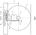
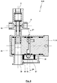
- Fig. 3 to 13 show embodiments in which the level control valve device 22, which allows both the mechanical level control depending on level 5 and the electronic level control, is formed by the level control valve 6.
- the drive shaft 11 of the level control valve 6 forms the drive element 13, the relative position relative to the valve element 23 to be controlled electronically.
- the level control valve 6 is designed in construction as a slide valve.
- an actuating element 24 is rotatably mounted in the housing 7 of the level control valve 6, in which an actuating element 24 is rotatably mounted.
- This has an eccentric or cam 25, to which via a spring 26, the valve element 23, here a valve spool 27, is pressed.
- the eccentric 25 pushes the valve element 23 in the longitudinal direction of a bore 28 of the housing 7, which forms a counter-valve element 29.
- the in Fig. 3 illustrated operating position closes a control edge 30, the mouths 31, 32 of the terminals 9, 10 in the bore 28, in which case a throttle is present between the mouth 31, 32 and the terminals 9, 10 respectively.
- valve element 23 If the valve element 23 from the position according to Fig. 3 moved upward, a second relative position is reached, in which for the ventilation of the air spring bellows 3, the terminals 9, 10 are connected to the terminal 8.
- the valve element 23 In the second relative position, the valve element 23 is formed with the jointly moved valve spool 27 and the valve disk 36.
- the ventilating crossover cross section is then formed between the valve element 23 with the valve disk 36 and the counter-valve element 29, here the valve seat 35.
- the cross-over cross-section increases with increasing movement of the valve member 23 upwards.
- the third relative position in which the ports 9, 10 are vented for the air spring bellows 3, achieved when the valve element 23 has moved away with the control edge 30 of the mouths 31, 32 down and also the end face of the valve element 23rd , here the valve spool 27, has moved away from the valve disk 36, which is an immovable component of the counter-valve element 29.
- the venting inner bore 37 is connected in a manner not shown to terminal 39 for venting.
- the venting cross section increases between the end face of the Valve element 23 and the valve plate 36 with increasing movement of the valve element 23 down.
- the actuator 24 may be rotatably or integrally formed with the drive shaft 11.
- the electronic level control by changing the relative angle of rotation between the drive shaft 11, on which the coupling mechanism 12 is articulated, and the actuating element 24.
- the actuating element 24 and the drive shaft 11 about a common axis of rotation 40 are rotatable.
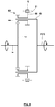
- a planetary gear 41 is interposed, the structure in Fig. 5 is shown schematically.
- the planetary gear 41 has a sun gear 42 which is mounted with a sun gear 43 in bearings 44, 45 rotatably mounted in the drive shaft 11 and the actuator 24.
- the sun gear 42 is equipped as a double sun gear with two Sonnenradvertechnikept with the same diameter, which mesh with arranged in parallel planes planetary gears 46, 47.
- a web 48 supporting the planetary gear 46 is rotated with the drive shaft 11. Accordingly, a planetary gear 47 overlapping web 49 is rotated with the actuator 24.
- the planetary gear 47 meshes radially outboard with a ring fixed to the housing 50, while the planetary gear 46 meshes with a ring gear 51, which is rotatable via a drive unit 54.
- the ring gear 51 has external teeth 52, for example.
- a worm toothing via which the ring gear 51 of a drive shaft 53, here a worm shaft, from the drive unit 54, here an electric motor, can be driven in both directions of rotation.
- Fig. 3 are integrated in the level control valve 6 sensors 55, 56, which are designed here as Hall sensors.
- the sensor 55 detects the angle of rotation of the drive element 13, while the sensor 56 detects the angle of rotation of the actuating element 24.
- the drive element 13 and the actuating element 24 in the region of their lateral surface have a permanent magnet which, as shown, is guided closely adjacent to the receiver of the sensor 55, 56.
- the sensors 55, 56 are connected to a board 57 or even carried by this, which is preferably responsible for the control of the drive unit 54 and the evaluation of the signals of the sensors 55, 56.
- the level control valve 6 also has an electrical connection, in particular for a connection to a data bus, the connection to further control units and / or an electrical power supply.
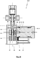
- Fig. 6 and 7 show a level control valve 6, wherein (in otherwise Fig. 3 to 6 appropriate design) between the drive member 13 and the actuator 24, another planetary gear 41 is interposed, which in Fig. 8 is shown schematically:
- a two planetary gears 58, 59 trained double planet 60 is rotatably mounted.
- the planetary gear 58 meshes here exclusively radially outboard with the ring gear 51, which has the teeth 52 and is driven by the drive unit 54.
- the planetary gear 59 meshes only radially inwardly with the sun gear 42, which is rotatably connected in this case with the actuator 24.
- the ratio between the drive member 13 and the actuator 24 can be selected, wherein it is also possible that the drive member 13 and the actuator 24 rotate by the same angle. Again, by adjusting the actuator 21, an adjustment of the reference level done.
- Fig. 9 schematically shows another in a level control valve 6 between a drive element 13 and an actuator 24 can be used planetary gear 41.
- the drive element 13 drives directly the sun gear 42 at.
- the actuator 24 is fixed with the ring gear 50 is connected.
- the only planetary gear 46 (or a corresponding planetary gear) meshes radially outboard with the ring gear 50 and radially inwardly with the sun gear 42.
- the planetary gear 46 overlapping web 48 is held without electronic control of the drive unit 54, while this with electronic control and Drive the drive unit 54 can be rotated.
- Fig. 10 shows a modified embodiment of the level control valve 6, in which the rotation of the drive shaft 11 is converted via a drive connection 61 in a translational movement of an actuating element 24.
- the drive connection 61 has an eccentric 62 which is rotated with the drive shaft 11.
- the eccentric 62 engages in a recess or groove 63 of the actuating element 24, whereby the rotation of the eccentric 62 can cause the translatory movement of the actuating element 24.
- the actuator 21 acts between the actuating element 24 and the valve element 23.
- the actuator 21 in this case generates a longitudinal displacement or "extension and retraction" of the valve element 23 from the actuator 24.
- the actuator is driven here by means of a drive unit 54 Spindle drive, axial stepper o.
- a friction element 67 is integrated, which increases the friction in the power flow between the drive element 13, actuator 21 and valve element 23 such that an undesirable adjustment of the same valve element 23 for a once brought about position even without energization of the drive unit 54 due a self-locking does not take place.
- the actuator 24 has an outgoing from the longitudinal bore for receiving the valve member 23 blind hole 68, at the bottom of a Federfußyak a spring 69 is supported.
- the spring 69 is biased and pushes with its other spring base a friction body 70, for example. Rubber, against the lateral surface of the valve element 23 in order to increase the friction.
- Fig. 12 and 13 show a level control valve 6 in disc design.
- the level control valve 6 has three valve disks 71, 72, 73.
- the valve disks 71, 72, 73 are inserted in this order into a bore 74 of the housing 7.
- the valve disks 71, 72, 73 are pressed against each other (except for the desired crossover cross sections and channels) against the bottom of the bore 74 by a spring 75, for which purpose sealing elements, not shown here, can act between the valve disks 71, 72, 73.
- the valve disc 71 is stationary and non-rotatable disposed in the housing 7, provides transmission channels 76, 77, here in the form of stepped staggered through holes of the valve discs 71, for connection to the terminals 8, 39 available.
- the middle valve disk 72 can be rotated via the actuator 21.
- the actuator 21 as in the previous embodiments, with a drive shaft 53, in particular a worm shaft, and a drive unit 54 is formed, wherein the drive shaft 53 meshes with an external toothing of the valve disc 72.
- On the valve disc 71 side facing the valve disc 72 has circumferentially continuous peripheral channels 78, 79, which are formed as circumferential grooves and in which the transmission channels 76, 77 open as shown. According to Fig.
- the valve disc 72 has through elongated holes 80, 81, 82, which extend with different extension in a partial circumference and are arranged concentrically to one another.
- the slot 80 extends approximately from a 01:30 clock position to a 02:45 clock position.
- the slot 81 extends from a 1:30 o'clock position to a 4:15 o'clock position.
- the slot 82 extends from a 3:15 clock position to a 4:15 clock position.
- the slot 81 is independent of the angle of rotation of the valve disks 71, 72, 73 permanently connected to the terminal 9 for the air spring bellows 3 in pneumatic communication, which can be done through suitable channels and grooves of the valve disc 71 therethrough.
- the slot 80 is connected via the peripheral channel 79 in permanent communication with the terminal 8, while the slot 82 via the peripheral channel 78 is permanently in pneumatic communication with the terminal 39.
- the valve disk 73 On the side facing the valve disk 72, the valve disk 73 has a transmission channel 83 designed as a radial groove.
- the black lines in FIG Fig. 12 is in Fig. 12 the transmission channel 83 is shown schematically for different rotational angles of the valve disc 73.
- this first relative position 84 between the valve discs 72, 73 of the transmission channel 83 is pneumatically connected to the slot 81, but not with the elongated holes 80, 82. In this way, the connection 9 for the air bag 3 over the Contact between the valve discs 72, 73 shut off.
- the valve disc 73 is rotationally fixed, here via a square 85, but axially displaceably connected to the drive element 13 or the drive shaft 11.
- a reduction of the level 5 leads to the pivoting of the valve disc 73 via the drive element 13 in the counterclockwise direction in the direction of the second relative position 86 (see. Fig. 12 ).
- the transmission channel 83 connects the long holes 80, 81 with each other, while no connection to the long hole 82 exists.
- this second relative position 86 there is thus a connection of the connection 9 to the connection 8, so that ventilation of the air spring bellows 3 can take place.
- an increase in the level 5 leads to a pivoting of the valve disc 73 in the clockwise direction in the direction of the third relative position 87.
- a conventional mechanical level control in particular via a mechanical coupling mechanism 12, can thus take place by means of the level control valve 6.
- a reference level can be additionally adjusted by rotation of the valve disc 72 by means of the actuator 21 and / or a dynamic level control by an electronic control. It is possible that, as in Fig. 12 shown, further elongated holes corresponding to the slots 80, 81, 82 are provided on the valve disc 72 and a further transmission channel 83 on the valve disc 73, to allow a level control for a two-circuit air suspension system.
- the level control valve 6 is designed as a slide valve (see. Fig. 3 )
- the mechanical level control via the movement of the valve element 23 are brought about, while the counter-valve element 29 is not formed in this case of the housing 7, but rather by a relative to the housing slidably mounted sleeve, which can then form control edges or crossover cross sections limited and which can be moved via the actuator 21 for electronic level control.
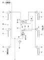
- Fig. 14 shows the integration of a level control valve device 22, in particular a level control valve 6, in an electropneumatic control circuit 88 for an air suspension system of a commercial vehicle.
- the coupling mechanism 12 is shown only schematically.
- the connection 9 is here connected to air suspension bellows 3 a, 3 b, 3 c of the right side of the vehicle connected in series with said air spring bellows 3 a, 3 b, 3 c, while the connection 10 is connected correspondingly to air suspension bellows 3 d, 3 e, 3 f of the left side of the vehicle.
- the port 8 is supplied from a reservoir 89 with compressed air.
- the bellows 3a-3f are each associated with a vehicle wheel 1 a-1 f or the vehicle wheels 1 a-1 f associated vehicle axles.
- the level control valve device 22 or the level control valve 6 has an electrical connection 90. Connected to the connection 90 here is a control line 91, via which the level control valve device 22 is sent a control signal for actuating the actuator 21.
- the control signal is generated by an electronic control device 92, which has a control output 93, to which the control line 91 is connected and via which the control signal is transmitted to the level control valve device 22.
- the electronic control device 92 may be an ABS or EBS control unit, without this necessarily being the case.
- the electronic control device 92 may be formed as an integral singular unit, as a modular unit or as a distributed unit with a plurality of sub-control units.
- the control device 92 furthermore has an input connection 94, via which the control device 92 is supplied with a level signal.
- This level signal originates from a conventionally designed level control valve 95, which, for example, is assigned to one of the three axes and into which a level sensor can be integrated.
- the input port 94 may be connected to any other level sensor which detects the level of the vehicle axle and / or the vehicle wheel on any vehicle axle.
- Via a further control input 96 or an interface 97 the control device 92 is connected to a control element 98.
- the operator 98 may manually and arbitrarily cause a level change or predefine a reference level, cause a predetermined ramp level, or cause a rise or fall.
- the operating element 98 can be configured as desired, provided that an electrical signal can be generated here, which transmits the respective request of the operator to the control device 92.
- Just a few non-limiting examples can call the control element 98 at least one switch, at least one pivotable lever, at least one translationally movable control element o. ⁇ .
- the operation correlates with the desire of the operator and generates a corresponding input signal for the control device 92. It is possible, for example, also that the operating element 98 according to the document WO 2014/124944 A1 is formed and operated, this document is made the subject of the present patent application.
- the operator can influence the level 5 or change a reference level via the operating element 98.
- the controller 92 converts the signals given by the operator to the control element 98 in a suitable control of the actuator 21. If, for example, via the control element 98 at a ramp a desired reference level corresponding to the height of the ramp given, can also in case of elimination of the electric power supply a mechanical level control carried out loading or unloading via the mechanical coupling mechanism 12, in which the changed reference level predetermined via the operating element 98 is maintained.
- the signal of a sensor integrated into the level control valve device 22, in particular a sensor 55, 56, is used by the control device 92.
- the level control valve device 22 in this case has an output 99 for the signal of the sensor, which is then supplied via a signal line 100 to the input terminal 94 of the control device 92.
- the bellows 3d, 3e, 3f a vehicle side via a pressure signal line 101 to a pneumatic port 102 of the controller 92 are connected.
- a pressure sensor may then be present, which detects the pressure at the port 102, which then in the control device 92, the pressure in the air spring bellows 3d, 3e, 3f known and can be used for a control or regulation.
- the control device 92 may have a connection 103 to which the reservoir 89 is connected. Via a pressure sensor integrated in the control device 92, the pressure in the reservoir 89 can then also be detected and taken into account by the control or regulation of the control device 92.
- the operating element 98 communicates via a bus system 104 with the interface 97 of the control device 92, wherein via the bus system 104 then other operating variables such as, for example, a steering angle, a vehicle speed, a gear, a geodetic location, etc. can be transmitted to the control device 92. It is also possible that the control device 92 operating variables, for example. A pressure in an air spring bellows and / or the reservoir, a level 5 u. ⁇ ., About the bus system 104 transmits to other control devices.
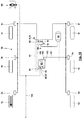
- Fig. 16 shows an embodiment in which the level control valve device 22 via a conventional raising-lowering switching valve 105, such as this example.
- a conventional raising-lowering switching valve 105 such as this example. Is sold by the company Haldex Brake Products GmbH under the name “COLAS” or by the competitor WABCO GmbH under the label “TASC” , is connected to the air bellows 3a-3f of the two sides of the vehicle. While it is basically possible for such a raising / lowering switching valve 105 to be disposed upstream of the level control valve device 22 between the reservoir 89 and the level control valve device 22, the raising / lowering switching valve 105 is disposed downstream of the level control valve device 22. In addition to the possibility of level 5 according to Fig.
- the control device 92 generates in this case, a so-called reset-to-ride signal in the event that from a vehicle speed sensor, the engagement of a gear, the operation of a brake pedal, the operation of a brake light switch u. ⁇ . Is recognized that a driving operation is recorded.
- This reset-to-ride signal is transmitted via the control output 106 of the valve device 92 to the control input 107 of the raising-lowering switching valve 105, which then the lifting-lowering switching valve 105 is transferred from a position lifting, lowering and / or stop in a position driving, in which the level control via the level control valve device 22 takes place, even if the user has forgotten, the lifting-lowering switching valve 105 by manual operation of the same back to the driving position convict.
- a bidirectional line 108 is used, which is connected via bidirectional connections 109, 110 in one end region with the control device 92 and the other end region with the level control valve device 22.
- a level signal from the level control valve device 22 to the control device 92 of the level control valve device 22 can be transmitted to the control device 92 via the bidirectional line 108 and, on the other hand, the control signal can be transmitted from the control device 92 to the level control valve device 22 for actuating the actuator 21 via the bidirectional line 108 become.
- Fig. 18 shows an embodiment in which the control element 92 itself is designed as an electronic control device 92 and has a control output 93, via which the transmission of a control signal to the terminal 90 of the level control valve device 22 takes place. Again, it is possible that in the reverse direction, for example. Via a bidirectional line, a signal with respect to a level 5 of the level control valve device 22 from this to the controller 92 and the control element 98 is transmitted to further processing in the controller 92. On the other hand, a Signal level 5 via an output 111 of the level control valve device 22 to another control unit, here an EBS control unit 112, transmitted for further processing.
- EBS control unit 112 another control unit
- the EBS control unit 112 is not responsible for the electronic control of the level control valve device 22, but rather exclusively for the control of the brakes. It is possible here, also a transmission of signals between individual components via a bus system, so for example. Between the control element 98 and the level control valve device 22 and / or the level control valve device 22 and the EBS control unit 112. Also in this embodiment, a conventional lifting and lowering Switching valve 105 optionally be additionally integrated into the control circuit 88.
- control element 98 transmits only a switching signal to a control unit or board of the level control valve device 22, in which case the signals of the control element 98 could be fed directly to the control unit of the level control valve device 22.
- the processing of the signals then takes place on the control unit or board of the level control valve device 22 (the same applies to the other preceding figures).
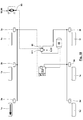
- Fig. 19 shows an embodiment in which an additional electronic control unit 113 is present, which specifies a pneumatic pressure for a so-called load-transfer valve device 114.
- the load-transfer valve device 114 has solenoid valves 115, 116, which are also controlled by the EBS control unit 112.
- the control via the EBS control unit 112 as well as the control unit 113 takes place here with the aim that the different axes of the vehicle are subjected to the same load.
- the EBS control unit 112 is also responsible for the control of a Liftachssystems 117.
- Fig. 21 shows an embodiment of the control circuit 88, in which a first control device 92, a level control valve means 6, 22 controls, in which both an electronic level control and a mechanical level control is possible.
- the level control valve device 22 is responsible in this case for a dual-circuit level control of the air spring bellows 3a, 3b and 3d, 3e of two vehicle axles.
- a further control device 113 controls purely electronically a further level control valve 118, via which the level control of the air spring bellows 3c, 3f takes place.
- control devices 92, 113 communicate with each other, whereby an adjustment or tuning of the levels on the one hand of the bellows 3a, 3b and 3d, 3e and on the other hand of the air spring bellows 3c, 3f can be done.
- the manual request can be predetermined by the user via the operating element 98, with which the operating element 98 with a control device thereof generates the control signal for activating the actuator 21 of the level control valve device 22.
- activation of the actuator 21 of the level control valve device 22 can take place via the EBS control unit 112.
- control device has control logic which generates a control signal for the actuator 21 for a dynamic level control while driving, on the basis of which the actuator 21 changes the relative position of the valve element 23 and the counter-valve element 29 such that a Changing the relative position of the valve element 23 and the counter-valve element 29 results, the amount of which deviates from the amount of change in the relative position of the valve element 23 and the counter-valve element 29, which would have resulted in purely mechanical level control.
- control device 29 it is also possible for the control device 29 to have control logic which generates a control signal for the actuator 21 for a dynamic level control, on the basis of which the actuator 21 changes the relative position of the valve element 23 and of the counter-valve element 29 such that the valve element 23 and the counter-valve element 29 remain in the first relative position 84 or be transferred into this, although based on a purely mechanical level control, the second or third relative position 86, 87 would result.
- control device it is possible for the control device to have control logic which generates a reset-to-ride control signal for a raise-lower switching valve 105 at a control output 93.
- control device 92 may have a bidirectional connection 109 and / or may have an interface 97 for a bus system 104.
- control device 92 has a mechanical-electrical control element 98, via which an influencing of the level can be made by an operator.
- control device 92 is formed integrally with an ABS or EBS control unit 113 or another control unit.
- control device 92 has an electrical control output which can be connected to a solenoid valve 115, 116 or a control unit 113 of a load transfer valve device 114.
- an electronic control device 92 as has been explained above, together with a level control valve device 22 connected to the control output 93 of the electronic control device 92, are part of an electropneumatic control circuit 88.
- this control circuit 88 may also include a manually operable mechanical-pneumatic raising / lowering switching valve 105, via which an operator can bring about a change in the level 5.
- control circuit 88 has a manually operable control element 98, whose predetermined by an operator electrical control signal is supplied to a control input 96 of the electronic control device 92, which can be done to convey a desire of the operator with regard to a lifting or lowering.
- control circuit at least one sensor 55, 56 is present, which detects a relative position of the drive member 13 or the drive shaft 11 and the actuator 24 or a position of the drive member 13, the drive shaft 11 and / or the actuator 24.
- the control logic of the electronic control device 92 determines the control signal for the actuator 21 of the level control valve device on the basis of a signal of at least one sensor 55, 56.
- the commercial vehicle is equipped as a dump truck.
- the control device 92 also in response to a tilt signal, the actuator 21 to control so that a shift of the center of gravity of the dump truck due to the tilting of a trough or other vehicle body can be counteracted by a change in level.
- control device 92 performs an adjustment of the level 5 in the driving operation of the commercial vehicle as a function of the driving speed.
- control device 92 can control a blocking position of the level control valve in which a mechanical level control is deactivated, which can occur, for example, in the area of a traffic light in order to avoid so-called "cycling" when driving through a curve and / or during braking or acceleration ,
- control device 92 predetermined reference levels are stored, which can then be activated by the user to the control element 98 and / or automatically selected by the controller depending on operating conditions and then set by the actuator 92.
- control device 92 or directly the level control valve 6 communicates with a smartphone, so that via the smartphone and a level change can be specified, which then the smartphone can take over at least partial functions of the control element 98.
- a stepper motor is used as the actuator 21.
- the mechanical level control and electronic level control use the same valve components to provide shut-off, ventilation and bleeding of air bags. According to the embodiments according to Fig. 3 to 13 these valve components are integrated in the housing 7 of the level control valve.
- the actuator 21 acts directly between the vehicle wheel 1 or vehicle axle 2 and the coupling mechanism 12, for example with a rotation of the drive strut 14 brought about by the actuator 21.
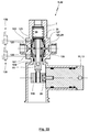
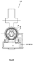
- Fig. 22 shows a further embodiment of a level control valve 6 in a longitudinal section.
- the drive element 13 formed by the drive shaft 11 drives the valve element 23 via an eccentric 25 without the interposition of a further transmission (such as a planetary gear 41).
- a further transmission such as a planetary gear 41.
- the valve element 23 as shown via a screw with a contact body 119 which is actuated by the eccentric 25 may be connected.
- the valve seat 35 is not formed by the housing 7 of the level control valve 6 for this embodiment, but rather by an actuating piston 120.
- the drive shaft 11 and the position of the valve element 23 correlated therewith are in a lower position as a function of the rotation the valve body 23 a vent, in the valve position according to Fig. 22 a shut-off of the bellows and in a relation to the valve position according to Fig. 22 lifted valve position ventilation of the bellows.
- the reference position here the blocking position according to Fig. 22 , Can be changed by the displacement of the actuating piston 120, which thus forms the responsible for the specification of the reference position counter-valve element 29.
- the adjusting piston 120 is formed with two telescopic and sleeve-like adjusting piston parts 131, 132.
- the radially inwardly disposed adjusting piston part 131 forms the valve seat 35 in the end region facing the valve disk 36.
- a spring 133 presses a shoulder 134 of the actuating piston part 131 against an inner collar 135 of the actuating piston part 132, whereby the actuating piston part 132 is pressed against a shoulder 136 of the housing 7. In this way, a first, lowermost reference position of the actuating piston part 131 is predetermined.
- a pressure chamber 137 can be pressurized.
- the pressure chamber 137 is limited by a piston surface 138 of the Stellkolbenteils 131.
- About the action of the pressure chamber 137 and caused on the piston surface 138 compressive force can be moved relative to the actuating piston member 132 against the action of the spring 133 of the actuating piston member 131 up to a Paragraph 139 of the Stellkolbenteils 131 comes to rest on an inner collar 140 of the Stellkolbenteils 132.
- a second, raised reference position is given.
- a third, further raised reference position are brought about, via the solenoid valve 130 is a pressurization of a pressure chamber 141, which is bounded by a formed of the lower end face of the Stellkolbenteils 132 piston surface 142.
- the pressure force generated here can, contrary to the action of the spring 133, lead to a common movement of the two adjusting piston parts 131, 132, in which case the shoulder 139 continues to rest on the inner collar 140.
- a further reference position can be brought about by pressurizing the pressure chamber 141 without pressurizing the pressure chamber 137. If further reference layers are to be able to be brought together, further sleeve-like adjusting piston parts nested with corresponding pressure chambers and associated solenoid valves can be nested accordingly be used.
- the embodiment according to Fig. 24 and 25 basically corresponds to the embodiment according to Fig. 6 , However, here a rotation of the drive shaft 53 is not brought about by means of an electric drive unit 54. Rather, here is the drive of the drive shaft 53 via a pneumatically operated actuator 143.
- the pneumatically operated actuator 143 to a vane motor 144 or a rotary piston engine 145.
- a control torque and / or an adjustment angle can / can be influenced pneumatically, which can be done via the solenoid valves 129, 130.
Landscapes
- Engineering & Computer Science (AREA)
- General Engineering & Computer Science (AREA)
- Mechanical Engineering (AREA)
- Vehicle Body Suspensions (AREA)
Priority Applications (7)
| Application Number | Priority Date | Filing Date | Title |
|---|---|---|---|
| EP16156357.2A EP3208120A1 (fr) | 2016-02-18 | 2016-02-18 | Dispositif de commande electronique et circuit de commande d'un systeme de suspension pneumatique d'un vehicule utilitaire |
| PL17703164.8T PL3416836T3 (pl) | 2016-02-18 | 2017-02-08 | Elektroniczne urządzenie sterujące i obwód sterujący do układu zawieszenia pneumatycznego pojazdu użytkowego |
| PCT/EP2017/052745 WO2017140552A1 (fr) | 2016-02-18 | 2017-02-08 | Dispositif de commande électronique et circuit de commande pour système de suspension pneumatique d'un véhicule utilitaire |
| EP17703164.8A EP3416836B1 (fr) | 2016-02-18 | 2017-02-08 | Dispositif de commande electronique et circuit de commande d'un systeme de suspension pneumatique d'un vehicule utilitaire |
| CN201780013461.4A CN108698466B (zh) | 2016-02-18 | 2017-02-08 | 用于商用车空气悬架装置的电控制装置和控制回路 |
| HUE17703164A HUE060522T2 (hu) | 2016-02-18 | 2017-02-08 | Elektronikus vezérlõegység és vezérlõ áramkör használati jármû légrugós felfüggesztõ rendszeréhez |
| US16/105,291 US11207935B2 (en) | 2016-02-18 | 2018-08-20 | Electronic control device and control circuit for an air suspension system of a commercial vehicle |
Applications Claiming Priority (1)
| Application Number | Priority Date | Filing Date | Title |
|---|---|---|---|
| EP16156357.2A EP3208120A1 (fr) | 2016-02-18 | 2016-02-18 | Dispositif de commande electronique et circuit de commande d'un systeme de suspension pneumatique d'un vehicule utilitaire |
Publications (2)
| Publication Number | Publication Date |
|---|---|
| EP3208120A1 true EP3208120A1 (fr) | 2017-08-23 |
| EP3208120A8 EP3208120A8 (fr) | 2017-10-11 |
Family
ID=55404610
Family Applications (2)
| Application Number | Title | Priority Date | Filing Date |
|---|---|---|---|
| EP16156357.2A Withdrawn EP3208120A1 (fr) | 2016-02-18 | 2016-02-18 | Dispositif de commande electronique et circuit de commande d'un systeme de suspension pneumatique d'un vehicule utilitaire |
| EP17703164.8A Active EP3416836B1 (fr) | 2016-02-18 | 2017-02-08 | Dispositif de commande electronique et circuit de commande d'un systeme de suspension pneumatique d'un vehicule utilitaire |
Family Applications After (1)
| Application Number | Title | Priority Date | Filing Date |
|---|---|---|---|
| EP17703164.8A Active EP3416836B1 (fr) | 2016-02-18 | 2017-02-08 | Dispositif de commande electronique et circuit de commande d'un systeme de suspension pneumatique d'un vehicule utilitaire |
Country Status (6)
| Country | Link |
|---|---|
| US (1) | US11207935B2 (fr) |
| EP (2) | EP3208120A1 (fr) |
| CN (1) | CN108698466B (fr) |
| HU (1) | HUE060522T2 (fr) |
| PL (1) | PL3416836T3 (fr) |
| WO (1) | WO2017140552A1 (fr) |
Cited By (3)
| Publication number | Priority date | Publication date | Assignee | Title |
|---|---|---|---|---|
| WO2019213387A1 (fr) * | 2018-05-04 | 2019-11-07 | Hendrickson Usa, L.L.C. | Système de commande pneumatique pour véhicules et autres structures chargées |
| CN113710513A (zh) * | 2019-02-15 | 2021-11-26 | 克诺尔商用车制动系统有限公司 | 气动控制单元 |
| CN113696691A (zh) * | 2021-08-23 | 2021-11-26 | 岚图汽车科技有限公司 | 空气悬架系统和车辆 |
Families Citing this family (12)
| Publication number | Priority date | Publication date | Assignee | Title |
|---|---|---|---|---|
| EP3208119A1 (fr) * | 2016-02-18 | 2017-08-23 | Haldex Brake Products Aktiebolag | Dispositif de vanne de controle de niveau actionne mecaniquement |
| US11679637B2 (en) * | 2016-06-27 | 2023-06-20 | Steve N. G. SIMON | Retrofit for farm equipment |
| CN109532377A (zh) * | 2018-11-12 | 2019-03-29 | 珠海格力电器股份有限公司 | 一种汽车控制方法、装置、存储介质及汽车 |
| EP4001691B1 (fr) * | 2019-07-17 | 2025-05-07 | Hitachi Astemo, Ltd. | Amortisseur de chocs |
| GB2604845B (en) * | 2020-10-26 | 2024-06-19 | Haldex Ab | Vehicle suspension apparatus |
| EP4000969A3 (fr) * | 2020-11-16 | 2022-06-08 | Steve N.G. Simon | Rénovation pour équipement agricole |
| CN113415113B (zh) * | 2021-07-05 | 2023-10-31 | 襄阳国铁机电股份有限公司 | 一种公铁两用检测车摩擦轮驱动路轨系统 |
| DE102022105565A1 (de) | 2022-03-09 | 2023-09-14 | Bürkert Werke GmbH & Co. KG | Pneumatisch gesteuerte Ventileinheit, Ventilanlage und Verfahren zum Betreiben einer Ventileinheit |
| EP4306345B1 (fr) * | 2022-07-11 | 2025-09-10 | Volvo Truck Corporation | Valve de mise à niveau pour un système de suspension pneumatique et le véhicule |
| CN115489499A (zh) * | 2022-09-28 | 2022-12-20 | 山东安顺制动系统有限公司 | 制动阀缓冲腔调压机构的控制方法 |
| GB2637321A (en) * | 2024-01-16 | 2025-07-23 | Haldex Ab | A valve assembly |
| US20250319732A1 (en) * | 2024-04-10 | 2025-10-16 | Ford Global Technologies, Llc | Methods and apparatus to facilitate loading and unloading a vehicle |
Citations (24)
| Publication number | Priority date | Publication date | Assignee | Title |
|---|---|---|---|---|
| GB2237780A (en) | 1989-11-07 | 1991-05-15 | Rubery Owen Rockwell Ltd | Height control of air-suspended vehicles |
| US5016912A (en) | 1989-02-22 | 1991-05-21 | Dbx Corporation | Trailer suspension apparatus |
| DE4120824C1 (fr) | 1991-06-24 | 1992-06-17 | Grau Gmbh, 6900 Heidelberg, De | |
| DE4202729C2 (de) | 1991-06-24 | 1993-11-25 | Grau Gmbh | Steueranlage zum willkürlichen Heben und Senken des Fahrzeugaufbaus von luftgefederten Fahrzeugen |
| GB2280877A (en) | 1993-08-12 | 1995-02-15 | M & G Tankers & Trailers Ltd | Height control for vehicle air suspension |
| DE4414868C1 (de) * | 1994-04-28 | 1995-05-11 | Grau Gmbh | Steueranlage zum willkürlichen Heben und Senken des Fahrzeugaufbaus von luftgefederten Fahrzeugen |
| JPH0891034A (ja) * | 1994-09-28 | 1996-04-09 | Nissan Diesel Motor Co Ltd | 車両用エアサスペンション装置 |
| DE19916040A1 (de) | 1999-04-09 | 2000-10-12 | Knorr Bremse Systeme | Ventilvorrichtung zum Heben und Senken von luftgefederten Anhänger-Fahrzeugen |
| DE19944873C1 (de) | 1999-09-18 | 2001-01-04 | Haldex Brake Prod Gmbh | Steueranlage zum Heben und Senken des Fahrzeugaufbaus von luftgefederten Fahrzeugen mit Niveauregelung |
| DE10129143C1 (de) | 2001-06-16 | 2002-06-13 | Haldex Brake Prod Gmbh | Pneumatisches Schaltventil für Anlagen zum Heben und Senken des Fahrzeugaufbaus von luftgefederten Fahrzeugen |
| JP2002293122A (ja) * | 2001-03-30 | 2002-10-09 | Nissan Diesel Motor Co Ltd | 速度感応式車高調整機構及び制御方法 |
| EP1382469A2 (fr) | 2002-07-18 | 2004-01-21 | Haldex Brake Products GmbH | Electrovanne pour véhicule utilitaire à suspension pneumatique |
| DE102005017590B3 (de) | 2005-04-16 | 2006-06-14 | Haldex Brake Products Gmbh | Umschaltventil für Anlagen mit einem Niveauregelventil zum gesteuerten Konstanthalten der Höhe eines Kraftfahrzeugs |
| DE102005017591B3 (de) | 2005-04-16 | 2006-06-22 | Haldex Brake Products Gmbh | Steueranlage für den Aufbau eines luftgefederten Kraftfahrzeuges, mit einem Niveauregelventil mit zwei Luftfederkreisen |
| DE102005019479B3 (de) | 2005-04-27 | 2007-01-18 | Haldex Brake Products Gmbh | Anhängerbremsventil für einen Kraftfahrzeug-Anhänger |
| DE60031554T2 (de) | 1999-08-24 | 2007-08-16 | Haldex Brake Corp. | Niveauregelventil für längsarmaufhängung |
| DE102006006439B4 (de) | 2006-02-13 | 2008-11-27 | Wabco Gmbh | Ventileinrichtung zur manuellen Veränderung der Niveaulage eines luftgefederten Fahrzeuges |
| EP1687160B1 (fr) | 2003-11-19 | 2009-04-01 | WABCO GmbH | Systeme de suspension pneumatique pour vehicule |
| EP1712380B1 (fr) | 2005-04-16 | 2010-01-06 | Haldex Brake Products GmbH | Vanne de commutation pour soulever et baisser une carrosserie de véhicule |
| KR20100127395A (ko) * | 2009-05-26 | 2010-12-06 | (주)보창산업 | 차고 조절이 용이한 하이브리드 에어 서스펜션 |
| US7878065B2 (en) | 2007-10-31 | 2011-02-01 | Hong Fu Jin Precision Industry (Shenzhen) Co., Ltd. | Ultrasonic inspection apparatus |
| US20120146307A1 (en) | 2009-08-25 | 2012-06-14 | Seok Hwan Kim | Multiple ride height control apparatus for air suspension |
| WO2014124944A1 (fr) | 2013-02-12 | 2014-08-21 | Haldex Brake Products Gmbh | Système de suspension de véhicule |
| DE102014103842A1 (de) | 2014-03-20 | 2015-09-24 | Knorr-Bremse Systeme für Nutzfahrzeuge GmbH | Vorrichtung zur Steuerung von pneumatischen Einrichtungen eines Anhängers für ein Nutzfahrzeug |
Family Cites Families (5)
| Publication number | Priority date | Publication date | Assignee | Title |
|---|---|---|---|---|
| CN201095298Y (zh) * | 2007-11-20 | 2008-08-06 | 黄忠祥 | 车用空气悬挂电子控制装置 |
| DE102011121755A1 (de) * | 2011-12-21 | 2013-06-27 | Wabco Gmbh | Luftfederungsanlage eines Kraftfahrzeugs und Verfahren zu deren Steuerung |
| CN103568764A (zh) * | 2012-07-30 | 2014-02-12 | 泰州市海陵区昊星汽车电子科技有限公司 | 一种牵引车用高度升降调整器 |
| CN103085628B (zh) * | 2013-01-25 | 2016-02-24 | 中国公路车辆机械有限公司 | 一种客车空气悬架控制系统 |
| CN204161031U (zh) * | 2014-09-04 | 2015-02-18 | 青岛浩釜铭车辆科技有限公司 | 空气弹簧压力平衡阀 |
-
2016
- 2016-02-18 EP EP16156357.2A patent/EP3208120A1/fr not_active Withdrawn
-
2017
- 2017-02-08 HU HUE17703164A patent/HUE060522T2/hu unknown
- 2017-02-08 WO PCT/EP2017/052745 patent/WO2017140552A1/fr not_active Ceased
- 2017-02-08 EP EP17703164.8A patent/EP3416836B1/fr active Active
- 2017-02-08 PL PL17703164.8T patent/PL3416836T3/pl unknown
- 2017-02-08 CN CN201780013461.4A patent/CN108698466B/zh not_active Expired - Fee Related
-
2018
- 2018-08-20 US US16/105,291 patent/US11207935B2/en active Active
Patent Citations (27)
| Publication number | Priority date | Publication date | Assignee | Title |
|---|---|---|---|---|
| US5016912A (en) | 1989-02-22 | 1991-05-21 | Dbx Corporation | Trailer suspension apparatus |
| GB2237780A (en) | 1989-11-07 | 1991-05-15 | Rubery Owen Rockwell Ltd | Height control of air-suspended vehicles |
| DE4120824C1 (fr) | 1991-06-24 | 1992-06-17 | Grau Gmbh, 6900 Heidelberg, De | |
| DE4202729C2 (de) | 1991-06-24 | 1993-11-25 | Grau Gmbh | Steueranlage zum willkürlichen Heben und Senken des Fahrzeugaufbaus von luftgefederten Fahrzeugen |
| EP0520147B1 (fr) | 1991-06-24 | 1995-07-19 | Grau Gmbh | Dispositif de commande volontaire de montée ou de descente de la carrosserie de véhicules à suspension pneumatique |
| EP0520148B1 (fr) | 1991-06-24 | 1998-03-11 | Grau Gmbh | Soupape pneumatique de commutation pour dispositfs de soulèvement ou d'abaissement de la carrosserie de véhicules à suspension pneumatique |
| GB2280877A (en) | 1993-08-12 | 1995-02-15 | M & G Tankers & Trailers Ltd | Height control for vehicle air suspension |
| DE4414868C1 (de) * | 1994-04-28 | 1995-05-11 | Grau Gmbh | Steueranlage zum willkürlichen Heben und Senken des Fahrzeugaufbaus von luftgefederten Fahrzeugen |
| JPH0891034A (ja) * | 1994-09-28 | 1996-04-09 | Nissan Diesel Motor Co Ltd | 車両用エアサスペンション装置 |
| DE19916040A1 (de) | 1999-04-09 | 2000-10-12 | Knorr Bremse Systeme | Ventilvorrichtung zum Heben und Senken von luftgefederten Anhänger-Fahrzeugen |
| DE60031554T2 (de) | 1999-08-24 | 2007-08-16 | Haldex Brake Corp. | Niveauregelventil für längsarmaufhängung |
| DE19944873C1 (de) | 1999-09-18 | 2001-01-04 | Haldex Brake Prod Gmbh | Steueranlage zum Heben und Senken des Fahrzeugaufbaus von luftgefederten Fahrzeugen mit Niveauregelung |
| JP2002293122A (ja) * | 2001-03-30 | 2002-10-09 | Nissan Diesel Motor Co Ltd | 速度感応式車高調整機構及び制御方法 |
| DE10129143C1 (de) | 2001-06-16 | 2002-06-13 | Haldex Brake Prod Gmbh | Pneumatisches Schaltventil für Anlagen zum Heben und Senken des Fahrzeugaufbaus von luftgefederten Fahrzeugen |
| EP1382469A2 (fr) | 2002-07-18 | 2004-01-21 | Haldex Brake Products GmbH | Electrovanne pour véhicule utilitaire à suspension pneumatique |
| EP1687160B1 (fr) | 2003-11-19 | 2009-04-01 | WABCO GmbH | Systeme de suspension pneumatique pour vehicule |
| EP1712380B1 (fr) | 2005-04-16 | 2010-01-06 | Haldex Brake Products GmbH | Vanne de commutation pour soulever et baisser une carrosserie de véhicule |
| DE102005017590B3 (de) | 2005-04-16 | 2006-06-14 | Haldex Brake Products Gmbh | Umschaltventil für Anlagen mit einem Niveauregelventil zum gesteuerten Konstanthalten der Höhe eines Kraftfahrzeugs |
| DE102005017591B3 (de) | 2005-04-16 | 2006-06-22 | Haldex Brake Products Gmbh | Steueranlage für den Aufbau eines luftgefederten Kraftfahrzeuges, mit einem Niveauregelventil mit zwei Luftfederkreisen |
| EP2067638B1 (fr) | 2005-04-16 | 2010-08-18 | Haldex Brake Products GmbH | Vanne de commutation pour soulever et baisser une carrosserie de véhicule |
| DE102005019479B3 (de) | 2005-04-27 | 2007-01-18 | Haldex Brake Products Gmbh | Anhängerbremsventil für einen Kraftfahrzeug-Anhänger |
| DE102006006439B4 (de) | 2006-02-13 | 2008-11-27 | Wabco Gmbh | Ventileinrichtung zur manuellen Veränderung der Niveaulage eines luftgefederten Fahrzeuges |
| US7878065B2 (en) | 2007-10-31 | 2011-02-01 | Hong Fu Jin Precision Industry (Shenzhen) Co., Ltd. | Ultrasonic inspection apparatus |
| KR20100127395A (ko) * | 2009-05-26 | 2010-12-06 | (주)보창산업 | 차고 조절이 용이한 하이브리드 에어 서스펜션 |
| US20120146307A1 (en) | 2009-08-25 | 2012-06-14 | Seok Hwan Kim | Multiple ride height control apparatus for air suspension |
| WO2014124944A1 (fr) | 2013-02-12 | 2014-08-21 | Haldex Brake Products Gmbh | Système de suspension de véhicule |
| DE102014103842A1 (de) | 2014-03-20 | 2015-09-24 | Knorr-Bremse Systeme für Nutzfahrzeuge GmbH | Vorrichtung zur Steuerung von pneumatischen Einrichtungen eines Anhängers für ein Nutzfahrzeug |
Cited By (5)
| Publication number | Priority date | Publication date | Assignee | Title |
|---|---|---|---|---|
| WO2019213387A1 (fr) * | 2018-05-04 | 2019-11-07 | Hendrickson Usa, L.L.C. | Système de commande pneumatique pour véhicules et autres structures chargées |
| CN113710513A (zh) * | 2019-02-15 | 2021-11-26 | 克诺尔商用车制动系统有限公司 | 气动控制单元 |
| CN113710513B (zh) * | 2019-02-15 | 2024-02-23 | 克诺尔商用车制动系统有限公司 | 气动控制单元 |
| CN113696691A (zh) * | 2021-08-23 | 2021-11-26 | 岚图汽车科技有限公司 | 空气悬架系统和车辆 |
| CN113696691B (zh) * | 2021-08-23 | 2024-01-09 | 岚图汽车科技有限公司 | 空气悬架系统和车辆 |
Also Published As
| Publication number | Publication date |
|---|---|
| US11207935B2 (en) | 2021-12-28 |
| EP3416836A1 (fr) | 2018-12-26 |
| PL3416836T3 (pl) | 2023-01-23 |
| WO2017140552A1 (fr) | 2017-08-24 |
| EP3208120A8 (fr) | 2017-10-11 |
| US20180354333A1 (en) | 2018-12-13 |
| CN108698466A (zh) | 2018-10-23 |
| EP3416836B1 (fr) | 2022-09-28 |
| CN108698466B (zh) | 2022-03-18 |
| HUE060522T2 (hu) | 2023-03-28 |
Similar Documents
| Publication | Publication Date | Title |
|---|---|---|
| EP3416836B1 (fr) | Dispositif de commande electronique et circuit de commande d'un systeme de suspension pneumatique d'un vehicule utilitaire | |
| EP3416837B1 (fr) | Dispositif de vanne de controle de niveau actionne mecaniquement | |
| EP3967561B1 (fr) | Équipement d'air comprimé de remorque de véhicule utilitaire | |
| DE102009045191C5 (de) | Verfahren zum Betrieb einer Bremseinrichtung für ein hydraulisch gebremstes Zugfahrzeug | |
| EP2125398B1 (fr) | Système de suspension pneumatique pourvu de soupapes de commande actionnées exclusivement par un fluide sous pression | |
| EP2757006B1 (fr) | Système de soupape pour une installation d'air comprimé d'une remorque de véhicule utilitaire | |
| EP2934971B1 (fr) | Procédé pour utiliser un véhicule présentant un mode de conduite autonome, unité de commande pour un dispositif de frein de stationnement du véhicule, ainsi que dispositif de frein de stationnement, installation de freinage et véhicule qui en est équipé | |
| EP2540537B1 (fr) | Installation de ressort pneumatique pour un véhicule utilitaire | |
| EP2263892A1 (fr) | Unité de vanne de commande destinée à aérer et ventiler des soufflets à ressort d'un véhicule ou d'une remorque | |
| WO2009039908A1 (fr) | Ensemble soupape pour un système de suspension pneumatique | |
| EP2540538B1 (fr) | Installation de ressort pneumatique | |
| EP2263893A1 (fr) | Unité de vanne de commande destinée à aérer et ventiler des soufflets à ressort d'un véhicule ou d'une remorque | |
| DE3636260C2 (fr) | ||
| DE4327764C2 (de) | Luftfederungsanlage | |
| EP3967562B1 (fr) | Équipement à air comprimé pour une remorque | |
| EP2159461B1 (fr) | Installation de levage et d'abaissement d'une structure de véhicule | |
| EP3730321B1 (fr) | Installation de commande de la pression de pneu pour véhicule agricole | |
| EP2177381B1 (fr) | Ensemble de clapets pour un système de suspension pneumatique | |
| EP4375092A1 (fr) | Ensemble valve de pression de pneu et groupe comprenant des ensembles valve de pression de pneu | |
| EP2754916B1 (fr) | Unité d'amortisseur pneumatique pour une installation d'amortisseur pneumatique d'un véhicule | |
| DE4414868C1 (de) | Steueranlage zum willkürlichen Heben und Senken des Fahrzeugaufbaus von luftgefederten Fahrzeugen | |
| DE2318535A1 (de) | Luftfederungsventil fuer fahrzeuge, insbesondere fuer container-fahrzeuge | |
| EP2177382B1 (fr) | Agencement de clapet doté d'une première et d'une deuxième soupape à siège, ainsi qu'un dispositif de clapet doté d'un tel agencement de clapet | |
| EP2957441B1 (fr) | Installation de ressort pneumatique destinée à lever et à abaisser une caisse de véhicule | |
| EP2179872A1 (fr) | Système de suspension pneumatique avec une mécanisme de commande électromécanique pour repositionner un distributeur de commande dans la position de roulage |
Legal Events
| Date | Code | Title | Description |
|---|---|---|---|
| PUAI | Public reference made under article 153(3) epc to a published international application that has entered the european phase |
Free format text: ORIGINAL CODE: 0009012 |
|
| 17P | Request for examination filed |
Effective date: 20170202 |
|
| AK | Designated contracting states |
Kind code of ref document: A1 Designated state(s): AL AT BE BG CH CY CZ DE DK EE ES FI FR GB GR HR HU IE IS IT LI LT LU LV MC MK MT NL NO PL PT RO RS SE SI SK SM TR |
|
| AX | Request for extension of the european patent |
Extension state: BA ME |
|
| RIN1 | Information on inventor provided before grant (corrected) |
Inventor name: HEER, SIEGFRIED Inventor name: SULZYC, GEORG Inventor name: SCHERING, CHRISTIAN Inventor name: HARRISON, DUDLEY Inventor name: MELLINGS, CARL |
|
| STAA | Information on the status of an ep patent application or granted ep patent |
Free format text: STATUS: THE APPLICATION IS DEEMED TO BE WITHDRAWN |
|
| 18D | Application deemed to be withdrawn |
Effective date: 20180901 |