EP3208142A1 - Dispositif de support de siège d'enfant - Google Patents
Dispositif de support de siège d'enfant Download PDFInfo
- Publication number
- EP3208142A1 EP3208142A1 EP15850229.4A EP15850229A EP3208142A1 EP 3208142 A1 EP3208142 A1 EP 3208142A1 EP 15850229 A EP15850229 A EP 15850229A EP 3208142 A1 EP3208142 A1 EP 3208142A1
- Authority
- EP
- European Patent Office
- Prior art keywords
- child seat
- movable portion
- support device
- fixed
- seat support
- Prior art date
- Legal status (The legal status is an assumption and is not a legal conclusion. Google has not performed a legal analysis and makes no representation as to the accuracy of the status listed.)
- Granted
Links
Images







Classifications
-
- B—PERFORMING OPERATIONS; TRANSPORTING
- B60—VEHICLES IN GENERAL
- B60N—SEATS SPECIALLY ADAPTED FOR VEHICLES; VEHICLE PASSENGER ACCOMMODATION NOT OTHERWISE PROVIDED FOR
- B60N2/00—Seats specially adapted for vehicles; Arrangement or mounting of seats in vehicles
- B60N2/24—Seats specially adapted for vehicles; Arrangement or mounting of seats in vehicles for particular purposes or particular vehicles
- B60N2/26—Seats specially adapted for vehicles; Arrangement or mounting of seats in vehicles for particular purposes or particular vehicles for children
- B60N2/28—Seats readily mountable on, and dismountable from, existing seats or other parts of the vehicle
- B60N2/2821—Seats readily mountable on, and dismountable from, existing seats or other parts of the vehicle having a seat and a base part
- B60N2/2824—Seats readily mountable on, and dismountable from, existing seats or other parts of the vehicle having a seat and a base part part of the base being supported by the vehicle frame
-
- B—PERFORMING OPERATIONS; TRANSPORTING
- B60—VEHICLES IN GENERAL
- B60N—SEATS SPECIALLY ADAPTED FOR VEHICLES; VEHICLE PASSENGER ACCOMMODATION NOT OTHERWISE PROVIDED FOR
- B60N2/00—Seats specially adapted for vehicles; Arrangement or mounting of seats in vehicles
- B60N2/24—Seats specially adapted for vehicles; Arrangement or mounting of seats in vehicles for particular purposes or particular vehicles
- B60N2/26—Seats specially adapted for vehicles; Arrangement or mounting of seats in vehicles for particular purposes or particular vehicles for children
- B60N2/28—Seats readily mountable on, and dismountable from, existing seats or other parts of the vehicle
-
- B—PERFORMING OPERATIONS; TRANSPORTING
- B60—VEHICLES IN GENERAL
- B60N—SEATS SPECIALLY ADAPTED FOR VEHICLES; VEHICLE PASSENGER ACCOMMODATION NOT OTHERWISE PROVIDED FOR
- B60N2/00—Seats specially adapted for vehicles; Arrangement or mounting of seats in vehicles
- B60N2/24—Seats specially adapted for vehicles; Arrangement or mounting of seats in vehicles for particular purposes or particular vehicles
- B60N2/26—Seats specially adapted for vehicles; Arrangement or mounting of seats in vehicles for particular purposes or particular vehicles for children
- B60N2/28—Seats readily mountable on, and dismountable from, existing seats or other parts of the vehicle
- B60N2/2884—Seats readily mountable on, and dismountable from, existing seats or other parts of the vehicle with protection systems against abnormal g-forces
Definitions
- the present invention relates to a child seat support device that prevents a child seat placed on a vehicle seat from falling forward in case of a sudden braking, a collision, or a similar accident.
- a child seat placed on a vehicle seat is used by fixing a seat body with a vehicle seat belt. Due to an influence of an inertia force generated during braking, the child seat fixed to the vehicle seat moves so as to fall forward with a site near a rear end of a seat base as a base point.
- the child seat includes a support device to reduce a sinking of a front side of the seat base.
- a child seat support device disclosed in Patent Document 1 has been known.
- the child seat support device disclosed in Patent Document 1 is basically constituted of a horizontal member and a vertical member.
- the horizontal member projects to a front side of a seat base.
- the vertical member can incline and fall down to the seat base side with this horizontal member as a base point.
- the child seat support device with such basic configuration adjusts an angle and a length of the vertical member and causes a distal end of the vertical member to abut on a vehicle floor to ensure providing an effect of preventing a child seat from falling down.
- the vertical member is constituted of an outer tube and an inner tube.
- the length of the vertical member is adjustable by the inner tube coming in and out an inside of the outer tube.
- the inner tube has a plurality of positioning holes. Inserting a positioning pin disposed at the outer tube to any one of the positioning holes ensures determining the length of the vertical member.
- Patent Document 1 Japanese Patent No. 4898037
- Patent Document 1 The use of the child seat support device disclosed in Patent Document 1 allows preventing the child seat from inclining and falling down in case of a sudden braking or a similar accident.
- a conventional child seat support device such as the child seat support device disclosed in Patent Document 1 is required to manually adjust the length of the vertical member by a person in charge of mounting when the child seat is mounted to the vehicle seat.
- the person in charge of mounting does not appropriately adjust the child seat support device when the child seat is mounted to the vehicle seat, the child seat support device cannot provide the function, thereby involving a hazard.
- An object of the present invention is to provide a child seat support device that eliminates the need for adjustment by a person in charge of mounting to ensure an improvement in safety.
- a child seat support device to achieve the object is a seat support device for a child seat placed on a seat cushion of a vehicle seat and fixed to the vehicle seat.
- the child seat support device includes a fixed portion and a movable portion.
- the fixed portion is fixed to the child seat.
- the movable portion is supported via the fixed portion.
- the movable portion extends to a vehicle floor.
- the movable portion includes an automatic adjustment mechanism and a lock mechanism.
- the automatic adjustment mechanism changes a length of the movable portion from the fixed portion according to a height of the vehicle floor to bring a lower end portion of the movable portion into abutment with the vehicle floor.
- the lock mechanism stops an operation of the automatic adjustment mechanism in association with a change in acceleration of a vehicle.
- the child seat support device having the above-described features can be configured as follows.
- the automatic adjustment mechanism is constituted of biasing means that presses the movable portion to the vehicle floor side.
- the feature allows the distal end of the movable portion to be brought into abutment with the vehicle floor reliably compared with the case of abutment only by own weight of the movable portion. That is, this improves ground following capability of the automatic adjustment mechanism to the height of the vehicle floor.
- the child seat support device having the above-described features may be configured as follows.
- the lock mechanism operates by inclining the movable portion pressed to the vehicle floor side.
- configuring the movable portion so as to be inclined in association with the change in acceleration caused by the sudden braking and the collision eliminates the need for providing a switch to operate the lock mechanism, ensuring the simple configuration.
- the child seat support device having the above-described features can be configured as follows.
- the movable portion has a hole on a side surface.
- the lock mechanism operates by inserting a stopper fixed via the fixed portion into the hole. This feature reliably works the lock mechanism.
- the child seat support device having the above-described features can be configured as follows.
- the movable portion has a wave-shaped surface on a side surface.
- the lock mechanism operates by fitting a stopper fixed via the fixed portion to the wave-shaped surface. This mechanism ensures narrowing a fitting interval compared with the case of the insertion of the stopper to the hole. Accordingly, a time until the lock mechanism acts can be shortened.
- the child seat support device having the above-described features can be configured as follows.
- the movable portion has a convex-shaped teeth portion on a side surface.
- the lock mechanism operates by inserting the teeth portion into a stopper fixed via the fixed portion. This feature also ensures reliably working the lock mechanism between the teeth portion and the stopper.
- the child seat support device having the above-described features can be configured as follows.
- the movable portion has a friction surface on a side surface.
- the lock mechanism operates by bringing a stopper fixed via the fixed portion into abutment with the friction surface. This feature works the lock mechanism when the friction surface abuts on the stopper. Accordingly, a time lag from when the sudden braking or the collusion occurs until the lock mechanism works can be significantly shortened.
- the child seat support device having the above-described features can be configured as follows.
- the fixed portion internally houses a part of the movable portion. This configuration ensures the slim support device and a weight reduction of the support device while achieving fixing the safety.
- the child seat support device having the above-described features may be configured as follows.
- the fixed portion has a through-hole on a side surface.
- the lock mechanism operates by inserting a stopper disposed at the movable portion into the through-hole. This feature can also reliably act the lock mechanism.
- the child seat support device with the above-described features eliminates the need for adjustment of the length of the support device by the person in charge of mounting who installs the child seat to the vehicle seat to ensure an improvement in safety.
- a child seat 50 that applies the child seat support device according to the present invention (hereinafter simply referred to as a support device 10) includes a base 52 and a seat body 54.
- the support device 10 according to the embodiments includes fixed portions 12 and a movable portion 14.
- the fixed portions 12 are members fixed to the base 52 of the child seat 50.
- the fixed portion 12 has an approximately L-shaped structure. After the fixed portion 12 extends from the base 52 to a front side of the child seat 50 (horizontal direction), the fixed portion 12 extends to a vehicle floor side (lower side). In the example illustrated in Fig. 3 , the fixed portions 12 are disposed as a pair of two.
- the fixed portions 12 include a support case 24 to support the movable portion 14 at the distal end side.
- the movable portion 14 is a support leg that allows sliding of the support case 24 in a vehicle floor direction.
- the movable portion 14 is configured to have a prismatic outline.
- a slit 16 formed along a longitudinal direction of the movable portion 14 and a plurality of through-holes 18 are disposed on a mounting back surface side.
- the through-holes 18 are disposed at both sides (only one side in Fig. 1 because Fig. 1 illustrates a partial cross section) on the slit 16.
- Abeam 20 is disposed on an inner upper end side of the movable portion 14.
- the slit 16 is an element to vertically move the movable portion 14 while causing a hook 26c provided at the support case 24, which will be described in detail later, to interpose to an inside of the movable portion 14.
- the plurality of through-holes 18 are elements into which a stopper 36 interposes at an operation of a lock mechanism.
- the beam 20 is an element to dispose a spring 22 as biasing means, which has a repulsion force to a tensile side, between itself and the hook 26c interposed in the slit 16.
- the support case 24 includes a casing 26, an upper plate 28, an under plate 30, a lock plate 32, and a pressing plate 34.
- the casing 26 is an outline formed of a front cover 26a and a back cover 26b.
- the casing 26 internally houses the components as described above, a part of the fixed portion, and a part of the movable portion.
- the back cover 26b includes the hook 26c to lock the spring 22.
- the upper plate 28 and the under plate 30 are support plates constituted of a pair of two.
- both the upper plate 28 and the under plate 30 include two fixed portion insertion holes 28a and 30a and one movable portion insertion holes 28b and 30b. Differentiating sizes of the fixed portion insertion holes 28a and 30a at the upper plate 28 and the under plate 30 is unnecessary.
- the movable portion insertion holes 28b and 30b an opening width positioned in a thickness direction of the casing 26 of the movable portion insertion hole 28b disposed at the upper plate 28 is formed larger than that of the movable portion insertion hole 30b disposed at the under plate 30. This is because of the following.
- the movable portion 14 inserted into the movable portion insertion holes 28b and 30b can be inclined in the thickness direction of the casing 26 with the under plate 30 side as a fulcrum.
- the upper plate 28 and the under plate 30 are formed of a member with high rigidity such as a metal material. This configuration allows reducing a breakage when stress is applied in case of a sudden braking, a collision, or a similar accident.
- the lock plate 32 is a plate that includes the stopper 36 to operate the lock mechanism.
- the lock plate 32 includes positioning pieces 32a, in addition to the claw-formed stopper 36.
- the stopper 36 is inserted into the through-holes 18, which are disposed on the mounting back surface of the movable portion 14, to be in charge of an action to stop the sliding of the movable portion 14.
- the positioning pieces 32a are elements to prevent a displacement and an inclination of the stopper 36.
- Fig. 4 and Fig. 5 with the movable portion 14 in the vertical state (along the front cover 26a), the stopper 36 of the lock plate 32 is not inserted into the through-holes 18.
- the lock plate 32 is positioned such that the stopper 36 is inserted into the through-holes 18 when the movable portion 14 inclines.
- the pressing plate 34 is a biasing member to prevent the movable portion 14 from inclining to the back cover 26b side in a steady state during which a change in acceleration in association with the sudden braking and the collision does not occur.
- the pressing plate 34 is disposed on the back cover 26b side of the casing 26.
- Springs 38 having a repulsion force to a compression side are disposed between the back cover 26b and the pressing plate 34. This configuration presses the pressing plate 34 to the front cover 26a side, thereby ensuring reducing the pressing plate 34 falling down to the back cover 26b side in the steady state.
- the support case 24 including such basic elements is preferably installed on a lower side with respect to a horizontal line L with a fixed point O with respect to the vehicle seat as the base point because of the following.
- a rotation force Fr caused by an inertia force F in association with the change in acceleration attempts to enter into a side opposite to a running direction. Accordingly, disposing the support case 24 on the lower side with respect to the horizontal line L eases obtaining the inclination of the movable portion 14 caused by the rotation force Fr.
- the support device 10 In the steady state where the change in acceleration in association with the sudden braking and the collision does not occur, the support device 10 with such basic configuration maintains the state of the movable portion 14 going along the front cover 26a of the casing 26.
- the action of the spring 22 applies the pressing force to the vehicle floor side to the movable portion 14.
- the movable portion 14 in the steady state slides with the support case 24 as the base point.
- the movable portion 14 works the automatic adjustment mechanism that automatically adjusts the length of the movable portion 14 so as to contact the vehicle floor.
- the strong inertia force F acts on the child seat 50.
- the child seat 50 on which a child (not illustrated) is seated is fixed to the vehicle seat with an ISO-FIX connector or a vehicle seat belt (neither of which are illustrated).
- the rotation force Fr that causes the child seat 50 to sink into the front side with the fixed point O with respect to the vehicle seat as the base point is applied.
- the support case 24 in the support device 10 is positioned on a vehicle running direction side with respect to the rotational center (fixed point O). Accordingly, the application of the rotation force Fr to the child seat 50 moves the support case 24 so as to sink into the vehicle floor side.
- a force in a rotation direction (inertia force Fr) to the vehicle floor side is applied to the movable portion 14 around the fixed point O of the child seat 50.
- a site of the movable portion 14 positioned upward (the fixed portion 12 side) with respect to the movable portion insertion hole 30b is inclined by being pressed to the back cover 26b side of the casing 26 with a force stronger than the pressing force by the pressing plate 34.
- the stopper 36 which is opposed to the mounting back surface of the movable portion 14, is inserted into the adjacent through-holes 18. Inserting the stopper 36 into the through-holes 18 with the movable portion 14 pressed to the back cover 26b side works the lock mechanism to stop the sinking of the support case 24 along the movable portion 14. This also stops the rotation (sinking) of the entire child seat 50.
- the movable portion 14 is slidable in the steady state, thereby allowing the automatic adjustment of the length so as to reach the vehicle floor. Meanwhile, the application of the inertia force F to the child seat 50 due to the sudden braking, the collusion, or a similar accident locks the movable portion 14, thus restraining the sinking of the child seat 50. Accordingly, the support device 10 according to the embodiments eliminates the need for the adjustment of the length of the support device (support leg) by a person in charge of mounting of the child seat 50. This ensures preventing an accident caused by an inappropriate installation state.
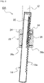
- a configuration of a support device 10A according to the embodiment is almost similar to the support device 10 according to the above-described first embodiment. The difference is that, the through-holes 18 disposed on the mounting back surface of the movable portion 14 are replaced by a wave-shaped surface 18a.
- the application of the wave-shaped surface 18a allows forming continuous concavities and convexities at intervals narrower than the through-holes 18. This ensures reducing the sinking of the child seat 50 caused by the sudden braking, the collision, or a similar accident to be smaller. Accordingly, the safety can be improved.
- the stopper 36 according to the embodiment has a distal end shape fittable to the concave portions of the wave-shaped surface 18a.
- the other configurations, actions, and effects are similar to those of the support device 10 according to the above-described first embodiment.
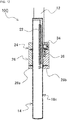
- a configuration of a support device 10B according to the embodiment is almost similar to the support devices 10 and 10A according to the above-described first and second embodiments. The difference is that, while the support devices 10 and 10A according to the first and the second embodiments include the through-holes 18 or the wave-shaped surface 18a, which include the holes and the concave portions, on the mounting back surface of the movable portion 14, the support device 10B according to the embodiment includes convex-shaped teeth portions 18b at the equivalent site.
- This embodiment configures the plurality of sawtooth-shaped teeth portions 18b continuous in the longitudinal direction of the movable portion 14.
- the stopper 36 has a form of having through-holes and concave portions to which the teeth portions 18b are fittable. Similar to the first and the second embodiments, this configuration also allows obtaining the automatic adjustment effect of the movable portion 14 in the steady state and the lock effect of the movable portion 14 in the abnormal state.
- the other configurations, actions, and effects are similar to those of the support devices 10 and 10A according to the above-described first and second embodiments.
- a configuration of a support device 10C according to the embodiment is almost similar to the support devices 10, 10A, and 10B according to the above-described first to third embodiments. The difference is in a structure of the mounting back surface of the movable portion 14.
- This embodiment includes a friction surface 18c on the mounting back surface.
- the stopper 36 is also constructed to have a friction surface abutting on this friction surface 18c.
- a child seat support device 10D according to a fifth embodiment of the present invention with reference to Fig. 14 and Fig. 15 .
- the support device 10D differs from the support devices 10, 10A, 10B, and 10C in the following configuration. That is, the support devices 10 to 10C according to the first to the fourth embodiments include the fixed portions 12 as a pair of two to support the one movable portion 14 via the support case 24. Meanwhile, the support device 10D according to the embodiment supports the one movable portion 14 with the one fixed portion 12.
- the support device 10D does not include the support case 24.
- both the fixed portion 12 and the movable portion 14 have the basic forms similar to those of the support devices 10 to 10C according to the above-described first to fourth embodiments. That is, the fixed portion 12 has a part extended to the vehicle running direction and a part extended to the vehicle floor side.
- the movable portion 14 has a straight structure.
- This embodiment employs a configuration of housing the movable portion 14 in the fixed portion 12. Therefore, a cross-sectional area of the fixed portion 12 is configured to be larger than a cross-sectional area of the movable portion 14. As illustrated in Fig. 15 , it is only necessary that a difference between the fixed portion 12 and the movable portion 14 in a cross-sectional width is provided such that at least the movable portion 14 housed in the fixed portion 12 can be inclined with a lower end of the fixed portion 12 as a base point.
- the movable portion 14 includes a stopper 36a and the fixed portion 12 includes through-holes 18d. Since the through-holes 18d are disposed in a direction that the distal end of the movable portion 14 falls down, the through-holes 18d are positioned on a back surface in a state of mounting the fixed portion 12.
- the stopper 36a is disposed on the distal end side of the movable portion 14.
- the pressing plate 34 is also disposed on the distal end side of the movable portion 14.
- a hook 12a is disposed on a lower end side of the fixed portion 12, and the beam 20 is disposed on a distal end side of the movable portion 14.
- a spring (not illustrated) as a biasing member is disposed between this hook 12a and the beam 20. This allows the movable portion 14 to be biased in the vehicle floor direction.
- the movable portion 14 includes a slit 16a on the mounting back surface side to cause the movable portion 14 to be slidable with the hook 12a inserted.
- this configuration also eliminates the need for the adjustment of the length of the support device (support leg) by the person in charge of mounting of the child seat. Accordingly, the safety can be improved.
- the lock mechanism may have the following configurations.
- Examples illustrated in Fig. 16 and Fig. 17 are support devices 10E of a type including the support case 24.
- the support device 10E employs not a claw but a pendulum 36b as the stopper.
- the movable portion 14 is supported so as not to be inclined with respect to the support case 24.
- the support device 10E with the configuration biases the movable portion 14 to the vehicle floor side in the steady state similar to the above-described embodiments, and the length of the movable portion 14 is automatically adjusted. Meanwhile, in case of the sudden braking, the collision, or a similar accident, the inertia force turns the pendulum 36b as the stopper in the running direction with the rotational center as the base point. The insertion of a distal end of the turning pendulum 36b into the through-hole 18, which is disposed on the mounting back surface of the movable portion 14, works the lock mechanism.
- the support device 10E with this configuration also eliminates the need for the adjustment of the length of the support device (support leg) by the person in charge of mounting of the child seat. Accordingly, the safety can be improved.
- a configuration where an element to constitute the stopper is inserted into the through-hole 18 formed on the mounting back surface of the movable portion 14 may employ not a passive operation but an active operation.
- the passive operation is operated by the use of the inertia force F like the examples illustrated in Fig. 16 and Fig. 17 .
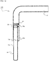
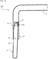
- the active operation includes driving means 42 as illustrated in Fig. 18 and Fig. 19 .
- the support case 24 internally includes a sensor 40, the driving means 42, and a lock pin 36c as the stopper.
- the sensor 40 is, for example, an acceleration sensor.
- the acceleration sensor When the acceleration detected by the acceleration sensor changes suddenly, the acceleration sensor outputs a drive signal to the driving means 42.
- the driving means 42 may be an air pressure system such as an inflator or may be an electromagnetic system. It is only necessary that the driving means 42 can operate by a reception of the drive signal to project the lock pin 36c mounted to the inside of the driving means 42.
- this configuration outputs the drive signal to the driving means 42.
- the driving means 42 that receives the drive signal operates to project the lock pin 36c.
- the lock pin 36c projected from the driving means 42 is inserted into the through-hole 18, which is formed on the mounting back surface of the movable portion 14, to work the lock function.
- the action of the spring 22 as the biasing means generates the function as the automatic adjustment mechanism.
- the function as the automatic adjustment mechanism may be generated by own weight of the movable portion 14.
Landscapes
- Engineering & Computer Science (AREA)
- Health & Medical Sciences (AREA)
- Child & Adolescent Psychology (AREA)
- General Health & Medical Sciences (AREA)
- Aviation & Aerospace Engineering (AREA)
- Transportation (AREA)
- Mechanical Engineering (AREA)
- Seats For Vehicles (AREA)
Applications Claiming Priority (2)
| Application Number | Priority Date | Filing Date | Title |
|---|---|---|---|
| JP2014209909A JP6420112B2 (ja) | 2014-10-14 | 2014-10-14 | チャイルドシート支持装置 |
| PCT/JP2015/073840 WO2016059880A1 (fr) | 2014-10-14 | 2015-08-25 | Dispositif de support de siège d'enfant |
Publications (3)
| Publication Number | Publication Date |
|---|---|
| EP3208142A1 true EP3208142A1 (fr) | 2017-08-23 |
| EP3208142A4 EP3208142A4 (fr) | 2017-11-22 |
| EP3208142B1 EP3208142B1 (fr) | 2018-11-28 |
Family
ID=55746428
Family Applications (1)
| Application Number | Title | Priority Date | Filing Date |
|---|---|---|---|
| EP15850229.4A Not-in-force EP3208142B1 (fr) | 2014-10-14 | 2015-08-25 | Dispositif de support de siège d'enfant |
Country Status (3)
| Country | Link |
|---|---|
| EP (1) | EP3208142B1 (fr) |
| JP (1) | JP6420112B2 (fr) |
| WO (1) | WO2016059880A1 (fr) |
Families Citing this family (4)
| Publication number | Priority date | Publication date | Assignee | Title |
|---|---|---|---|---|
| JP6974559B2 (ja) * | 2017-05-29 | 2021-12-01 | ニューウェルブランズ・ジャパン合同会社 | チャイルドシート |
| CN107380021B (zh) * | 2017-06-26 | 2023-08-04 | 好孩子儿童用品有限公司 | 一种儿童用品的支撑装置及儿童用品 |
| ES2806278T3 (es) * | 2017-09-14 | 2021-02-17 | Britax Roemer Kindersicherheit Gmbh | Pata de apoyo para un asiento de seguridad para niños |
| CN112641270B (zh) * | 2020-12-31 | 2023-10-24 | 安吉山业家居有限公司 | 一种儿童学习座椅的安全锁定结构 |
Family Cites Families (6)
| Publication number | Priority date | Publication date | Assignee | Title |
|---|---|---|---|---|
| JP4898037B2 (ja) * | 2001-09-25 | 2012-03-14 | コンビ株式会社 | チャイルドシートのサポートレッグ装置 |
| JP5596485B2 (ja) * | 2010-10-06 | 2014-09-24 | タカタ株式会社 | チャイルドシート |
| CN103507675B (zh) * | 2012-06-28 | 2016-01-13 | 宝钜儿童用品香港股份有限公司 | 儿童汽车椅支撑装置及儿童汽车安全椅 |
| CN103935272B (zh) * | 2013-01-18 | 2016-08-17 | 明门香港股份有限公司 | 儿童安全座椅 |
| CN203267824U (zh) * | 2013-05-02 | 2013-11-06 | 中山市隆成日用制品有限公司 | 安全座椅基座的支撑架色显机构 |
| CN203666434U (zh) * | 2013-12-19 | 2014-06-25 | 宝钜(中国)儿童用品有限公司 | 支撑装置及具有该支撑装置的儿童汽车安全椅 |
-
2014
- 2014-10-14 JP JP2014209909A patent/JP6420112B2/ja active Active
-
2015
- 2015-08-25 EP EP15850229.4A patent/EP3208142B1/fr not_active Not-in-force
- 2015-08-25 WO PCT/JP2015/073840 patent/WO2016059880A1/fr not_active Ceased
Also Published As
| Publication number | Publication date |
|---|---|
| WO2016059880A1 (fr) | 2016-04-21 |
| JP2016078543A (ja) | 2016-05-16 |
| EP3208142B1 (fr) | 2018-11-28 |
| JP6420112B2 (ja) | 2018-11-07 |
| EP3208142A4 (fr) | 2017-11-22 |
Similar Documents
| Publication | Publication Date | Title |
|---|---|---|
| EP3208142B1 (fr) | Dispositif de support de siège d'enfant | |
| JP5663663B2 (ja) | 分離可能なアッパ及びロアレールを含む車両シート用長手方向調整デバイス | |
| EP1953035B1 (fr) | Siège enfant | |
| CN104245411A (zh) | 车辆用滑动轨道装置 | |
| EP2090458B1 (fr) | Siège pour enfant | |
| JP2014073785A (ja) | 車両用スライドレール装置 | |
| JP2015505772A (ja) | 事故における車両座席の後方への変位を選択的に制御し、かつ削減するための装置 | |
| US9592754B2 (en) | Vehicle rear seat cushion structure | |
| CN110869250A (zh) | 固定器位置调节装置 | |
| US9598047B2 (en) | Through anchor | |
| JP5710234B2 (ja) | 車両用スライドレール装置 | |
| KR101631210B1 (ko) | 자동차의 조향 컬럼장치 | |
| JP5662127B2 (ja) | 車両用スライドレール装置 | |
| JP2016030520A (ja) | 車両用スライドレール装置 | |
| JP6466095B2 (ja) | 車両用スライドレール装置 | |
| KR101631208B1 (ko) | 자동차의 조향 컬럼장치 | |
| EP3032930A1 (fr) | Support et dispositif de montage de celui-ci | |
| JP2010280337A (ja) | アンカ位置調節装置 | |
| KR101647447B1 (ko) | 버클 장치 | |
| KR101648471B1 (ko) | 자동차의 조향 컬럼장치 | |
| KR101593600B1 (ko) | 자동차의 조향 컬럼장치 | |
| EP2332787A1 (fr) | Dispositif de ceinture de sécurité | |
| KR20230141226A (ko) | 시트벨트 높이 조절기 | |
| KR101601697B1 (ko) | 자동차의 조향 컬럼장치 | |
| KR100775368B1 (ko) | 리트랙터의 범용 장착 브라켓트 장치 |
Legal Events
| Date | Code | Title | Description |
|---|---|---|---|
| STAA | Information on the status of an ep patent application or granted ep patent |
Free format text: STATUS: THE INTERNATIONAL PUBLICATION HAS BEEN MADE |
|
| PUAI | Public reference made under article 153(3) epc to a published international application that has entered the european phase |
Free format text: ORIGINAL CODE: 0009012 |
|
| STAA | Information on the status of an ep patent application or granted ep patent |
Free format text: STATUS: REQUEST FOR EXAMINATION WAS MADE |
|
| 17P | Request for examination filed |
Effective date: 20170515 |
|
| AK | Designated contracting states |
Kind code of ref document: A1 Designated state(s): AL AT BE BG CH CY CZ DE DK EE ES FI FR GB GR HR HU IE IS IT LI LT LU LV MC MK MT NL NO PL PT RO RS SE SI SK SM TR |
|
| AX | Request for extension of the european patent |
Extension state: BA ME |
|
| A4 | Supplementary search report drawn up and despatched |
Effective date: 20171019 |
|
| RIC1 | Information provided on ipc code assigned before grant |
Ipc: B60N 2/28 20060101AFI20171013BHEP |
|
| DAV | Request for validation of the european patent (deleted) | ||
| DAX | Request for extension of the european patent (deleted) | ||
| GRAP | Despatch of communication of intention to grant a patent |
Free format text: ORIGINAL CODE: EPIDOSNIGR1 |
|
| STAA | Information on the status of an ep patent application or granted ep patent |
Free format text: STATUS: GRANT OF PATENT IS INTENDED |
|
| INTG | Intention to grant announced |
Effective date: 20180605 |
|
| GRAS | Grant fee paid |
Free format text: ORIGINAL CODE: EPIDOSNIGR3 |
|
| GRAA | (expected) grant |
Free format text: ORIGINAL CODE: 0009210 |
|
| STAA | Information on the status of an ep patent application or granted ep patent |
Free format text: STATUS: THE PATENT HAS BEEN GRANTED |
|
| AK | Designated contracting states |
Kind code of ref document: B1 Designated state(s): AL AT BE BG CH CY CZ DE DK EE ES FI FR GB GR HR HU IE IS IT LI LT LU LV MC MK MT NL NO PL PT RO RS SE SI SK SM TR |
|
| REG | Reference to a national code |
Ref country code: CH Ref legal event code: EP |
|
| REG | Reference to a national code |
Ref country code: AT Ref legal event code: REF Ref document number: 1069820 Country of ref document: AT Kind code of ref document: T Effective date: 20181215 |
|
| REG | Reference to a national code |
Ref country code: DE Ref legal event code: R096 Ref document number: 602015020661 Country of ref document: DE |
|
| REG | Reference to a national code |
Ref country code: IE Ref legal event code: FG4D |
|
| REG | Reference to a national code |
Ref country code: NL Ref legal event code: MP Effective date: 20181128 |
|
| REG | Reference to a national code |
Ref country code: LT Ref legal event code: MG4D |
|
| REG | Reference to a national code |
Ref country code: AT Ref legal event code: MK05 Ref document number: 1069820 Country of ref document: AT Kind code of ref document: T Effective date: 20181128 |
|
| PG25 | Lapsed in a contracting state [announced via postgrant information from national office to epo] |
Ref country code: BG Free format text: LAPSE BECAUSE OF FAILURE TO SUBMIT A TRANSLATION OF THE DESCRIPTION OR TO PAY THE FEE WITHIN THE PRESCRIBED TIME-LIMIT Effective date: 20190228 Ref country code: LT Free format text: LAPSE BECAUSE OF FAILURE TO SUBMIT A TRANSLATION OF THE DESCRIPTION OR TO PAY THE FEE WITHIN THE PRESCRIBED TIME-LIMIT Effective date: 20181128 Ref country code: NO Free format text: LAPSE BECAUSE OF FAILURE TO SUBMIT A TRANSLATION OF THE DESCRIPTION OR TO PAY THE FEE WITHIN THE PRESCRIBED TIME-LIMIT Effective date: 20190228 Ref country code: IS Free format text: LAPSE BECAUSE OF FAILURE TO SUBMIT A TRANSLATION OF THE DESCRIPTION OR TO PAY THE FEE WITHIN THE PRESCRIBED TIME-LIMIT Effective date: 20190328 Ref country code: AT Free format text: LAPSE BECAUSE OF FAILURE TO SUBMIT A TRANSLATION OF THE DESCRIPTION OR TO PAY THE FEE WITHIN THE PRESCRIBED TIME-LIMIT Effective date: 20181128 Ref country code: LV Free format text: LAPSE BECAUSE OF FAILURE TO SUBMIT A TRANSLATION OF THE DESCRIPTION OR TO PAY THE FEE WITHIN THE PRESCRIBED TIME-LIMIT Effective date: 20181128 Ref country code: HR Free format text: LAPSE BECAUSE OF FAILURE TO SUBMIT A TRANSLATION OF THE DESCRIPTION OR TO PAY THE FEE WITHIN THE PRESCRIBED TIME-LIMIT Effective date: 20181128 Ref country code: FI Free format text: LAPSE BECAUSE OF FAILURE TO SUBMIT A TRANSLATION OF THE DESCRIPTION OR TO PAY THE FEE WITHIN THE PRESCRIBED TIME-LIMIT Effective date: 20181128 |
|
| PG25 | Lapsed in a contracting state [announced via postgrant information from national office to epo] |
Ref country code: GR Free format text: LAPSE BECAUSE OF FAILURE TO SUBMIT A TRANSLATION OF THE DESCRIPTION OR TO PAY THE FEE WITHIN THE PRESCRIBED TIME-LIMIT Effective date: 20190301 Ref country code: SE Free format text: LAPSE BECAUSE OF FAILURE TO SUBMIT A TRANSLATION OF THE DESCRIPTION OR TO PAY THE FEE WITHIN THE PRESCRIBED TIME-LIMIT Effective date: 20181128 Ref country code: RS Free format text: LAPSE BECAUSE OF FAILURE TO SUBMIT A TRANSLATION OF THE DESCRIPTION OR TO PAY THE FEE WITHIN THE PRESCRIBED TIME-LIMIT Effective date: 20181128 Ref country code: AL Free format text: LAPSE BECAUSE OF FAILURE TO SUBMIT A TRANSLATION OF THE DESCRIPTION OR TO PAY THE FEE WITHIN THE PRESCRIBED TIME-LIMIT Effective date: 20181128 Ref country code: PT Free format text: LAPSE BECAUSE OF FAILURE TO SUBMIT A TRANSLATION OF THE DESCRIPTION OR TO PAY THE FEE WITHIN THE PRESCRIBED TIME-LIMIT Effective date: 20190328 |
|
| PG25 | Lapsed in a contracting state [announced via postgrant information from national office to epo] |
Ref country code: NL Free format text: LAPSE BECAUSE OF FAILURE TO SUBMIT A TRANSLATION OF THE DESCRIPTION OR TO PAY THE FEE WITHIN THE PRESCRIBED TIME-LIMIT Effective date: 20181128 |
|
| PG25 | Lapsed in a contracting state [announced via postgrant information from national office to epo] |
Ref country code: CZ Free format text: LAPSE BECAUSE OF FAILURE TO SUBMIT A TRANSLATION OF THE DESCRIPTION OR TO PAY THE FEE WITHIN THE PRESCRIBED TIME-LIMIT Effective date: 20181128 Ref country code: IT Free format text: LAPSE BECAUSE OF FAILURE TO SUBMIT A TRANSLATION OF THE DESCRIPTION OR TO PAY THE FEE WITHIN THE PRESCRIBED TIME-LIMIT Effective date: 20181128 Ref country code: DK Free format text: LAPSE BECAUSE OF FAILURE TO SUBMIT A TRANSLATION OF THE DESCRIPTION OR TO PAY THE FEE WITHIN THE PRESCRIBED TIME-LIMIT Effective date: 20181128 Ref country code: PL Free format text: LAPSE BECAUSE OF FAILURE TO SUBMIT A TRANSLATION OF THE DESCRIPTION OR TO PAY THE FEE WITHIN THE PRESCRIBED TIME-LIMIT Effective date: 20181128 Ref country code: ES Free format text: LAPSE BECAUSE OF FAILURE TO SUBMIT A TRANSLATION OF THE DESCRIPTION OR TO PAY THE FEE WITHIN THE PRESCRIBED TIME-LIMIT Effective date: 20181128 |
|
| REG | Reference to a national code |
Ref country code: DE Ref legal event code: R097 Ref document number: 602015020661 Country of ref document: DE |
|
| PG25 | Lapsed in a contracting state [announced via postgrant information from national office to epo] |
Ref country code: SM Free format text: LAPSE BECAUSE OF FAILURE TO SUBMIT A TRANSLATION OF THE DESCRIPTION OR TO PAY THE FEE WITHIN THE PRESCRIBED TIME-LIMIT Effective date: 20181128 Ref country code: EE Free format text: LAPSE BECAUSE OF FAILURE TO SUBMIT A TRANSLATION OF THE DESCRIPTION OR TO PAY THE FEE WITHIN THE PRESCRIBED TIME-LIMIT Effective date: 20181128 Ref country code: RO Free format text: LAPSE BECAUSE OF FAILURE TO SUBMIT A TRANSLATION OF THE DESCRIPTION OR TO PAY THE FEE WITHIN THE PRESCRIBED TIME-LIMIT Effective date: 20181128 Ref country code: SK Free format text: LAPSE BECAUSE OF FAILURE TO SUBMIT A TRANSLATION OF THE DESCRIPTION OR TO PAY THE FEE WITHIN THE PRESCRIBED TIME-LIMIT Effective date: 20181128 |
|
| PLBE | No opposition filed within time limit |
Free format text: ORIGINAL CODE: 0009261 |
|
| STAA | Information on the status of an ep patent application or granted ep patent |
Free format text: STATUS: NO OPPOSITION FILED WITHIN TIME LIMIT |
|
| PG25 | Lapsed in a contracting state [announced via postgrant information from national office to epo] |
Ref country code: SI Free format text: LAPSE BECAUSE OF FAILURE TO SUBMIT A TRANSLATION OF THE DESCRIPTION OR TO PAY THE FEE WITHIN THE PRESCRIBED TIME-LIMIT Effective date: 20181128 |
|
| PGFP | Annual fee paid to national office [announced via postgrant information from national office to epo] |
Ref country code: DE Payment date: 20190831 Year of fee payment: 5 Ref country code: FR Payment date: 20190827 Year of fee payment: 5 |
|
| 26N | No opposition filed |
Effective date: 20190829 |
|
| PGFP | Annual fee paid to national office [announced via postgrant information from national office to epo] |
Ref country code: GB Payment date: 20190829 Year of fee payment: 5 |
|
| PG25 | Lapsed in a contracting state [announced via postgrant information from national office to epo] |
Ref country code: TR Free format text: LAPSE BECAUSE OF FAILURE TO SUBMIT A TRANSLATION OF THE DESCRIPTION OR TO PAY THE FEE WITHIN THE PRESCRIBED TIME-LIMIT Effective date: 20181128 |
|
| PG25 | Lapsed in a contracting state [announced via postgrant information from national office to epo] |
Ref country code: CH Free format text: LAPSE BECAUSE OF NON-PAYMENT OF DUE FEES Effective date: 20190831 Ref country code: LU Free format text: LAPSE BECAUSE OF NON-PAYMENT OF DUE FEES Effective date: 20190825 Ref country code: LI Free format text: LAPSE BECAUSE OF NON-PAYMENT OF DUE FEES Effective date: 20190831 Ref country code: MC Free format text: LAPSE BECAUSE OF FAILURE TO SUBMIT A TRANSLATION OF THE DESCRIPTION OR TO PAY THE FEE WITHIN THE PRESCRIBED TIME-LIMIT Effective date: 20181128 |
|
| REG | Reference to a national code |
Ref country code: BE Ref legal event code: MM Effective date: 20190831 |
|
| PG25 | Lapsed in a contracting state [announced via postgrant information from national office to epo] |
Ref country code: IE Free format text: LAPSE BECAUSE OF NON-PAYMENT OF DUE FEES Effective date: 20190825 |
|
| PG25 | Lapsed in a contracting state [announced via postgrant information from national office to epo] |
Ref country code: BE Free format text: LAPSE BECAUSE OF NON-PAYMENT OF DUE FEES Effective date: 20190831 |
|
| REG | Reference to a national code |
Ref country code: DE Ref legal event code: R119 Ref document number: 602015020661 Country of ref document: DE |
|
| GBPC | Gb: european patent ceased through non-payment of renewal fee |
Effective date: 20200825 |
|
| PG25 | Lapsed in a contracting state [announced via postgrant information from national office to epo] |
Ref country code: CY Free format text: LAPSE BECAUSE OF FAILURE TO SUBMIT A TRANSLATION OF THE DESCRIPTION OR TO PAY THE FEE WITHIN THE PRESCRIBED TIME-LIMIT Effective date: 20181128 |
|
| PG25 | Lapsed in a contracting state [announced via postgrant information from national office to epo] |
Ref country code: MT Free format text: LAPSE BECAUSE OF FAILURE TO SUBMIT A TRANSLATION OF THE DESCRIPTION OR TO PAY THE FEE WITHIN THE PRESCRIBED TIME-LIMIT Effective date: 20181128 Ref country code: DE Free format text: LAPSE BECAUSE OF NON-PAYMENT OF DUE FEES Effective date: 20210302 Ref country code: FR Free format text: LAPSE BECAUSE OF NON-PAYMENT OF DUE FEES Effective date: 20200831 Ref country code: HU Free format text: LAPSE BECAUSE OF FAILURE TO SUBMIT A TRANSLATION OF THE DESCRIPTION OR TO PAY THE FEE WITHIN THE PRESCRIBED TIME-LIMIT; INVALID AB INITIO Effective date: 20150825 |
|
| PG25 | Lapsed in a contracting state [announced via postgrant information from national office to epo] |
Ref country code: GB Free format text: LAPSE BECAUSE OF NON-PAYMENT OF DUE FEES Effective date: 20200825 |
|
| PG25 | Lapsed in a contracting state [announced via postgrant information from national office to epo] |
Ref country code: MK Free format text: LAPSE BECAUSE OF FAILURE TO SUBMIT A TRANSLATION OF THE DESCRIPTION OR TO PAY THE FEE WITHIN THE PRESCRIBED TIME-LIMIT Effective date: 20181128 |