EP3208181A1 - Kettenlaufwerk für militärische fahrzeuge - Google Patents
Kettenlaufwerk für militärische fahrzeuge Download PDFInfo
- Publication number
- EP3208181A1 EP3208181A1 EP17155695.4A EP17155695A EP3208181A1 EP 3208181 A1 EP3208181 A1 EP 3208181A1 EP 17155695 A EP17155695 A EP 17155695A EP 3208181 A1 EP3208181 A1 EP 3208181A1
- Authority
- EP
- European Patent Office
- Prior art keywords
- drive
- dirt
- chain
- space
- vehicle
- Prior art date
- Legal status (The legal status is an assumption and is not a legal conclusion. Google has not performed a legal analysis and makes no representation as to the accuracy of the status listed.)
- Granted
Links
Images
Classifications
-
- B—PERFORMING OPERATIONS; TRANSPORTING
- B62—LAND VEHICLES FOR TRAVELLING OTHERWISE THAN ON RAILS
- B62D—MOTOR VEHICLES; TRAILERS
- B62D55/00—Endless track vehicles
- B62D55/08—Endless track units; Parts thereof
- B62D55/088—Endless track units; Parts thereof with means to exclude or remove foreign matter, e.g. sealing means, self-cleaning track links or sprockets, deflector plates or scrapers
- B62D55/0882—Track or sprocket cleaning devices mounted on the frame
Definitions
- the present invention relates to a track drive, particularly for military vehicles, with a vehicle chain extending around a drive space having a plurality of drive rollers. Another object is a vehicle with such a track drive.
- the tracked vehicles usually have a chain drive on each side of the vehicle, which is used to drive the Vehicle via a coupled with the vehicle drive Vehicle chain features.
- the vehicle chain extends around a drive space in which various drive rollers of the track drive are arranged, such as freely rotatable or driven drive rollers, pulleys, etc.
- Object of the present invention is therefore to provide a track drive as well as a vehicle with a track drive, in which the dirt-related wear is reduced.
- dirt deflector circulating in the drive operation within the drive dirt can be discharged from the drive compartment.
- the dirt does not circulate constantly within the drive space, but is discharged from the chain as it circulates. This results in a significantly reduced wear and thus a longer life of the drive components.
- the dirt deflector is at least partially disposed in the throw-over area of a rear, designed as a deflection roller drive roller.
- the track drive has various types of drive rollers, which may be rollers, pulleys, support rollers or drive pinions.
- In the rear region designed as a deflection roller drive roller is arranged, which may be designed as a formed in the manner of a drive pinion or as a freely rotatably mounted deflection roller.
- a further advantageous embodiment provides that the dirt deflector is arranged in the rear region of the drive space. Because according to the main direction of travel of the track drive falls on the inside of the vehicle chain mitbewegte dirt in the rear of the track drive from the vehicle chain and can be discharged there directly from this.
- a further advantageous embodiment provides that the dirt deflector is arranged in the horizontal direction between the axes of rotation of the two rear drive rollers.
- the rearmost drive roller is usually formed by a deflection roller and the other drive roller by a sprung, freely rotatably mounted roller.
- the arrangement of the dirt deflector in the region between the axes of rotation of the two drive rollers results in a reliable, wear-preventing discharge of dirt from the drive compartment.
- a further advantageous arrangement of the dirt deflector provides that the dirt deflector is arranged above a horizontal longitudinal center plane of the drive space. Also by such an arrangement of the dirt deflector results in a reliable, wear-preventing discharge of dirt from the drive compartment.
- a structurally advantageous embodiment provides that the dirt deflector is designed as a baffle element, in particular as a baffle plate.
- the accelerations occurring during driving acceleration along a throwing parabola can be deflected by impact with the impact deflector designed as a baffle element and conveyed out of the drive space.
- the baffle element may also be formed rubberized in a further embodiment, which results in driving a lower noise by the impinging on the baffle dirt.
- the dirt deflector has a baffle, which is aligned such that on this occurring dirt is laterally deflected out of the drive space.
- the baffle is aligned sloping sloping after drive outside.
- the baffle element may be formed as a kind of baffle along the baffle surface of the dirt is led out of the drive compartment.
- the baffle encloses an obtuse angle with the inside of the drive space.
- the obtuse angle can be in the range of 95 ° to 120 °, advantageously in the range of 100 ° to 110 °.
- This angle may in particular be in the range of 20 ° to 60 °, preferably in the range of 25 ° to 45 °, and more preferably in the range of 30 ° to 35 °.
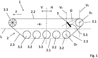
- Fig. 1 shows a side view and a highly schematic view of a track drive 1, as used in particular in military vehicles such as combat or infantry fighting vehicles, amphibious vehicles or other vehicles.
- the chain drive 1 has a circumferentially formed vehicle chain 2, which may be, for example, a chain made of steel with a plurality of stringed chain segments or a substantially consisting of a rubber material, continuously formed caterpillar, as this in the FIGS. 2 and 3 is shown.
- the chain 2 comes on the outside of the substrate in contact and extends with the inside around a substantially trapezoidal shaped drive space 4 with a plurality of rollers 3.1, 3.2, 3.3 around.
- Fig. 1 has the chain drive a number of freely rotatably mounted drive rollers 3.2, which are arranged in the region of a so-called lower strand 2.1 of the vehicle chain 2.
- the chain drive a number of freely rotatably mounted drive rollers 3.2, which are arranged in the region of a so-called lower strand 2.1 of the vehicle chain 2.
- At the substantially horizontally extending lower run 2 of the vehicle chain 2 close to both sides inclined transitional areas 2.3, over which the chain towards as pulleys trained drive rollers 3.1, 3.3 is performed.
- the upper run 2.2 of the vehicle chain 2 which also opposite the lower run 2.1 has a substantially horizontal orientation.
- the deflection roller 3.3 arranged in the front region V of the tracked vehicle is embodied as a drive pinion and is driven so far, whereas the rear deflection roller 3.1 is not designed to be driven. It is therefore a tracked vehicle with front wheel drive.
- the invention is equally applicable to rear-wheel drive tracked vehicles.
- the vehicle chain 2 moves under the freely rotatable drive rollers 3.2, passes through the rear transition area 2.3 up to the rear pulley 3.1.
- the recorded especially in the lower drive rollers 3.2 on the inside of the vehicle chain 2 dirt is thereby promoted in the direction of the rear guide pulley 3.1.
- the orientation of the vehicle chain 2 which points in the region of the upper run with the inside down, until this finally deflected again in the front pulley 3.3 and again on the front transition region 2.3 in the direction of the lower drive rollers 3.2 is moved.
- the throw-over area Ü is in Fig. 1 schematically represented and corresponds to a kind of throw parabolic opening, wherein dirt is ejected during fast travel in the upper region and slower travel in the lower region of the throw-over area Ü.
- the dirt deflector 5 in Fig. 1 also shown schematically.
- the arrangement of the dirt deflector 5 is chosen such that the funded along the throw-over area Ü dirt impinges on the Schmutzabweiser 5 and is directed laterally out of the drive compartment. Circulating the dirt, which would result from the dirt coming along the capping area Ü again on the top of the lower strand 2.1 of the vehicle chain 2, is thereby prevented in this way.
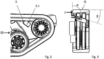
- the dirt deflector 5 is formed in the manner of a baffle element with an aligned in the direction of the capping area Ü baffle 5.1.
- the dirt deflector 5 is located in a position above the longitudinal center plane L of the chain drive 1 in the rear region H.
- the dirt deflector 5 is disposed near the upper run 2.2 of the vehicle chain 2.
- the dirt deflector 5 is viewed in the horizontal direction in the area between the rotation axis D 1 of the guide pulley designed as a rear roller 3.1 and the axis of rotation D 2 of the adjacent, freely rotatably mounted roller 3.2 in the area of the lower run 2.1, so that the dirt deflector in the area between two through the axes of rotation D 1 , D 2 of the rollers 3.1, 3.2 extending vertical planes V 1 , V 2 is located.
- the baffle 5.1 of the dirt deflector 5 is arranged obliquely inclined to drive outside. Like the illustration in Fig. 3 this can be seen, concludes the Baffle 5.1 an obtuse angle ⁇ with the inside I of the chain drive 1, which is about 100 ° in the embodiment.
- the baffle 5.1 with the top O of the drive space 4 includes an acute angle ⁇ , which is about 30 ° in the embodiment.
Landscapes
- Engineering & Computer Science (AREA)
- Chemical & Material Sciences (AREA)
- Combustion & Propulsion (AREA)
- Transportation (AREA)
- Mechanical Engineering (AREA)
- Devices For Conveying Motion By Means Of Endless Flexible Members (AREA)
- Platform Screen Doors And Railroad Systems (AREA)
- Vehicle Cleaning, Maintenance, Repair, Refitting, And Outriggers (AREA)
- Harvester Elements (AREA)
Abstract
Description
- Die vorliegende Erfindung betrifft ein Kettenlaufwerk, insbesondere für militärische Fahrzeuge, mit einer Fahrzeugkette, welche sich um einen mehrere Laufwerksrollen aufweisenden Laufwerkraum herum erstreckt. Einen weiteren Gegenstand bildet ein Fahrzeug mit einem solchen Kettenlaufwerk.
- Vor allem im militärischen Bereich werden aufgrund deren guter Fahreigenschaften auch in teilweise sehr unwegsamen Gelände häufig kettengetriebene Fahrzeuge eingesetzt, beispielsweise in Form von Kampfpanzern, Schützenpanzern, Amphibienfahrzeugen usw. Die Kettenfahrzeuge weisen hierzu in der Regel auf jeder Fahrzeugseite ein Kettenlaufwerk auf, welches zum Antrieb des Fahrzeugs über eine mit dem Fahrzeugantrieb gekoppelte Fahrzeugkette verfügt. Die Fahrzeugkette erstreckt sich dabei um einen Laufwerksraum herum, in welche verschiedene Laufwerksrollen des Kettenlaufwerks angeordnet sind, wie beispielsweise frei drehbare- oder angetriebene Laufwerksrollen, Umlenkrollen usw.
- Bei solchen Kettenfahrzeugen erfolgt insbesondere bei Geländefahrten auf schlammigem, sandigem oder steinigem Untergrund ein Schmutzeintrag in den zur Seite hin offenen Laufwerksraum. Dabei tritt der Schmutz von der Seite her in den Laufwerksraum ein und gelangt von oben her auf die Innenseite der Fahrzeugkette.
- Dies kann insbesondere bei aus einzelnen Kettensegmenten bestehenden Ketten, deren einzelne Kettenglieder nur sehr schmale Zwischenräume aufweisen, und insbesondere auch bei Bandketten, die bauartbedingt überhaupt keine Zwischenräume aufweisen sondern durchgängig ausgebildet sind, zu Problemen führen, da der in den Laufwerksraum eingetretene Schmutz nur schlecht wieder aus dem Laufwerksraum austreten kann. Im Fahrbetrieb können sich bei derartigen Fahrzeugketten in ungünstigen Situationen daher Zustände einstellen, in denen der in den Laufwerksraum eingebrachte Schmutz innerhalb des Laufwerksraums längere Zeit zirkuliert. Dies kann zu einem erhöhten Verschleiß und damit einer verminderten Lebensdauer der Laufwerkskomponenten und insbesondere der Laufrollen oder Ketten führen, insbesondere bei solchen Laufrollen oder Bandketten, die umfangsseitig mit einer Gummierung versehen sind.
- Aufgabe der vorliegenden Erfindung ist es daher, ein Kettenlaufwerk wie auch ein Fahrzeug mit einem Kettenlaufwerk anzugeben, bei welchen der schmutzbedingte Verschleiß reduziert ist.
- Zur Lösung dieser Aufgabe wird bei einem Kettenlaufwerk der eingangs genannten Art vorgeschlagen, dass dieses einen zumindest teilweise innerhalb des Laufwerksraums angeordneten Schmutzabweiser zum Austrag von Schmutz aus dem Laufwerkraum aufweist.
- Durch den innerhalb des Laufwerksraums angeordneten Schmutzabweiser kann der im Fahrbetrieb innerhalb des Laufwerks zirkulierende Schmutz aus dem Laufwerksraum ausgetragen werden. Der Schmutz zirkuliert nicht ständig innerhalb des Laufwerksraums, sondern wird beim Umlauf der Kette aus diesem ausgetragen. Es ergibt sich ein deutlich reduzierter Verschleiß und damit eine längere Lebensdauer der Laufwerkskomponenten.
- Eine vorteilhafte Ausgestaltung sieht vor, dass der Schmutzabweiser zumindest teilweise im Überwurfbereich einer hinteren, als Umlenkrolle ausgebildeten Laufwerksrolle angeordnet ist. Das Kettenlaufwerk weist verschiedene Arten von Laufwerksrollen auf, bei denen es sich um Laufrollen, Umlenkrollen, Stützrollen oder Antriebsritzel handeln kann. Im hinteren Bereich ist eine als Umlenkrolle ausgebildete Laufwerksrolle angeordnet, die als eine nach Art eines Antriebsritzels ausgebildete oder als frei drehbar gelagerte Umlenkrolle ausgebildet sein kann. Beim Umlaufen um die Umlenkrolle ändert sich die Ausrichtung der Ketteninnenseite, welche vor der Umlenkrolle mit deren Innenseite nach oben weist und nach Umlaufen über die Umlenkrolle mit deren Innenseite nach unten weist. Im Bereich der Umlenkrolle fällt daher der auf der Innenseite der Kette mitlaufende Schmutz von der Kette ab. Aufgrund der im Fahrbetrieb auftretenden Geschwindigkeiten und der damit auf den Schmutz wirkenden Beschleunigungen fällt dieser nicht senkrecht nach unten, sondern wird über die Umlenkrolle gefördert und dort in einem wurfparabelartigen Überwurfbereich abgeworfen. Vorteilhaft ist, wenn der Schmutzabweiser in diesem Überwurfbereich angeordnet ist und den Schmutz direkt aus dem Überwurfbereich aus dem Laufwerksraum austrägt. Ein längeres Zirkulieren des Schmutzes wird vermieden.
- Eine weitere vorteilhafte Ausgestaltung sieht vor, dass der Schmutzabweiser im hinteren Bereich des Laufwerksraums angeordnet ist. Denn entsprechend der Hauptfahrrichtung des Kettenlaufwerks fällt der auf der Innenseite der Fahrzeugkette mitbewegte Schmutz im hinteren Bereich des Kettenlaufwerks von der Fahrzeugkette ab und kann dort direkt aus dieser ausgetragen werden.
- Eine weitere vorteilhafte Ausgestaltung sieht vor, dass der Schmutzabweiser in horizontaler Richtung zwischen den Drehachsen der beiden hinteren Laufwerksrollen angeordnet ist. Die hinterste Laufwerksrolle wird üblicherweise gebildet von einer Umlenkrolle und die anderen Laufwerksrolle von einer gefederten, frei drehbar gelagerten Laufrolle. Durch die Anordnung des Schmutzabweisers im Bereich zwischen den Drehachsen der beiden Laufwerksrollen ergibt sich ein zuverlässiger, verschleißvermeidender Austrag von Schmutz aus dem Laufwerksraum.
- Eine weitere vorteilhafte Anordnung des Schmutzabweisers sieht vor, dass der Schmutzabweiser oberhalb einer horizontalen Längsmittelebene des Laufwerksraums angeordnet ist. Auch durch die solche Anordnung des Schmutzabweisers ergibt sich ein zuverlässiger, verschleißvermeidender Austrag von Schmutz aus dem Laufwerksraum.
- Eine in konstruktiver Hinsicht vorteilhafte Ausgestaltung sieht vor, dass der Schmutzabweiser als Prallelement, insbesondere als Prallblech, ausgebildet ist. Auf diese Weise kann der durch die im Fahrbetrieb auftretenden Beschleunigungen entlang einer Wurfparabel beschleunigte Schmutz durch Aufprallen auf den als Prallelement ausgebildeten Schmutzabweiser umgelenkt und aus dem Laufwerksraum gefördert werden. Das Prallelement kann in weiterer Ausgestaltung auch gummiert ausgebildet sein, wodurch sich im Fahrbetrieb eine geringere Geräuschentwicklung durch den auf dem Prallelement aufprallenden Schmutz ergibt.
- Vorteilhaft ist in diesem Zusammenhang, wenn der Schmutzabweiser eine Prallfläche aufweist, die derart ausgerichtet ist, dass auf dieser auftretender Schmutz seitlich aus dem Laufwerkraum herausgelenkt wird. In diesem Zusammenhang hat es sich ferner als konstruktiv vorteilhaft erwiesen, wenn die Prallfläche nach laufwerksaußen abschüssig geneigt ausgerichtet ist. Das Prallelement kann als eine Art Leitblech ausgebildet sein, entlang dessen Prallfläche der Schmutz aus dem Laufwerksraum herausgeleitet wird.
- Für einen zuverlässigen Austrag von Schmutz aus dem Laufwerksinnenraum hat es sich ferner als vorteilhaft erwiesen, wenn die Prallfläche mit der Innenseite des Laufwerksraumes einen stumpfen Winkel einschließt. Der stumpfe Winkel kann im Bereich von 95° bis 120°, vorteilhafterweise im Bereich von 100° bis 110°, liegen.
- Ebenso ist es für einen zuverlässigen Austrag von Schmutz aus dem Laufwerksinnenraum und damit einer verminderten Verschleißanfälligkeit von Vorteil, wenn die Prallfläche mit der Oberseite des Laufwerksraums einen spitzen Winkel einschließt. Dieser Winkel kann insbesondere im Bereich von 20° bis 60°, bevorzugt im Bereich von 25° bis 45°, und noch bevorzugter im Bereich von 30° bis 35° liegen.
- Bei einem Fahrzeug, welches ein Kettenlaufwerk mit einem oder mehreren der zuvor genannten Merkmale aufweist, ergeben sich die zuvor genannten Vorteile in analoger Weise.
- Weitere Einzelheiten und Vorteile eines erfindungsgemäßen Kettenlaufwerks sollen nachfolgend unter Zuhilfenahme der beigefügten Zeichnungen eines Ausführungsbeispiels erläutert werden. Darin zeigen:
- Fig. 1
- in stark schematisierter Form eine seitliche Ansicht eines Kettenlaufwerks,
- Fig. 2
- eine vergrößerte Ansicht des hinteren Bereichs eines Kettenlaufwerks und
- Fig. 3
- eine Ansicht des hinteren Teils des Kettenlaufwerks aus der in
Fig. 2 mit III gekennzeichneten Richtung. -
Fig. 1 zeigt in seitlicher und stark schematisierter Ansicht ein Kettenlaufwerk 1, wie dieses insbesondere bei militärischen Fahrzeugen wie etwa Kampf- oder Schützenpanzern, Amphibienfahrzeugen oder sonstigen Fahrzeugen verwendet wird. Das Kettenlaufwerk 1 weist eine umlaufend ausgebildete Fahrzeugkette 2 auf, bei welcher es sich beispielsweise um eine aus Stahl bestehende Kette mit mehreren aneinander gereihten Kettensegmenten oder eine im Wesentlichen aus einem Gummimaterial bestehende, durchgehend ausgebildete Gleiskette handeln kann, wie diese in denFig. 2 und 3 dargestellt ist. - Die Kette 2 gelangt auf deren Außenseite mit dem Untergrund in Kontakt und erstreckt sich mit deren Innenseite um einen im Wesentlichen trapezförmig ausgebildeten Laufwerksraum 4 mit mehreren Laufrollen 3.1, 3.2, 3.3 herum.
- Wie die Darstellung in
Fig. 1 erkennen lässt, weist das Kettenlaufwerk eine ganze Reihe frei drehbar gelagerter Laufwerksrollen 3.2 auf, welche im Bereich eines sogenannten Untertrums 2.1 der Fahrzeugkette 2 angeordnet sind. An den sich im Wesentlichen horizontal erstreckenden Untertrum 2 der Fahrzeugkette 2 schließen sich zu beiden Seiten geneigt verlaufende Übergangsbereiche 2.3 an, über welche die Kette hin zu als Umlenkrollen ausgebildeten Laufwerksrollen 3.1, 3.3 geführt ist. Im Bereich zwischen den Umlenkrollen 3.2, 3.3 befindet sich der Obertrum 2.2 der Fahrzeugkette 2, welcher dem Untertrum 2.1 gegenüberliegend ebenfalls eine im Wesentlichen horizontale Ausrichtung hat. - Beim Ausführungsbeispiel ist die im vorderen Bereich V des Kettenfahrzeugs angeordnete Umlenkrolle 3.3 als Antriebsritzel ausgeführt und ist insoweit angetrieben ausgebildet, wohingegen die hintere Umlenkrolle 3.1 nicht angetrieben ausgebildet ist. Es handelt sich daher um ein Kettenfahrzeug mit Frontantrieb. Die Erfindung ist in gleicher Weise jedoch auch bei heckgetriebenen Kettenfahrzeugen anwendbar.
- Beim Betrieb des Kettenlaufwerks 1 entlang der Hauptfahrrichtung F, welche der Vorwärtsfahrt des zugehörigen Kettenfahrzeugs entspricht, bewegt sich die Fahrzeugkette 2 unter den frei drehbaren Laufwerksrollen 3.2 hindurch, durchläuft den hinteren Übergangsbereich 2.3 bis hin zu der hinteren Umlenkrolle 3.1. Der vor allem im Bereich der unteren Laufwerksrollen 3.2 an der Innenseite der Fahrzeugkette 2 aufgenommene Schmutz wird dabei mit in Richtung der hinteren Umlenkrolle 3.1 gefördert. Nach Überlaufen der hinteren Umlenkrolle 3.1 ändert sich die Orientierung der Fahrzeugkette 2, welche im Bereich deren Obertrums mit deren Innenseite nach unten weist, bis diese im Bereich der vorderen Umlenkrolle 3.3 schließlich erneut umgelenkt und über den vorderen Übergangsbereich 2.3 erneut in Richtung der unteren Laufwerksrollen 3.2 bewegt wird.
- Der im Fahrbetrieb des Kettenlaufwerks 1 insbesondere bei Geländefahrt aufgenommene Schmutz, beispielsweise in Form von Steinen, Ästen, Laub und ähnlichem, wird über die Innenseiten der Fahrzeugkette 2 vor allem im Bereich deren Untertrums 2.1 aufgenommen, über den hinteren Übergangsbereich 2.3 in Richtung der hinteren Umlenkrolle 3.1 mitgenommen und dort nach erfolgter Umlenkung entlang eines Überwurfbereichs Ü ausgeworfen. Der Überwurfbereich Ü ist in
Fig. 1 schematisch dargestellt und entspricht einer Art Wurfparabelöffnung, wobei Schmutz bei schneller Fahrt im oberen Bereich und bei langsamerer Fahrt im unteren Bereich des Überwurfbereichs Ü ausgeworfen wird. - In dem Überwurfbereich Ü ist der Schmutzabweiser 5 in
Fig. 1 ebenfalls schematisch eingezeichnet. Die Anordnung des Schmutzabweisers 5 ist dabei derart gewählt, dass der entlang des Überwurfbereichs Ü geförderte Schmutz auf dem Schmutzabweiser 5 auftrifft und seitlich aus dem Laufwerksraum heraus gelenkt wird. Ein Zirkulieren des Schmutzes, welches sich dadurch ergeben würde, dass der Schmutz entlang des Überwurfbereichs Ü erneut auf die Oberseite des Untertrums 2.1 der Fahrzeugkette 2 gelangt, wird hierdurch auf diese Weise unterbunden. - Wie auch die Darstellungen in den
Fig. 2 und 3 dies erkennen lassen, ist der Schmutzabweiser 5 nach Art eines Prallelements mit einer in Richtung des Überwurfbereichs Ü ausgerichteten Prallfläche 5.1 ausgebildet. Der Schmutzabweiser 5 befindet sich dabei in einer Position oberhalb der Längsmittelebene L des Kettenlaufwerks 1 in dessen hinterem Bereich H. Der Schmutzabweiser 5 ist nahe des Obertrums 2.2 der Fahrzeugkette 2 angeordnet. Der Schmutzabweiser 5 befindet sich in horizontaler Richtung betrachtet im Bereich zwischen der Drehachse D1 der als Umlenkrolle ausgebildeten hinteren Laufrolle 3.1 und der Drehachse D2 der benachbarten, frei drehbar gelagerten Laufrolle 3.2 im Bereich des Untertrums 2.1, so dass sich der Schmutzabweiser im Bereich zwischen zwei durch die Drehachsen D1, D2 der Laufrollen 3.1, 3.2 verlaufenden Vertikalebenen V1, V2 befindet. - Um einen besonders günstigen Schmutzaustrag zu erreichen, ist die Prallfläche 5.1 des Schmutzabweisers 5 nach schräg laufwerksaußen geneigt angeordnet. Wie die Darstellung in
Fig. 3 dies erkennen lässt, schließt die Prallfläche 5.1 einen stumpfen Winkel α mit der Innenseite I des Kettenlaufwerls 1 ein, der beim Ausführungsbeispiel etwa 100° beträgt. Darüber hinaus schließt die Prallfläche 5.1 mit der Oberseite O des Laufwerkraums 4 einen spitzen Winkel β ein, der beim Ausführungsbeispiel bei etwa 30° liegt. - Aufgrund der Anordnung des Schmutzabweisers 5 nahe des oberen Kettentrums 2.2 im Bereich zwischen den beiden hinteren Laufwerksrollen 3.1, 3.2 ergibt sich ein zuverlässiger Austrag des über die Umlenkrolle 3.1 geförderten Schmutzes im laufenden Fahrbetrieb des Kettenlaufwerks 1. Der in das Kettenlaufwerk 1 eingetragene Schmutz zirkuliert nicht ewig innerhalb des Laufwerksraums 4, sondern wird beim Passieren der hinteren Laufwerksrolle 3.1 kontinuierlich aus dem Laufwerksraum herausbefördert. Hierdurch ergibt sich ein deutlich reduzierter Verschleiß, insbesondere an den Gummiflächen der Laufwerksrollen 3.1, 3.2, 3.3 sowie der Fahrzeugkette 2. Auch reduziert sich die Gefahr eines Ausspurens der Fahrzeugkette 2 durch die bei großem Schmutzeintrag verringerte Führung der Fahrzeugkette 2 auf den Laufwerksrollen 3.1, 3.2, 3.3.
-
- 1
- Kettenlaufwerk
- 2
- Fahrzeugkette
- 2.1
- Untertrum
- 2.2
- Obertrum
- 2.3
- Übergangsbereich
- 3.1
- Laufrolle, Umlenkrolle
- 3.2
- Laufrolle, frei drehend
- 3.3
- Laufrolle, Antriebsritzel
- 4
- Laufwerksraum
- 5
- Schmutzabweiser
- 5.1
- Prallfläche
- V
- vorderer Bereich
- H
- hinterer Bereich
- D1
- Drehachse
- D2
- Drehachse
- V1
- vertikale Ebene
- V2
- vertikale Ebene
- L
- Längsmittelebene
- Ü
- Überwurfbereich
- F
- Hauptfahrtrichtung
- I
- Innenseite
- O
- Oberseite
Claims (11)
- Kettenlaufwerk, insbesondere für militärische Fahrzeuge, mit einer Fahrzeugkette (2), welche sich um einen mehrere Laufwerksrollen (3.1, 3.2, 3.3) aufweisenden Laufwerksraum (4) herum erstreckt, gekennzeichnet durch
einen zumindest teilweise innerhalb des Laufwerksraums (4) angeordneten Schmutzabweiser(5) zum Austrag von Schmutz aus dem Laufwerksraum (4). - Kettenlaufwerk nach Anspruch 1, dadurch gekennzeichnet, dass der Schmutzabweiser (5) zumindest teilweise im Überwurfbereich (Ü) einer hinteren, als Umlenkrolle ausgebildeten Laufwerksrolle (3.1) angeordnet ist.
- Kettenlaufwerk nach Anspruch 1 oder Anspruch 2, dadurch gekennzeichnet, dass der Schmutzabweiser (5) im hinteren Bereich (H) des Laufwerkraums (4) angeordnet ist.
- Kettenlaufwerk nach einem der vorhergehenden Ansprüche, dadurch gekennzeichnet, dass der Schmutzabweiser (5) in horizontaler Richtung zwischen den Drehachsen (D1, D2) der beiden hinteren Laufwerksrollen (3) angeordnet ist.
- Kettenlaufwerk nach einem der vorhergehenden Ansprüche, dadurch gekennzeichnet, dass der Schmutzabweiser (5) oberhalb einer horizontalen Längsmittelebene (L) des Laufwerkraums (4) angeordnet ist.
- Kettenlaufwerk nach einem der vorhergehenden Ansprüche, dadurch gekennzeichnet, dass der Schmutzabweiser (5) als Prallelement, insbesondere als Prallblech, ausgebildet ist.
- Kettenlaufwerk nach einem der vorhergehenden Ansprüche, dadurch gekennzeichnet, dass der Schmutzabweiser (5) eine Prallfläche (5.1) aufweist, die derart ausgerichtet ist, dass auf dieser auftreffender Schmutz seitlich aus dem Laufwerksraum (4) heraus gelenkt wird.
- Kettenlaufwerk nach Anspruch 7, dadurch gekennzeichnet, dass die Prallfläche (5.1) nach laufwerksaußen abschüssig geneigt ausgerichtet ist.
- Kettenlaufwerk nach einem der Ansprüche 7 oder 8, dadurch gekennzeichnet, dass die Prallfläche (5.1) mit der Innenseite (I) des Laufwerksraums (4) einen stumpfen Winkel (α) einschließt.
- Kettenlaufwerk nach einem der Ansprüche 7 bis 9, dadurch gekennzeichnet, dass die Prallfläche (5.1) mit der Oberseite (O) des Laufwerksraums (4) einen spitzen Winkel (β) einschließt.
- Fahrzeug, insbesondere militärisches Fahrzeug, mit mindestens einem Kettenlaufwerk (1) nach einem der Ansprüche 1 bis 10.
Applications Claiming Priority (1)
| Application Number | Priority Date | Filing Date | Title |
|---|---|---|---|
| DE102016102715.4A DE102016102715A1 (de) | 2016-02-16 | 2016-02-16 | Kettenlaufwerk für militärische Fahrzeuge |
Publications (3)
| Publication Number | Publication Date |
|---|---|
| EP3208181A1 true EP3208181A1 (de) | 2017-08-23 |
| EP3208181B1 EP3208181B1 (de) | 2021-03-24 |
| EP3208181B2 EP3208181B2 (de) | 2024-09-18 |
Family
ID=58043899
Family Applications (1)
| Application Number | Title | Priority Date | Filing Date |
|---|---|---|---|
| EP17155695.4A Active EP3208181B2 (de) | 2016-02-16 | 2017-02-10 | Kettenlaufwerk für militärische fahrzeuge |
Country Status (3)
| Country | Link |
|---|---|
| EP (1) | EP3208181B2 (de) |
| DE (1) | DE102016102715A1 (de) |
| ES (1) | ES2875873T5 (de) |
Cited By (2)
| Publication number | Priority date | Publication date | Assignee | Title |
|---|---|---|---|---|
| CN110406450A (zh) * | 2019-09-09 | 2019-11-05 | 山东吉鲁汽车改装有限公司 | 一种链条防污装置及包含它的车辆 |
| WO2020013751A1 (en) * | 2018-07-09 | 2020-01-16 | BAE Systems Hägglunds Aktiebolag | Deflector arrangement for a tracked vehicle |
Citations (5)
| Publication number | Priority date | Publication date | Assignee | Title |
|---|---|---|---|---|
| US2560307A (en) * | 1946-04-25 | 1951-07-10 | Goodrich Co B F | Band and pulley structure |
| US20050275287A1 (en) * | 2004-06-09 | 2005-12-15 | Remi Breton | Snow and debris deflector for a track system |
| US20070170777A1 (en) * | 2006-01-23 | 2007-07-26 | Plante Sean M | Tracked suspension beam assembly |
| US20100051358A1 (en) * | 2008-08-27 | 2010-03-04 | Kubota Corporation | Crawler Traveling Apparatus |
| DE202011050456U1 (de) * | 2011-06-15 | 2011-07-15 | Franz-Alfred Haas | Tandembogieachse |
Family Cites Families (14)
| Publication number | Priority date | Publication date | Assignee | Title |
|---|---|---|---|---|
| US2652289A (en) | 1950-04-14 | 1953-09-15 | Bekker Mieczyslaw Gregory | Tracked gear with cushioned lubricated leakproof skid suspension |
| US2637603A (en) | 1951-12-07 | 1953-05-05 | Goodman Mfg Co | Muck stripper for endless track treads |
| GB850690A (en) | 1956-09-21 | 1960-10-05 | Frederick Gilbert Mitchell | Improvements in or relating to conveyor systems |
| US2843431A (en) | 1956-12-28 | 1958-07-15 | John M Beaufort | Hydraulic track tensioning device |
| US2967075A (en) | 1957-07-31 | 1961-01-03 | Burke Wilford E | Land vehicle wheel |
| DE1932987U (de) * | 1965-11-17 | 1966-02-17 | Diehl K G | Vorrichtung zum verhindern von schnee-, lehm- oder schlammansaetzen an antriebstrommeln von gleiskettenfahrzeugen. |
| US3976337A (en) | 1975-03-17 | 1976-08-24 | Caterpillar Tractor Co. | Striker bar for cleaning the tracks of track-type vehicles |
| US4134622A (en) | 1977-01-28 | 1979-01-16 | Caterpillar Tractor Co. | Scraping apparatus for track-type vehicles |
| US4531787A (en) | 1980-12-02 | 1985-07-30 | Caterpillar Tractor Co. | Debris deflector for endless track system |
| US4553790A (en) | 1982-01-29 | 1985-11-19 | Caterpillar Tractor Co. | Flexible dirt guard with back-up plate for track-type vehicle |
| US4830439A (en) | 1987-10-07 | 1989-05-16 | The United States Of America As Represented By The Secretary Of The Army | Separable scraper bar attachment for track-type vehicles |
| US5725292A (en) | 1996-06-25 | 1998-03-10 | Caterpillar Inc. | Scraping apparatus for a track idler |
| US7434897B2 (en) | 2001-03-22 | 2008-10-14 | Thomas Dom | Endless track constructed from vehicle tire |
| US9352793B2 (en) | 2013-03-12 | 2016-05-31 | Caterpillar Global Mining Llc | Slide shoe for undercarriage frame assembly |
-
2016
- 2016-02-16 DE DE102016102715.4A patent/DE102016102715A1/de not_active Withdrawn
-
2017
- 2017-02-10 EP EP17155695.4A patent/EP3208181B2/de active Active
- 2017-02-10 ES ES17155695T patent/ES2875873T5/es active Active
Patent Citations (5)
| Publication number | Priority date | Publication date | Assignee | Title |
|---|---|---|---|---|
| US2560307A (en) * | 1946-04-25 | 1951-07-10 | Goodrich Co B F | Band and pulley structure |
| US20050275287A1 (en) * | 2004-06-09 | 2005-12-15 | Remi Breton | Snow and debris deflector for a track system |
| US20070170777A1 (en) * | 2006-01-23 | 2007-07-26 | Plante Sean M | Tracked suspension beam assembly |
| US20100051358A1 (en) * | 2008-08-27 | 2010-03-04 | Kubota Corporation | Crawler Traveling Apparatus |
| DE202011050456U1 (de) * | 2011-06-15 | 2011-07-15 | Franz-Alfred Haas | Tandembogieachse |
Cited By (3)
| Publication number | Priority date | Publication date | Assignee | Title |
|---|---|---|---|---|
| WO2020013751A1 (en) * | 2018-07-09 | 2020-01-16 | BAE Systems Hägglunds Aktiebolag | Deflector arrangement for a tracked vehicle |
| US11834114B2 (en) | 2018-07-09 | 2023-12-05 | BAE Systems Hägglunds Aktiebolag | Deflector arrangement for a tracked vehicle |
| CN110406450A (zh) * | 2019-09-09 | 2019-11-05 | 山东吉鲁汽车改装有限公司 | 一种链条防污装置及包含它的车辆 |
Also Published As
| Publication number | Publication date |
|---|---|
| DE102016102715A1 (de) | 2017-08-17 |
| EP3208181B2 (de) | 2024-09-18 |
| ES2875873T3 (es) | 2021-11-11 |
| ES2875873T5 (en) | 2025-02-10 |
| EP3208181B1 (de) | 2021-03-24 |
Similar Documents
| Publication | Publication Date | Title |
|---|---|---|
| EP0212174B1 (de) | Kartoffelerntemaschine | |
| EP0261097A2 (de) | Vorrichtung zur Räumung von Verkehrsflächen von Schnee, Schneematsch, Wasser, Schmutz od.dgl. | |
| EP2835471B2 (de) | Selbstfahrende Straßenfräsmaschine, sowie Verfahren zum Abfräsen und Abtransportieren eines abgefrästen Materialstroms | |
| DE602004000974T2 (de) | Muldenbandförderer | |
| DE102015225417A1 (de) | Fahrzeugluftreifen | |
| EP3339224B1 (de) | Kanal- oder/und strassenreinigungsvorrichtung | |
| DE102018108877A1 (de) | Siebbandeinheit | |
| EP3419920B1 (de) | Förderanlage zum fördern von fördergut | |
| DE3016596C2 (de) | ||
| DE1903566A1 (de) | Raupenfahrzeug | |
| EP3208181B1 (de) | Kettenlaufwerk für militärische fahrzeuge | |
| DE102015118240A1 (de) | Strahlanlage zum Strahlen von Werkstücken | |
| DE2051995B2 (de) | Steilförderer | |
| DE102011118791B4 (de) | Förderband zur Verwendung in einer Fräsvorrichtung und Fräsvorrichtung mit einem solchen Förderband | |
| DE102019210060A1 (de) | Band- oder riemenartiges Förderelement | |
| DE2752012A1 (de) | Dreschmaschine | |
| EP3390108B1 (de) | Fahrzeugluftreifen | |
| EP0403505B1 (de) | Vorrichtung zum schutz eines fahrzeugrads vor aquaplaning | |
| DE3404847A1 (de) | Schneeschleuder | |
| DE4116467A1 (de) | Stetigfoerderndes ladegeraet fuer schuettgueter | |
| DE102015215787A1 (de) | Einrichtung zum Leiten eines Materialstroms | |
| DE102017101226A1 (de) | Vorrichtung für die Abdichtung zwischen Windkästen unterschiedlichen Drucks in Wanderrostanlagen | |
| DE102015106096A1 (de) | Fördersystem für Schüttgüter | |
| DE102008029797B4 (de) | Tunnelbogen-Steckmaschine | |
| CH635387A5 (de) | Schneeraeumeinrichtung mit einem schleuderrad und einer diesem in raeumrichtung vorgeordneten schneid- und foerdervorrichtung. |
Legal Events
| Date | Code | Title | Description |
|---|---|---|---|
| PUAI | Public reference made under article 153(3) epc to a published international application that has entered the european phase |
Free format text: ORIGINAL CODE: 0009012 |
|
| STAA | Information on the status of an ep patent application or granted ep patent |
Free format text: STATUS: THE APPLICATION HAS BEEN PUBLISHED |
|
| AK | Designated contracting states |
Kind code of ref document: A1 Designated state(s): AL AT BE BG CH CY CZ DE DK EE ES FI FR GB GR HR HU IE IS IT LI LT LU LV MC MK MT NL NO PL PT RO RS SE SI SK SM TR |
|
| AX | Request for extension of the european patent |
Extension state: BA ME |
|
| STAA | Information on the status of an ep patent application or granted ep patent |
Free format text: STATUS: REQUEST FOR EXAMINATION WAS MADE |
|
| 17P | Request for examination filed |
Effective date: 20180223 |
|
| RBV | Designated contracting states (corrected) |
Designated state(s): AL AT BE BG CH CY CZ DE DK EE ES FI FR GB GR HR HU IE IS IT LI LT LU LV MC MK MT NL NO PL PT RO RS SE SI SK SM TR |
|
| STAA | Information on the status of an ep patent application or granted ep patent |
Free format text: STATUS: EXAMINATION IS IN PROGRESS |
|
| 17Q | First examination report despatched |
Effective date: 20190906 |
|
| GRAP | Despatch of communication of intention to grant a patent |
Free format text: ORIGINAL CODE: EPIDOSNIGR1 |
|
| STAA | Information on the status of an ep patent application or granted ep patent |
Free format text: STATUS: GRANT OF PATENT IS INTENDED |
|
| INTG | Intention to grant announced |
Effective date: 20201022 |
|
| RIC1 | Information provided on ipc code assigned before grant |
Ipc: B62D 55/088 20060101AFI20201012BHEP |
|
| GRAS | Grant fee paid |
Free format text: ORIGINAL CODE: EPIDOSNIGR3 |
|
| GRAA | (expected) grant |
Free format text: ORIGINAL CODE: 0009210 |
|
| STAA | Information on the status of an ep patent application or granted ep patent |
Free format text: STATUS: THE PATENT HAS BEEN GRANTED |
|
| AK | Designated contracting states |
Kind code of ref document: B1 Designated state(s): AL AT BE BG CH CY CZ DE DK EE ES FI FR GB GR HR HU IE IS IT LI LT LU LV MC MK MT NL NO PL PT RO RS SE SI SK SM TR |
|
| REG | Reference to a national code |
Ref country code: GB Ref legal event code: FG4D Free format text: NOT ENGLISH |
|
| REG | Reference to a national code |
Ref country code: CH Ref legal event code: EP |
|
| REG | Reference to a national code |
Ref country code: DE Ref legal event code: R096 Ref document number: 502017009776 Country of ref document: DE |
|
| REG | Reference to a national code |
Ref country code: IE Ref legal event code: FG4D Free format text: LANGUAGE OF EP DOCUMENT: GERMAN |
|
| REG | Reference to a national code |
Ref country code: AT Ref legal event code: REF Ref document number: 1374221 Country of ref document: AT Kind code of ref document: T Effective date: 20210415 |
|
| REG | Reference to a national code |
Ref country code: CH Ref legal event code: NV Representative=s name: VALIPAT S.A. C/O BOVARD SA NEUCHATEL, CH |
|
| REG | Reference to a national code |
Ref country code: SE Ref legal event code: TRGR |
|
| REG | Reference to a national code |
Ref country code: LT Ref legal event code: MG9D |
|
| PG25 | Lapsed in a contracting state [announced via postgrant information from national office to epo] |
Ref country code: HR Free format text: LAPSE BECAUSE OF FAILURE TO SUBMIT A TRANSLATION OF THE DESCRIPTION OR TO PAY THE FEE WITHIN THE PRESCRIBED TIME-LIMIT Effective date: 20210324 Ref country code: FI Free format text: LAPSE BECAUSE OF FAILURE TO SUBMIT A TRANSLATION OF THE DESCRIPTION OR TO PAY THE FEE WITHIN THE PRESCRIBED TIME-LIMIT Effective date: 20210324 Ref country code: GR Free format text: LAPSE BECAUSE OF FAILURE TO SUBMIT A TRANSLATION OF THE DESCRIPTION OR TO PAY THE FEE WITHIN THE PRESCRIBED TIME-LIMIT Effective date: 20210625 Ref country code: BG Free format text: LAPSE BECAUSE OF FAILURE TO SUBMIT A TRANSLATION OF THE DESCRIPTION OR TO PAY THE FEE WITHIN THE PRESCRIBED TIME-LIMIT Effective date: 20210624 |
|
| REG | Reference to a national code |
Ref country code: NO Ref legal event code: T2 Effective date: 20210324 |
|
| PG25 | Lapsed in a contracting state [announced via postgrant information from national office to epo] |
Ref country code: RS Free format text: LAPSE BECAUSE OF FAILURE TO SUBMIT A TRANSLATION OF THE DESCRIPTION OR TO PAY THE FEE WITHIN THE PRESCRIBED TIME-LIMIT Effective date: 20210324 Ref country code: LV Free format text: LAPSE BECAUSE OF FAILURE TO SUBMIT A TRANSLATION OF THE DESCRIPTION OR TO PAY THE FEE WITHIN THE PRESCRIBED TIME-LIMIT Effective date: 20210324 |
|
| REG | Reference to a national code |
Ref country code: NL Ref legal event code: MP Effective date: 20210324 |
|
| PG25 | Lapsed in a contracting state [announced via postgrant information from national office to epo] |
Ref country code: NL Free format text: LAPSE BECAUSE OF FAILURE TO SUBMIT A TRANSLATION OF THE DESCRIPTION OR TO PAY THE FEE WITHIN THE PRESCRIBED TIME-LIMIT Effective date: 20210324 |
|
| PG25 | Lapsed in a contracting state [announced via postgrant information from national office to epo] |
Ref country code: CZ Free format text: LAPSE BECAUSE OF FAILURE TO SUBMIT A TRANSLATION OF THE DESCRIPTION OR TO PAY THE FEE WITHIN THE PRESCRIBED TIME-LIMIT Effective date: 20210324 Ref country code: EE Free format text: LAPSE BECAUSE OF FAILURE TO SUBMIT A TRANSLATION OF THE DESCRIPTION OR TO PAY THE FEE WITHIN THE PRESCRIBED TIME-LIMIT Effective date: 20210324 Ref country code: LT Free format text: LAPSE BECAUSE OF FAILURE TO SUBMIT A TRANSLATION OF THE DESCRIPTION OR TO PAY THE FEE WITHIN THE PRESCRIBED TIME-LIMIT Effective date: 20210324 Ref country code: SM Free format text: LAPSE BECAUSE OF FAILURE TO SUBMIT A TRANSLATION OF THE DESCRIPTION OR TO PAY THE FEE WITHIN THE PRESCRIBED TIME-LIMIT Effective date: 20210324 |
|
| REG | Reference to a national code |
Ref country code: DE Ref legal event code: R026 Ref document number: 502017009776 Country of ref document: DE |
|
| PLBI | Opposition filed |
Free format text: ORIGINAL CODE: 0009260 |
|
| REG | Reference to a national code |
Ref country code: ES Ref legal event code: FG2A Ref document number: 2875873 Country of ref document: ES Kind code of ref document: T3 Effective date: 20211111 |
|
| PG25 | Lapsed in a contracting state [announced via postgrant information from national office to epo] |
Ref country code: SK Free format text: LAPSE BECAUSE OF FAILURE TO SUBMIT A TRANSLATION OF THE DESCRIPTION OR TO PAY THE FEE WITHIN THE PRESCRIBED TIME-LIMIT Effective date: 20210324 Ref country code: RO Free format text: LAPSE BECAUSE OF FAILURE TO SUBMIT A TRANSLATION OF THE DESCRIPTION OR TO PAY THE FEE WITHIN THE PRESCRIBED TIME-LIMIT Effective date: 20210324 Ref country code: PL Free format text: LAPSE BECAUSE OF FAILURE TO SUBMIT A TRANSLATION OF THE DESCRIPTION OR TO PAY THE FEE WITHIN THE PRESCRIBED TIME-LIMIT Effective date: 20210324 Ref country code: PT Free format text: LAPSE BECAUSE OF FAILURE TO SUBMIT A TRANSLATION OF THE DESCRIPTION OR TO PAY THE FEE WITHIN THE PRESCRIBED TIME-LIMIT Effective date: 20210726 Ref country code: IS Free format text: LAPSE BECAUSE OF FAILURE TO SUBMIT A TRANSLATION OF THE DESCRIPTION OR TO PAY THE FEE WITHIN THE PRESCRIBED TIME-LIMIT Effective date: 20210724 |
|
| 26 | Opposition filed |
Opponent name: RHEINMETALL LANDSYSTEME GMBH Effective date: 20211104 |
|
| PLAX | Notice of opposition and request to file observation + time limit sent |
Free format text: ORIGINAL CODE: EPIDOSNOBS2 |
|
| PG25 | Lapsed in a contracting state [announced via postgrant information from national office to epo] |
Ref country code: DK Free format text: LAPSE BECAUSE OF FAILURE TO SUBMIT A TRANSLATION OF THE DESCRIPTION OR TO PAY THE FEE WITHIN THE PRESCRIBED TIME-LIMIT Effective date: 20210324 Ref country code: AL Free format text: LAPSE BECAUSE OF FAILURE TO SUBMIT A TRANSLATION OF THE DESCRIPTION OR TO PAY THE FEE WITHIN THE PRESCRIBED TIME-LIMIT Effective date: 20210324 |
|
| PG25 | Lapsed in a contracting state [announced via postgrant information from national office to epo] |
Ref country code: SI Free format text: LAPSE BECAUSE OF FAILURE TO SUBMIT A TRANSLATION OF THE DESCRIPTION OR TO PAY THE FEE WITHIN THE PRESCRIBED TIME-LIMIT Effective date: 20210324 |
|
| PLBB | Reply of patent proprietor to notice(s) of opposition received |
Free format text: ORIGINAL CODE: EPIDOSNOBS3 |
|
| PG25 | Lapsed in a contracting state [announced via postgrant information from national office to epo] |
Ref country code: IS Free format text: LAPSE BECAUSE OF FAILURE TO SUBMIT A TRANSLATION OF THE DESCRIPTION OR TO PAY THE FEE WITHIN THE PRESCRIBED TIME-LIMIT Effective date: 20210724 |
|
| PG25 | Lapsed in a contracting state [announced via postgrant information from national office to epo] |
Ref country code: MC Free format text: LAPSE BECAUSE OF FAILURE TO SUBMIT A TRANSLATION OF THE DESCRIPTION OR TO PAY THE FEE WITHIN THE PRESCRIBED TIME-LIMIT Effective date: 20210324 |
|
| REG | Reference to a national code |
Ref country code: BE Ref legal event code: MM Effective date: 20220228 |
|
| PG25 | Lapsed in a contracting state [announced via postgrant information from national office to epo] |
Ref country code: LU Free format text: LAPSE BECAUSE OF NON-PAYMENT OF DUE FEES Effective date: 20220210 |
|
| PLAB | Opposition data, opponent's data or that of the opponent's representative modified |
Free format text: ORIGINAL CODE: 0009299OPPO |
|
| PG25 | Lapsed in a contracting state [announced via postgrant information from national office to epo] |
Ref country code: IE Free format text: LAPSE BECAUSE OF NON-PAYMENT OF DUE FEES Effective date: 20220210 |
|
| R26 | Opposition filed (corrected) |
Opponent name: RHEINMETALL LANDSYSTEME GMBH Effective date: 20211104 |
|
| PG25 | Lapsed in a contracting state [announced via postgrant information from national office to epo] |
Ref country code: BE Free format text: LAPSE BECAUSE OF NON-PAYMENT OF DUE FEES Effective date: 20220228 |
|
| REG | Reference to a national code |
Ref country code: AT Ref legal event code: MM01 Ref document number: 1374221 Country of ref document: AT Kind code of ref document: T Effective date: 20220210 |
|
| PG25 | Lapsed in a contracting state [announced via postgrant information from national office to epo] |
Ref country code: AT Free format text: LAPSE BECAUSE OF NON-PAYMENT OF DUE FEES Effective date: 20220210 |
|
| PLAB | Opposition data, opponent's data or that of the opponent's representative modified |
Free format text: ORIGINAL CODE: 0009299OPPO |
|
| P01 | Opt-out of the competence of the unified patent court (upc) registered |
Effective date: 20230527 |
|
| PLAB | Opposition data, opponent's data or that of the opponent's representative modified |
Free format text: ORIGINAL CODE: 0009299OPPO |
|
| R26 | Opposition filed (corrected) |
Opponent name: RHEINMETALL LANDSYSTEME GMBH Effective date: 20211104 |
|
| R26 | Opposition filed (corrected) |
Opponent name: RHEINMETALL LANDSYSTEME GMBH Effective date: 20211104 |
|
| PG25 | Lapsed in a contracting state [announced via postgrant information from national office to epo] |
Ref country code: HU Free format text: LAPSE BECAUSE OF FAILURE TO SUBMIT A TRANSLATION OF THE DESCRIPTION OR TO PAY THE FEE WITHIN THE PRESCRIBED TIME-LIMIT; INVALID AB INITIO Effective date: 20170210 |
|
| PG25 | Lapsed in a contracting state [announced via postgrant information from national office to epo] |
Ref country code: MK Free format text: LAPSE BECAUSE OF FAILURE TO SUBMIT A TRANSLATION OF THE DESCRIPTION OR TO PAY THE FEE WITHIN THE PRESCRIBED TIME-LIMIT Effective date: 20210324 Ref country code: CY Free format text: LAPSE BECAUSE OF FAILURE TO SUBMIT A TRANSLATION OF THE DESCRIPTION OR TO PAY THE FEE WITHIN THE PRESCRIBED TIME-LIMIT Effective date: 20210324 |
|
| PUAH | Patent maintained in amended form |
Free format text: ORIGINAL CODE: 0009272 |
|
| STAA | Information on the status of an ep patent application or granted ep patent |
Free format text: STATUS: PATENT MAINTAINED AS AMENDED |
|
| REG | Reference to a national code |
Ref country code: DE Ref legal event code: R081 Ref document number: 502017009776 Country of ref document: DE Owner name: KNDS DEUTSCHLAND GMBH & CO. KG, DE Free format text: FORMER OWNER: KRAUSS-MAFFEI WEGMANN GMBH & CO. KG, 80997 MUENCHEN, DE |
|
| RAP4 | Party data changed (patent owner data changed or rights of a patent transferred) |
Owner name: KNDS DEUTSCHLAND GMBH & CO. KG |
|
| 27A | Patent maintained in amended form |
Effective date: 20240918 |
|
| AK | Designated contracting states |
Kind code of ref document: B2 Designated state(s): AL AT BE BG CH CY CZ DE DK EE ES FI FR GB GR HR HU IE IS IT LI LT LU LV MC MK MT NL NO PL PT RO RS SE SI SK SM TR |
|
| REG | Reference to a national code |
Ref country code: DE Ref legal event code: R102 Ref document number: 502017009776 Country of ref document: DE |
|
| PG25 | Lapsed in a contracting state [announced via postgrant information from national office to epo] |
Ref country code: MT Free format text: LAPSE BECAUSE OF FAILURE TO SUBMIT A TRANSLATION OF THE DESCRIPTION OR TO PAY THE FEE WITHIN THE PRESCRIBED TIME-LIMIT Effective date: 20210324 |
|
| REG | Reference to a national code |
Ref country code: SE Ref legal event code: RPEO |
|
| REG | Reference to a national code |
Ref country code: ES Ref legal event code: DC2A Ref document number: 2875873 Country of ref document: ES Kind code of ref document: T5 Effective date: 20250210 |
|
| REG | Reference to a national code |
Ref country code: CH Ref legal event code: U11 Free format text: ST27 STATUS EVENT CODE: U-0-0-U10-U11 (AS PROVIDED BY THE NATIONAL OFFICE) Effective date: 20260301 |
|
| PGFP | Annual fee paid to national office [announced via postgrant information from national office to epo] |
Ref country code: SE Payment date: 20260218 Year of fee payment: 10 |
|
| PGFP | Annual fee paid to national office [announced via postgrant information from national office to epo] |
Ref country code: GB Payment date: 20260219 Year of fee payment: 10 |
|
| PGFP | Annual fee paid to national office [announced via postgrant information from national office to epo] |
Ref country code: ES Payment date: 20260319 Year of fee payment: 10 |
|
| PGFP | Annual fee paid to national office [announced via postgrant information from national office to epo] |
Ref country code: DE Payment date: 20260228 Year of fee payment: 10 Ref country code: NO Payment date: 20260217 Year of fee payment: 10 |
|
| PGFP | Annual fee paid to national office [announced via postgrant information from national office to epo] |
Ref country code: IT Payment date: 20260227 Year of fee payment: 10 |
|
| PGFP | Annual fee paid to national office [announced via postgrant information from national office to epo] |
Ref country code: FR Payment date: 20260223 Year of fee payment: 10 |
|
| PGFP | Annual fee paid to national office [announced via postgrant information from national office to epo] |
Ref country code: TR Payment date: 20260205 Year of fee payment: 10 |
|
| PGFP | Annual fee paid to national office [announced via postgrant information from national office to epo] |
Ref country code: CH Payment date: 20260301 Year of fee payment: 10 |