EP3208186A1 - Dispositif de commande de direction de bateau - Google Patents
Dispositif de commande de direction de bateau Download PDFInfo
- Publication number
- EP3208186A1 EP3208186A1 EP17156818.1A EP17156818A EP3208186A1 EP 3208186 A1 EP3208186 A1 EP 3208186A1 EP 17156818 A EP17156818 A EP 17156818A EP 3208186 A1 EP3208186 A1 EP 3208186A1
- Authority
- EP
- European Patent Office
- Prior art keywords
- case
- tilt
- drive shaft
- bridge
- assembly
- Prior art date
- Legal status (The legal status is an assumption and is not a legal conclusion. Google has not performed a legal analysis and makes no representation as to the accuracy of the status listed.)
- Granted
Links
Images


Classifications
-
- B—PERFORMING OPERATIONS; TRANSPORTING
- B63—SHIPS OR OTHER WATERBORNE VESSELS; RELATED EQUIPMENT
- B63H—MARINE PROPULSION OR STEERING
- B63H20/00—Outboard propulsion units, e.g. outboard motors or Z-drives; Arrangements thereof on vessels
- B63H20/08—Means enabling movement of the position of the propulsion element, e.g. for trim, tilt or steering; Control of trim or tilt
- B63H20/12—Means enabling steering
-
- B—PERFORMING OPERATIONS; TRANSPORTING
- B63—SHIPS OR OTHER WATERBORNE VESSELS; RELATED EQUIPMENT
- B63H—MARINE PROPULSION OR STEERING
- B63H20/00—Outboard propulsion units, e.g. outboard motors or Z-drives; Arrangements thereof on vessels
- B63H20/08—Means enabling movement of the position of the propulsion element, e.g. for trim, tilt or steering; Control of trim or tilt
- B63H20/10—Means enabling trim or tilt, or lifting of the propulsion element when an obstruction is hit; Control of trim or tilt
-
- B—PERFORMING OPERATIONS; TRANSPORTING
- B63—SHIPS OR OTHER WATERBORNE VESSELS; RELATED EQUIPMENT
- B63H—MARINE PROPULSION OR STEERING
- B63H25/00—Steering; Slowing-down otherwise than by use of propulsive elements; Dynamic anchoring, i.e. positioning vessels by means of main or auxiliary propulsive elements
- B63H25/02—Initiating means for steering, for slowing down, otherwise than by use of propulsive elements, or for dynamic anchoring
-
- B—PERFORMING OPERATIONS; TRANSPORTING
- B63—SHIPS OR OTHER WATERBORNE VESSELS; RELATED EQUIPMENT
- B63H—MARINE PROPULSION OR STEERING
- B63H25/00—Steering; Slowing-down otherwise than by use of propulsive elements; Dynamic anchoring, i.e. positioning vessels by means of main or auxiliary propulsive elements
- B63H25/06—Steering by rudders
-
- B—PERFORMING OPERATIONS; TRANSPORTING
- B63—SHIPS OR OTHER WATERBORNE VESSELS; RELATED EQUIPMENT
- B63H—MARINE PROPULSION OR STEERING
- B63H25/00—Steering; Slowing-down otherwise than by use of propulsive elements; Dynamic anchoring, i.e. positioning vessels by means of main or auxiliary propulsive elements
- B63H25/02—Initiating means for steering, for slowing down, otherwise than by use of propulsive elements, or for dynamic anchoring
- B63H2025/022—Steering wheels; Posts for steering wheels
Definitions
- the present invention relates to the field of steering control systems for boats, watercrafts or the like.
- These systems comprise a steering member, such as for example a steering wheel or helm, whose rotation causes the corresponding rotation of a drive shaft of a control pulse or signal generating device which is typically housed in a case from which said drive shaft protrudes and that by means of a transmission circuit, transmits the generated pulses or signals corresponding to the rotational motion of the shaft to an actuator, associated with the motor and/or rudder or other units that change the direction of a watercraft.
- a steering member such as for example a steering wheel or helm
- a control pulse or signal generating device which is typically housed in a case from which said drive shaft protrudes and that by means of a transmission circuit, transmits the generated pulses or signals corresponding to the rotational motion of the shaft to an actuator, associated with the motor and/or rudder or other units that change the direction of a watercraft.
- the rotation of the drive shaft causes a displacement of a pressurized fluid, in one direction or in the opposite direction, depending on the rotation of the steering wheel and which fluid is supplied to a hydraulic cylinder through a hydraulic circuit.
- the pressurized fluid is supplied by a system of distributor valves to each one of the two ports respectively of a double-acting hydraulic cylinder that, therefore, moves along a rod, kept stationary between two fixed points connected to its ends, in a direction or in the opposite direction depending on the rotational direction of the drive shaft of the pump.
- the cylinder is in turn connected by means of linkages to a steering arm, for example of a marine outboard motor or to a control lever of a rudder.
- the pump In mechanical systems, the pump is replaced by rotary or rectilinear mechanical steering systems which move one or two steel cables, which is/are connected by linkages to a steering control element, which is moved in one or the other opposite direction depending on the direction of rotation of the drive shaft of the steering systems.
- the rotation of the drive shaft is read by electromechanical, electronic, magnetic, optical transducers or by combinations of such transducers which generate electromagnetic or possibly also optical signals uniquely related to the angle position and the direction of rotation of the drive shaft.
- An electronic control unit manages communications among the several components of the watercraft through communication lines, with a predetermined protocol for coding and transmitting signals, such as for example bus called as CAN-BUS, and interprets and recognizes the signals of the several control members while generating in turn signals operating relevant actuators connected to the members to be controlled, specifically a rudder or an outboard motor.
- a predetermined protocol for coding and transmitting signals such as for example bus called as CAN-BUS
- Electromechanical systems are in the middle between electric and mechanical systems since provide the steering to be always of the mechanical type, that is by tie rods, but using servomechanisms to limit the effort exerted by the user.
- the components transmitting the motion of the drive shaft are generally housed in a cabinet or compartment placed under the bridge.
- the control signal or pulse generating device can be arranged with its case at least partially embedded in the bridge or completely embedded in the compartment of the bridge, with the shaft protruding out therefrom for the connection to the wheel.
- the shaft has a precise inclination with respect to the surface of the bridge such that driving is made comfortable.
- the joint of known solutions is interposed between the drive shaft and the steering wheel and it causes not only the distance between the steering wheel and the bridge to be extended, since the universal joint is a kind of extension of the drive shaft, but it also generates, due to the possibility of tilting the output axis and the input axis with each other, elbows that make uncomfortable to turn the wheel, since the hub of the steering wheel is not more centered with the drive shaft and since the axis of the hub of the steering wheel and the one of the shaft are not more aligned with each other.
- One embodiment describes a partially spherical case tapering towards the output end of the shaft supported therein.
- a mounting seat is fastened to a wall of a bridge at a through hole.
- the seat is spherical inside and it is composed of two substantially hemispherical parts of which one protrudes from the rear side of the bridge and the other one on the contrary protrudes from the front side.
- the spherical case is housed in the spherical seat in a manner oscillating about an axis substantially horizontal and parallel to the transverse axis of the boat. The axis is placed at a diameter of the spherical part that therefore also protrudes from the rear side of the bridge wall.
- the aim of the present invention is to provide a watercraft steering control device for tiltable control members, that is simple, cheap and with reduced encumbrance and that overcomes above drawbacks of known devices.
- the invention achieves the aim by a watercraft steering control device as described hereinbefore wherein the assembly of drive shaft and control signal or pulse generating device is mounted so as to tilt about at least one axis perpendicular to the axis of rotation of the drive shaft and/or parallel to the bridge by means of at least a pair of coaxial and diametrically opposite tilting pivots between said assembly and a structural element of the bridge.
- One non limitative embodiment provides also the case housing the drive shaft and control signal or pulse generating device assembly to be tiltable together with said drive shaft and control signal or pulse generating device assembly, the at least two tilting pivots diametrically opposite with each other being provided between said case and said structural element of the bridge.
- a variant embodiment provides the drive shaft and the control pulse or signal generating device to be mounted so as to rotate inside the case, but not so as to oscillate with respect thereto.
- a further variant embodiment can provide that a part of the tilt is performed by the case together with the drive shaft and with the device generating control pulses or signals and part only by the drive shaft and by the device generating control pulses or signals.
- Constructional specifications of tilting pivots can be any and are part of the opportunity choices made by the person skilled in art, in order to meet contingent structural needs and shape needs, within the alternative technical solutions that belong to his/her basic technical knowledge.
- the case housing the assembly composed of the drive shaft and the device generating control pulses or signals can have in diametrically opposite points thereof seats fastening two spindles radially protruding out from said case to a predetermined extent and arranged coaxial and diametrically opposite with each other, which spindles are rotationally engaged in support seats fastened to a structural element of the bridge, such as for example the inner side of the wall of the bridge intended to receive said assembly.
- said axis is oriented in a direction transverse to the longitudinal direction of the boat or to the straight forward direction such to allow the steering wheel to be tilted forwards and backwards that in case of an inclined bridge provides also a vertical movement component of the steering wheel.
- a particularly advantageous alternative as regards the possibility of extending the function of the tilt of the steering wheel also to devices generating control signals or pulses already existing or produced according to specifications or designs already present, provides an additional tilt member connectable on demand to the case of the drive shaft and control pulse or signal generating device assembly which tilt member comprises a part intended to be fastened to said case and a part intended to be fastened to a structural element of the bridge, between said two parts two relative pivot points being provided in a position diametrically opposite and coaxial with each other.
- the tilt member comprises a first stationary part intended to be fastened to the bridge of the boat, at an opening housing the case of the assembly of drive shaft and control pulse or signal generating device and a second movable part integral, by being fastened or made as a single piece with the case of the assembly of drive shaft and control pulse or signal generating device, said two parts being articulated with each other such to define a tilt axis for the case with respect to the bridge that is oriented substantially perpendicular to the axis of rotation of the drive shaft.
- a position locking mechanism which can be manually activated or deactivated, such as for example a brake or axial pins or teeth cooperating with corresponding engagement seats or crowns of engagement seats coaxial to the tilt axis and one being provided on the part fastened to the structural element of the bridge and the other one on the assembly of drive shaft and control pulse or signal generating device, or on the case of such assembly or on the part intended to be fastened to said case.
- Particularly one embodiment provides at one of the two diametrically opposite pivot regions two crowns of front teeth opposite to each other and coaxial to the tilt axis and which crowns are movable by means of screw clamping means in an interference position or in a non-interference position, thus stopping or releasing the tilt.
- said oscillation axis namely said tilt axis is provided in the area of the rear half of the case, that is the half of the case opposite to the one on the side of the drive shaft.
- the tilt axis is provided in the region of a rear end portion of said rear half of the case.
- said tilt/oscillation pivots are placed at the lower end, namely at the end opposite to the one coupling the steering wheel or helm to the shaft.
- One embodiment provides said tilt/oscillation pivots, namely the tilt axis defined thereby to be placed in an end strip of the assembly of drive shaft and control pulse or signal generating device having an axial extension from said lower end that at most is equal to 40% of the overall axial extension of said lower end to the end of the shaft to which the steering wheel or helm is coupled.
- oscillation or tilt axis is provided in an end strip of the case comprised between the lower end thereof, namely the end opposite to the one of the shaft and an axial length equal at most to 40% of the overall axial length of said lower end of the case to said end of the shaft.
- said end strip has an axial length equal to 30% of said overall axial length.
- a further variant provides said oscillation or tilt axis to be provided in an end strip of the case comprised between the lower end thereof, namely the end opposite to the one of the shaft and an axial length equal at most to 40% of the overall axial length of the case from said lower end of the case to the opposite end of the case from which the shaft protrudes.
- said end strip has an axial length equal to 30% of the overall axial length of the case from said lower end of the case to the opposite end of the case from which the shaft protrudes.
- the tilt axis is provided in such a position with respect to the rear side of the case, that the rear end of the case protrudes inside the opening of the bridge such that, the connection regions of the transmission circuit or transmission elements are inside the compartment of the bridge in any tilt position.
- filling ports or members adjusting the steering system can be made as accessible from the outside of the bridge, such to allow controls and/or replacements/repairs.
- the assembly composed of the drive shaft, the control pulse or signal generating device and the case are coupled with each other such that the change in the tilt of the shaft by a given angle causes a change in the contemporaneous tilt of the control pulse or signal generating device by the same angle with a corresponding change in the tilt of the case with respect to the surface of the bridge or other reference direction.
- the tilt mechanism is in practice integrated with said case making the latter movable such to follow the inclination of the drive shaft set by the tilt of the steering wheel or helm directly connected to the shaft.
- the steering control device is very compact and with a limited encumbrance both above the bridge and inside it regardless of the type of mechanisms used for converting in a steering input the rotational motion of the steering wheel or helm connected to the device.
- the case of the transmission member is variously housed in said bridge depending on the tilt angle due to the fact that it correspondingly changes its inclination.
- the device provides a first stationary element like a frame, preferably with annular shape, which first element is intended to be fastened at an opening with a corresponding shape formed in the upper wall of a bridge, and said frame-like stationary element is provided with through holes in diametrically opposite positions, preferably according to a direction perpendicular to the longitudinal direction of the boat.
- the stationary element associated to the assembly composed of the case of the transmission member, the transmission member and the shaft is composed of at least two opposite and coaxial seats engaging pins protruding out from diametrically opposite sides of the case, which pins are intended to form the tilt axes and pass each one in a corresponding hole provided in the stationary element fastened to the bridge, while there are provided removably locking means allowing the assembly to be locked in a predetermined tilt position and to unlock the assembly as regards its oscillation about the axis of said pins to change the tilt of the drive shaft.
- the two pins or at least one of the two pins is made as one piece with the assembly like a projection integral thereto.
- said second element coupling to the case is provided like a coupling frame or ring mountable and fastenable to the case of the control device in a stable or removable manner.
- variants are possible in which:
- said member is composed of a clamping nut screw tightening on the thread of one of the two pins by clamping the external element against the internal element.
- the front teeth are provided on a locking spacer like a thick washer or bushing that is fitted on at least one pin in a position interposed between the case or the second element and the first stationary element and which bushing or washer has at least on the side facing said first element the crown of front teeth intended to cooperate with that of said first element.
- the clamping nut screw can be advantageously made with a hole engaging the pin of the eccentric type like a handle.
- the invention relates to a steering control system for boats, watercrafts or the like comprising a tiltable steering member, such as for example a steering wheel or helm, whose rotation causes the corresponding rotation of a drive shaft of a device according to the invention, which device transmits a steering input to a steering control element, such as a marine outboard motor or a control lever of a rudder, through a transmission circuit, said system being made according to one or more of the characteristics and variants described above.
- a tiltable steering member such as for example a steering wheel or helm
- a steering control element such as a marine outboard motor or a control lever of a rudder
- the invention relates also to a kit comprising a steering control device with a drive shaft fastened to a steering wheel or the like, a steering control pulse or signal generating device driven by said shaft and a housing case holding said elements, and a tilt member comprising two elements pivoted with each other according to a predetermined tilt axis which two elements are fastenable one to said case and the other one to a structural element of the bridge.
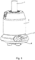
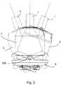
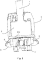
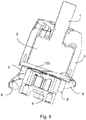
- FIGS. 1-10 show the invention with reference only to the embodiment of a steering control device of the hydraulic type and composed of an axial piston pump supplying pressurized oil to the chambers of an actuating cylinder correspondingly to the direction of rotation and to the rotation angle of the steering wheel and therefore of the drive shaft.
- a steering control device of the hydraulic type composed of an axial piston pump supplying pressurized oil to the chambers of an actuating cylinder correspondingly to the direction of rotation and to the rotation angle of the steering wheel and therefore of the drive shaft.
- inventive idea can be transferred without any inventive steps also to steering systems having other types of control members such as those described hereinbefore in the present description and that is mechanical, electromechanical, electrohydraulic and electronic, namely of the so called Steer by Wire type.
- the shown embodiment provides a control device with an axial piston pump of the conventional type and which is provided in combination with a tilt member applicable to the case of said pump or the distributor valve integrated within said pump.
- a tilt member applicable to the case of said pump or the distributor valve integrated within said pump.
- the case can be integrated with means for the oscillating fastening to the bridge that can be made according to different variants that are all part of the technical basic knowledge of the person skilled in the art and whose specific selection falls within the range of normal opportunity choices that the person skilled in the art has to perform in the designing phase.
- the device according to the invention is provided in combination with a steering control device comprising a drive shaft 1 of a pump, whose rotor 2 is housed in a case 3 closed at the bottom by a base of the pump element 103 shaped like a flange for fastening to a valve body 4.
- the pump is known and it can be of any type and an example of such pump provides a rotor having a plurality of axial compression chambers, which axial chambers surround the drive shaft.
- a piston is axially slidably housed in each chamber and biased by elastic means with one end projecting out of one end side of the corresponding compression chamber against a cam track consisting of an annular plate inclined with respect to the axis of rotation of the rotor such as for example described in the patent application GE2013A000088 to the same applicant and that has to be intended as an integral part of the present description.
- the steering control device is mounted in a bridge, partially or completely embedded in a compartment underneath the panel of the bridge.
- An inner annular element 5 surrounds the periphery of the valve body 4 in a substantially median position.
- Such element 5 has a cylindrical shape and has a pair of holes 105 on diametrically opposite walls.
- Such inner annular element 5 is provided to be fitted inside an outer annular element 6 having corresponding diametral holes 106 intended to receive a pair of pins.
- Such pins allow the two elements 5 and 6 to be articulated according to a diametral axis and therefore to pivot one with respect to each other relative to a median, axial transverse plane.
- the outer annular element 6 is provided to be mounted on the bridge or on the dashboard of a boat at an opening provided in one of the walls of said bridge or said dashboard. Said opening is intended to house the rear part of the assembly composed of the valve 4 and that has a shape corresponding to the first annular element.
- This annular element 6 is like a frame and has a substantially cylindrical shape with conical flares 206 on the walls to allow the inner annular element to tilt more. Flares are provided to house the lower part of the valve body 4 in its interference position with the inner ring 5 tilted to a maximum extent.
- a clamping element 7 is interposed between the outer annular element 6 and the inner annular element 5 allowing the two annular elements to be releasably locked between a maximum negative tilt position and a maximum positive tilt position.
- one of the two holes 105 of the outer annular element 6 is surrounded by a crown of axial teeth 306 intended to abut with a corresponding crown of axial teeth surrounding the corresponding hole of the inner annular element 5 (not shown in figures).
- the clamping element 7 comprises a lever 107 on the pin 207 that acts on a clutch element 307 that axially moves near/away the two crowns to allow/prevent them to/from rotating.
- the lever 107 turns the lever 107 to move away the two front teeth crowns from each other, releasing the two rings for a relative oscillation with respect to each other and tilts the shaft 1 of the device.
- the two rings are again locked with each other and the new position is made stable by meshing the teeth of the crowns.
- the tilt axis defined by the elements 5 and 6 extends diametrically with respect to the axis of the shaft and it intersects the axis coinciding with the axis of the shaft, that is the longitudinal axis of the case 3 and of the shaft 1 and rotor 3 assembly in a point in the lower half of the overall longitudinal extension of the assembly 3 and 4 or of the assembly 1, 3, 4.
- the position of the oscillation or tilt axis in relation to the point of incidence with the axis parallel to the axis of the shaft 1 is comprised in a lower end strip slightly under the case 3 of the pump and coinciding with the distributor valve 4.
- the end strip of the case 3, 4 which is comprised between the lower end thereof, that is the end opposite to that of the shaft 1 and an axial length equal, at most, to 40% of the overall axial length from said lower end of the case 3, 4 to said end of the shaft 1.
- said end strip has an axial length equal to 30% of said overall axial length.
- the shown embodiment provides the specific case where said oscillation or tilt axis is provided in an end strip of the case comprised between the lower end thereof, that is the end opposite to that of the shaft and an axial length equal, at most, to 40% of the axial length of the case 3, 4 from said lower end of the case to the opposite end of the case from which the shaft 1 protrudes.
- said end strip has an axial length equal to 30% of said axial length of the case from said lower end of the case to the opposite end of the case from which the shaft protrudes.
- annular element 6 fastened to the bridge can be slightly elongated according to an axis perpendicular to the axis of the shaft and to the tilt axis. This allows, together with conical flares on the inner edges and curved portions facing the case in the oscillation direction, more empty space to be provided to increase tilt.
- the second annular element 5 can be omitted and the case or the valve 4, depending on the choice and on the type of transmission member, can directly bear the pins 105, 207 that can be as one piece or that can be fastenable for example by being tightened in threaded holes provided in a predetermined position on the body of the case and/or of the valve 4.
- position locking means can be selected among a considerable number of variants that are part of the technical basic knowledge of the person skilled in the art.
- At least the annular element 6 associated with the bridge can have ribs, grooves, projections or fastening seats for one end of an elastic covering dome like a sleeve or the like.
- the other end can be fastened to the annular element 6 associated to the case of the control device to means coupling/fastening said elastic dome or said sleeve provided in other points of the case.
- the device shown in the figures described until now is of the hydraulic type that is with pump transmission member. It is clear how the teaching of the present invention can be extended to any type of steering system.
- the idea at the base of the invention is to cause the drive shaft and together the device generating control pulses or control signals, that is the whole steering control device to rigidly tilt together with the drive shaft, to allow the user to tilt the steering wheel or helm without putting out of alignment or without misaligning with each other the steering wheel and the drive shaft and this sets aside from the type of means used to convert the rotational motion of the steering drive shaft into signals or pulses activating the steering actuator.
- steering systems comprising a mechanical, rotary or rectilinear steering system wherein the rotation of the drive shaft causes the translation of at least one steel cable to drive a mechanical actuator or electromechanical sensors, such as potentiometers, variable capacitors or Hall effect devices, that generate electric signals uniquely associated to the angle position of the same shaft for operating an electric motor actuator, or a electrohydraulic system where the signals generated by the steering wheel through the steering control device are converted into actions supplying pressurized fluid generated by a motorized pump to the chambers of an hydraulic actuator, or combinations thereof, such as for example the servoassisted systems described in the patent application GE2011A000017 .
Landscapes
- Chemical & Material Sciences (AREA)
- Engineering & Computer Science (AREA)
- Combustion & Propulsion (AREA)
- Mechanical Engineering (AREA)
- Ocean & Marine Engineering (AREA)
- Steering Controls (AREA)
Applications Claiming Priority (1)
| Application Number | Priority Date | Filing Date | Title |
|---|---|---|---|
| ITUB2016A000875A ITUB20160875A1 (it) | 2016-02-19 | 2016-02-19 | Dispositivo di comando di sterzatura di imbarcazioni |
Publications (2)
| Publication Number | Publication Date |
|---|---|
| EP3208186A1 true EP3208186A1 (fr) | 2017-08-23 |
| EP3208186B1 EP3208186B1 (fr) | 2021-07-07 |
Family
ID=56027024
Family Applications (1)
| Application Number | Title | Priority Date | Filing Date |
|---|---|---|---|
| EP17156818.1A Active EP3208186B1 (fr) | 2016-02-19 | 2017-02-20 | Dispositif de commande de direction de bateau |
Country Status (3)
| Country | Link |
|---|---|
| US (1) | US10011340B2 (fr) |
| EP (1) | EP3208186B1 (fr) |
| IT (1) | ITUB20160875A1 (fr) |
Families Citing this family (3)
| Publication number | Priority date | Publication date | Assignee | Title |
|---|---|---|---|---|
| JP7203327B2 (ja) | 2020-07-30 | 2023-01-13 | 日本発條株式会社 | ヘルム装置 |
| USD1083741S1 (en) * | 2023-09-29 | 2025-07-15 | Dometic Marine Canada Inc. | Fixed mount steering helm |
| CN120039393B (zh) * | 2025-02-27 | 2025-11-07 | 中国人民解放军海军士官学校 | 一种船舶液压舵机传动拉杆装置 |
Citations (7)
| Publication number | Priority date | Publication date | Assignee | Title |
|---|---|---|---|---|
| US2926545A (en) * | 1958-08-07 | 1960-03-01 | Vollrath Co | Adjustable mountings for boat steering mechanisms |
| EP1150453A2 (fr) | 2000-04-26 | 2001-10-31 | Semiconductor Energy Laboratory Co., Ltd. | Système et procédé de communication pour l'identification d'un individu au moyen d'information biologique |
| EP1510453A1 (fr) * | 2003-08-29 | 2005-03-02 | Teleflex Canada Incorporated | Dispositif et méthode de gouvernail d'embarcation |
| US20050166819A1 (en) | 2004-01-30 | 2005-08-04 | Zeiger Donald J. | Tilt helm |
| US20060118022A1 (en) | 2004-12-06 | 2006-06-08 | Katsuhiko Sasayama | Manual hydraulic steering apparatus |
| ITGE20110017A1 (it) | 2011-02-16 | 2012-08-17 | Ultraflex Spa | Dispositivo di sterzatura servoassistita |
| ITGE20130088A1 (it) | 2013-09-16 | 2015-03-17 | Ultraflex Spa | Pompa a stantuffi |
Family Cites Families (4)
| Publication number | Priority date | Publication date | Assignee | Title |
|---|---|---|---|---|
| US2826090A (en) * | 1955-01-27 | 1958-03-11 | Supreme Foundry Inc | Boat steering controls |
| US3395930A (en) * | 1966-03-07 | 1968-08-06 | Int Harvester Co | Tiltable steering wheel |
| US5136894B1 (en) * | 1990-08-31 | 1996-10-15 | Bankers Trust Co | Tiltable marine steering helm |
| US5676081A (en) * | 1995-11-13 | 1997-10-14 | Kobelt; Jacob | Tilting helm for marine vessel |
-
2016
- 2016-02-19 IT ITUB2016A000875A patent/ITUB20160875A1/it unknown
-
2017
- 2017-02-17 US US15/436,756 patent/US10011340B2/en active Active
- 2017-02-20 EP EP17156818.1A patent/EP3208186B1/fr active Active
Patent Citations (7)
| Publication number | Priority date | Publication date | Assignee | Title |
|---|---|---|---|---|
| US2926545A (en) * | 1958-08-07 | 1960-03-01 | Vollrath Co | Adjustable mountings for boat steering mechanisms |
| EP1150453A2 (fr) | 2000-04-26 | 2001-10-31 | Semiconductor Energy Laboratory Co., Ltd. | Système et procédé de communication pour l'identification d'un individu au moyen d'information biologique |
| EP1510453A1 (fr) * | 2003-08-29 | 2005-03-02 | Teleflex Canada Incorporated | Dispositif et méthode de gouvernail d'embarcation |
| US20050166819A1 (en) | 2004-01-30 | 2005-08-04 | Zeiger Donald J. | Tilt helm |
| US20060118022A1 (en) | 2004-12-06 | 2006-06-08 | Katsuhiko Sasayama | Manual hydraulic steering apparatus |
| ITGE20110017A1 (it) | 2011-02-16 | 2012-08-17 | Ultraflex Spa | Dispositivo di sterzatura servoassistita |
| ITGE20130088A1 (it) | 2013-09-16 | 2015-03-17 | Ultraflex Spa | Pompa a stantuffi |
Also Published As
| Publication number | Publication date |
|---|---|
| EP3208186B1 (fr) | 2021-07-07 |
| US10011340B2 (en) | 2018-07-03 |
| US20170240260A1 (en) | 2017-08-24 |
| ITUB20160875A1 (it) | 2017-08-19 |
Similar Documents
| Publication | Publication Date | Title |
|---|---|---|
| EP3208186B1 (fr) | Dispositif de commande de direction de bateau | |
| EP3326903B1 (fr) | Système de commande de bateau | |
| US10011342B2 (en) | Directional control system for a boat | |
| AU2019203806B2 (en) | Retractable thruster and drive shaft for retractable thruster | |
| EP3228523A1 (fr) | Système de direction hydraulique pour véhicules, en particulier pour embarcations ou semblable | |
| KR19980024658A (ko) | 사이클로이드 프로펠라 | |
| WO2002061278A2 (fr) | Cylindre hydraulique a montage antirotation de tige de piston | |
| CA2895863C (fr) | Propulseur electrique a direction assistee | |
| EP3000717B1 (fr) | Appareil auxiliaire de contrôle pour bateau | |
| KR100559844B1 (ko) | 스티어링휠의 틸팅 및 텔레스코픽 장치 | |
| JP2019182296A (ja) | 車両用操舵装置 | |
| EP2899114A1 (fr) | Dispositif d'engrenage marin | |
| US9555878B2 (en) | Rotor blade control device | |
| US10196121B2 (en) | Steering actuator and control method | |
| EP3246225B1 (fr) | Colonne de direction tiltable multifonctionnelle pour véhicules industriels | |
| KR101887475B1 (ko) | 전동 액추에이터 | |
| KR20230023152A (ko) | 전동식 동력 보조 조향장치 | |
| EP3789287B1 (fr) | Système de direction pour bateaux, embarcations ou similaires | |
| JP2021006428A (ja) | 船外機 | |
| EP3156319B1 (fr) | Dispositif de changement de position d'hélice | |
| WO2017216702A1 (fr) | Appareil pour varier la direction de déplacement d'un véhicule, en particulier un véhicule marin | |
| WO2015190983A1 (fr) | Actionneur, dispositif d'inclinaison de cabine, véhicule et procédé pour commander un actionneur | |
| KR101465137B1 (ko) | 자동차용 사이드미러장치 | |
| CN115705071A (zh) | 控制装置 | |
| EP1092893B1 (fr) | Timonerie motorisée |
Legal Events
| Date | Code | Title | Description |
|---|---|---|---|
| PUAI | Public reference made under article 153(3) epc to a published international application that has entered the european phase |
Free format text: ORIGINAL CODE: 0009012 |
|
| STAA | Information on the status of an ep patent application or granted ep patent |
Free format text: STATUS: THE APPLICATION HAS BEEN PUBLISHED |
|
| AK | Designated contracting states |
Kind code of ref document: A1 Designated state(s): AL AT BE BG CH CY CZ DE DK EE ES FI FR GB GR HR HU IE IS IT LI LT LU LV MC MK MT NL NO PL PT RO RS SE SI SK SM TR |
|
| AX | Request for extension of the european patent |
Extension state: BA ME |
|
| STAA | Information on the status of an ep patent application or granted ep patent |
Free format text: STATUS: REQUEST FOR EXAMINATION WAS MADE |
|
| 17P | Request for examination filed |
Effective date: 20180219 |
|
| RBV | Designated contracting states (corrected) |
Designated state(s): AL AT BE BG CH CY CZ DE DK EE ES FI FR GB GR HR HU IE IS IT LI LT LU LV MC MK MT NL NO PL PT RO RS SE SI SK SM TR |
|
| STAA | Information on the status of an ep patent application or granted ep patent |
Free format text: STATUS: EXAMINATION IS IN PROGRESS |
|
| 17Q | First examination report despatched |
Effective date: 20190327 |
|
| GRAP | Despatch of communication of intention to grant a patent |
Free format text: ORIGINAL CODE: EPIDOSNIGR1 |
|
| STAA | Information on the status of an ep patent application or granted ep patent |
Free format text: STATUS: GRANT OF PATENT IS INTENDED |
|
| INTG | Intention to grant announced |
Effective date: 20210303 |
|
| GRAS | Grant fee paid |
Free format text: ORIGINAL CODE: EPIDOSNIGR3 |
|
| GRAA | (expected) grant |
Free format text: ORIGINAL CODE: 0009210 |
|
| STAA | Information on the status of an ep patent application or granted ep patent |
Free format text: STATUS: THE PATENT HAS BEEN GRANTED |
|
| AK | Designated contracting states |
Kind code of ref document: B1 Designated state(s): AL AT BE BG CH CY CZ DE DK EE ES FI FR GB GR HR HU IE IS IT LI LT LU LV MC MK MT NL NO PL PT RO RS SE SI SK SM TR |
|
| REG | Reference to a national code |
Ref country code: GB Ref legal event code: FG4D |
|
| REG | Reference to a national code |
Ref country code: AT Ref legal event code: REF Ref document number: 1408355 Country of ref document: AT Kind code of ref document: T Effective date: 20210715 |
|
| REG | Reference to a national code |
Ref country code: DE Ref legal event code: R096 Ref document number: 602017041508 Country of ref document: DE |
|
| REG | Reference to a national code |
Ref country code: IE Ref legal event code: FG4D |
|
| REG | Reference to a national code |
Ref country code: SE Ref legal event code: TRGR |
|
| REG | Reference to a national code |
Ref country code: LT Ref legal event code: MG9D |
|
| REG | Reference to a national code |
Ref country code: AT Ref legal event code: MK05 Ref document number: 1408355 Country of ref document: AT Kind code of ref document: T Effective date: 20210707 |
|
| REG | Reference to a national code |
Ref country code: NL Ref legal event code: FP |
|
| PG25 | Lapsed in a contracting state [announced via postgrant information from national office to epo] |
Ref country code: RS Free format text: LAPSE BECAUSE OF FAILURE TO SUBMIT A TRANSLATION OF THE DESCRIPTION OR TO PAY THE FEE WITHIN THE PRESCRIBED TIME-LIMIT Effective date: 20210707 Ref country code: LT Free format text: LAPSE BECAUSE OF FAILURE TO SUBMIT A TRANSLATION OF THE DESCRIPTION OR TO PAY THE FEE WITHIN THE PRESCRIBED TIME-LIMIT Effective date: 20210707 Ref country code: BG Free format text: LAPSE BECAUSE OF FAILURE TO SUBMIT A TRANSLATION OF THE DESCRIPTION OR TO PAY THE FEE WITHIN THE PRESCRIBED TIME-LIMIT Effective date: 20211007 Ref country code: AT Free format text: LAPSE BECAUSE OF FAILURE TO SUBMIT A TRANSLATION OF THE DESCRIPTION OR TO PAY THE FEE WITHIN THE PRESCRIBED TIME-LIMIT Effective date: 20210707 Ref country code: PT Free format text: LAPSE BECAUSE OF FAILURE TO SUBMIT A TRANSLATION OF THE DESCRIPTION OR TO PAY THE FEE WITHIN THE PRESCRIBED TIME-LIMIT Effective date: 20211108 Ref country code: NO Free format text: LAPSE BECAUSE OF FAILURE TO SUBMIT A TRANSLATION OF THE DESCRIPTION OR TO PAY THE FEE WITHIN THE PRESCRIBED TIME-LIMIT Effective date: 20211007 Ref country code: FI Free format text: LAPSE BECAUSE OF FAILURE TO SUBMIT A TRANSLATION OF THE DESCRIPTION OR TO PAY THE FEE WITHIN THE PRESCRIBED TIME-LIMIT Effective date: 20210707 Ref country code: ES Free format text: LAPSE BECAUSE OF FAILURE TO SUBMIT A TRANSLATION OF THE DESCRIPTION OR TO PAY THE FEE WITHIN THE PRESCRIBED TIME-LIMIT Effective date: 20210707 Ref country code: HR Free format text: LAPSE BECAUSE OF FAILURE TO SUBMIT A TRANSLATION OF THE DESCRIPTION OR TO PAY THE FEE WITHIN THE PRESCRIBED TIME-LIMIT Effective date: 20210707 |
|
| PG25 | Lapsed in a contracting state [announced via postgrant information from national office to epo] |
Ref country code: PL Free format text: LAPSE BECAUSE OF FAILURE TO SUBMIT A TRANSLATION OF THE DESCRIPTION OR TO PAY THE FEE WITHIN THE PRESCRIBED TIME-LIMIT Effective date: 20210707 Ref country code: LV Free format text: LAPSE BECAUSE OF FAILURE TO SUBMIT A TRANSLATION OF THE DESCRIPTION OR TO PAY THE FEE WITHIN THE PRESCRIBED TIME-LIMIT Effective date: 20210707 Ref country code: GR Free format text: LAPSE BECAUSE OF FAILURE TO SUBMIT A TRANSLATION OF THE DESCRIPTION OR TO PAY THE FEE WITHIN THE PRESCRIBED TIME-LIMIT Effective date: 20211008 |
|
| REG | Reference to a national code |
Ref country code: DE Ref legal event code: R097 Ref document number: 602017041508 Country of ref document: DE |
|
| PG25 | Lapsed in a contracting state [announced via postgrant information from national office to epo] |
Ref country code: DK Free format text: LAPSE BECAUSE OF FAILURE TO SUBMIT A TRANSLATION OF THE DESCRIPTION OR TO PAY THE FEE WITHIN THE PRESCRIBED TIME-LIMIT Effective date: 20210707 |
|
| PLBE | No opposition filed within time limit |
Free format text: ORIGINAL CODE: 0009261 |
|
| STAA | Information on the status of an ep patent application or granted ep patent |
Free format text: STATUS: NO OPPOSITION FILED WITHIN TIME LIMIT |
|
| PG25 | Lapsed in a contracting state [announced via postgrant information from national office to epo] |
Ref country code: SM Free format text: LAPSE BECAUSE OF FAILURE TO SUBMIT A TRANSLATION OF THE DESCRIPTION OR TO PAY THE FEE WITHIN THE PRESCRIBED TIME-LIMIT Effective date: 20210707 Ref country code: SK Free format text: LAPSE BECAUSE OF FAILURE TO SUBMIT A TRANSLATION OF THE DESCRIPTION OR TO PAY THE FEE WITHIN THE PRESCRIBED TIME-LIMIT Effective date: 20210707 Ref country code: RO Free format text: LAPSE BECAUSE OF FAILURE TO SUBMIT A TRANSLATION OF THE DESCRIPTION OR TO PAY THE FEE WITHIN THE PRESCRIBED TIME-LIMIT Effective date: 20210707 Ref country code: EE Free format text: LAPSE BECAUSE OF FAILURE TO SUBMIT A TRANSLATION OF THE DESCRIPTION OR TO PAY THE FEE WITHIN THE PRESCRIBED TIME-LIMIT Effective date: 20210707 Ref country code: CZ Free format text: LAPSE BECAUSE OF FAILURE TO SUBMIT A TRANSLATION OF THE DESCRIPTION OR TO PAY THE FEE WITHIN THE PRESCRIBED TIME-LIMIT Effective date: 20210707 Ref country code: AL Free format text: LAPSE BECAUSE OF FAILURE TO SUBMIT A TRANSLATION OF THE DESCRIPTION OR TO PAY THE FEE WITHIN THE PRESCRIBED TIME-LIMIT Effective date: 20210707 |
|
| 26N | No opposition filed |
Effective date: 20220408 |
|
| REG | Reference to a national code |
Ref country code: DE Ref legal event code: R119 Ref document number: 602017041508 Country of ref document: DE |
|
| PG25 | Lapsed in a contracting state [announced via postgrant information from national office to epo] |
Ref country code: MC Free format text: LAPSE BECAUSE OF FAILURE TO SUBMIT A TRANSLATION OF THE DESCRIPTION OR TO PAY THE FEE WITHIN THE PRESCRIBED TIME-LIMIT Effective date: 20210707 |
|
| REG | Reference to a national code |
Ref country code: CH Ref legal event code: PL |
|
| REG | Reference to a national code |
Ref country code: BE Ref legal event code: MM Effective date: 20220228 |
|
| PG25 | Lapsed in a contracting state [announced via postgrant information from national office to epo] |
Ref country code: LU Free format text: LAPSE BECAUSE OF NON-PAYMENT OF DUE FEES Effective date: 20220220 |
|
| PG25 | Lapsed in a contracting state [announced via postgrant information from national office to epo] |
Ref country code: LI Free format text: LAPSE BECAUSE OF NON-PAYMENT OF DUE FEES Effective date: 20220228 Ref country code: IE Free format text: LAPSE BECAUSE OF NON-PAYMENT OF DUE FEES Effective date: 20220220 Ref country code: DE Free format text: LAPSE BECAUSE OF NON-PAYMENT OF DUE FEES Effective date: 20220901 Ref country code: CH Free format text: LAPSE BECAUSE OF NON-PAYMENT OF DUE FEES Effective date: 20220228 |
|
| PG25 | Lapsed in a contracting state [announced via postgrant information from national office to epo] |
Ref country code: BE Free format text: LAPSE BECAUSE OF NON-PAYMENT OF DUE FEES Effective date: 20220228 |
|
| PGFP | Annual fee paid to national office [announced via postgrant information from national office to epo] |
Ref country code: NL Payment date: 20230131 Year of fee payment: 7 |
|
| PGFP | Annual fee paid to national office [announced via postgrant information from national office to epo] |
Ref country code: SE Payment date: 20230125 Year of fee payment: 7 |
|
| PG25 | Lapsed in a contracting state [announced via postgrant information from national office to epo] |
Ref country code: HU Free format text: LAPSE BECAUSE OF FAILURE TO SUBMIT A TRANSLATION OF THE DESCRIPTION OR TO PAY THE FEE WITHIN THE PRESCRIBED TIME-LIMIT; INVALID AB INITIO Effective date: 20170220 |
|
| PG25 | Lapsed in a contracting state [announced via postgrant information from national office to epo] |
Ref country code: MK Free format text: LAPSE BECAUSE OF FAILURE TO SUBMIT A TRANSLATION OF THE DESCRIPTION OR TO PAY THE FEE WITHIN THE PRESCRIBED TIME-LIMIT Effective date: 20210707 Ref country code: CY Free format text: LAPSE BECAUSE OF FAILURE TO SUBMIT A TRANSLATION OF THE DESCRIPTION OR TO PAY THE FEE WITHIN THE PRESCRIBED TIME-LIMIT Effective date: 20210707 |
|
| PG25 | Lapsed in a contracting state [announced via postgrant information from national office to epo] |
Ref country code: TR Free format text: LAPSE BECAUSE OF FAILURE TO SUBMIT A TRANSLATION OF THE DESCRIPTION OR TO PAY THE FEE WITHIN THE PRESCRIBED TIME-LIMIT Effective date: 20210707 |
|
| PG25 | Lapsed in a contracting state [announced via postgrant information from national office to epo] |
Ref country code: MT Free format text: LAPSE BECAUSE OF FAILURE TO SUBMIT A TRANSLATION OF THE DESCRIPTION OR TO PAY THE FEE WITHIN THE PRESCRIBED TIME-LIMIT Effective date: 20210707 |
|
| REG | Reference to a national code |
Ref country code: SE Ref legal event code: EUG |
|
| REG | Reference to a national code |
Ref country code: NL Ref legal event code: MM Effective date: 20240301 |
|
| PG25 | Lapsed in a contracting state [announced via postgrant information from national office to epo] |
Ref country code: NL Free format text: LAPSE BECAUSE OF NON-PAYMENT OF DUE FEES Effective date: 20240301 |
|
| PG25 | Lapsed in a contracting state [announced via postgrant information from national office to epo] |
Ref country code: NL Free format text: LAPSE BECAUSE OF NON-PAYMENT OF DUE FEES Effective date: 20240301 |
|
| PG25 | Lapsed in a contracting state [announced via postgrant information from national office to epo] |
Ref country code: SE Free format text: LAPSE BECAUSE OF NON-PAYMENT OF DUE FEES Effective date: 20240221 |
|
| PGFP | Annual fee paid to national office [announced via postgrant information from national office to epo] |
Ref country code: GB Payment date: 20260126 Year of fee payment: 10 |
|
| PGFP | Annual fee paid to national office [announced via postgrant information from national office to epo] |
Ref country code: IT Payment date: 20260128 Year of fee payment: 10 |
|
| PGFP | Annual fee paid to national office [announced via postgrant information from national office to epo] |
Ref country code: FR Payment date: 20260126 Year of fee payment: 10 |