EP3208220A1 - Appareil d'enregistrement - Google Patents
Appareil d'enregistrement Download PDFInfo
- Publication number
- EP3208220A1 EP3208220A1 EP17155477.7A EP17155477A EP3208220A1 EP 3208220 A1 EP3208220 A1 EP 3208220A1 EP 17155477 A EP17155477 A EP 17155477A EP 3208220 A1 EP3208220 A1 EP 3208220A1
- Authority
- EP
- European Patent Office
- Prior art keywords
- pressing roller
- medium
- transport belt
- recording apparatus
- belt
- Prior art date
- Legal status (The legal status is an assumption and is not a legal conclusion. Google has not performed a legal analysis and makes no representation as to the accuracy of the status listed.)
- Granted
Links
Images



Classifications
-
- B—PERFORMING OPERATIONS; TRANSPORTING
- B41—PRINTING; LINING MACHINES; TYPEWRITERS; STAMPS
- B41J—TYPEWRITERS; SELECTIVE PRINTING MECHANISMS, i.e. MECHANISMS PRINTING OTHERWISE THAN FROM A FORME; CORRECTION OF TYPOGRAPHICAL ERRORS
- B41J15/00—Devices or arrangements of selective printing mechanisms, e.g. ink-jet printers or thermal printers, specially adapted for supporting or handling copy material in continuous form, e.g. webs
- B41J15/04—Supporting, feeding, or guiding devices; Mountings for web rolls or spindles
-
- B—PERFORMING OPERATIONS; TRANSPORTING
- B41—PRINTING; LINING MACHINES; TYPEWRITERS; STAMPS
- B41J—TYPEWRITERS; SELECTIVE PRINTING MECHANISMS, i.e. MECHANISMS PRINTING OTHERWISE THAN FROM A FORME; CORRECTION OF TYPOGRAPHICAL ERRORS
- B41J11/00—Devices or arrangements of selective printing mechanisms, e.g. ink-jet printers or thermal printers, for supporting or handling copy material in sheet or web form
- B41J11/02—Platens
- B41J11/04—Roller platens
-
- B—PERFORMING OPERATIONS; TRANSPORTING
- B41—PRINTING; LINING MACHINES; TYPEWRITERS; STAMPS
- B41J—TYPEWRITERS; SELECTIVE PRINTING MECHANISMS, i.e. MECHANISMS PRINTING OTHERWISE THAN FROM A FORME; CORRECTION OF TYPOGRAPHICAL ERRORS
- B41J15/00—Devices or arrangements of selective printing mechanisms, e.g. ink-jet printers or thermal printers, specially adapted for supporting or handling copy material in continuous form, e.g. webs
- B41J15/04—Supporting, feeding, or guiding devices; Mountings for web rolls or spindles
- B41J15/048—Conveyor belts or like feeding devices
-
- B—PERFORMING OPERATIONS; TRANSPORTING
- B65—CONVEYING; PACKING; STORING; HANDLING THIN OR FILAMENTARY MATERIAL
- B65H—HANDLING THIN OR FILAMENTARY MATERIAL, e.g. SHEETS, WEBS, CABLES
- B65H20/00—Advancing webs
- B65H20/06—Advancing webs by friction band
-
- B—PERFORMING OPERATIONS; TRANSPORTING
- B65—CONVEYING; PACKING; STORING; HANDLING THIN OR FILAMENTARY MATERIAL
- B65H—HANDLING THIN OR FILAMENTARY MATERIAL, e.g. SHEETS, WEBS, CABLES
- B65H5/00—Feeding articles separated from piles; Feeding articles to machines
- B65H5/02—Feeding articles separated from piles; Feeding articles to machines by belts or chains, e.g. between belts or chains
- B65H5/021—Feeding articles separated from piles; Feeding articles to machines by belts or chains, e.g. between belts or chains by belts
- B65H5/025—Feeding articles separated from piles; Feeding articles to machines by belts or chains, e.g. between belts or chains by belts between belts and rotary means, e.g. rollers, drums, cylinders or balls, forming a transport nip
-
- B—PERFORMING OPERATIONS; TRANSPORTING
- B65—CONVEYING; PACKING; STORING; HANDLING THIN OR FILAMENTARY MATERIAL
- B65H—HANDLING THIN OR FILAMENTARY MATERIAL, e.g. SHEETS, WEBS, CABLES
- B65H2404/00—Parts for transporting or guiding the handled material
- B65H2404/20—Belts
- B65H2404/26—Particular arrangement of belt, or belts
- B65H2404/261—Arrangement of belts, or belt(s) / roller(s) facing each other for forming a transport nip
- B65H2404/2614—Means for engaging or disengaging belts into or out of contact with opposite belts, rollers or balls
Definitions
- the present invention relates to printing apparatuses.
- Such recording apparatuses include a transport belt for transporting a medium and perform recording on the medium transported by the stated transport belt.
- JP-A-2009-256811 , JP-A-2015-157269 , and JP-A-2011-51165 disclose ink jet recording apparatuses that perform recording by ejecting ink onto a medium which is transported by a transport belt.
- recording apparatuses that include a transport belt for transporting a medium.
- recording apparatuses equipped with a pressing roller (paste roller, pressure roller) configured to press the medium against the transport belt as disclosed in JP-A-2009-256811 and JP-A-2015-157269
- a recording apparatus equipped with a support unit (attraction platen) capable of supporting the transport belt as disclosed in JP-A-2011-51165 , and so on.
- the medium can be supported by the transport belt with certainty.
- a friction force between the transport belt and the support unit is increased in some cases, depending on the adopted structure.
- An advantage of some aspects of the invention is to make a transport belt support a medium with certainty and suppress an increase in friction force between the transport belt and a support unit capable of supporting the transport belt.
- a recording apparatus includes a transport belt for transporting a medium, a pressing roller configured to press the medium against the transport belt, and a support unit capable of supporting the transport belt; the transport belt and the support unit make contact with each other when the pressing roller is pressed against the medium.
- the transport belt, the pressing roller, and the support unit are included, and the transport belt and the support unit make contact with each other when the pressing roller is pressed against the medium.
- the medium can be pressed against the transport belt with certainty by causing the transport belt and the support unit to make contact with each other; in the case where the pressing roller does not need to be pressed against the medium at a non-recording time or the like, the transport belt and the support unit can be distanced from each other, a contact force between the transport belt and the support unit can be weakened, and so on.
- a recording apparatus is such that, in the first aspect, the transport belt and the support unit are distanced from each other when the pressing roller is distanced from the medium.
- the transport belt and the support unit are distanced from each other when the pressing roller is distanced from the medium. This makes it possible to suppress the increase in friction force between the transport belt and the support unit capable of supporting the transport belt by making the transport belt and the support unit distanced from each other when the pressing roller does not need to be pressed against the medium.
- a recording apparatus is such that, in the first or second aspect, the pressing roller is pressed against the medium under its own weight.
- the pressing roller is pressed against the medium under its own weight. This makes it possible to easily form a mechanism that presses the pressing roller against the medium.
- a recording apparatus is such that, in any one of the first to third aspects, a force of equal to or less than half the own weight of the pressing roller is applied to the support unit when the pressing roller is pressed against the medium.
- a force of equal to or less than half the own weight of the pressing roller is applied to the support unit when the pressing roller is pressed against the medium.
- the force applied to the support unit, when the pressing roller is pressed against the medium is reduced to be equal to or less than half the own weight of the pressing roller.
- a recording apparatus is such that, in any one of the first to fourth aspects, the pressing roller can move along a movement direction intersecting with a direction in which the pressing roller is pressed against the medium.
- the pressing roller can move along the movement direction intersecting with a direction in which the pressing roller is pressed against the medium.
- a situation where the pressing roller makes contact with the medium at the same position for a long time can be suppressed by moving the pressing roller along the movement direction when the pressing roller is pressed against the medium. This makes it possible to suppress the formation of a contact mark due to the pressing roller being pressed against the medium.
- a recording apparatus is such that, in the fifth aspect, the support unit has a support range equal to or larger than a movement range of the pressing roller in the movement direction.
- the support unit has the support range equal to or larger than the movement range of the pressing roller in the movement direction. This makes it possible for the support unit to support the transport belt, which is pressed by the pressing roller with the medium interposed therebetween, across the overall movement range of the pressing roller.
- Fig. 1 is a schematic side view of the recording apparatus 1 according to the embodiment.
- the recording apparatus 1 of the embodiment includes: a feeding section 2 capable of feeding out a roll R1 of a target recording medium (medium) P on which recording is performed; a transport mechanism 3 configured to transport the target recording medium P in a transport direction A using an adhesive belt 10 (a transport belt constituted of an endless belt) that supports the target recording medium P on a support surface F to which an adhesive agent is attached; a recording mechanism 4 configured to record on the target recording medium P by causing a carriage 16 equipped with a recording head 7 for ejecting ink to scan back and forth in a reciprocating movement direction B which intersects with the transport direction A of the target recording medium P; a washing mechanism 15 of the adhesive belt 10; and a winding mechanism 38 having a winding shaft 17 for winding the target recording medium P.
- a feeding section 2 capable of feeding out a roll R1 of a target recording medium (medium) P on which recording is performed
- a transport mechanism 3 configured to transport the target recording medium P in a transport direction A using an adhesive belt 10 (a transport
- the feeding section 2 includes a rotational shaft 5 that serves as a setting position of the roll R1 of the target recording medium P on which recording is performed.
- the feeding section 2 is so constituted as to be capable of feeding out the target recording medium P from the roll R1 which is set on the rotational shaft 5, via slave rollers 6 and 37, to the transport mechanism 3.
- the rotational shaft 5 rotates in a rotational direction C when feeding out the target recording medium P to the transport mechanism 3.
- the transport mechanism 3 includes the adhesive belt 10 which transports the target recording medium P fed out from the feeding section 2 while placing the target recording medium P thereon, a driving roller 8 for moving the adhesive belt 10 in a direction E, and a slave roller 9.
- the target recording medium P is pressed against the support surface F of the adhesive belt 10 by a pressing roller 12 to be pasted and placed on the support surface F.
- the driving roller 8 rotates in the rotational direction C when transporting the target recording medium P.
- endless belt serving as the transport belt is not limited to an adhesive belt.
- an electrostatic attraction-type endless belt may be used instead.
- a platen 18 and support portions 19, 20 are provided as a support unit capable of supporting the adhesive belt 10. Because of the adhesive belt 10 being supported by the platen 18 and the support portions 19 and 20, vibration of the adhesive belt 10 due to the movement of the adhesive belt 10, or the like can be suppressed.
- the platen 18 is provided in a region opposing the recording head 7 with the adhesive belt 10 interposed therebetween
- the support portion 19 is provided in a region opposing the pressing roller 12 with the adhesive belt 10 interposed therebetween
- the support portion 20 is provided between the platen 18 and the support portion 19.
- the pressing roller 12 of the embodiment is so constituted as to be capable of moving back and forth (swinging) along the transport direction A in order to suppress a situation where a contact mark is formed on the target recording medium P due to the pressing roller 12 making contact with the target recording medium P at the same place for a constant time. This will be explained later in detail. Note that, however, the pressing roller 12 is not limited to the above-mentioned constitution.
- the recording mechanism 4 includes a carriage motor 30 (see Fig. 2 ) to move the carriage 16 equipped with the recording head 7 back and forth in the reciprocating movement direction B.
- the reciprocating movement direction B is a direction perpendicular to the depiction in Fig. 1 (i.e. is into and out of the plane of the sheet on which Fig. 1 is depicted).
- the transport mechanism 3 stops the transport of the target recording medium P.
- the reciprocating scanning of the carriage 16 and the transport of the target recording medium P are carried out alternately.
- the transport mechanism 3 intermittently transports the target recording medium P (intermittently moves the adhesive belt 10).
- the recording apparatus 1 of this embodiment includes the recording head 7 configured to eject ink while moving back and forth in the reciprocating movement direction B, a printing apparatus including what is called a line head in which a plurality of nozzles for ejecting ink are provided in an intersection direction intersecting with the movement direction of the target recording medium P may be employed instead.
- line head refers to a recording head used in a recording apparatus, where a nozzle region formed in the intersection direction intersecting with the movement direction of the target recording medium P is so provided as to be capable of covering the overall area in the intersection direction, and an image is formed by relatively moving the recording head or the target recording medium P. It may not be necessary that the nozzle region formed in the intersection direction of the line head be capable of covering the intersection direction of every medium that the recording apparatus corresponds.
- the washing mechanism 15 of the adhesive belt 10 includes a washing brush 13 constituted of a plurality of washing rollers linked in a rotational shaft direction, and a tray 14 containing a washing agent for washing the washing brush 13.
- the winding mechanism 38 is a mechanism for winding the target recording medium P, on which recording has been performed, that is transported from the transport mechanism 3 via a slave roller 11.
- a paper core or the like for winding the medium is set on the winding shaft 17 and then the target recording medium P is wound thereupon, whereby the target recording medium P can be wound as a roll R2 of the target recording medium P.
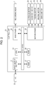
- Fig. 2 is a block diagram of the recording apparatus 1 of the embodiment.
- a CPU 24 which supervises the overall control of the recording apparatus 1 is provided.
- the CPU 24 is connected, through a system bus 25, to a ROM 26 in which various control programs to be executed by the CPU 24, and the like are stored, and to a RAM 27 in which data can be temporarily stored.
- the CPU 24 is connected, through the system bus 25, to a head driver 28 configured to drive the recording head 7.
- the CPU 24 is connected, through the system bus 25, to a motor driver 29 configured to drive a carriage motor 30, a transport motor 31, a feeding motor 32, a winding motor 33, and a swing motor 34.
- the carriage motor 30 is a motor to move the carriage 16 equipped with the recording head 7.
- the transport motor 31 is a motor to drive the driving roller 8.
- the feeding motor 32 is a rotation mechanism of the rotational shaft 5, and is a motor to drive the rotational shaft 5 so as to send the target recording medium P to the transport mechanism 3.
- the winding motor 33 is a driving motor to rotate the winding shaft 17.
- the swing motor 34 is a driving motor to swing (move back and forth) the pressing roller 12 along the transport direction A.
- the CPU 24 is connected to the input-output section 21 through the system bus 25, and the input-output section 21 is connected to a PC 22 configured to send and receive data, such as recording data and the like, and signals.
- the control unit 23 with the above-discussed constitution, can carry out the overall control of the recording apparatus 1.
- Fig. 3 is a schematic side view illustrating the periphery of the pressing roller 12 and the support portion 19 as a principal portion of the recording apparatus 1 of the embodiment.
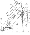
- Fig. 4 is a schematic perspective view illustrating the periphery of the pressing roller 12 and the support portion 19 as a principal portion of the recording apparatus 1 of the embodiment.
- Figs. 5 and 6 are schematic side views illustrating the periphery of the pressing roller 12 and the support portion 19; to be specific, Fig. 5 illustrates a state where the pressing roller 12 is pressed against the target recording medium P (adhesive belt 10), while Fig. 6 illustrates a state where the pressing roller 12 is distanced (spaced) from the target recording medium P (adhesive belt 10).
- the support portion 19 is provided at a position opposing the pressing roller 12.
- the pressing roller 12 is connected to a second rotational member 40 via arm members 41 and 42.
- the second rotational member 40 is connected to the swing motor 34 via a belt 39 and a first rotational member 36.
- a swing mechanism 35 is formed by the swing motor 34, the first rotational member 36, the belt 39, the second rotational member 40, and the arm members 41 and 42.
- the recording apparatus 1 of the embodiment includes, as discussed above, the adhesive belt 10 for transporting the target recording medium P, the pressing roller 12 configured to press the target recording medium P against the adhesive belt 10, and the support portion 19 capable of supporting the adhesive belt 10.
- the adhesive belt 10 and the support portion 19 are so constituted as to be in contact with each other when the pressing roller 12 is pressed against the target recording medium P.
- the target recording medium P can be pressed against the adhesive belt 10 with certainty by causing the adhesive belt 10 and the support portion 19 to make contact with each other; in the case where the pressing roller 12 does not need to be pressed against the target recording medium P at the non-recording time or the like, the adhesive belt 10 and the support portion 19 can be distanced from each other, or a contact force between the adhesive belt 10 and the support portion 19 can be weakened.
- the recording apparatus 1 of the embodiment is constituted so that the adhesive belt 10 and the support portion 19 are distanced from each other when the pressing roller 12 is distanced from the target recording medium P. This suppresses the increase in friction force between the adhesive belt 10 and the support portion 19 capable of supporting the adhesive belt 10 by making the adhesive belt 10 and the support portion 19 be distanced from each other when the pressing roller 12 does not need to be pressed against the target recording medium P.
- the pressing roller 12 is so constituted as to be pressed against the target recording medium P under its own weight. This makes it possible to omit from additionally providing a pressure mechanism or the like in order to press (apply pressure to) the pressing roller 12 against the target recording medium P, whereby a mechanism to press the pressing roller 12 against the target recording medium P can be formed with ease.
- the recording apparatus 1 of the embodiment is constituted so that only a force of equal to or less than half the own weight of the pressing roller 12 is applied to the support portion 19 when the pressing roller 12 is pressed against the target recording medium P by adjusting the tension of the adhesive belt 10 (tension produced by the adhesive belt 10 being hung across the driving roller 8 and the slave roller 9).
- the force applied to the support portion 19 when the pressing roller 12 is pressed against the target recording medium P is reduced to be equal to or less than half the own weight of the pressing roller 12. This makes it possible to suppress the increase in friction force between the adhesive belt 10 and the support portion 19 capable of supporting the adhesive belt 10.
- the force applied to the support portion 19 is reduced to be equal to or less than half the own weight of the pressing roller 12
- the force applied to the support portion 19 may be reduced to be equal to or less than half the own weight of the pressing roller 12 by using other methods.
- the pressing roller 12 of the embodiment can move along the movement direction (along the transport direction A) intersecting with a direction in which the roller is pressed against the target recording medium P.
- the recording apparatus 1 of the embodiment is constituted so that the formation of a contact mark due to the pressing roller 12 being pressed against the target recording medium P can be suppressed.
- a support range L2 of the support portion 19 of the embodiment in a direction along the transport direction A has the same length as the movement range L1 (swing range) of the pressing roller 12 in a direction along the transport direction A (see Fig. 3 ).
- the support portion 19 prefferably has the support range L2 equal to or larger than the movement range L1 of the pressing roller 12 in a direction along the transport direction A. This is because using such constitution makes it possible for the support portion 19 to support the adhesive belt 10, which is pressed by the pressing roller 12 with the target recording medium P interposed therebetween, across the overall movement range L1 of the pressing roller 12.
Landscapes
- Engineering & Computer Science (AREA)
- Mechanical Engineering (AREA)
- Ink Jet (AREA)
- Handling Of Sheets (AREA)
- Handling Of Continuous Sheets Of Paper (AREA)
- Delivering By Means Of Belts And Rollers (AREA)
- Advancing Webs (AREA)
- Printers Characterized By Their Purpose (AREA)
Applications Claiming Priority (1)
| Application Number | Priority Date | Filing Date | Title |
|---|---|---|---|
| JP2016029420A JP6703300B2 (ja) | 2016-02-19 | 2016-02-19 | 記録装置 |
Publications (2)
| Publication Number | Publication Date |
|---|---|
| EP3208220A1 true EP3208220A1 (fr) | 2017-08-23 |
| EP3208220B1 EP3208220B1 (fr) | 2019-09-18 |
Family
ID=58009763
Family Applications (1)
| Application Number | Title | Priority Date | Filing Date |
|---|---|---|---|
| EP17155477.7A Active EP3208220B1 (fr) | 2016-02-19 | 2017-02-09 | Appareil d'enregistrement |
Country Status (4)
| Country | Link |
|---|---|
| US (1) | US10059125B2 (fr) |
| EP (1) | EP3208220B1 (fr) |
| JP (1) | JP6703300B2 (fr) |
| CN (1) | CN107097541B (fr) |
Cited By (2)
| Publication number | Priority date | Publication date | Assignee | Title |
|---|---|---|---|---|
| EP3928984A4 (fr) * | 2019-02-19 | 2022-11-16 | Toshin Kogyo Co., Ltd. | Dispositif d'impression |
| EP4442901A1 (fr) * | 2023-04-06 | 2024-10-09 | Konica Minolta, Inc. | Dispositif de transport de feuilles |
Families Citing this family (3)
| Publication number | Priority date | Publication date | Assignee | Title |
|---|---|---|---|---|
| JP7831035B2 (ja) * | 2022-03-16 | 2026-03-17 | セイコーエプソン株式会社 | 搬送装置及び液体吐出装置 |
| CN114368635B (zh) * | 2022-03-21 | 2022-06-10 | 广东合科泰实业有限公司 | 一种排片机轨道压轮力度自动调整装置 |
| CN117104939A (zh) * | 2023-08-31 | 2023-11-24 | 广东兴艺数字印刷股份有限公司 | 一种自动裱纸机的出料压平装置 |
Citations (8)
| Publication number | Priority date | Publication date | Assignee | Title |
|---|---|---|---|---|
| EP1060897A2 (fr) * | 1999-06-11 | 2000-12-20 | Sharp Kabushiki Kaisha | Dispositif de transport de support d'enregistrement |
| US20060098074A1 (en) * | 2004-11-05 | 2006-05-11 | Brother Kogyo Kabushiki Kaisha | Paper conveyance apparatus and image recording apparatus |
| EP1749773A2 (fr) * | 2005-08-06 | 2007-02-07 | LTG Mailänder GmbH & Co. KG | Système de transport pour une machine d'impression de feuilles de tôle ou une machine de laquage de feuilles de tôle |
| CN101468554A (zh) * | 2007-12-28 | 2009-07-01 | 精工爱普生株式会社 | 喷墨印染装置 |
| JP2009256811A (ja) | 2008-04-11 | 2009-11-05 | Toshin Kogyo Co Ltd | 布帛用インクジェット捺染装置 |
| JP2011051165A (ja) | 2009-08-31 | 2011-03-17 | Brother Industries Ltd | 記録装置 |
| JP2014185004A (ja) * | 2013-03-22 | 2014-10-02 | Seiko Epson Corp | 記録装置 |
| JP2015157269A (ja) | 2014-02-25 | 2015-09-03 | セイコーエプソン株式会社 | 液体吐出装置、媒体の平坦化方法 |
Family Cites Families (9)
| Publication number | Priority date | Publication date | Assignee | Title |
|---|---|---|---|---|
| JP3285458B2 (ja) * | 1994-12-26 | 2002-05-27 | キヤノン株式会社 | シート搬送装置およびシート搬送装置を有するプリンタ |
| CN2690359Y (zh) * | 2003-10-20 | 2005-04-06 | 杭州宏华数码科技股份有限公司 | 导带式数码印花机的贴布装置 |
| JP4321515B2 (ja) * | 2005-11-08 | 2009-08-26 | ブラザー工業株式会社 | インクジェット記録装置 |
| JP5671820B2 (ja) * | 2010-03-15 | 2015-02-18 | セイコーエプソン株式会社 | 記録装置 |
| JP2012016929A (ja) * | 2010-07-09 | 2012-01-26 | Riso Kagaku Corp | インクジェットプリンタ |
| JP5875788B2 (ja) * | 2011-06-24 | 2016-03-02 | セーレン株式会社 | インクジェット記録装置及びインクジェット記録方法 |
| JP6274399B2 (ja) | 2013-01-10 | 2018-02-07 | セイコーエプソン株式会社 | 記録装置 |
| JP2015006952A (ja) * | 2013-06-26 | 2015-01-15 | 理想科学工業株式会社 | 搬送装置 |
| JP6090070B2 (ja) | 2013-08-30 | 2017-03-08 | ブラザー工業株式会社 | 画像読取装置 |
-
2016
- 2016-02-19 JP JP2016029420A patent/JP6703300B2/ja active Active
-
2017
- 2017-02-09 EP EP17155477.7A patent/EP3208220B1/fr active Active
- 2017-02-13 US US15/430,836 patent/US10059125B2/en active Active
- 2017-02-17 CN CN201710088582.7A patent/CN107097541B/zh active Active
Patent Citations (8)
| Publication number | Priority date | Publication date | Assignee | Title |
|---|---|---|---|---|
| EP1060897A2 (fr) * | 1999-06-11 | 2000-12-20 | Sharp Kabushiki Kaisha | Dispositif de transport de support d'enregistrement |
| US20060098074A1 (en) * | 2004-11-05 | 2006-05-11 | Brother Kogyo Kabushiki Kaisha | Paper conveyance apparatus and image recording apparatus |
| EP1749773A2 (fr) * | 2005-08-06 | 2007-02-07 | LTG Mailänder GmbH & Co. KG | Système de transport pour une machine d'impression de feuilles de tôle ou une machine de laquage de feuilles de tôle |
| CN101468554A (zh) * | 2007-12-28 | 2009-07-01 | 精工爱普生株式会社 | 喷墨印染装置 |
| JP2009256811A (ja) | 2008-04-11 | 2009-11-05 | Toshin Kogyo Co Ltd | 布帛用インクジェット捺染装置 |
| JP2011051165A (ja) | 2009-08-31 | 2011-03-17 | Brother Industries Ltd | 記録装置 |
| JP2014185004A (ja) * | 2013-03-22 | 2014-10-02 | Seiko Epson Corp | 記録装置 |
| JP2015157269A (ja) | 2014-02-25 | 2015-09-03 | セイコーエプソン株式会社 | 液体吐出装置、媒体の平坦化方法 |
Cited By (2)
| Publication number | Priority date | Publication date | Assignee | Title |
|---|---|---|---|---|
| EP3928984A4 (fr) * | 2019-02-19 | 2022-11-16 | Toshin Kogyo Co., Ltd. | Dispositif d'impression |
| EP4442901A1 (fr) * | 2023-04-06 | 2024-10-09 | Konica Minolta, Inc. | Dispositif de transport de feuilles |
Also Published As
| Publication number | Publication date |
|---|---|
| US10059125B2 (en) | 2018-08-28 |
| JP2017144671A (ja) | 2017-08-24 |
| CN107097541B (zh) | 2021-07-06 |
| EP3208220B1 (fr) | 2019-09-18 |
| JP6703300B2 (ja) | 2020-06-03 |
| CN107097541A (zh) | 2017-08-29 |
| US20170239960A1 (en) | 2017-08-24 |
Similar Documents
| Publication | Publication Date | Title |
|---|---|---|
| EP3231620B1 (fr) | Appareil d'éjection de liquide et procédé de pressage de support | |
| US10059125B2 (en) | Recording appartus with support unit supporting medium transport belt | |
| US7976152B2 (en) | Image recording apparatus | |
| WO2010087012A1 (fr) | Imprimante à jet d'encre | |
| JP2017218238A (ja) | 印刷装置 | |
| JP2014148158A (ja) | 記録装置及び記録方法 | |
| EP3251863B1 (fr) | Procédé permettant de commander une bande dans un appareil d'impression | |
| EP3208221B1 (fr) | Appareil d'enregistrement | |
| CN105269960B (zh) | 喷墨记录装置 | |
| JP2008012812A (ja) | 印刷装置、搬送装置、及び印刷方法 | |
| JP2008049555A (ja) | 記録装置及び搬送制御方法 | |
| EP2754560B1 (fr) | Appareil d'enregistrement | |
| JP6361873B2 (ja) | 記録装置 | |
| JP2020131488A (ja) | 印刷装置 | |
| JP6048243B2 (ja) | 液体吐出装置、及び、媒体搬送装置 | |
| JP7293946B2 (ja) | 搬送装置及び画像形成装置 | |
| JP2005153147A (ja) | 記録媒体搬送機構及びインクジェット記録装置 | |
| EP3348407A2 (fr) | Appareil d'enregistrement | |
| JP3933433B2 (ja) | 画像形成装置 | |
| JP2018020494A (ja) | 印刷装置 | |
| WO2020066694A1 (fr) | Dispositif de transport et dispositif de formation d'image | |
| JP2021004111A (ja) | 搬送装置及び画像形成装置 | |
| JP2005096223A (ja) | インクジェットプリンタ | |
| JP2009234782A (ja) | 搬送装置 | |
| JPS61280968A (ja) | 記録装置 |
Legal Events
| Date | Code | Title | Description |
|---|---|---|---|
| PUAI | Public reference made under article 153(3) epc to a published international application that has entered the european phase |
Free format text: ORIGINAL CODE: 0009012 |
|
| STAA | Information on the status of an ep patent application or granted ep patent |
Free format text: STATUS: THE APPLICATION HAS BEEN PUBLISHED |
|
| AK | Designated contracting states |
Kind code of ref document: A1 Designated state(s): AL AT BE BG CH CY CZ DE DK EE ES FI FR GB GR HR HU IE IS IT LI LT LU LV MC MK MT NL NO PL PT RO RS SE SI SK SM TR |
|
| AX | Request for extension of the european patent |
Extension state: BA ME |
|
| STAA | Information on the status of an ep patent application or granted ep patent |
Free format text: STATUS: REQUEST FOR EXAMINATION WAS MADE |
|
| 17P | Request for examination filed |
Effective date: 20180209 |
|
| RBV | Designated contracting states (corrected) |
Designated state(s): AL AT BE BG CH CY CZ DE DK EE ES FI FR GB GR HR HU IE IS IT LI LT LU LV MC MK MT NL NO PL PT RO RS SE SI SK SM TR |
|
| GRAP | Despatch of communication of intention to grant a patent |
Free format text: ORIGINAL CODE: EPIDOSNIGR1 |
|
| STAA | Information on the status of an ep patent application or granted ep patent |
Free format text: STATUS: GRANT OF PATENT IS INTENDED |
|
| INTG | Intention to grant announced |
Effective date: 20190517 |
|
| GRAS | Grant fee paid |
Free format text: ORIGINAL CODE: EPIDOSNIGR3 |
|
| GRAA | (expected) grant |
Free format text: ORIGINAL CODE: 0009210 |
|
| STAA | Information on the status of an ep patent application or granted ep patent |
Free format text: STATUS: THE PATENT HAS BEEN GRANTED |
|
| AK | Designated contracting states |
Kind code of ref document: B1 Designated state(s): AL AT BE BG CH CY CZ DE DK EE ES FI FR GB GR HR HU IE IS IT LI LT LU LV MC MK MT NL NO PL PT RO RS SE SI SK SM TR |
|
| REG | Reference to a national code |
Ref country code: GB Ref legal event code: FG4D |
|
| REG | Reference to a national code |
Ref country code: CH Ref legal event code: EP |
|
| REG | Reference to a national code |
Ref country code: DE Ref legal event code: R096 Ref document number: 602017007051 Country of ref document: DE |
|
| REG | Reference to a national code |
Ref country code: AT Ref legal event code: REF Ref document number: 1181055 Country of ref document: AT Kind code of ref document: T Effective date: 20191015 |
|
| REG | Reference to a national code |
Ref country code: IE Ref legal event code: FG4D |
|
| REG | Reference to a national code |
Ref country code: NL Ref legal event code: MP Effective date: 20190918 |
|
| PG25 | Lapsed in a contracting state [announced via postgrant information from national office to epo] |
Ref country code: NO Free format text: LAPSE BECAUSE OF FAILURE TO SUBMIT A TRANSLATION OF THE DESCRIPTION OR TO PAY THE FEE WITHIN THE PRESCRIBED TIME-LIMIT Effective date: 20191218 Ref country code: LT Free format text: LAPSE BECAUSE OF FAILURE TO SUBMIT A TRANSLATION OF THE DESCRIPTION OR TO PAY THE FEE WITHIN THE PRESCRIBED TIME-LIMIT Effective date: 20190918 Ref country code: BG Free format text: LAPSE BECAUSE OF FAILURE TO SUBMIT A TRANSLATION OF THE DESCRIPTION OR TO PAY THE FEE WITHIN THE PRESCRIBED TIME-LIMIT Effective date: 20191218 Ref country code: FI Free format text: LAPSE BECAUSE OF FAILURE TO SUBMIT A TRANSLATION OF THE DESCRIPTION OR TO PAY THE FEE WITHIN THE PRESCRIBED TIME-LIMIT Effective date: 20190918 Ref country code: HR Free format text: LAPSE BECAUSE OF FAILURE TO SUBMIT A TRANSLATION OF THE DESCRIPTION OR TO PAY THE FEE WITHIN THE PRESCRIBED TIME-LIMIT Effective date: 20190918 Ref country code: SE Free format text: LAPSE BECAUSE OF FAILURE TO SUBMIT A TRANSLATION OF THE DESCRIPTION OR TO PAY THE FEE WITHIN THE PRESCRIBED TIME-LIMIT Effective date: 20190918 |
|
| REG | Reference to a national code |
Ref country code: LT Ref legal event code: MG4D |
|
| PG25 | Lapsed in a contracting state [announced via postgrant information from national office to epo] |
Ref country code: GR Free format text: LAPSE BECAUSE OF FAILURE TO SUBMIT A TRANSLATION OF THE DESCRIPTION OR TO PAY THE FEE WITHIN THE PRESCRIBED TIME-LIMIT Effective date: 20191219 Ref country code: LV Free format text: LAPSE BECAUSE OF FAILURE TO SUBMIT A TRANSLATION OF THE DESCRIPTION OR TO PAY THE FEE WITHIN THE PRESCRIBED TIME-LIMIT Effective date: 20190918 Ref country code: AL Free format text: LAPSE BECAUSE OF FAILURE TO SUBMIT A TRANSLATION OF THE DESCRIPTION OR TO PAY THE FEE WITHIN THE PRESCRIBED TIME-LIMIT Effective date: 20190918 Ref country code: RS Free format text: LAPSE BECAUSE OF FAILURE TO SUBMIT A TRANSLATION OF THE DESCRIPTION OR TO PAY THE FEE WITHIN THE PRESCRIBED TIME-LIMIT Effective date: 20190918 |
|
| REG | Reference to a national code |
Ref country code: AT Ref legal event code: MK05 Ref document number: 1181055 Country of ref document: AT Kind code of ref document: T Effective date: 20190918 |
|
| PG25 | Lapsed in a contracting state [announced via postgrant information from national office to epo] |
Ref country code: AT Free format text: LAPSE BECAUSE OF FAILURE TO SUBMIT A TRANSLATION OF THE DESCRIPTION OR TO PAY THE FEE WITHIN THE PRESCRIBED TIME-LIMIT Effective date: 20190918 Ref country code: PT Free format text: LAPSE BECAUSE OF FAILURE TO SUBMIT A TRANSLATION OF THE DESCRIPTION OR TO PAY THE FEE WITHIN THE PRESCRIBED TIME-LIMIT Effective date: 20200120 Ref country code: EE Free format text: LAPSE BECAUSE OF FAILURE TO SUBMIT A TRANSLATION OF THE DESCRIPTION OR TO PAY THE FEE WITHIN THE PRESCRIBED TIME-LIMIT Effective date: 20190918 Ref country code: PL Free format text: LAPSE BECAUSE OF FAILURE TO SUBMIT A TRANSLATION OF THE DESCRIPTION OR TO PAY THE FEE WITHIN THE PRESCRIBED TIME-LIMIT Effective date: 20190918 Ref country code: RO Free format text: LAPSE BECAUSE OF FAILURE TO SUBMIT A TRANSLATION OF THE DESCRIPTION OR TO PAY THE FEE WITHIN THE PRESCRIBED TIME-LIMIT Effective date: 20190918 Ref country code: NL Free format text: LAPSE BECAUSE OF FAILURE TO SUBMIT A TRANSLATION OF THE DESCRIPTION OR TO PAY THE FEE WITHIN THE PRESCRIBED TIME-LIMIT Effective date: 20190918 |
|
| PG25 | Lapsed in a contracting state [announced via postgrant information from national office to epo] |
Ref country code: IS Free format text: LAPSE BECAUSE OF FAILURE TO SUBMIT A TRANSLATION OF THE DESCRIPTION OR TO PAY THE FEE WITHIN THE PRESCRIBED TIME-LIMIT Effective date: 20200224 Ref country code: SK Free format text: LAPSE BECAUSE OF FAILURE TO SUBMIT A TRANSLATION OF THE DESCRIPTION OR TO PAY THE FEE WITHIN THE PRESCRIBED TIME-LIMIT Effective date: 20190918 Ref country code: CZ Free format text: LAPSE BECAUSE OF FAILURE TO SUBMIT A TRANSLATION OF THE DESCRIPTION OR TO PAY THE FEE WITHIN THE PRESCRIBED TIME-LIMIT Effective date: 20190918 Ref country code: SM Free format text: LAPSE BECAUSE OF FAILURE TO SUBMIT A TRANSLATION OF THE DESCRIPTION OR TO PAY THE FEE WITHIN THE PRESCRIBED TIME-LIMIT Effective date: 20190918 |
|
| REG | Reference to a national code |
Ref country code: DE Ref legal event code: R097 Ref document number: 602017007051 Country of ref document: DE |
|
| PLBE | No opposition filed within time limit |
Free format text: ORIGINAL CODE: 0009261 |
|
| STAA | Information on the status of an ep patent application or granted ep patent |
Free format text: STATUS: NO OPPOSITION FILED WITHIN TIME LIMIT |
|
| PG2D | Information on lapse in contracting state deleted |
Ref country code: IS |
|
| PG25 | Lapsed in a contracting state [announced via postgrant information from national office to epo] |
Ref country code: DK Free format text: LAPSE BECAUSE OF FAILURE TO SUBMIT A TRANSLATION OF THE DESCRIPTION OR TO PAY THE FEE WITHIN THE PRESCRIBED TIME-LIMIT Effective date: 20190918 Ref country code: IS Free format text: LAPSE BECAUSE OF FAILURE TO SUBMIT A TRANSLATION OF THE DESCRIPTION OR TO PAY THE FEE WITHIN THE PRESCRIBED TIME-LIMIT Effective date: 20200119 |
|
| 26N | No opposition filed |
Effective date: 20200619 |
|
| PG25 | Lapsed in a contracting state [announced via postgrant information from national office to epo] |
Ref country code: SI Free format text: LAPSE BECAUSE OF FAILURE TO SUBMIT A TRANSLATION OF THE DESCRIPTION OR TO PAY THE FEE WITHIN THE PRESCRIBED TIME-LIMIT Effective date: 20190918 |
|
| REG | Reference to a national code |
Ref country code: CH Ref legal event code: PL |
|
| REG | Reference to a national code |
Ref country code: BE Ref legal event code: MM Effective date: 20200229 |
|
| PG25 | Lapsed in a contracting state [announced via postgrant information from national office to epo] |
Ref country code: LU Free format text: LAPSE BECAUSE OF NON-PAYMENT OF DUE FEES Effective date: 20200209 Ref country code: ES Free format text: LAPSE BECAUSE OF FAILURE TO SUBMIT A TRANSLATION OF THE DESCRIPTION OR TO PAY THE FEE WITHIN THE PRESCRIBED TIME-LIMIT Effective date: 20190918 Ref country code: MC Free format text: LAPSE BECAUSE OF FAILURE TO SUBMIT A TRANSLATION OF THE DESCRIPTION OR TO PAY THE FEE WITHIN THE PRESCRIBED TIME-LIMIT Effective date: 20190918 |
|
| PG25 | Lapsed in a contracting state [announced via postgrant information from national office to epo] |
Ref country code: LI Free format text: LAPSE BECAUSE OF NON-PAYMENT OF DUE FEES Effective date: 20200229 Ref country code: CH Free format text: LAPSE BECAUSE OF NON-PAYMENT OF DUE FEES Effective date: 20200229 |
|
| PG25 | Lapsed in a contracting state [announced via postgrant information from national office to epo] |
Ref country code: IE Free format text: LAPSE BECAUSE OF NON-PAYMENT OF DUE FEES Effective date: 20200209 Ref country code: FR Free format text: LAPSE BECAUSE OF NON-PAYMENT OF DUE FEES Effective date: 20200229 |
|
| PG25 | Lapsed in a contracting state [announced via postgrant information from national office to epo] |
Ref country code: BE Free format text: LAPSE BECAUSE OF NON-PAYMENT OF DUE FEES Effective date: 20200229 |
|
| PG25 | Lapsed in a contracting state [announced via postgrant information from national office to epo] |
Ref country code: TR Free format text: LAPSE BECAUSE OF FAILURE TO SUBMIT A TRANSLATION OF THE DESCRIPTION OR TO PAY THE FEE WITHIN THE PRESCRIBED TIME-LIMIT Effective date: 20190918 Ref country code: MT Free format text: LAPSE BECAUSE OF FAILURE TO SUBMIT A TRANSLATION OF THE DESCRIPTION OR TO PAY THE FEE WITHIN THE PRESCRIBED TIME-LIMIT Effective date: 20190918 Ref country code: CY Free format text: LAPSE BECAUSE OF FAILURE TO SUBMIT A TRANSLATION OF THE DESCRIPTION OR TO PAY THE FEE WITHIN THE PRESCRIBED TIME-LIMIT Effective date: 20190918 |
|
| PG25 | Lapsed in a contracting state [announced via postgrant information from national office to epo] |
Ref country code: MK Free format text: LAPSE BECAUSE OF FAILURE TO SUBMIT A TRANSLATION OF THE DESCRIPTION OR TO PAY THE FEE WITHIN THE PRESCRIBED TIME-LIMIT Effective date: 20190918 |
|
| PGFP | Annual fee paid to national office [announced via postgrant information from national office to epo] |
Ref country code: GB Payment date: 20241227 Year of fee payment: 9 |
|
| PGFP | Annual fee paid to national office [announced via postgrant information from national office to epo] |
Ref country code: DE Payment date: 20241231 Year of fee payment: 9 |
|
| PGFP | Annual fee paid to national office [announced via postgrant information from national office to epo] |
Ref country code: IT Payment date: 20260122 Year of fee payment: 10 |