EP3208223B1 - Frein à câble en acier à réinitialisation automatique - Google Patents
Frein à câble en acier à réinitialisation automatique Download PDFInfo
- Publication number
- EP3208223B1 EP3208223B1 EP14904184.0A EP14904184A EP3208223B1 EP 3208223 B1 EP3208223 B1 EP 3208223B1 EP 14904184 A EP14904184 A EP 14904184A EP 3208223 B1 EP3208223 B1 EP 3208223B1
- Authority
- EP
- European Patent Office
- Prior art keywords
- brake
- plate
- fixed
- brake plate
- steel wire
- Prior art date
- Legal status (The legal status is an assumption and is not a legal conclusion. Google has not performed a legal analysis and makes no representation as to the accuracy of the status listed.)
- Active
Links
Images





Classifications
-
- B—PERFORMING OPERATIONS; TRANSPORTING
- B66—HOISTING; LIFTING; HAULING
- B66B—ELEVATORS; ESCALATORS OR MOVING WALKWAYS
- B66B5/00—Applications of checking, fault-correcting, or safety devices in elevators
- B66B5/02—Applications of checking, fault-correcting, or safety devices in elevators responsive to abnormal operating conditions
- B66B5/16—Braking or catch devices operating between cars, cages, or skips and fixed guide elements or surfaces in hoistway or well
- B66B5/18—Braking or catch devices operating between cars, cages, or skips and fixed guide elements or surfaces in hoistway or well and applying frictional retarding forces
- B66B5/24—Braking or catch devices operating between cars, cages, or skips and fixed guide elements or surfaces in hoistway or well and applying frictional retarding forces by acting on guide ropes or cables
Definitions
- the present invention pertains to the field of mechanical manufacturing technologies, relates to an elevator safety brake apparatus, and more particularly, to an automatic resetting steel wire rope brake.
- a steel wire rope brake used in an elevator is mainly used as an elevator safety device of up-direction over speeding. It is adopted a mode of power-on triggering action at failure and manual mechanical resetting. There are objections between its control principle and the current standard requirements, meanwhile it is unable to meet relevant requirements for car accidental movement protection device in term of triggering control mode. Besides, in terms of resetting mode, implementation of resetting by means of manual operation is unable to meet a user's normal use requirements.
- the friction brake lining is small in friction coefficient, quick-wearing and short in life, and thus is also unable to meet the requirements for brake life in car accidental movement.
- an improved design is required for the existing steel wire rope brake to make it more in line with standards, perfect in function, optimized in performance and more stable in control.
- the existing steel wire rope brake is designed based on the upgoing overspeed protection, dominated by a mechanical manual resetting mode. It is extremely inconvenient for resetting for limited operation space, higher storey and brake of an elevator without machine room.
- intermediate control mechanisms are increased, control delay is long, larger electric current is required for the electromagnet, and a back-up power supply is large in capacity and high in power consumption. Therefore, the control principle, braking force and brake lining life are not suitable for car accidental movement protection.
- An improved design is required for the resetting mode, the triggering mode, the braking force, the control principle and so on so as to meanwhile meet the upgoing overspeed protection function and car accidental movement protection function.
- China Patent Publication No. CN 103086225A discloses an elevator car sliding prevention device, comprising a rope-clamping device, a brake verification switch, a main control unit, wherein a lock hook connecting rod is educed from the rope-clamping device and a triggering pushing rod is provided above the lock hook; a triggering pulling rod is provided perpendicularly to the triggering pushing rod, and cooperates with an electromagnet which is controlled by the main control unit.
- a photoelectric encoder is assembled at the rear end of the main motor of the elevator traction machine or in the speed-limiting device; a brake contactor contact switch is connected to the main control unit; the main control unit fulfills monitoring elevator running through the brake verification switch and the brake contactor contact switch.
- the latch hook is triggered by an electromagnetic triggering mechanism when the electromagnet is electrified, and the resetting mechanism is a manual resetting mechanism by pulling up a manual pull ring.
- the present invention provide an automatic resetting steel wire rope brake, by which, elevator ascending and descending over-speed protection and car accidental movement (freewheeling with a car door open) protection can be realized simultaneously.
- an automatic resetting steel wire rope brake wherein comprising: two side plates, a fixed brake plate, a moving brake plate, a motor lead screw and push block resetting mechanism, an electromagnet resetting mechanism and an electromagnetic triggering mechanism, the fixed brake plate and the moving brake plate are arranged in parallel, and an interval is kept between opposite clamping surfaces of the fixed brake plate and the moving brake plate; two sides of the moving brake plate are respectively and rotatably matched with one end of a link arm, and the moving brake plate can do translational motion towards or away from the fixed brake plate under a drive of the two link arms; the other end of each of the two link arms is rotatably matched with one end of a sliding axle; two ends of the sliding axle are respectively in sliding fit with arc-shaped grooves of the two side plates; a swing-type latch hook is provided, and the latch hook forms a hooking part used for hooking and locking a sliding axle; a swing end of the latch hook is triggered by an electromagnetic or mechanical
- the sliding axle transversely penetrates through an upper spring seat; between the two side plates there is provided a spring support shaft on which a lower spring seat is mounted, the upper spring seat is corresponding to the lower spring seat in upper and lower positions, and an energy storage spring is provided between the upper spring seat and the lower spring seat.
- the electromagnetic triggering mechanism includes an electromagnet, an impact bar, a nut and a buffer cushion, where the impact bar longitudinally penetrates through an iron core of the electromagnet, the iron core of the electromagnet is linked with the impact bar, a part of the impact bar is externally sleeved with a compression spring, an upper end of the impact bar is provided with the buffer cushion and is screwed with the nut, the buffer cushion directly faces an upper surface of an external housing of the electromagnet; and a lower end of the impact bar is provided with the buffer cushion and an impact screwhead which directly faces and downward props against the swing end of the latch hook.
- the push block is fixedly connected with a slide block, a guide rail longitudinally penetrates through the slide block and is in sliding fit with the slide block;
- the electromagnet resetting mechanism includes a pin shaft, a support rod, a tension spring, a spring guide holder and a support on which the support rod that can rotate is mounted, an external end of the support rod forms a pin hole, the pin shaft transversely penetrates through the pin hole of the support rod, one end of the pin shaft is connected to one end of the tension spring, the other end of the tension spring is connected to the swing end of the latch hook;
- the pin shaft is also connected to the spring guide holder which is connected to a lower end of the impact bar; and an inner end of the support rod directly faces a lower surface of the slide block, and when the slide block moves downward, the lower surface of the slide block props against the inner end of the support rod to make the support rod swing.
- the fixed brake plate is fixedly provided with a latch hook rack which rotatably assembles the latch hook through the pin shaft.
- the moving brake plate is fixedly connected to two fixed axle plates, a link arm shaft is assembled between the two fixed axle plates, and two ends of the link arm shaft are respectively and rotatably matched with one end of the two link arms.
- the two side plates are respectively and rotatably matched with one mounting plate by means of a pivot screw, after adjusting a mounting angle, the two side plates are fixedly connected with the mounting plate; and the mounting plate is fixed to a cross beam of an elevator car.
- an outer side surface of the moving brake plate is provided with two fixed axle plates, a link arm shaft penetrates through the two fixed axle plates and is fixedly connected by means of a fixed pin; the moving brake plate is also provided with a support pin which faces an outside of the moving brake plate and is positioned below the link arm shaft to prevent the link arm shaft from sliding down in a brake process.
- a safety switch is provided, when the impact bar of the electromagnet impacts the latch hook, the latch hook moves down to turn on the safety switch, and is connected to an elevator safety circuit by means of the safety switch.
- a rear side plate is provided with the safety switch.
- the electromagnet is mounted on an electromagnet seat
- the electromagnet seat is mounted on a fixed plate which is mounted on the rear side plate
- the rear side plate is mounted on a rear side surface of the steel wire rope brake.
- the fixed brake plate is mounted on a left side plate and a right side plate.
- each of the two side plates is provided with a pin, correspondingly, pin holes are formed on the fixed brake plate, and the pins are corresponding to and fixedly connected with the pin holes on the fixed brake plate; a plurality of fixed plate connecting holes are respectively formed at a front side edge of each of the two side plates, the front side edges of the two side plates fit with the fixed brake plate, and bolts penetrate through the fixed brake plate and then are screwed into the fixed plate connecting holes.
- an adjusting shim is provided between the fixed axle plate and the moving brake plate.
- the fixed brake plate is connected with the moving brake plate through a guiding shaft.
- the motor drives the lead screw through a gear reducer, and a transmission shaft of the gear reducer is connected to an upper end of the lead screw by means of a coupled axle-sleeve.
- a brake lining is respectively assembled on the clamping surface of the fixed brake plate and of the moving brake plate, the brake lining protrudes above the clamping surface of the fixed brake plate and of the moving brake plate, and the two brake linings form longitudinal arc-shaped grooves fitting with an external shape of the steel wire rope.
- the fixed brake plate and the moving brake plate form, toward an opposite side surface, two cuboid-shaped recessed parts respectively extending to an upper edge and a lower edge of the fixed brake plate and the moving brake plate, two side edges of each of the recessed parts are brake plate table facets, and a same side of each of the recessed parts is provided with a brake lining adjusting hole; correspondingly, the brake lining forms the recessed part whose edge is a brake lining table facet fitting with the brake plate table facets, the brake lining is embedded between the two recessed parts of the fixed brake plate and the moving brake plate, and the table facets both come into contact, a width of the table facet at two sides fits with that of the brake lining, and both are fixed by screwing bolts into the brake lining adjusting holes.
- the brake linings are formed by selecting and vertically and parallelly arranging multiple brake linings, and each of the brake linings is fixedly connected with the fixed brake plate and the moving brake plate through bolts.
- the brake lining adjusting hole is an elongated hole.
- the performance of the steel wire rope brake is improved by means of upgrading of function, and its advantages reside in that elevator ascending and descending over-speed protection and car accidental movement protection functions are integrated, and two safety protection problems can be solved by using one device.
- the original power-on action is changed to a power-loss action.
- the power-loss triggering mechanism reduces intermediate control links, makes two electromagnets simultaneously act on the latch hook, reduces time delay, improves the control reliability, and implements automatic resetting of the electromagnet and the triggering mechanism.
- the resetting modes of the triggering mechanism and the energy storage spring are changed to automatic resetting, thereby solving the problem that the triggering mechanism and the energy storage spring are mounted somewhere inaccessible without remote resetting function and thus it is unable to meet standards.
- the present invention also makes it convenient for installation and maintenance, and stable and controllable in manufacturing; meanwhile, the improvement of the friction lining improves the stability of the brake friction lining, and makes the brake perfect in function, optimized in performance and more stable in control.
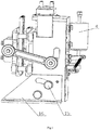
- this embodiment includes a motor lead screw and push block resetting mechanism, an electromagnet resetting mechanism, friction moving/fixed brake lining plate mechanisms, an electromagnetic triggering mechanism and so on, and a connection relationship thereof is as below: the motor lead screw and push block resetting mechanism is mounted between an upper top plate and the latch hook rack, the electromagnet resetting mechanism is connected to the motor lead screw and push block resetting mechanism, the friction moving/fixed brake lining plate mechanisms are mounted on the moving/fixed brake plates, and the electromagnetic triggering mechanism is mounted on the rear side plate.
- the top plate 41 is mounted on an upper part of the steel wire rope brake, two side plates 26 are respectively mounted on the mounting plate 16 at two sides of the steel wire rope brake, the mounting plate 16 is fixedly mounted on a cross beam through bottom mounting holes, and the rear side plate 13 is mounted on the rear side surface (one side opposite to the steel wire rope) of the steel wire rope brake, thereby constituting a frame of the steel wire rope brake.
- a mounting base includes the mounting plate 16, the adjusting screw 15, the fixed pin 14 and so on. After the mounting plate 16 is vertically mounted on the cross beam of an elevator car, the mounting plate 16 is connected into the deflection axle hole 266 of the side plate 26 through the pivot screw 161 on its side, so that the side plate 26 may rotate around the pivot screw 161.
- the side plate 26 After the side plate 26 rotates at an angle of 0-45 degrees, the side plate 26 is locked by connecting the adjusting screw 15 to the deflection locking threaded hole 264 of the side plate 26, then a hole is drilled on the side plate 26 through the pin hole by using an electric drill, then the fixed pin 14 is inserted into the hole, or the mounting plate 16 is welded onto the side plate 26 to prevent the side plate 26 from rotating around the pivot screw 161 in a brake process.
- the adjustment of an angle between the brake plates and the steel wire is achieved by adjusting the mounting angle of the side plate 26, after being adjusted in place, the side plate 26 is fixed.
- the motor lead screw and push block resetting mechanism includes the pin shaft 7, the support rod 8, the tension spring 9, the spring guide holder 10, the support 11, the energy storage spring 17, the sliding axle 18, the spring seat 19, the guide rail 27, the slide block 28, the latch hook 29, the latch hook rack 30, the push block 33, the screw 34, the lead screw 36, the motor 37, the coupled axle-sleeve 38, the motor mounting plate 39, the gear reducer 40 and so on.
- the motor mounting plate 39 is mounted on the top plate 41
- the gear reducer 40 is mounted on the motor mounting plate 39
- the gear reducer 40 is driven by the motor 37 to run
- the external housing of the motor 37 is fixed to the motor mounting plate 39.
- the transmission shaft of the gear reducer 40 is linked with the upper end of the lead screw 36 by connecting with the coupled axle-sleeve 38, the other end of the lead screw 36 forms an external thread and is screwed with the screw 34, and after this end of the lead screw 36 movably penetrates through the push block 33, the lead screw 36 is rotatably positioned on the latch hook rack 30.
- the screw 34 is fixedly mounted on the upper surface of the push block 33, the lead screw 36 is driven by the motor 37 to rotate, and pushes the screw 34 to move through the external thread, and then enables the push block 33 to move.
- the push block 33 is fixedly connected with the slide block 28, the guide rail 27 longitudinally penetrates through the slide block 28 and is in sliding fit with the slide block 28.
- the guide rail 27 is mounted on the rear side plate 13 to form guiding and bearing. While the screw 34 moves, it drives the slide block 28 to move on the guide rail 27.
- the bottom end of the push block 33 forms an inclined plane which directly faces the sliding axle 18 which transversally penetrates through two spring seats 19, and two ends of the sliding axle 18 are respectively placed into an open arc groove 262 formed by the two side plates in a sliding way.
- the energy storage mechanism includes the spring 17, two spring seats 191 and the spring support shaft 192, between the left and the right side plates 26 there is mounted the spring support shaft 192, two ends of the spring support shaft 192 are respectively mounted in the spring seat axle hole 265 of the two side plates, the two spring seats 191 are mounted on the spring support shaft 192, two spring seats 191 are corresponding to two spring seats 19 on the upper part, and between the corresponding spring seats 19 and 191 there is respectively provided with one energy storage spring 17.
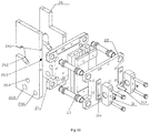
- the fixed brake plate 24 is mounted on the two left and right side plates 26, and the connection structure is as below: each of the two side plates 26 is provided with a pin 263, correspondingly, pin holes are formed on the fixed brake plate 24, first, pin holes on the fixed brake plate 24 are positioned through the pin 263, then are connected through the fixed plate connecting holes 261.
- a plurality of fixed plate connecting holes 261 are respectively formed at a front side edge of each of the two side plates 26, the front side edges of the two side plates 26 fit with the fixed brake plate 24, and the side plates 26 are connected to the fixed brake plate 24 by screws, namely, bolts penetrate through the fixed brake plate 24 and then are screwed into the fixed plate connecting holes 261.
- the latch hook rack 30 is fixedly mounted on an inner side surface of the fixed brake plate 24, the latch hook rack 30 rotatably assembles the latch hook 29 through the pin shaft.
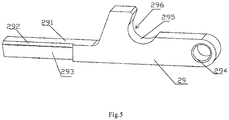
- the latch hook 29 forms the hook trough 296 corresponding to an external wall of the sliding axle 18, which can hook or release the sliding axle 18.
- the other end (outside end) of the latch hook 29 movably stretches out of the rear side plate 13, and this end directly faces the lower end of the impact bar 3.
- the motor 37 starts to run after power is supplied, power is transmitted to the lead screw 36 through an output shaft of the gear reducer 40, then makes screw 34 move on the lead screw 36 to drive the push block 33 to move, the sliding axle 18 is compressed through the inclined surface of the push block 33, the sliding axle 18 implements compression of the energy storage spring 17 by means of the spring seat 19; after the energy storage spring is in place, the latch hook hooks the sliding axle, and the motor reverses to the initial state, thereby implementing the automatic resetting of the steel wire rope brake.
- the electromagnet resetting mechanism includes the pin shaft 7, the support rod 8, the tension spring 9, the spring guide holder 10 and the supports 11.
- a pair of supports 11 are mounted on the rear side plate 13, one support rod 8 that can rotate is mounted on the each support 11, the other end of (outside end) of the support rod 8 forms a pin hole, the pin shaft 7 transversely penetrates through the pin holes of the two support rods 8, one end of the pin shaft 7 positioned outside of one support rod 8 is connected to one end of the tension spring 9, the other end of the tension spring 9 is connected to the outside end of the latch hook 29 to implement resetting of the latch hook 29.
- One section of the pin shaft 7 positioned between the two support rods 8 is connected to the spring guide holder 10 which is connected to the lower end of the impact bar 3, and a part of the impact bar 3 is externally sleeved with the compression spring.
- Two holes are formed on the rear side plate 13, each hole is used for movably up and down penetrating through the inside end of one support rod 8, and the inside end of the support rod 8 bulges upward and directly faces the lower surface of the slide block 28.
- the push block connected with the screw moves to a preset position and comes into contact with the inside end of the support rod; when the push block moves to the preset position, the support rod is pushed to rotate to drive the spring guide holder to move.
- Compression of the spring on the impact bar of the electromagnet is implemented by driving the impact bar to move by the spring guide holder mounted on the impact bar. After compression of the spring is in place, the tension spring pulls the outside end of the latch hook until the sliding axle is locked, at the moment, the motor reverses, and the support restores its initial state due to loss of overhead pressure. In this way, it is implemented the automatic resetting of the power-losing electromagnet.
- the friction moving/fixed brake plate mechanism includes the guiding shaft 23, the fixed brake plate 24, the moving brake plate 22 and the brake lining 35, where the fixed brake plate 24 and the moving brake plate 22 are longitudinally arranged in parallel, opposite surfaces of both are provided with the brake lining 35, and the moving brake plate 22 is the same as the brake lining 35 in assembly structure.
- one side face of the moving brake plate 22 forms two cuboid-shaped recessed parts respectively extending to an upper edge and a lower edge of the moving brake plate 22, two side edges of each of the recessed parts are brake plate table facets 221, and the same side of each of the two recessed parts is provided with a brake lining adjusting hole 20 (an elongated hole is selected in this embodiment so that multiple bolts can be screwed);
- the brake lining 35 forms the recessed part whose edge is a brake lining table facet 351 fitting with the brake plate table facets 221, the brake lining 35 is embedded between the two recessed parts of the moving brake plate 22, and the table facets both come into contact, a width of the table facets 221 at two sides fits with that of the brake lining 35, and both are fixed by screwing bolts into the brake lining adjusting holes 20.
- the brake surface of the brake lining 35 forms a longitudinal arc-shaped groove fitting with an external shape of the steel wire rope, and protrudes out of the side surface of the moving brake plate 22.
- the brake lining 35 on the two brake plates 22 and 24 forms longitudinal arc-shaped grooves corresponding to the steel wire ropes in number, the steel wire rope 25 penetrate the corresponding longitudinal arc-shaped groove, and in a normal state, a clearance is kept between the longitudinal arc-shaped groove and the steel wire rope 25.
- the first brake lining has two arc-shaped grooves
- the second brake lining has three arc-shaped grooves
- five arc-shaped grooves are formed by combination of both, which fits with five steel wires.
- the brake linings are mutually matched and fixed through stepped surfaces. The brake linings are combined to fit with different numbers of steel wire ropes without replacing brake plates.
- Two fixed axle plates 31 are mounted the outer side surface of the moving brake plate 22 through the fastening screw 312, and the adjusting shim 314 is provided between the fixed axle plate 31 and the moving brake plate 22.
- the link arm shaft 32 penetrates through the two fixed axle plates 31 and is fixed by means of the fixed pin 311 to prevent it from rotating.
- the moving brake plate 22 is also provided with two support pins 313 which face an outside of the moving brake plate 22 and are positioned below the link arm shaft 32 to prevent the link arm shaft 32 from sliding down in a brake process by means of the supporting action of the support pins 313.
- the adjusting shim 314 is mounted between the fixed axle plate 31 and the moving brake plate 22 to adjust the height of the sliding axle 18. It is implemented different magnification ratios and spring forces by adjusting the height of the sliding axle 18 to meet requirements for quality of different braking systems.
- the guiding shaft 23 is connected to the fixed brake plate 24 and the moving brake plate 22.
- Each of four corners of the moving brake plate 22 is provided with a hole 222, correspondingly, each of four corners of the fixed brake plate 24 is also provided with a hole, a corresponding hole is connected with the guiding shaft 23, the guiding shaft 23 is fixedly connected with the moving brake plate 22 and is in sliding fit with the fixed brake plate 24, or vice versa, namely, the guiding shaft 23 is in sliding fit with the moving brake plate 22 and is fixedly connected with the fixed brake plate 24.
- the outer side surface of the moving brake plate 22 is fixedly connected with the fixed axle plate 31 which is provided with the link arm shaft 32, two ends of the link arm shaft 32 stretches out of the fixed axle plate 31, and end parts thereof are respectively and rotatably matched with one end of the link arm 21.
- the other end of the link arm 21 is rotatably matched with the sliding axle 18.
- the electromagnetic triggering mechanism includes the electromagnet 4, the impact bar 3, the fixed nut 1, the buffer cushion 2, the electromagnet seat 5 and the fixed plate 6, where the fixed plate 6 is mounted on the rear side plate 13, the electromagnet seat 5 is mounted on the fixed plate 6 through bolts, and the electromagnet 4 is mounted on the electromagnet seat 5.
- the iron core of the electromagnet 4 is linked with the impact bar 3 which moves together with the iron core, and a part of the impact bar 3 is externally sleeved with the compression spring ( FIG. 3 ).
- the spring 4-1 is externally sleeved on a part of the impact bar 3 which longitudinally penetrates through the iron core 4-2 of the electromagnet, the upper end of the impact bar is provided with the buffer cushion 2 and then is fixed by means of the fixed nut 1 to prevent the impact bar 3 from falling off during impact; and the lower end of the impact bar is provided with the buffer cushion 4-4 and then is fixed through the impact screwhead 4-5 to prevent an impact in an ascending resetting process.
- the latch hook 29 forms a latch hook impact plane 291, a safety switch impact plane 292, a latch hook straight slope 293, a latch hook mounting hole 294, a latch hook arc surface 295 and a hook trough 296.
- the latch hook is mounted on the latch hook rack 30 through the latch hook mounting hole 294.
- the latch hook 29 rotates around the latch hook rack 30 to make the straight slope 293 slide so that the hook trough 296 releases the locking of the sliding axle 18, and at the moment, the safety switch impact plane 292 of the latch hook that is moving downward triggers the safety switch 12.
- the latch hook moves upward, the latch hook arc surface 295 comes in contact with the sliding axle 18 so that the hook trough 296 locks the sliding axle 18; when the motor 37 returns back, the sliding axle 18 moves upward under the action of the energy storage spring 17 so that the latch hook arc surface 295 comes in contact with the sliding axle 18, and at the moment, the latch hook is unable to rotate, thereby locking the sliding axle 18.
- the electromagnet 4 When the electromagnet 4 loses power, the electromagnet 4 loses electromagnetic force, driven by the compression spring, the impact bar 3 conducts a downward impact movement and produces an impact effect by means of spring force and self weight, so that the latch hook 29 trips off and releases the compressed energy storage spring 17.
- the safety switch 12 is mounted on the rear side plate 13, when the impact bar 3 of the electromagnet impacts the latch hook 29, the latch hook 29 moves downward to turn on the safety switch 12. Control of the whole elevator is implemented by the safety switch 12 being connected to an elevator safety circuit.
- the safety switch impact plane 292 touches a contact of the safety switch 12 which is connected to a safety circuit of an elevator control system, and the system stops working once the safety circuit is disconnected.
- the automatic resetting steel wire rope brake of the present invention includes: a motor lead screw and push block resetting mechanism, friction moving/fixed brake lining plate mechanisms, an electromagnetic triggering mechanism, an electromagnet automatic resetting mechanism and so on.
- the automatic resetting steel wire rope brake is a safety protection device that updates the function of the original safety device of up-direction over speeding to implement combination of upward overspeed protection and car accidental movement protection.it is improved from electric triggering to power-loss triggering, and elevator upward overspeed protection and car accidental movement protection are achieved by using the motor lead screw and push block resetting mechanism, the friction moving/fixed brake lining plate mechanisms, the electromagnet automatic resetting mechanism and a controller.
- a control signal is outputted to make the electromagnet of the electromagnetic triggering mechanism lose power to trigger the latch hook of the steel wire rope brake to act.
- the motor of the motor lead screw and push block resetting mechanism is energized, the sliding axle, a linkage mechanism and the electromagnet resetting mechanism are compressed by the push block to implement automatic resetting of the energy storage spring, the latch hook and the electromagnet.
- the automatic resetting steel wire rope brake in the present invention is perfect in function, quick in response, stable and controllable, convenient for installation, and low in manufacturing cost, etc.
Landscapes
- Engineering & Computer Science (AREA)
- Mechanical Engineering (AREA)
- Braking Arrangements (AREA)
Claims (15)
- Frein à câble en acier à rétablissement automatique, caractérisé en ce qu'il comprend deux plaques latérales (26), une plaque de frein fixe (24), une plaque de frein mobile (22), une vis de commande du moteur et un mécanisme de rétablissement du bloc de poussée, un mécanisme de rétablissement électromagnétique et un mécanisme de déclenchement électromagnétique ; la plaque de frein fixe (24) et la plaque de frein mobile (22) sont positionnées en parallèle ; un intervalle est maintenu entre les surfaces de blocage opposées de la plaque de frein fixe (24) et de la plaque de frein mobile (22) ; deux côtés de la plaque de frein mobile (22) sont accouplés respectivement et de manière tournante à une extrémité d'un bras d'articulation (21) et la plaque de frein mobile (22) peut exécuter un mouvement de translation vers ou loin de la plaque de frein fixe (24) sous la commande des deux bras d'articulation (21) ; l'autre extrémité de chacun des deux bras d'articulation (21) est accouplée de manière tournante à une extrémité d'un essieu coulissant (18) ; deux extrémités de l'essieu coulissant (18) sont respectivement en accouplement de glissement avec les rainures à arc des deux plaques latérales (26) ; un crochet de fermeture à battant (29) a été prévu ; le crochet de fermeture (29) forme une partie d'accrochage utilisée pour accrocher et bloquer un essieu coulissant (18); une extrémité d'oscillation du crochet de fermeture (29) est déclenchée par un mécanisme de déclenchement électromagnétique ou mécanique pour permettre à l'extrémité d'oscillation de relâcher l'essieu coulissant (18) ; le mécanisme de déclenchement électromagnétique, le crochet de fermeture (29), l'essieu coulissant (18) et la plaque de frein mobile (22) ont été conçus pour pouvoir être rétablis à l'aide de la vis de commande du moteur ; tandis que le rétablissement du bloc de poussée se fait à l'aide du mécanisme de rétablissement à électroaimant ; la vis de commande du moteur et le mécanisme de rétablissement du bloc de poussée comprennent un bloc de poussée (33), une vis (34), une vis de commande (36) et un moteur (37) ; le moteur (37) guide une extrémité supérieure de la vis de commande (36) ; une extrémité inférieure de la vis de commande (36) est reliée de manière tournante à la vis (34) et pénètre de manière mobile à travers le bloc de poussée (33) ; la vis (34) est fixée sur une surface supérieure du bloc de poussée (33) ; et une surface inclinée inférieure du bloc de poussée (33) est orientée directement et s'appuie contre l'essieu coulissant (18).
- Frein à câble en acier à rétablissement automatique, selon la revendication 1, où l'axe coulissant (18) pénètre transversalement à travers un siège de ressort supérieur (19) ; entre les deux plaques latérales (26), on a prévu un arbre de support de ressort (192) sur lequel est monté un siège de ressort inférieur (191) ; le siège de ressort supérieur (19) correspond au siège de ressort inférieur (191) dans les positions supérieure et inférieure ; un ressort d'accumulation d'énergie (17) est prévu entre le siège de ressort supérieur (19) et le siège de ressort inférieur (191) .
- Frein à câble en acier à rétablissement automatique, selon la revendication 1, où le mécanisme de déclenchement électromagnétique comprend un électroaimant (4), une barre d'impact (3), un écrou(l) et un palier amortisseur (2) ; la barre d'impact pénètre dans le sens longitudinal à travers un noyau de fer (4-2) de l'électroaimant (4) ; le noyau de fer (4-2) de l'électroaimant (4) est relié à la barre d'impact (3) ; une partie de la barre d'impact (3) est revêtue à l'extérieur d'un ressort de compression (4-1) ; une extrémité supérieure de la barre d'impact (93) est dotée d'un coussin-tampon (2) et elle est vissée à l'aide de l'écrou (1) ; le coussin-tampon (2) est tourné directement vers une surface supérieure d'un logement externe de l'électroaimant (4-3), et une extrémité inférieure de la barre d' impact (3) est dotée du coussin-tampon (2) et d'une tête de vis d'impact (4-5) qui est orientée directement et s'appuie vers le bas contre l'extrémité oscillante du crochet de fermeture (29).
- Frein à câble en acier à rétablissement automatique, selon la revendication 1, où le bloc de poussée (33) est relié de manière fixe à un bloc coulissant (28), un rail de guidage (27) pénètre dans le sens longitudinal à travers le bloc coulissant (28) et est en accouplement coulissant avec le bloc coulissant (28) ; le mécanisme de rétablissement à électroaimant comprend un arbre de pivot (7), une tige de support (8), un ressort de tension (9), un support de guidage du ressort (10) et un support (11) sur lequel est montée la tige de support (8) qui peut tourner ; une extrémité externe de la tige de support (8) forme un trou pour pivot ; l'arbre de pivot (7) pénètre transversalement à travers le trou de pivot de la tige de support (8) ; une extrémité de l'arbre de pivot (7) est reliée à une extrémité du ressort de tension (9) ; l'autre extrémité du ressort de tension (9) est reliée à l'extrémité d'oscillation du crochet de fermeture (29) ; l'arbre de pivot (7) est aussi relié au support de guidage du ressort (10) qui est relié à une extrémité inférieure de la barre d'impact (3) ; et une extrémité interne de la tige de support (8) est orientée directement vers une surface inférieure du bloc coulissant (28); donc, quand le bloc coulissant (28) se déplace vers le bas, la surface inférieure du bloc coulissant (28) s'appuie contre l'extrémité interne de la tige de support (8) pour faire osciller la tige de support (8) .
- Frein à câble en acier à rétablissement automatique, selon l'une des revendications 1-3, où la plaque de frein fixe (24) est dotée de manière fixe d'une crémaillère à crochet (30) sur laquelle est monté de manière tournante le crochet de fermeture (29) à travers l'arbre de pivot (7).
- Frein à câble en acier à rétablissement automatique, selon l'une des revendications 1-3, où la plaque de frein mobile (22) est reliée de manière fixe à deux plaques d'essieu fixes (31) ; un arbre de bras d'articulation (32) est assemblé entre les deux plaques d'essieu fixes (31) et deux extrémités de l'arbre de bras d'articulation (32) sont accouplées respectivement et de manière tournante à l'extrémité des deux bras d'articulation (21).
- Frein à câble en acier à rétablissement automatique, selon l'une des revendications 1-3, où les deux plaques latérales (26) sont accouplées respectivement et de manière tournante à une plaque de montage (16) à l'aide d'une vis d'articulation (161) ; après avoir réglé un angle de montage, les deux plaques latérales (26) sont reliées de manière fixe à la plaque de montage (16) qui est fixée à une traverse d'une cabine d'ascenseur.
- Frein à câble en acier à rétablissement automatique, selon l'une des revendications 1-3, où une surface latérale externe de la plaque de frein mobile (22) est dotée de deux plaques d'essieu fixes (31) ; un arbre de bras d'articulation (32) pénètre à travers les deux plaques d'essieu fixes (31) et est relié de manière fixe à travers un pivot fixe (311) ; la plaque de frein mobile (22) est aussi dotée d'un pivot de support (313) qui est tourné vers l'extérieur de la plaque de frein mobile (22) et est positionné sous l'arbre de bras d'articulation (32) pour éviter que l'arbre de bras d'articulation (32) glisse vers le bas dans un processus de freinage ; un cale de réglage (314) est prévu entre la plaque d'essieu fixe (24) et la plaque de frein mobile (22).
- Frein à câble en acier à rétablissement automatique, selon la revendication 3, où un interrupteur de sécurité (12) a été prévu ; quand la barre d'impact (3) de l'électroaimant (4) frappe le crochet de fermeture (29) celui-ci se déplace vers le bas pour activer l'interrupteur de sécurité (12) ; le crochet de fermeture (29) est relié à un circuit de sécurité de l'ascenseur à travers l'interrupteur de sécurité (12) ; une surface latérale arrière du frein à câble est dotée d'une plate latérale arrière (13) sur laquelle est montée l'interrupteur de sécurité (12) ; l'électroaimant (4) est monté sur un siège d'électroaimant (5) qui est monté sur une plaque fixe (6) tandis que cette dernière est montée sur la plaque latérale arrière (13).
- Frein à câble en acier à rétablissement automatique, selon l'une des revendications 1-3, où la plaque de frein fixe (24) est montée sur une plaque latérale gauche et une plaque latérale droite ; chacune des deux plaques latérales (26) est dotée d'un pivot ; de manière correspondante, se forment des trous de pivot sur la plaque de frein fixe (24) ; les pivots sont correspondants et reliés de manière fixe aux trous de pivot situés sur la plaque de frein fixe (24) ; une pluralité de trous de raccord de la plaque fixe (261) est respectivement formée sur une bordure latérale avant de chacune des deux plaques latérales (26) ; les bordures latérales avant des deux plaques latérales (26) s' insèrent dans la plaque de frein fixe (24) et les boulons pénètrent à travers la plaque de frein fixe (24) puis ils sont vissés dans les trous de raccord de la plaque fixe (261).
- Frein à câble en acier à rétablissement automatique, selon l'une des revendications 1-3, où la plaque de frein fixe (24) est reliée à la plaque de frein mobile (22) à travers l'arbre de pivot (23).
- Frein à câble en acier à rétablissement automatique, selon la revendication 1 ou 2, où le moteur (37) actionne la vis de commande à travers un réducteur à engrenages (40) et un arbre de transmission du réducteur à engrenages (40) est relié à une extrémité supérieure de la vis de commande à l'aide d'un manchon-essieu accouplé (38).
- Frein à câble en acier à rétablissement automatique, selon l'une des revendications 1-3, où un revêtement de frein (35) est respectivement monté sur la surface de serrage de la plaque de frein fixe (24) et la plaque de frein mobile (22) ; les deux revêtements de frein (35) forment des rainures longitudinales en forme d'arc qui s'adaptent à la forme externe du câble métallique.
- Frein à câble en acier à rétablissement automatique, selon la revendication 13, où la plaque de frein fixe (24) et la plaque de frein mobile (22) forment, vers une surface latérale opposée, deux parties encastrées en forme de cuboïde qui s'étendent respectivement vers une bordure supérieure et une bordure inférieure de la plaque de frein fixe (24) et de la plaque de frein mobile (22) ; deux bordures latérales de chacune des parties encastrées sont des facettes de plateau de plaque de frein (221), et le même côté de chacune des parties encastrées est doté d'un trou de réglage de revêtement de frein (20), de manière correspondante ; le revêtement de frein (35) constitue la partie encastrée dont la bordure est une facette de plateau de revêtement de frein (351) qui s'adapte aux facettes de plateau de plaque de frein (221) ; le revêtement de frein (35) est encastré entre les deux parties encastrées de la plaque de frein fixe (24) et de la plaque de frein mobile (221) ; les facettes de plateau sont au contact l'une de l'autre ; une largeur de la facette de plateau s'adapte, sur les deux côtés, à celle de revêtement de frein (35), et elles sont fixées toutes les deux en serrant les boulons dans les trous de réglage de revêtement de frein (20).
- Frein à câble en acier à rétablissement automatique, selon la revendication 14, où les revêtements de frein (35) sont formés en sélectionnant et en disposant en vertical et en parallèle des revêtements de frein multiples (35), et chaque revêtement de frein (35) est relié de manière fixe à la plaque de frein fixe (24) et à la plaque de frein mobile (22) à l'aide des boulons ; le trou de réglage de revêtement de frein (20) est un trou allongé.
Applications Claiming Priority (3)
| Application Number | Priority Date | Filing Date | Title |
|---|---|---|---|
| CN201420594415.1U CN204138078U (zh) | 2014-10-14 | 2014-10-14 | 钢丝绳制动器 |
| CN201410541362.1A CN104326326B (zh) | 2014-10-14 | 2014-10-14 | 一种自动复位的钢丝绳制动器 |
| PCT/CN2014/093250 WO2016058255A1 (fr) | 2014-10-14 | 2014-12-08 | Frein à câble en acier à réinitialisation automatique |
Publications (3)
| Publication Number | Publication Date |
|---|---|
| EP3208223A1 EP3208223A1 (fr) | 2017-08-23 |
| EP3208223A4 EP3208223A4 (fr) | 2018-06-06 |
| EP3208223B1 true EP3208223B1 (fr) | 2020-06-03 |
Family
ID=55746014
Family Applications (1)
| Application Number | Title | Priority Date | Filing Date |
|---|---|---|---|
| EP14904184.0A Active EP3208223B1 (fr) | 2014-10-14 | 2014-12-08 | Frein à câble en acier à réinitialisation automatique |
Country Status (3)
| Country | Link |
|---|---|
| US (1) | US10266373B2 (fr) |
| EP (1) | EP3208223B1 (fr) |
| WO (1) | WO2016058255A1 (fr) |
Families Citing this family (26)
| Publication number | Priority date | Publication date | Assignee | Title |
|---|---|---|---|---|
| CN108069315B (zh) * | 2016-11-17 | 2023-08-25 | 杭州沪宁电梯部件股份有限公司 | 一种钢丝绳制动器 |
| CN107191515B (zh) * | 2017-05-19 | 2023-03-21 | 中建八局第二建设有限公司 | 一种离心式悬吊钩超速控制装置 |
| CN107991199B (zh) * | 2017-12-28 | 2023-03-24 | 青岛科技大学 | 一种平面涂层抗冲击性能检测装置 |
| WO2019213803A1 (fr) * | 2018-05-07 | 2019-11-14 | G.A.L. Manufacturing Company, Llc | Frein d'urgence d'ascenseur avec sabots |
| CN109898128B (zh) * | 2019-04-23 | 2023-08-29 | 石狮市亿鑫机械设备有限公司 | 一种金属纽扣自动对准悬挂装置及方法 |
| CN110254444B (zh) * | 2019-07-04 | 2024-03-22 | 凯盛重工有限公司 | 一种夹绳装置 |
| CN112305834B (zh) * | 2020-09-23 | 2022-01-14 | 重庆电子工程职业学院 | 一种户外用隐藏式摄像监控装置 |
| CN112357809A (zh) * | 2020-11-28 | 2021-02-12 | 江西惠民电气有限公司 | 一种便携式变电设备起吊装置 |
| CN112879493B (zh) * | 2021-01-25 | 2022-10-14 | 唐山德伯特机械有限公司 | 一种内部角度可调式推动结构 |
| CN112960153B (zh) * | 2021-04-06 | 2023-06-02 | 甘肃润康药业有限公司 | 一种消毒剂罐装设备 |
| CN113472639B (zh) * | 2021-07-16 | 2023-02-28 | 深圳恒天智信科技股份有限公司 | 一种高可靠性工业物联网网关 |
| CN114199699B (zh) * | 2021-11-26 | 2023-12-19 | 中国矿业大学 | 一种钢丝绳冲击快速滑移摩擦装置 |
| CN114382271B (zh) * | 2021-12-02 | 2024-05-28 | 刘小勇 | 一种可用于室外建筑和室内装饰可调节平台 |
| WO2023128896A1 (fr) * | 2021-12-30 | 2023-07-06 | Desird Tasarim Arge Anonim Şirketi | Frein mécanique fixe pour ascenseurs à moteur linéaire |
| CN114172102B (zh) * | 2022-01-24 | 2023-03-28 | 广东鑫源恒业电力线路器材有限公司 | 一种输配电线路用的楔形线夹金具 |
| CN114368009B (zh) * | 2022-03-01 | 2024-07-19 | 苏州艾利特机器人有限公司 | 一种电磁锁机构、制动器及机器人 |
| CN114954538B (zh) * | 2022-05-16 | 2023-06-23 | 江苏徐矿能源股份有限公司张集分公司 | 一种煤矿架空乘人装置落绳自动复位器 |
| EP4289776B1 (fr) * | 2022-06-09 | 2026-01-28 | Otis Elevator Company | Réinitialisation d'un actionneur de sécurité dans un système d'ascenseur |
| US11975945B1 (en) | 2022-11-28 | 2024-05-07 | Otis Elevator Company | Frictionless safety brake actuator |
| EP4378874B1 (fr) | 2022-11-29 | 2025-07-09 | Otis Elevator Company | Actionneur de frein de sécurité d'ascenseur sans frottement |
| CN117430048B (zh) * | 2023-10-13 | 2024-03-29 | 江苏锐金钢丝绳索具有限公司 | 一种用于起重机的钢丝绳索具 |
| CN117214007B (zh) * | 2023-10-18 | 2024-05-07 | 苏州锐驰朗新材料有限公司 | 材料检测落球冲击试验机 |
| CN117386204B (zh) * | 2023-10-31 | 2026-03-20 | 山东启和云梭物流科技有限公司 | 一种智能高效电梯 |
| CN118513501B (zh) * | 2024-07-25 | 2024-11-22 | 天阳新材料(辽宁)有限公司 | 一种快速分离型砂杂质的除杂设备 |
| CN118954233B (zh) * | 2024-10-21 | 2024-12-27 | 江苏赛源机电科技有限公司 | 一种电梯曳引轮制动锁钩 |
| CN119389891B (zh) * | 2024-12-17 | 2025-10-24 | 江苏威尔曼科技有限公司 | 基于物联网的智能化电梯安全管控系统 |
Family Cites Families (9)
| Publication number | Priority date | Publication date | Assignee | Title |
|---|---|---|---|---|
| CN2517718Y (zh) * | 2001-11-23 | 2002-10-23 | 中国建筑科学研究院建筑机械化研究分院 | 电梯曳引绳制动器 |
| KR100454158B1 (ko) * | 2002-04-23 | 2004-10-26 | 김해덕 | 엘리베이터 안전장치 |
| EP1817251B1 (fr) | 2004-12-03 | 2015-03-04 | Otis Elevator Company | Dispositif de securite destine a etre utilise dans un systeme elevateur |
| CN2858602Y (zh) * | 2005-06-09 | 2007-01-17 | 何七牛 | 一种钢丝绳夹绳器 |
| US8511437B2 (en) * | 2008-04-21 | 2013-08-20 | Hollister-Whitney Elevator Corp. | Elevator car brake with shoes actuated by springs coupled to gear drive assembly |
| KR101011024B1 (ko) * | 2010-08-17 | 2011-01-26 | 배후근 | 로프 제동장치 |
| CN103086225B (zh) * | 2012-12-11 | 2016-01-20 | 杭州奥立达电梯有限公司 | 电梯防溜车保护装置 |
| CN203486698U (zh) * | 2013-08-22 | 2014-03-19 | 常熟市琴茂机械有限公司 | 电梯钢丝绳夹绳器 |
| CN203568625U (zh) * | 2013-10-22 | 2014-04-30 | 杭州沪宁电梯配件有限公司 | 组合式电梯夹轨器 |
-
2014
- 2014-12-08 EP EP14904184.0A patent/EP3208223B1/fr active Active
- 2014-12-08 WO PCT/CN2014/093250 patent/WO2016058255A1/fr not_active Ceased
- 2014-12-08 US US15/121,297 patent/US10266373B2/en active Active
Non-Patent Citations (1)
| Title |
|---|
| None * |
Also Published As
| Publication number | Publication date |
|---|---|
| WO2016058255A1 (fr) | 2016-04-21 |
| EP3208223A1 (fr) | 2017-08-23 |
| US10266373B2 (en) | 2019-04-23 |
| EP3208223A4 (fr) | 2018-06-06 |
| US20170217728A1 (en) | 2017-08-03 |
Similar Documents
| Publication | Publication Date | Title |
|---|---|---|
| EP3208223B1 (fr) | Frein à câble en acier à réinitialisation automatique | |
| CN104326326B (zh) | 一种自动复位的钢丝绳制动器 | |
| KR101011024B1 (ko) | 로프 제동장치 | |
| CN1880208B (zh) | 安全制动装置 | |
| JP2019510148A (ja) | 両開きのスライディングプラグドアシステム | |
| CN204138078U (zh) | 钢丝绳制动器 | |
| CN105540378B (zh) | 防止电梯轿厢意外移动的保护系统 | |
| CN104555789B (zh) | 一种钢丝绳制动器 | |
| JP2019502848A (ja) | ねじ駆動制御システム | |
| CN109911739B (zh) | 一种电梯双向安全钳和电梯 | |
| CN107054403B (zh) | 一种机车车辆防溜装置 | |
| EP3335685B1 (fr) | Dispositif de levage ayant un verrou de sécurité et système de libération | |
| CN201908629U (zh) | 抽油机用复合式刹车操纵装置 | |
| CN105540383B (zh) | 防止轿厢意外移动的夹绳器装置 | |
| CN103979380B (zh) | 一种防意外移动的电梯夹绳器 | |
| CN117246904A (zh) | 一种带有应急急刹功能的单轨吊车 | |
| CN211034798U (zh) | 一种用于家用电梯的安全阻挡装置 | |
| CN204342346U (zh) | 钢丝绳制动器 | |
| CN209853517U (zh) | 一种电梯安全钳和电梯 | |
| CN218231435U (zh) | 一种电梯主动防坠落装置 | |
| CN209872044U (zh) | 一种电梯双向安全钳和电梯 | |
| CN214383640U (zh) | 一种电梯用安全钳 | |
| CN108069315B (zh) | 一种钢丝绳制动器 | |
| CN115727082A (zh) | 一种抽油机安全装置 | |
| CN210622605U (zh) | 一种工业门防坠落安全装置 |
Legal Events
| Date | Code | Title | Description |
|---|---|---|---|
| PUAI | Public reference made under article 153(3) epc to a published international application that has entered the european phase |
Free format text: ORIGINAL CODE: 0009012 |
|
| STAA | Information on the status of an ep patent application or granted ep patent |
Free format text: STATUS: REQUEST FOR EXAMINATION WAS MADE |
|
| 17P | Request for examination filed |
Effective date: 20160905 |
|
| AK | Designated contracting states |
Kind code of ref document: A1 Designated state(s): AL AT BE BG CH CY CZ DE DK EE ES FI FR GB GR HR HU IE IS IT LI LT LU LV MC MK MT NL NO PL PT RO RS SE SI SK SM TR |
|
| AX | Request for extension of the european patent |
Extension state: BA ME |
|
| RIN1 | Information on inventor provided before grant (corrected) |
Inventor name: MENG, HONGXING Inventor name: LU, LIMING Inventor name: ZOU, JIACHUM Inventor name: YAO, RONGKANG Inventor name: YANG, DONG |
|
| DAX | Request for extension of the european patent (deleted) | ||
| A4 | Supplementary search report drawn up and despatched |
Effective date: 20180507 |
|
| RIC1 | Information provided on ipc code assigned before grant |
Ipc: B66B 5/24 20060101AFI20180430BHEP |
|
| STAA | Information on the status of an ep patent application or granted ep patent |
Free format text: STATUS: EXAMINATION IS IN PROGRESS |
|
| 17Q | First examination report despatched |
Effective date: 20190219 |
|
| GRAP | Despatch of communication of intention to grant a patent |
Free format text: ORIGINAL CODE: EPIDOSNIGR1 |
|
| STAA | Information on the status of an ep patent application or granted ep patent |
Free format text: STATUS: GRANT OF PATENT IS INTENDED |
|
| INTG | Intention to grant announced |
Effective date: 20200306 |
|
| GRAS | Grant fee paid |
Free format text: ORIGINAL CODE: EPIDOSNIGR3 |
|
| GRAA | (expected) grant |
Free format text: ORIGINAL CODE: 0009210 |
|
| STAA | Information on the status of an ep patent application or granted ep patent |
Free format text: STATUS: THE PATENT HAS BEEN GRANTED |
|
| AK | Designated contracting states |
Kind code of ref document: B1 Designated state(s): AL AT BE BG CH CY CZ DE DK EE ES FI FR GB GR HR HU IE IS IT LI LT LU LV MC MK MT NL NO PL PT RO RS SE SI SK SM TR |
|
| REG | Reference to a national code |
Ref country code: GB Ref legal event code: FG4D |
|
| REG | Reference to a national code |
Ref country code: AT Ref legal event code: REF Ref document number: 1276813 Country of ref document: AT Kind code of ref document: T Effective date: 20200615 Ref country code: CH Ref legal event code: EP |
|
| REG | Reference to a national code |
Ref country code: DE Ref legal event code: R096 Ref document number: 602014066387 Country of ref document: DE |
|
| REG | Reference to a national code |
Ref country code: LT Ref legal event code: MG4D |
|
| PG25 | Lapsed in a contracting state [announced via postgrant information from national office to epo] |
Ref country code: LT Free format text: LAPSE BECAUSE OF FAILURE TO SUBMIT A TRANSLATION OF THE DESCRIPTION OR TO PAY THE FEE WITHIN THE PRESCRIBED TIME-LIMIT Effective date: 20200603 Ref country code: GR Free format text: LAPSE BECAUSE OF FAILURE TO SUBMIT A TRANSLATION OF THE DESCRIPTION OR TO PAY THE FEE WITHIN THE PRESCRIBED TIME-LIMIT Effective date: 20200904 Ref country code: NO Free format text: LAPSE BECAUSE OF FAILURE TO SUBMIT A TRANSLATION OF THE DESCRIPTION OR TO PAY THE FEE WITHIN THE PRESCRIBED TIME-LIMIT Effective date: 20200903 Ref country code: FI Free format text: LAPSE BECAUSE OF FAILURE TO SUBMIT A TRANSLATION OF THE DESCRIPTION OR TO PAY THE FEE WITHIN THE PRESCRIBED TIME-LIMIT Effective date: 20200603 Ref country code: SE Free format text: LAPSE BECAUSE OF FAILURE TO SUBMIT A TRANSLATION OF THE DESCRIPTION OR TO PAY THE FEE WITHIN THE PRESCRIBED TIME-LIMIT Effective date: 20200603 |
|
| REG | Reference to a national code |
Ref country code: NL Ref legal event code: MP Effective date: 20200603 |
|
| PG25 | Lapsed in a contracting state [announced via postgrant information from national office to epo] |
Ref country code: HR Free format text: LAPSE BECAUSE OF FAILURE TO SUBMIT A TRANSLATION OF THE DESCRIPTION OR TO PAY THE FEE WITHIN THE PRESCRIBED TIME-LIMIT Effective date: 20200603 Ref country code: RS Free format text: LAPSE BECAUSE OF FAILURE TO SUBMIT A TRANSLATION OF THE DESCRIPTION OR TO PAY THE FEE WITHIN THE PRESCRIBED TIME-LIMIT Effective date: 20200603 Ref country code: BG Free format text: LAPSE BECAUSE OF FAILURE TO SUBMIT A TRANSLATION OF THE DESCRIPTION OR TO PAY THE FEE WITHIN THE PRESCRIBED TIME-LIMIT Effective date: 20200903 Ref country code: LV Free format text: LAPSE BECAUSE OF FAILURE TO SUBMIT A TRANSLATION OF THE DESCRIPTION OR TO PAY THE FEE WITHIN THE PRESCRIBED TIME-LIMIT Effective date: 20200603 |
|
| REG | Reference to a national code |
Ref country code: AT Ref legal event code: MK05 Ref document number: 1276813 Country of ref document: AT Kind code of ref document: T Effective date: 20200603 |
|
| PG25 | Lapsed in a contracting state [announced via postgrant information from national office to epo] |
Ref country code: AL Free format text: LAPSE BECAUSE OF FAILURE TO SUBMIT A TRANSLATION OF THE DESCRIPTION OR TO PAY THE FEE WITHIN THE PRESCRIBED TIME-LIMIT Effective date: 20200603 Ref country code: NL Free format text: LAPSE BECAUSE OF FAILURE TO SUBMIT A TRANSLATION OF THE DESCRIPTION OR TO PAY THE FEE WITHIN THE PRESCRIBED TIME-LIMIT Effective date: 20200603 |
|
| PG25 | Lapsed in a contracting state [announced via postgrant information from national office to epo] |
Ref country code: CZ Free format text: LAPSE BECAUSE OF FAILURE TO SUBMIT A TRANSLATION OF THE DESCRIPTION OR TO PAY THE FEE WITHIN THE PRESCRIBED TIME-LIMIT Effective date: 20200603 Ref country code: AT Free format text: LAPSE BECAUSE OF FAILURE TO SUBMIT A TRANSLATION OF THE DESCRIPTION OR TO PAY THE FEE WITHIN THE PRESCRIBED TIME-LIMIT Effective date: 20200603 Ref country code: ES Free format text: LAPSE BECAUSE OF FAILURE TO SUBMIT A TRANSLATION OF THE DESCRIPTION OR TO PAY THE FEE WITHIN THE PRESCRIBED TIME-LIMIT Effective date: 20200603 Ref country code: IT Free format text: LAPSE BECAUSE OF FAILURE TO SUBMIT A TRANSLATION OF THE DESCRIPTION OR TO PAY THE FEE WITHIN THE PRESCRIBED TIME-LIMIT Effective date: 20200603 Ref country code: EE Free format text: LAPSE BECAUSE OF FAILURE TO SUBMIT A TRANSLATION OF THE DESCRIPTION OR TO PAY THE FEE WITHIN THE PRESCRIBED TIME-LIMIT Effective date: 20200603 Ref country code: SM Free format text: LAPSE BECAUSE OF FAILURE TO SUBMIT A TRANSLATION OF THE DESCRIPTION OR TO PAY THE FEE WITHIN THE PRESCRIBED TIME-LIMIT Effective date: 20200603 Ref country code: RO Free format text: LAPSE BECAUSE OF FAILURE TO SUBMIT A TRANSLATION OF THE DESCRIPTION OR TO PAY THE FEE WITHIN THE PRESCRIBED TIME-LIMIT Effective date: 20200603 Ref country code: PT Free format text: LAPSE BECAUSE OF FAILURE TO SUBMIT A TRANSLATION OF THE DESCRIPTION OR TO PAY THE FEE WITHIN THE PRESCRIBED TIME-LIMIT Effective date: 20201006 |
|
| PG25 | Lapsed in a contracting state [announced via postgrant information from national office to epo] |
Ref country code: IS Free format text: LAPSE BECAUSE OF FAILURE TO SUBMIT A TRANSLATION OF THE DESCRIPTION OR TO PAY THE FEE WITHIN THE PRESCRIBED TIME-LIMIT Effective date: 20201003 Ref country code: PL Free format text: LAPSE BECAUSE OF FAILURE TO SUBMIT A TRANSLATION OF THE DESCRIPTION OR TO PAY THE FEE WITHIN THE PRESCRIBED TIME-LIMIT Effective date: 20200603 Ref country code: SK Free format text: LAPSE BECAUSE OF FAILURE TO SUBMIT A TRANSLATION OF THE DESCRIPTION OR TO PAY THE FEE WITHIN THE PRESCRIBED TIME-LIMIT Effective date: 20200603 |
|
| REG | Reference to a national code |
Ref country code: DE Ref legal event code: R097 Ref document number: 602014066387 Country of ref document: DE |
|
| PLBE | No opposition filed within time limit |
Free format text: ORIGINAL CODE: 0009261 |
|
| STAA | Information on the status of an ep patent application or granted ep patent |
Free format text: STATUS: NO OPPOSITION FILED WITHIN TIME LIMIT |
|
| PG25 | Lapsed in a contracting state [announced via postgrant information from national office to epo] |
Ref country code: DK Free format text: LAPSE BECAUSE OF FAILURE TO SUBMIT A TRANSLATION OF THE DESCRIPTION OR TO PAY THE FEE WITHIN THE PRESCRIBED TIME-LIMIT Effective date: 20200603 |
|
| 26N | No opposition filed |
Effective date: 20210304 |
|
| PG25 | Lapsed in a contracting state [announced via postgrant information from national office to epo] |
Ref country code: SI Free format text: LAPSE BECAUSE OF FAILURE TO SUBMIT A TRANSLATION OF THE DESCRIPTION OR TO PAY THE FEE WITHIN THE PRESCRIBED TIME-LIMIT Effective date: 20200603 |
|
| PG25 | Lapsed in a contracting state [announced via postgrant information from national office to epo] |
Ref country code: MC Free format text: LAPSE BECAUSE OF FAILURE TO SUBMIT A TRANSLATION OF THE DESCRIPTION OR TO PAY THE FEE WITHIN THE PRESCRIBED TIME-LIMIT Effective date: 20200603 |
|
| REG | Reference to a national code |
Ref country code: BE Ref legal event code: MM Effective date: 20201231 |
|
| PG25 | Lapsed in a contracting state [announced via postgrant information from national office to epo] |
Ref country code: LU Free format text: LAPSE BECAUSE OF NON-PAYMENT OF DUE FEES Effective date: 20201208 Ref country code: IE Free format text: LAPSE BECAUSE OF NON-PAYMENT OF DUE FEES Effective date: 20201208 |
|
| PG25 | Lapsed in a contracting state [announced via postgrant information from national office to epo] |
Ref country code: TR Free format text: LAPSE BECAUSE OF FAILURE TO SUBMIT A TRANSLATION OF THE DESCRIPTION OR TO PAY THE FEE WITHIN THE PRESCRIBED TIME-LIMIT Effective date: 20200603 Ref country code: MT Free format text: LAPSE BECAUSE OF FAILURE TO SUBMIT A TRANSLATION OF THE DESCRIPTION OR TO PAY THE FEE WITHIN THE PRESCRIBED TIME-LIMIT Effective date: 20200603 Ref country code: CY Free format text: LAPSE BECAUSE OF FAILURE TO SUBMIT A TRANSLATION OF THE DESCRIPTION OR TO PAY THE FEE WITHIN THE PRESCRIBED TIME-LIMIT Effective date: 20200603 |
|
| PG25 | Lapsed in a contracting state [announced via postgrant information from national office to epo] |
Ref country code: MK Free format text: LAPSE BECAUSE OF FAILURE TO SUBMIT A TRANSLATION OF THE DESCRIPTION OR TO PAY THE FEE WITHIN THE PRESCRIBED TIME-LIMIT Effective date: 20200603 |
|
| PG25 | Lapsed in a contracting state [announced via postgrant information from national office to epo] |
Ref country code: BE Free format text: LAPSE BECAUSE OF NON-PAYMENT OF DUE FEES Effective date: 20201231 |
|
| P01 | Opt-out of the competence of the unified patent court (upc) registered |
Effective date: 20230601 |
|
| REG | Reference to a national code |
Ref country code: CH Ref legal event code: U11 Free format text: ST27 STATUS EVENT CODE: U-0-0-U10-U11 (AS PROVIDED BY THE NATIONAL OFFICE) Effective date: 20260101 |
|
| PGFP | Annual fee paid to national office [announced via postgrant information from national office to epo] |
Ref country code: GB Payment date: 20251212 Year of fee payment: 12 |
|
| PGFP | Annual fee paid to national office [announced via postgrant information from national office to epo] |
Ref country code: FR Payment date: 20251231 Year of fee payment: 12 |
|
| PGFP | Annual fee paid to national office [announced via postgrant information from national office to epo] |
Ref country code: DE Payment date: 20251231 Year of fee payment: 12 |
|
| PGFP | Annual fee paid to national office [announced via postgrant information from national office to epo] |
Ref country code: CH Payment date: 20260101 Year of fee payment: 12 |