EP3208384A1 - Dispositif de rideau souterrain et procédé de fabrication de rainures dans le sol - Google Patents
Dispositif de rideau souterrain et procédé de fabrication de rainures dans le sol Download PDFInfo
- Publication number
- EP3208384A1 EP3208384A1 EP16156107.1A EP16156107A EP3208384A1 EP 3208384 A1 EP3208384 A1 EP 3208384A1 EP 16156107 A EP16156107 A EP 16156107A EP 3208384 A1 EP3208384 A1 EP 3208384A1
- Authority
- EP
- European Patent Office
- Prior art keywords
- carrier
- slot
- wall device
- removal unit
- yoke
- Prior art date
- Legal status (The legal status is an assumption and is not a legal conclusion. Google has not performed a legal analysis and makes no representation as to the accuracy of the status listed.)
- Granted
Links
- 238000000034 method Methods 0.000 title claims abstract description 19
- 239000002689 soil Substances 0.000 claims abstract description 32
- 238000007789 sealing Methods 0.000 claims abstract description 14
- 239000000463 material Substances 0.000 claims description 10
- 238000005520 cutting process Methods 0.000 claims description 8
- 239000000203 mixture Substances 0.000 claims description 4
- 239000000725 suspension Substances 0.000 description 9
- 238000002156 mixing Methods 0.000 description 3
- 238000009412 basement excavation Methods 0.000 description 2
- 150000001875 compounds Chemical class 0.000 description 2
- 238000009826 distribution Methods 0.000 description 2
- 239000012530 fluid Substances 0.000 description 2
- 239000007788 liquid Substances 0.000 description 2
- 238000003825 pressing Methods 0.000 description 2
- XLYOFNOQVPJJNP-UHFFFAOYSA-N water Substances O XLYOFNOQVPJJNP-UHFFFAOYSA-N 0.000 description 2
- 238000002485 combustion reaction Methods 0.000 description 1
- 230000001419 dependent effect Effects 0.000 description 1
- 230000009969 flowable effect Effects 0.000 description 1
- 239000003673 groundwater Substances 0.000 description 1
- 239000002184 metal Substances 0.000 description 1
- 238000003801 milling Methods 0.000 description 1
- 230000002787 reinforcement Effects 0.000 description 1
- 238000005096 rolling process Methods 0.000 description 1
- 238000003860 storage Methods 0.000 description 1
Images



Classifications
-
- E—FIXED CONSTRUCTIONS
- E02—HYDRAULIC ENGINEERING; FOUNDATIONS; SOIL SHIFTING
- E02F—DREDGING; SOIL-SHIFTING
- E02F3/00—Dredgers; Soil-shifting machines
- E02F3/04—Dredgers; Soil-shifting machines mechanically-driven
- E02F3/18—Dredgers; Soil-shifting machines mechanically-driven with digging wheels turning round an axis, e.g. bucket-type wheels
- E02F3/20—Dredgers; Soil-shifting machines mechanically-driven with digging wheels turning round an axis, e.g. bucket-type wheels with tools that only loosen the material, i.e. mill-type wheels
- E02F3/205—Dredgers; Soil-shifting machines mechanically-driven with digging wheels turning round an axis, e.g. bucket-type wheels with tools that only loosen the material, i.e. mill-type wheels with a pair of digging wheels, e.g. slotting machines
-
- E—FIXED CONSTRUCTIONS
- E02—HYDRAULIC ENGINEERING; FOUNDATIONS; SOIL SHIFTING
- E02D—FOUNDATIONS; EXCAVATIONS; EMBANKMENTS; UNDERGROUND OR UNDERWATER STRUCTURES
- E02D17/00—Excavations; Bordering of excavations; Making embankments
- E02D17/13—Foundation slots or slits; Implements for making these slots or slits
-
- E—FIXED CONSTRUCTIONS
- E02—HYDRAULIC ENGINEERING; FOUNDATIONS; SOIL SHIFTING
- E02D—FOUNDATIONS; EXCAVATIONS; EMBANKMENTS; UNDERGROUND OR UNDERWATER STRUCTURES
- E02D17/00—Excavations; Bordering of excavations; Making embankments
- E02D17/06—Foundation trenches ditches or narrow shafts
- E02D17/12—Back-filling of foundation trenches or ditches
-
- E—FIXED CONSTRUCTIONS
- E02—HYDRAULIC ENGINEERING; FOUNDATIONS; SOIL SHIFTING
- E02D—FOUNDATIONS; EXCAVATIONS; EMBANKMENTS; UNDERGROUND OR UNDERWATER STRUCTURES
- E02D19/00—Keeping dry foundation sites or other areas in the ground
- E02D19/22—Lining sumps in trenches or other foundation pits
-
- E—FIXED CONSTRUCTIONS
- E02—HYDRAULIC ENGINEERING; FOUNDATIONS; SOIL SHIFTING
- E02D—FOUNDATIONS; EXCAVATIONS; EMBANKMENTS; UNDERGROUND OR UNDERWATER STRUCTURES
- E02D5/00—Bulkheads, piles, or other structural elements specially adapted to foundation engineering
- E02D5/18—Bulkheads or similar walls made solely of concrete in situ
- E02D5/187—Bulkheads or similar walls made solely of concrete in situ the bulkheads or walls being made continuously, e.g. excavating and constructing bulkheads or walls in the same process, without joints
-
- E—FIXED CONSTRUCTIONS
- E02—HYDRAULIC ENGINEERING; FOUNDATIONS; SOIL SHIFTING
- E02F—DREDGING; SOIL-SHIFTING
- E02F3/00—Dredgers; Soil-shifting machines
- E02F3/04—Dredgers; Soil-shifting machines mechanically-driven
- E02F3/18—Dredgers; Soil-shifting machines mechanically-driven with digging wheels turning round an axis, e.g. bucket-type wheels
- E02F3/22—Component parts
-
- E—FIXED CONSTRUCTIONS
- E02—HYDRAULIC ENGINEERING; FOUNDATIONS; SOIL SHIFTING
- E02F—DREDGING; SOIL-SHIFTING
- E02F3/00—Dredgers; Soil-shifting machines
- E02F3/04—Dredgers; Soil-shifting machines mechanically-driven
- E02F3/18—Dredgers; Soil-shifting machines mechanically-driven with digging wheels turning round an axis, e.g. bucket-type wheels
- E02F3/22—Component parts
- E02F3/26—Safety or control devices
-
- E—FIXED CONSTRUCTIONS
- E02—HYDRAULIC ENGINEERING; FOUNDATIONS; SOIL SHIFTING
- E02F—DREDGING; SOIL-SHIFTING
- E02F5/00—Dredgers or soil-shifting machines for special purposes
- E02F5/02—Dredgers or soil-shifting machines for special purposes for digging trenches or ditches
- E02F5/08—Dredgers or soil-shifting machines for special purposes for digging trenches or ditches with digging wheels turning round an axis
-
- E—FIXED CONSTRUCTIONS
- E02—HYDRAULIC ENGINEERING; FOUNDATIONS; SOIL SHIFTING
- E02F—DREDGING; SOIL-SHIFTING
- E02F5/00—Dredgers or soil-shifting machines for special purposes
- E02F5/02—Dredgers or soil-shifting machines for special purposes for digging trenches or ditches
- E02F5/10—Dredgers or soil-shifting machines for special purposes for digging trenches or ditches with arrangements for reinforcing trenches or ditches; with arrangements for making or assembling conduits or for laying conduits or cables
- E02F5/104—Dredgers or soil-shifting machines for special purposes for digging trenches or ditches with arrangements for reinforcing trenches or ditches; with arrangements for making or assembling conduits or for laying conduits or cables for burying conduits or cables in trenches under water
- E02F5/109—Dredgers or soil-shifting machines for special purposes for digging trenches or ditches with arrangements for reinforcing trenches or ditches; with arrangements for making or assembling conduits or for laying conduits or cables for burying conduits or cables in trenches under water using rotating digging elements
-
- E—FIXED CONSTRUCTIONS
- E02—HYDRAULIC ENGINEERING; FOUNDATIONS; SOIL SHIFTING
- E02F—DREDGING; SOIL-SHIFTING
- E02F5/00—Dredgers or soil-shifting machines for special purposes
- E02F5/02—Dredgers or soil-shifting machines for special purposes for digging trenches or ditches
- E02F5/12—Dredgers or soil-shifting machines for special purposes for digging trenches or ditches with equipment for back-filling trenches or ditches
-
- E—FIXED CONSTRUCTIONS
- E02—HYDRAULIC ENGINEERING; FOUNDATIONS; SOIL SHIFTING
- E02F—DREDGING; SOIL-SHIFTING
- E02F5/00—Dredgers or soil-shifting machines for special purposes
- E02F5/22—Dredgers or soil-shifting machines for special purposes for making embankments; for back-filling
- E02F5/223—Dredgers or soil-shifting machines for special purposes for making embankments; for back-filling for back-filling
-
- E—FIXED CONSTRUCTIONS
- E02—HYDRAULIC ENGINEERING; FOUNDATIONS; SOIL SHIFTING
- E02F—DREDGING; SOIL-SHIFTING
- E02F5/00—Dredgers or soil-shifting machines for special purposes
- E02F5/30—Auxiliary apparatus, e.g. for thawing, cracking, blowing-up, or other preparatory treatment of the soil
Definitions
- the invention relates to a slot wall device for creating slots in the ground for a slot or sealing wall, with a carrier device on which a Bodenabtragsaku is mounted vertically adjustable, according to the preamble of claim 1.
- the invention further relates to a method for creating slots in the ground with a slot wall device, wherein a soil removal unit is lowered into the ground and soil material is thereby removed, according to the preamble of claim 12.
- Trench wall devices for creating slots in the ground have long been known. As Bodenabtragshim these have a so-called trench wall cutter or a so-called diaphragm wall grab.
- the soil removal unit is usually arranged vertically adjustable on a mast or a boom.
- the masts or extension arms on the carrier devices usually have a height of 15 to 30 m or more.
- Slot or sealing walls can reach depths of 100 m and more. They serve to prevent horizontal water flow, if, for example, an excavation pit is excavated. A sealing wall prevents the lateral inflow of groundwater into the excavation. With sealing walls can also be prevented that water from a landfill or a storage lake seeped laterally into the ground.
- This trench wall device in this case has a rail-guided car with a frame and a boom, which is only slightly higher than a vertical length of a trench wall cutter.
- a cable drum for a carrying cable and connecting cable and a hose reel for a supply hose are mounted close to the ground on the support frame.
- This known diaphragm wall device can be used due to the compact design in spaces with limited height.
- From the EP 2 423 388 A1 shows a method and an apparatus for producing a trench wall, in which a plurality of rod-shaped mixing elements together with cutters, which are arranged on a vertical rod, are descendable vertically along a mast into the ground.
- the vertical bar must have at least a length corresponding to the depth of the slot. Soil material can be processed simultaneously over the entire slot depth via the cutting elements.
- the support and pressing elements are directly connected to the rod-shaped mixing and Abtragsech in the slot to support them laterally from behind.
- the invention has for its object to provide a slot wall device and a method for creating slots in the ground for a slot or sealing wall in the ground, with which a slot or sealing wall can be efficiently created even in very limited space conditions.
- the slot wall device according to the invention is characterized in that a first carrier device and a second carrier device are provided, which are connected to one another via a yoke, and that the Bodenabtragsaku is arranged adjustable below the yoke.
- a basic idea of the invention is, as it were, to support a soil removal unit between two carrier devices on a yoke, which is supported on the two carrier devices.
- the carrier devices can be made relatively small and compact in each case.
- the load can be distributed to the two carrier devices on both sides.
- the carrier devices can be significantly smaller and also formed largely without the usual considerable counterweights at the rear of a single carrier device.
- a particularly compact diaphragm wall device is achieved, which can be used for example in tunnels, under bridges or overpasses and in buildings with ceilings. Due to the good force distribution but even very heavy soil removal units or high diaphragm wall devices can be operated efficiently.
- the two carrier devices are in particular mobile and can be referred to as a carrier vehicle.
- the soil removal unit may in principle be any suitable device, such as a diaphragm wall grab.
- the soil removal unit it is particularly preferred for the soil removal unit to be a trench wall cutter with at least one pair of cutting wheels which can be driven to rotate about horizontal axes of rotation. Particularly preferably, two pairs of cutting wheels are arranged.
- a trench wall cutter with rotating cutting wheels allows a continuous sinking of the slot into the ground.
- Milled soil material can be removed via a suction hose from the slot or remain in the slot, wherein the milled soil material in the slot with a supplied liquid, in particular a concrete suspension, is mixed. The thus formed mixture of soil material and concrete suspension can cure to the desired slot or sealing wall.
- the soil removal unit can be mounted on a linkage, in particular a telescopic linkage on the yoke.
- a particularly compact design is achieved according to a development of the invention in that the Bodenabtragsaku is suspended from at least one support cable.
- the trench wall device may have a height which substantially corresponds to the height of the soil removal unit or is only slightly larger.
- the soil removal unit is connected to at least one supply hose and / or at least one cable.
- Hydraulic fluid, support fluid, concrete suspension or any other gaseous or flowable medium can be supplied to the soil removal unit in the slot via the supply hose (s).
- worn soil material from cutting wheels can be pumped out of the slot via a corresponding disposal hose.
- a corresponding electrical power supply and data lines for controlling the soil removal unit can be provided.
- an internal combustion engine can be provided on at least one of the carrier devices, which supplies all other units, such as hydraulic drives, pumps, etc., to the carrier devices and the soil removal unit with energy.
- an external power supply such as a power cable, may be provided.
- the invention is preferably further developed in that at least one cable drum and at least one hose reel are provided for the at least one carrying cable and / or the at least one cable at least one cable drum.
- the ropes, cables or hoses can be efficiently and compactly stored and operated via the corresponding drums.
- a preferred embodiment of the invention is that the cable drum are rotatably mounted on the first carrier device and the hose reel on the second carrier device. Cable drum and hose reel are thus functionally separated and arranged on different carrier devices. This leads to a uniform weight distribution and facilitates the supply of the trench wall device.
- the preferably U- or C-shaped yoke can be formed as a rigid beam element.
- An improved movability of the slot wall device is achieved according to a development of the invention in that at least one pivot joint is provided on the yoke.
- the swivel joint points while a substantially vertical pivot axis, so that the two carrier devices are mutually adjustable and adjustable. This allows a simplified method of the trench wall device around corners and improves the overall handling of the entire device.
- a further improvement of the mobility is achieved according to an embodiment of the invention in that at least one carrier device has an undercarriage, on which an upper carriage is rotatably mounted.
- both carrier devices have an undercarriage with rotatably mounted superstructure.
- the carrier devices can be designed as a wheeled vehicle or a rail vehicle.
- at least one of the carrier devices is designed as a crawler vehicle with its own drive.
- the carrier device can be self-propelled.
- the other carrier device can passively be moved without its own drive.
- both carrier devices are designed as a tracked vehicle with its own drive.
- the carrier devices at least their undercarriage, formed substantially the same.
- one or both carrier devices are provided with an operating unit.
- the control unit may include a closed cab or a simple control station.
- a mobile operating unit is provided.
- the carrier devices can be moved by one or more operators remotely controlled. This allows a particularly accurate method of carrier equipment, as the operator can be located with a mobile control unit directly at critical positions.
- the mobile operating unit may preferably be a control panel or, in a particularly simple embodiment variant, a tablet computer with a corresponding user interface.
- the connection to the carrier device can be wireless or with a cable respectively.
- the at least one operating unit is preferably releasably attached to the carrier or devices and can be removed by the operator.
- the inventive method is characterized in that the Bodenabtragshow is arranged at a yoke between a first carrier device and a second carrier device, which are connected to each other via the yoke.
- the method can be carried out in particular with the previously described slot wall device. It result in the implementation of the method according to the advantages described above.
- a preferred method variant of the invention is that the slot is carried out in a tunnel, a track or other space with limited ceiling height.
- the process can also be carried out efficiently in channels or other spaces with narrow lateral boundaries.
- a slot or sealing wall is formed, wherein the slots are formed coherently and filled with a curable composition.
- the slots are initially created spaced apart from each other and filled with a curable composition.
- the spaces between the individual diaphragm wall segments are dug and filled with a curable material.
- the individual slots and slot wall segments are connected together and can create a continuous slot or sealing wall.
- the individual slot wall segments can be provided with metal reinforcements as long as the filling compound has not yet cured with a concrete material.
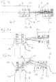
- the trench wall device 10 has a first carrier device 20 and a second carrier device 30, which each have a crawler undercarriage 22, 32.
- a first superstructure 24 is arranged with a frame-like first structure 26 via a pivot bearing 23.
- a second superstructure 34 is rotatably mounted on the second undercarriage 32 of the second carrier vehicle 30 via a pivot bearing 33.
- a rack-like first structure 36 is attached at the second superstructure 34.
- the first carrier vehicle 20 and the second carrier vehicle 30 are connected to each other via a bar-shaped yoke 12.
- a first horizontally projecting yoke member 17 is attached to an upper portion of the first structure 26 of the first carrier vehicle 20, which is coupled via a pivot joint 19 with a vertically directed pivot axis with a second yoke member 18.
- the protruding second yoke member 18 is fixedly secured to an upper portion of the second structure 36 of the second host vehicle 30 in a corresponding manner.
- the yoke 12 forms with the two structures 26, 36 of the two carrier vehicles 20, 30 a gate-like arrangement, with a free or intermediate space in which a soil working unit 50 is suspended.
- the Bodenabtragsaku 50 is formed in the illustrated embodiment as a trench cutter with an approximately rectangular frame 56, at the lower end two pairs of cutting wheels 51, 52 rotatably mounted about horizontal axes of rotation 53, 54 are stored.
- a pump 58 is arranged, via which either a hardening suspension can be injected into the region between the cutting wheel pairs 51, 52 or via which removed soil material can be sucked out of the milling slot with surrounding support liquid.
- hydraulic drives for driving the Fräsradschreibe 51, 52 are attached.
- the pump 58 is connected to a supply hose 16, which is guided via a four-circular roller arch 37 on the yoke 12 to a hose drum 38 is.
- the hose reel 38 is rotatably supported about a horizontal axis of rotation on the second structure 36 of the second carrier vehicle 30.
- the carrying cable 14, together with a plurality of cables 15, which comprise power and data lines, are guided in ribbon form via a rotatable deflection roller 27 on the yoke 12 to a cable drum 28 on the first carrier device 20.
- the cable drum 28 is rotatably mounted in the first structure 26 of the first carrier device 20 about a horizontally directed axis of rotation.
- a slot can be created in the ground, wherein the Bodenabtragsaku 50 is lowered at rotating Fräsradformen 51, 52 in the ground.
- the support cable 14, the cable 15 and the supply hose 16 are tracked by rolling from the cable drum 28 and the hose drum 38.
- the thus forming in the bottom slot is preferably filled with a support suspension, which is introduced via a pump, not shown in the slot. After reaching the final depth of the soil removal unit 50 is pulled back up, with the support cable 14, the cable 15 and the supply hose 16 are rolled up again. Subsequently, the slot wall device 10 is moved further to create another slot.
- the thus created and filled slots form after hardening of the filling compound a continuous slot and sealing wall in the ground.
- the trench wall device 10 according to the invention with the two carrier vehicles 20, 30 can be moved and routed very well even in limited space conditions. So is in accordance with Fig. 3a the slot wall device 10 according to the invention in a tunnel-like main section 5, in which a transverse section 7 opens approximately at right angles. In this case, an approximately rectangular corner region 6 is formed between the walls 8.
- the slot wall device 10 For retraction into the transverse section 7, the slot wall device 10 is moved along the main section 5, wherein the first carrier vehicle 20 and the second carrier vehicle 30 are rectified. As soon as the second carrier vehicle 30 lying in front in the direction of travel is at the level of the middle of the opening transverse stretch 7, the undercarriage 32 of the second carrier vehicle 30 is rotated by corresponding actuation of the crawler tracks by 90 ° to the unchanged superstructure 34, as in Fig. 3b is shown.
- the second carrier vehicle 30 can retract in the direction of the transverse path 7 in this.
- the first undercarriage 22 of the first carrier device 20 remains in its longitudinal orientation to the main line 5.
- the two upper carriage 24, 34 with respect to their respective undercarriage 22, 32 wherein a deflection takes place at the pivot joint 19 on the yoke 12 of the slot wall device 10.
- the first yoke part 17 is increasingly angled to the second yoke part 18, as in the FIGS. 3c to 3f is shown.
- the Fig. 3f shows a rectangular arrangement of the first carrier vehicle 20 to the second carrier vehicle 30, wherein in this right angle Anstellposition the respective uppercarriage 24, 34 are again rectified in their longitudinal orientation to the respective undercarriage 22, 32.
- the second carrier vehicle 30 it is now possible for the second carrier vehicle 30 to travel parallel to the transverse line 7 while the first carrier vehicle 20 is moved further parallel to the longitudinal direction of the main line 5 until the first carrier vehicle 20 is at the level of the middle of the opening transverse line 7, as in FIG Fig. 3g is shown.
- the first superstructure 24 of the first carrier vehicle 20 pivots into the transverse path 7.
Landscapes
- Engineering & Computer Science (AREA)
- Mining & Mineral Resources (AREA)
- Structural Engineering (AREA)
- Civil Engineering (AREA)
- General Engineering & Computer Science (AREA)
- Mechanical Engineering (AREA)
- Life Sciences & Earth Sciences (AREA)
- General Life Sciences & Earth Sciences (AREA)
- Paleontology (AREA)
- Bulkheads Adapted To Foundation Construction (AREA)
Priority Applications (3)
| Application Number | Priority Date | Filing Date | Title |
|---|---|---|---|
| EP16156107.1A EP3208384B1 (fr) | 2016-02-17 | 2016-02-17 | Dispositif de rideau souterrain et procédé de fabrication de rainures dans le sol |
| KR1020170002975A KR101919920B1 (ko) | 2016-02-17 | 2017-01-09 | 지면에 트렌치를 생성하기 위한 다이아프램 벽 장치 및 방법 |
| CN201710041679.2A CN107090861B (zh) | 2016-02-17 | 2017-01-20 | 用于在土地中产生沟槽的隔墙装置和方法 |
Applications Claiming Priority (1)
| Application Number | Priority Date | Filing Date | Title |
|---|---|---|---|
| EP16156107.1A EP3208384B1 (fr) | 2016-02-17 | 2016-02-17 | Dispositif de rideau souterrain et procédé de fabrication de rainures dans le sol |
Publications (2)
| Publication Number | Publication Date |
|---|---|
| EP3208384A1 true EP3208384A1 (fr) | 2017-08-23 |
| EP3208384B1 EP3208384B1 (fr) | 2018-05-23 |
Family
ID=55405162
Family Applications (1)
| Application Number | Title | Priority Date | Filing Date |
|---|---|---|---|
| EP16156107.1A Active EP3208384B1 (fr) | 2016-02-17 | 2016-02-17 | Dispositif de rideau souterrain et procédé de fabrication de rainures dans le sol |
Country Status (3)
| Country | Link |
|---|---|
| EP (1) | EP3208384B1 (fr) |
| KR (1) | KR101919920B1 (fr) |
| CN (1) | CN107090861B (fr) |
Cited By (4)
| Publication number | Priority date | Publication date | Assignee | Title |
|---|---|---|---|---|
| DE202019100284U1 (de) * | 2019-01-18 | 2020-04-22 | Liebherr-Werk Nenzing Gmbh | Trägergerät für eine Schlitzwandfräse sowie Trägerelement hierfür |
| EP3719207A1 (fr) | 2019-04-04 | 2020-10-07 | BAUER Maschinen GmbH | Dispositif de fraisage d'une fouille de fondation et procédé de fraisage d'une fouille dans le sol |
| CN116348643A (zh) * | 2020-10-07 | 2023-06-27 | 包尔机械有限公司 | 土木工程机械以及用于挖土的土木工程方法 |
| EP4269699A1 (fr) * | 2022-04-26 | 2023-11-01 | BAUER Maschinen GmbH | Engin de génie civil |
Families Citing this family (3)
| Publication number | Priority date | Publication date | Assignee | Title |
|---|---|---|---|---|
| EP4053342B1 (fr) | 2021-03-01 | 2023-10-11 | BAUER Maschinen GmbH | Dispositif de fraisage pour parois moulées et procédé de fraisage d'une fente fraisée dans le sol |
| CN113006175A (zh) * | 2021-03-05 | 2021-06-22 | 江西省水利科学院 | 一种螺旋式地下连续墙施工装置及方法 |
| CN121752783A (zh) | 2023-09-11 | 2026-03-27 | 包尔机械有限公司 | 槽壁铣切装置和用于在土地中铣切铣切槽的方法 |
Citations (4)
| Publication number | Priority date | Publication date | Assignee | Title |
|---|---|---|---|---|
| EP0518297B1 (fr) | 1991-06-11 | 1997-02-12 | Bauer Spezialtiefbau GmbH | Dispositif d'excavation et procédé pour la commande de la vitesse d'avance d'un outil d'excavation |
| GB2374884A (en) * | 2001-04-23 | 2002-10-30 | Nuttall Ltd Edmund | Excavation apparatus |
| EP2423388A1 (fr) | 2010-08-30 | 2012-02-29 | Bauer Spezialtiefbau GmbH | Procédé et dispositif de fabrication d'une paroi moulée |
| WO2014199078A1 (fr) * | 2013-06-12 | 2014-12-18 | Soletanche Freyssinet | Procede et installation de fabrication d'une paroi continue dans le sol |
Family Cites Families (3)
| Publication number | Priority date | Publication date | Assignee | Title |
|---|---|---|---|---|
| CN201245856Y (zh) * | 2008-08-12 | 2009-05-27 | 石宗利 | 一种挖桩孔机 |
| JP6047932B2 (ja) * | 2012-06-04 | 2016-12-21 | 株式会社大林組 | 地中連続壁用の掘削機 |
| AU2013237668B2 (en) * | 2012-10-04 | 2017-10-26 | Joy Global Surface Mining Inc | Conduit cartridge |
-
2016
- 2016-02-17 EP EP16156107.1A patent/EP3208384B1/fr active Active
-
2017
- 2017-01-09 KR KR1020170002975A patent/KR101919920B1/ko active Active
- 2017-01-20 CN CN201710041679.2A patent/CN107090861B/zh active Active
Patent Citations (4)
| Publication number | Priority date | Publication date | Assignee | Title |
|---|---|---|---|---|
| EP0518297B1 (fr) | 1991-06-11 | 1997-02-12 | Bauer Spezialtiefbau GmbH | Dispositif d'excavation et procédé pour la commande de la vitesse d'avance d'un outil d'excavation |
| GB2374884A (en) * | 2001-04-23 | 2002-10-30 | Nuttall Ltd Edmund | Excavation apparatus |
| EP2423388A1 (fr) | 2010-08-30 | 2012-02-29 | Bauer Spezialtiefbau GmbH | Procédé et dispositif de fabrication d'une paroi moulée |
| WO2014199078A1 (fr) * | 2013-06-12 | 2014-12-18 | Soletanche Freyssinet | Procede et installation de fabrication d'une paroi continue dans le sol |
Cited By (10)
| Publication number | Priority date | Publication date | Assignee | Title |
|---|---|---|---|---|
| DE202019100284U1 (de) * | 2019-01-18 | 2020-04-22 | Liebherr-Werk Nenzing Gmbh | Trägergerät für eine Schlitzwandfräse sowie Trägerelement hierfür |
| EP3719207A1 (fr) | 2019-04-04 | 2020-10-07 | BAUER Maschinen GmbH | Dispositif de fraisage d'une fouille de fondation et procédé de fraisage d'une fouille dans le sol |
| WO2020200561A1 (fr) * | 2019-04-04 | 2020-10-08 | Bauer Maschinen Gmbh | Dispositif de fraisage de paroi moulée et procédé de fraisage d'une fente de fraisage dans le sol |
| US20220162828A1 (en) * | 2019-04-04 | 2022-05-26 | Bauer Maschinen Gmbh | Trench wall cutting device and method for cutting a cut trench in the ground |
| JP2022536575A (ja) * | 2019-04-04 | 2022-08-18 | バウアー マシーネン ゲーエムベーハー | トレンチ壁カッティング装置及び地中カットトレンチカッティング方法 |
| JP7316374B2 (ja) | 2019-04-04 | 2023-07-27 | バウアー マシーネン ゲーエムベーハー | トレンチ壁カッティング装置及び地中カットトレンチカッティング方法 |
| US12291835B2 (en) * | 2019-04-04 | 2025-05-06 | Bauer Maschinen Gmbh | Trench wall cutting device and method for cutting a cut trench in the ground |
| CN116348643A (zh) * | 2020-10-07 | 2023-06-27 | 包尔机械有限公司 | 土木工程机械以及用于挖土的土木工程方法 |
| JP2023544796A (ja) * | 2020-10-07 | 2023-10-25 | バウアー マシーネン ゲーエムベーハー | 土壌を除去するための、土木機械及び土木工法 |
| EP4269699A1 (fr) * | 2022-04-26 | 2023-11-01 | BAUER Maschinen GmbH | Engin de génie civil |
Also Published As
| Publication number | Publication date |
|---|---|
| KR101919920B1 (ko) | 2019-02-08 |
| EP3208384B1 (fr) | 2018-05-23 |
| CN107090861B (zh) | 2020-02-18 |
| KR20170096943A (ko) | 2017-08-25 |
| CN107090861A (zh) | 2017-08-25 |
Similar Documents
| Publication | Publication Date | Title |
|---|---|---|
| EP3208384B1 (fr) | Dispositif de rideau souterrain et procédé de fabrication de rainures dans le sol | |
| DE69003892T2 (de) | Verfahren zur Ausführung von geraden oder kreisförmigen monolitischen Strukturwänden und Maschine zur Durchführung eines solchen Verfahrens. | |
| DE69112822T2 (de) | Gesteinsfräsradanordnung. | |
| EP1752583A2 (fr) | Fraiseuse à rideau souterrain et procédé pour creuser des tranchées dans le sol | |
| DE102004059943A1 (de) | Vortriebs- oder Gewinnungsmaschine mit Ankerbohr- und -setzeinrichtungen | |
| EP2866992A1 (fr) | Scie à câble | |
| EP2781682B1 (fr) | Petite foreuse | |
| EP3719207B1 (fr) | Dispositif de fraisage d'une fouille de fondation et procédé de fraisage d'une fouille dans le sol | |
| EP4053342B1 (fr) | Dispositif de fraisage pour parois moulées et procédé de fraisage d'une fente fraisée dans le sol | |
| WO2011026632A2 (fr) | Procédé pour faire fonctionner un dispositif d'étançonnement et dispositif d'étançonnement | |
| EP1632609B1 (fr) | Procédée de faire un rideau souterrain | |
| EP0553378B1 (fr) | Dispositif pour former une tranchée dans le sol pendant la construction d'un mur de soutien ou d'étanchéité | |
| EP1167635A1 (fr) | Dispositif pour insérer une conduite | |
| EP3981920B1 (fr) | Dispositif de génie civil et procédé de génie civil permettant d'enlever les sols | |
| DE8701370U1 (de) | Gerät zum Herstellen von Trennfugen in Gebäudewänden und/oder zum Herstellen von Bodenschlitzen | |
| EP3415708A1 (fr) | Dispositif de forage | |
| EP0103706A1 (fr) | Dispositif de soutènement pour l'étayage de tranchées | |
| EP0305835A1 (fr) | Dispositif pour la production des transperçages souterrains | |
| DE2747742A1 (de) | Selbsttaetig verschiebbares arbeitsgeraet fuer einen traktor | |
| EP4357586B1 (fr) | Procédé et dispositif de fraisage pour enlever une couche de sol | |
| DE3446804A1 (de) | Verfahren und vorrichtung zum konsolidieren von tunnelwaenden | |
| WO2025056240A1 (fr) | Dispositif de fraisage de paroi moulée et procédé de fraisage d'une entaille de fraisage dans le sol | |
| DE10207126A1 (de) | Grabenfräse | |
| DE69303450T2 (de) | Teleskopische Führungvorrichtung für ein Baggergerät zum Graben von Tiefgräben mit Frästrommeln | |
| DE102018113955B4 (de) | Baufahrzeug zur Herstellung von Rammpfählen |
Legal Events
| Date | Code | Title | Description |
|---|---|---|---|
| PUAI | Public reference made under article 153(3) epc to a published international application that has entered the european phase |
Free format text: ORIGINAL CODE: 0009012 |
|
| STAA | Information on the status of an ep patent application or granted ep patent |
Free format text: STATUS: REQUEST FOR EXAMINATION WAS MADE |
|
| 17P | Request for examination filed |
Effective date: 20160720 |
|
| AK | Designated contracting states |
Kind code of ref document: A1 Designated state(s): AL AT BE BG CH CY CZ DE DK EE ES FI FR GB GR HR HU IE IS IT LI LT LU LV MC MK MT NL NO PL PT RO RS SE SI SK SM TR |
|
| AX | Request for extension of the european patent |
Extension state: BA ME |
|
| RIC1 | Information provided on ipc code assigned before grant |
Ipc: E02D 17/13 20060101AFI20171120BHEP |
|
| GRAP | Despatch of communication of intention to grant a patent |
Free format text: ORIGINAL CODE: EPIDOSNIGR1 |
|
| STAA | Information on the status of an ep patent application or granted ep patent |
Free format text: STATUS: GRANT OF PATENT IS INTENDED |
|
| INTG | Intention to grant announced |
Effective date: 20180118 |
|
| GRAS | Grant fee paid |
Free format text: ORIGINAL CODE: EPIDOSNIGR3 |
|
| GRAA | (expected) grant |
Free format text: ORIGINAL CODE: 0009210 |
|
| STAA | Information on the status of an ep patent application or granted ep patent |
Free format text: STATUS: THE PATENT HAS BEEN GRANTED |
|
| AK | Designated contracting states |
Kind code of ref document: B1 Designated state(s): AL AT BE BG CH CY CZ DE DK EE ES FI FR GB GR HR HU IE IS IT LI LT LU LV MC MK MT NL NO PL PT RO RS SE SI SK SM TR |
|
| REG | Reference to a national code |
Ref country code: GB Ref legal event code: FG4D Free format text: NOT ENGLISH |
|
| REG | Reference to a national code |
Ref country code: CH Ref legal event code: EP |
|
| REG | Reference to a national code |
Ref country code: IE Ref legal event code: FG4D Free format text: LANGUAGE OF EP DOCUMENT: GERMAN |
|
| REG | Reference to a national code |
Ref country code: AT Ref legal event code: REF Ref document number: 1001619 Country of ref document: AT Kind code of ref document: T Effective date: 20180615 |
|
| REG | Reference to a national code |
Ref country code: DE Ref legal event code: R096 Ref document number: 502016001085 Country of ref document: DE |
|
| REG | Reference to a national code |
Ref country code: NL Ref legal event code: MP Effective date: 20180523 |
|
| REG | Reference to a national code |
Ref country code: LT Ref legal event code: MG4D |
|
| PG25 | Lapsed in a contracting state [announced via postgrant information from national office to epo] |
Ref country code: BG Free format text: LAPSE BECAUSE OF FAILURE TO SUBMIT A TRANSLATION OF THE DESCRIPTION OR TO PAY THE FEE WITHIN THE PRESCRIBED TIME-LIMIT Effective date: 20180823 Ref country code: FI Free format text: LAPSE BECAUSE OF FAILURE TO SUBMIT A TRANSLATION OF THE DESCRIPTION OR TO PAY THE FEE WITHIN THE PRESCRIBED TIME-LIMIT Effective date: 20180523 Ref country code: NO Free format text: LAPSE BECAUSE OF FAILURE TO SUBMIT A TRANSLATION OF THE DESCRIPTION OR TO PAY THE FEE WITHIN THE PRESCRIBED TIME-LIMIT Effective date: 20180823 Ref country code: ES Free format text: LAPSE BECAUSE OF FAILURE TO SUBMIT A TRANSLATION OF THE DESCRIPTION OR TO PAY THE FEE WITHIN THE PRESCRIBED TIME-LIMIT Effective date: 20180523 Ref country code: SE Free format text: LAPSE BECAUSE OF FAILURE TO SUBMIT A TRANSLATION OF THE DESCRIPTION OR TO PAY THE FEE WITHIN THE PRESCRIBED TIME-LIMIT Effective date: 20180523 Ref country code: LT Free format text: LAPSE BECAUSE OF FAILURE TO SUBMIT A TRANSLATION OF THE DESCRIPTION OR TO PAY THE FEE WITHIN THE PRESCRIBED TIME-LIMIT Effective date: 20180523 |
|
| PG25 | Lapsed in a contracting state [announced via postgrant information from national office to epo] |
Ref country code: LV Free format text: LAPSE BECAUSE OF FAILURE TO SUBMIT A TRANSLATION OF THE DESCRIPTION OR TO PAY THE FEE WITHIN THE PRESCRIBED TIME-LIMIT Effective date: 20180523 Ref country code: NL Free format text: LAPSE BECAUSE OF FAILURE TO SUBMIT A TRANSLATION OF THE DESCRIPTION OR TO PAY THE FEE WITHIN THE PRESCRIBED TIME-LIMIT Effective date: 20180523 Ref country code: HR Free format text: LAPSE BECAUSE OF FAILURE TO SUBMIT A TRANSLATION OF THE DESCRIPTION OR TO PAY THE FEE WITHIN THE PRESCRIBED TIME-LIMIT Effective date: 20180523 Ref country code: GR Free format text: LAPSE BECAUSE OF FAILURE TO SUBMIT A TRANSLATION OF THE DESCRIPTION OR TO PAY THE FEE WITHIN THE PRESCRIBED TIME-LIMIT Effective date: 20180824 Ref country code: RS Free format text: LAPSE BECAUSE OF FAILURE TO SUBMIT A TRANSLATION OF THE DESCRIPTION OR TO PAY THE FEE WITHIN THE PRESCRIBED TIME-LIMIT Effective date: 20180523 |
|
| PG25 | Lapsed in a contracting state [announced via postgrant information from national office to epo] |
Ref country code: EE Free format text: LAPSE BECAUSE OF FAILURE TO SUBMIT A TRANSLATION OF THE DESCRIPTION OR TO PAY THE FEE WITHIN THE PRESCRIBED TIME-LIMIT Effective date: 20180523 Ref country code: PL Free format text: LAPSE BECAUSE OF FAILURE TO SUBMIT A TRANSLATION OF THE DESCRIPTION OR TO PAY THE FEE WITHIN THE PRESCRIBED TIME-LIMIT Effective date: 20180523 Ref country code: RO Free format text: LAPSE BECAUSE OF FAILURE TO SUBMIT A TRANSLATION OF THE DESCRIPTION OR TO PAY THE FEE WITHIN THE PRESCRIBED TIME-LIMIT Effective date: 20180523 Ref country code: CZ Free format text: LAPSE BECAUSE OF FAILURE TO SUBMIT A TRANSLATION OF THE DESCRIPTION OR TO PAY THE FEE WITHIN THE PRESCRIBED TIME-LIMIT Effective date: 20180523 Ref country code: SK Free format text: LAPSE BECAUSE OF FAILURE TO SUBMIT A TRANSLATION OF THE DESCRIPTION OR TO PAY THE FEE WITHIN THE PRESCRIBED TIME-LIMIT Effective date: 20180523 Ref country code: DK Free format text: LAPSE BECAUSE OF FAILURE TO SUBMIT A TRANSLATION OF THE DESCRIPTION OR TO PAY THE FEE WITHIN THE PRESCRIBED TIME-LIMIT Effective date: 20180523 |
|
| REG | Reference to a national code |
Ref country code: DE Ref legal event code: R097 Ref document number: 502016001085 Country of ref document: DE |
|
| PG25 | Lapsed in a contracting state [announced via postgrant information from national office to epo] |
Ref country code: SM Free format text: LAPSE BECAUSE OF FAILURE TO SUBMIT A TRANSLATION OF THE DESCRIPTION OR TO PAY THE FEE WITHIN THE PRESCRIBED TIME-LIMIT Effective date: 20180523 |
|
| PLBE | No opposition filed within time limit |
Free format text: ORIGINAL CODE: 0009261 |
|
| STAA | Information on the status of an ep patent application or granted ep patent |
Free format text: STATUS: NO OPPOSITION FILED WITHIN TIME LIMIT |
|
| 26N | No opposition filed |
Effective date: 20190226 |
|
| REG | Reference to a national code |
Ref country code: CH Ref legal event code: PL |
|
| PG25 | Lapsed in a contracting state [announced via postgrant information from national office to epo] |
Ref country code: MC Free format text: LAPSE BECAUSE OF FAILURE TO SUBMIT A TRANSLATION OF THE DESCRIPTION OR TO PAY THE FEE WITHIN THE PRESCRIBED TIME-LIMIT Effective date: 20180523 Ref country code: LU Free format text: LAPSE BECAUSE OF NON-PAYMENT OF DUE FEES Effective date: 20190217 |
|
| REG | Reference to a national code |
Ref country code: BE Ref legal event code: MM Effective date: 20190228 |
|
| REG | Reference to a national code |
Ref country code: IE Ref legal event code: MM4A |
|
| PG25 | Lapsed in a contracting state [announced via postgrant information from national office to epo] |
Ref country code: AL Free format text: LAPSE BECAUSE OF FAILURE TO SUBMIT A TRANSLATION OF THE DESCRIPTION OR TO PAY THE FEE WITHIN THE PRESCRIBED TIME-LIMIT Effective date: 20180523 |
|
| PG25 | Lapsed in a contracting state [announced via postgrant information from national office to epo] |
Ref country code: CH Free format text: LAPSE BECAUSE OF NON-PAYMENT OF DUE FEES Effective date: 20190228 Ref country code: LI Free format text: LAPSE BECAUSE OF NON-PAYMENT OF DUE FEES Effective date: 20190228 |
|
| PG25 | Lapsed in a contracting state [announced via postgrant information from national office to epo] |
Ref country code: IE Free format text: LAPSE BECAUSE OF NON-PAYMENT OF DUE FEES Effective date: 20190217 |
|
| PG25 | Lapsed in a contracting state [announced via postgrant information from national office to epo] |
Ref country code: BE Free format text: LAPSE BECAUSE OF NON-PAYMENT OF DUE FEES Effective date: 20190228 |
|
| PG25 | Lapsed in a contracting state [announced via postgrant information from national office to epo] |
Ref country code: TR Free format text: LAPSE BECAUSE OF FAILURE TO SUBMIT A TRANSLATION OF THE DESCRIPTION OR TO PAY THE FEE WITHIN THE PRESCRIBED TIME-LIMIT Effective date: 20180523 |
|
| PG25 | Lapsed in a contracting state [announced via postgrant information from national office to epo] |
Ref country code: PT Free format text: LAPSE BECAUSE OF FAILURE TO SUBMIT A TRANSLATION OF THE DESCRIPTION OR TO PAY THE FEE WITHIN THE PRESCRIBED TIME-LIMIT Effective date: 20180924 Ref country code: MT Free format text: LAPSE BECAUSE OF FAILURE TO SUBMIT A TRANSLATION OF THE DESCRIPTION OR TO PAY THE FEE WITHIN THE PRESCRIBED TIME-LIMIT Effective date: 20180523 |
|
| PG25 | Lapsed in a contracting state [announced via postgrant information from national office to epo] |
Ref country code: CY Free format text: LAPSE BECAUSE OF FAILURE TO SUBMIT A TRANSLATION OF THE DESCRIPTION OR TO PAY THE FEE WITHIN THE PRESCRIBED TIME-LIMIT Effective date: 20180523 |
|
| PG25 | Lapsed in a contracting state [announced via postgrant information from national office to epo] |
Ref country code: IS Free format text: LAPSE BECAUSE OF FAILURE TO SUBMIT A TRANSLATION OF THE DESCRIPTION OR TO PAY THE FEE WITHIN THE PRESCRIBED TIME-LIMIT Effective date: 20180923 |
|
| PG25 | Lapsed in a contracting state [announced via postgrant information from national office to epo] |
Ref country code: HU Free format text: LAPSE BECAUSE OF FAILURE TO SUBMIT A TRANSLATION OF THE DESCRIPTION OR TO PAY THE FEE WITHIN THE PRESCRIBED TIME-LIMIT; INVALID AB INITIO Effective date: 20160217 |
|
| PG25 | Lapsed in a contracting state [announced via postgrant information from national office to epo] |
Ref country code: SI Free format text: LAPSE BECAUSE OF FAILURE TO SUBMIT A TRANSLATION OF THE DESCRIPTION OR TO PAY THE FEE WITHIN THE PRESCRIBED TIME-LIMIT Effective date: 20180523 |
|
| PG25 | Lapsed in a contracting state [announced via postgrant information from national office to epo] |
Ref country code: MK Free format text: LAPSE BECAUSE OF FAILURE TO SUBMIT A TRANSLATION OF THE DESCRIPTION OR TO PAY THE FEE WITHIN THE PRESCRIBED TIME-LIMIT Effective date: 20180523 |
|
| PGFP | Annual fee paid to national office [announced via postgrant information from national office to epo] |
Ref country code: DE Payment date: 20250220 Year of fee payment: 10 |
|
| PGFP | Annual fee paid to national office [announced via postgrant information from national office to epo] |
Ref country code: AT Payment date: 20250221 Year of fee payment: 10 |
|
| PGFP | Annual fee paid to national office [announced via postgrant information from national office to epo] |
Ref country code: FR Payment date: 20250226 Year of fee payment: 10 |
|
| PGFP | Annual fee paid to national office [announced via postgrant information from national office to epo] |
Ref country code: IT Payment date: 20250213 Year of fee payment: 10 Ref country code: GB Payment date: 20250225 Year of fee payment: 10 |