EP3208402A1 - Dach- oder fassadenelement in gestalt eines sandwichartig aufgebauten dämmpaneels - Google Patents
Dach- oder fassadenelement in gestalt eines sandwichartig aufgebauten dämmpaneels Download PDFInfo
- Publication number
- EP3208402A1 EP3208402A1 EP16202354.3A EP16202354A EP3208402A1 EP 3208402 A1 EP3208402 A1 EP 3208402A1 EP 16202354 A EP16202354 A EP 16202354A EP 3208402 A1 EP3208402 A1 EP 3208402A1
- Authority
- EP
- European Patent Office
- Prior art keywords
- roof
- facade element
- insulating layer
- cover plate
- outer cover
- Prior art date
- Legal status (The legal status is an assumption and is not a legal conclusion. Google has not performed a legal analysis and makes no representation as to the accuracy of the status listed.)
- Granted
Links
Images


Classifications
-
- E—FIXED CONSTRUCTIONS
- E04—BUILDING
- E04C—STRUCTURAL ELEMENTS; BUILDING MATERIALS
- E04C2/00—Building elements of relatively thin form for the construction of parts of buildings, e.g. sheet materials, slabs, or panels
- E04C2/02—Building elements of relatively thin form for the construction of parts of buildings, e.g. sheet materials, slabs, or panels characterised by specified materials
- E04C2/26—Building elements of relatively thin form for the construction of parts of buildings, e.g. sheet materials, slabs, or panels characterised by specified materials composed of materials covered by two or more of groups E04C2/04, E04C2/08, E04C2/10 or of materials covered by one of these groups with a material not specified in one of the groups
- E04C2/284—Building elements of relatively thin form for the construction of parts of buildings, e.g. sheet materials, slabs, or panels characterised by specified materials composed of materials covered by two or more of groups E04C2/04, E04C2/08, E04C2/10 or of materials covered by one of these groups with a material not specified in one of the groups at least one of the materials being insulating
- E04C2/288—Building elements of relatively thin form for the construction of parts of buildings, e.g. sheet materials, slabs, or panels characterised by specified materials composed of materials covered by two or more of groups E04C2/04, E04C2/08, E04C2/10 or of materials covered by one of these groups with a material not specified in one of the groups at least one of the materials being insulating composed of insulating material and concrete, stone or stone-like material
-
- E—FIXED CONSTRUCTIONS
- E04—BUILDING
- E04C—STRUCTURAL ELEMENTS; BUILDING MATERIALS
- E04C2/00—Building elements of relatively thin form for the construction of parts of buildings, e.g. sheet materials, slabs, or panels
- E04C2/54—Slab-like translucent elements
-
- E—FIXED CONSTRUCTIONS
- E04—BUILDING
- E04D—ROOF COVERINGS; SKY-LIGHTS; GUTTERS; ROOF-WORKING TOOLS
- E04D3/00—Roof covering by making use of flat or curved slabs or stiff sheets
- E04D3/35—Roofing slabs or stiff sheets comprising two or more layers, e.g. for insulation
- E04D3/351—Roofing slabs or stiff sheets comprising two or more layers, e.g. for insulation at least one of the layers being composed of insulating material, e.g. fibre or foam material
- E04D3/352—Roofing slabs or stiff sheets comprising two or more layers, e.g. for insulation at least one of the layers being composed of insulating material, e.g. fibre or foam material at least one insulating layer being located between non-insulating layers, e.g. double skin slabs or sheets
-
- E—FIXED CONSTRUCTIONS
- E04—BUILDING
- E04F—FINISHING WORK ON BUILDINGS, e.g. STAIRS, FLOORS
- E04F13/00—Coverings or linings, e.g. for walls or ceilings
- E04F13/07—Coverings or linings, e.g. for walls or ceilings composed of covering or lining elements; Sub-structures therefor; Fastening means therefor
- E04F13/08—Coverings or linings, e.g. for walls or ceilings composed of covering or lining elements; Sub-structures therefor; Fastening means therefor composed of a plurality of similar covering or lining elements
- E04F13/0875—Coverings or linings, e.g. for walls or ceilings composed of covering or lining elements; Sub-structures therefor; Fastening means therefor composed of a plurality of similar covering or lining elements having a basic insulating layer and at least one covering layer
- E04F13/0876—Coverings or linings, e.g. for walls or ceilings composed of covering or lining elements; Sub-structures therefor; Fastening means therefor composed of a plurality of similar covering or lining elements having a basic insulating layer and at least one covering layer the covering layer comprising mutual alignment or interlocking means
-
- F—MECHANICAL ENGINEERING; LIGHTING; HEATING; WEAPONS; BLASTING
- F24—HEATING; RANGES; VENTILATING
- F24S—SOLAR HEAT COLLECTORS; SOLAR HEAT SYSTEMS
- F24S20/00—Solar heat collectors specially adapted for particular uses or environments
- F24S20/60—Solar heat collectors integrated in fixed constructions, e.g. in buildings
- F24S20/66—Solar heat collectors integrated in fixed constructions, e.g. in buildings in the form of facade constructions, e.g. wall constructions
-
- E—FIXED CONSTRUCTIONS
- E04—BUILDING
- E04F—FINISHING WORK ON BUILDINGS, e.g. STAIRS, FLOORS
- E04F13/00—Coverings or linings, e.g. for walls or ceilings
- E04F13/07—Coverings or linings, e.g. for walls or ceilings composed of covering or lining elements; Sub-structures therefor; Fastening means therefor
- E04F13/08—Coverings or linings, e.g. for walls or ceilings composed of covering or lining elements; Sub-structures therefor; Fastening means therefor composed of a plurality of similar covering or lining elements
- E04F13/0869—Coverings or linings, e.g. for walls or ceilings composed of covering or lining elements; Sub-structures therefor; Fastening means therefor composed of a plurality of similar covering or lining elements having conduits for fluids
-
- E—FIXED CONSTRUCTIONS
- E04—BUILDING
- E04F—FINISHING WORK ON BUILDINGS, e.g. STAIRS, FLOORS
- E04F13/00—Coverings or linings, e.g. for walls or ceilings
- E04F13/07—Coverings or linings, e.g. for walls or ceilings composed of covering or lining elements; Sub-structures therefor; Fastening means therefor
- E04F13/08—Coverings or linings, e.g. for walls or ceilings composed of covering or lining elements; Sub-structures therefor; Fastening means therefor composed of a plurality of similar covering or lining elements
- E04F13/14—Coverings or linings, e.g. for walls or ceilings composed of covering or lining elements; Sub-structures therefor; Fastening means therefor composed of a plurality of similar covering or lining elements stone or stone-like materials, e.g. ceramics concrete; of glass or with an outer layer of stone or stone-like materials or glass
- E04F13/145—Coverings or linings, e.g. for walls or ceilings composed of covering or lining elements; Sub-structures therefor; Fastening means therefor composed of a plurality of similar covering or lining elements stone or stone-like materials, e.g. ceramics concrete; of glass or with an outer layer of stone or stone-like materials or glass with an outer layer of glass
-
- Y—GENERAL TAGGING OF NEW TECHNOLOGICAL DEVELOPMENTS; GENERAL TAGGING OF CROSS-SECTIONAL TECHNOLOGIES SPANNING OVER SEVERAL SECTIONS OF THE IPC; TECHNICAL SUBJECTS COVERED BY FORMER USPC CROSS-REFERENCE ART COLLECTIONS [XRACs] AND DIGESTS
- Y02—TECHNOLOGIES OR APPLICATIONS FOR MITIGATION OR ADAPTATION AGAINST CLIMATE CHANGE
- Y02B—CLIMATE CHANGE MITIGATION TECHNOLOGIES RELATED TO BUILDINGS, e.g. HOUSING, HOUSE APPLIANCES OR RELATED END-USER APPLICATIONS
- Y02B10/00—Integration of renewable energy sources in buildings
- Y02B10/20—Solar thermal
-
- Y—GENERAL TAGGING OF NEW TECHNOLOGICAL DEVELOPMENTS; GENERAL TAGGING OF CROSS-SECTIONAL TECHNOLOGIES SPANNING OVER SEVERAL SECTIONS OF THE IPC; TECHNICAL SUBJECTS COVERED BY FORMER USPC CROSS-REFERENCE ART COLLECTIONS [XRACs] AND DIGESTS
- Y02—TECHNOLOGIES OR APPLICATIONS FOR MITIGATION OR ADAPTATION AGAINST CLIMATE CHANGE
- Y02E—REDUCTION OF GREENHOUSE GAS [GHG] EMISSIONS, RELATED TO ENERGY GENERATION, TRANSMISSION OR DISTRIBUTION
- Y02E10/00—Energy generation through renewable energy sources
- Y02E10/40—Solar thermal energy, e.g. solar towers
Definitions
- the invention relates to a construction element, and in particular a roof or facade element in the form of a sandwich-type Dämmpaneels with an optimized outer surface.
- Insulating panels of the generic type are in particular those which are used for use in the construction sector, in particular for roofing and facade cladding.
- Such known from the prior art Dämmpaneele usually consist of two outer plates made of sheet metal or PVC, sandwiched between which is an insulating layer, for example, polyurethane foam.
- Such a Dämmpaneel is for example in the WO 2004/009929 A1 described.
- the known from this prior art panel consists of a pair of sheets which are sandwiched together with intermediate insulating layer.
- the two cover plates usually serve to give the sandwich-like Dämmpaneel a high mechanical strength and design the entire sandwich element weatherproof and as insensitive to mechanical influences.
- Most of the two outer layers are glued to the insulating layer with the aid of an adhesive.
- the conventional Dämmpaneele known from construction technology have the disadvantage that they can indeed produce relatively cheap, but their application is usually limited to commercial halls, especially warehouses or factory buildings.
- the reason for this is, on the one hand, that insulating panels from the construction sector of the known type - if at all - are difficult to incorporate into the architecture of, for example, a residential or office building.
- a further disadvantage in this context is that the conventional insulation panels known from the construction sector do not offer any possibilities of exposure to the inside or sight to the outside, which however is increasingly required, in particular in the field of building construction.
- the invention has for its object to provide a construction element, in particular in the form of a sandwich-like Dämmpaneels or in the form of a sandwich-like facade panel, which can be relatively cheaply produced, at the same time a sound and heat insulation should be achieved comparable with the values at a corresponding industrial panel.
- the construction element is to be suitable for the construction of buildings and should, if necessary, allow the desired in object construction light transmission.
- a roof or facade element is given in the form of a sandwich-mounted Dämmpaneels, said Dämmpaneel having an insulating layer with an outwardly facing first top surface, an inwardly facing second top surface and having a connecting the two top surfaces circumferential surface.
- an integral, in particular monolithic, outer cover plate is provided, in particular made of glass or a vitreous material.
- the outer cover plate is dimensioned and arranged on the first cover surface of the insulating layer such that the first cover surface of the insulating layer is completely covered by the outer cover plate.
- the Dämmpaneel a trained at least partially its peripheral edge region and not from the outside Visible area, which serves to record construction elements concealed.
- the outer cover plate is made of glass, a vitreous material or an inorganic material.
- the outer cover plate may consist of all materials suitable for construction, such as lightweight concrete, stone or natural stone. It is also conceivable to use a metal sandwich plate for this purpose.
- the sandwich-like Dämmpaneel may have at least at first glance structurally certain similarities with the prior art industrial panels, which come as facade panels for commercial halls etc. used. Because as well as conventional industrial panels, the Dämmpaneel invention has an insulating layer in particular of mineral or erölbasêtm insulation. According to developments of the Dämmpaneels invention further first and second cover plates are used, the sandwich close the insulating layer, wherein the cover plate are formed of a material relative to the material of the insulating hard material.
- the cover plates are formed from metal or a metal sandwich.
- other materials for the cover plates in question such as gypsum board boards, cement-bonded boards, natural stone or ornamental panels.
- the first cover layer is made of a material which is different from the material of the second cover layer.
- the insulating layer of the sandwich-like Dämmpaneels has an outwardly facing first top surface and an inwardly facing second top surface.
- the one-piece, in particular monolithic outer cover plate of glass or a glassy material is essential to the invention.
- the outer cover plate is full area on the outwardly facing first Cover surface of the insulating layer arranged and connected to the corresponding cover layer.
- connection between the outer cover plate and the outwardly facing first cover surface of the insulating layer can take place via a multiplicity of holding plates or holding points.
- the holding plates / holding points can for example consist of a light metal, in particular aluminum, and preferably have a thickness of at least 4 mm, preferably at least 6 mm, and a base area of not more than 50 ⁇ 50 mm 2 and preferably not more than 30 ⁇ 30 mm 2 .
- the holding plates by means of which the outer cover plate is connected to the outwardly facing first cover surface of the insulating layer, to be connected in a material-bonded manner to an inwardly facing surface of the outer cover plate.
- the cohesive connection can be realized, for example, with the aid of an adhesive, in particular a silicone rubber-based adhesive. Conceivable in this context, it would also be if the cohesive connection is realized by means of a double-sided adhesive tape.
- the holding plates via which the outer cover plate is connected to the outwardly facing first cover surface of the insulating layer, is connected via a screw or rivet connection with the corresponding cover surface. Accordingly, it is particularly conceivable that for the production of the roof or facade element according to the invention, first the holding plates are connected to the corresponding top surface of the insulating layer, then an adhesive is applied to the holding plates to the cohesive connection of the outer cover plate with the already with the corresponding deck surface of the insulating layer connected holding plates to realize.
- the outer cover plate is not connected to the first cover plate or the top surface of the insulating layer via retaining plates, but rather via a line-shaped adhesive bond in particular.
- This bonding is, in particular, a silicone-based bond.
- the outer cover plate can be arranged in a particularly easy to implement yet effective manner over the entire surface on the outwardly facing first cover surface of the insulating layer and fix it there.
- corresponding holding plates which are arranged in the finished assembled state of the roof or facade element between the outer cover plate and the corresponding top surface of the insulating layer, there is (consciously) an air gap between the outer cover plate and the corresponding top surface of the insulating layer, which allows a ventilation of the roof or facade element, so as to prevent unwanted condensation, in particular on the inner surface of the outer cover plate.
- a cover is provided to cover at least the upper longitudinal edge of the roof or facade element and the (unwanted) penetration of moisture and / or dirt in the air gap between the outer cover plate and the first top surface of the To prevent insulation.
- a Attikablech to realize the cover at least the upper edge of the roof / facade element.
- an area formed at least partially in the peripheral edge region of the insulating panel and not visible from the outside is provided, which serves for the concealed receiving of construction elements.
- this area, which is not visible from the outside is formed in at least two opposite sides of the insulating panel, and more preferably this area, which is not visible from the outside, is designed as a region surrounding the insulating panel.
- the area, which is not visible from the outside should be dimensioned and designed in such a way that a frame construction, in particular a frame construction of a window element arranged adjacent to the roof element or façade element, can be accommodated in the non-visible area.
- the area, which is not visible from the outside is dimensioned and designed in such a way that a supporting profile can be concealed in the non-visible area. This support profile may be necessary to ensure the necessary load capacity of the roof / façade element.
- the area which is not visible from the outside, has a depth which rebounds from the edge region of the insulating panel, which depth is equal to or greater than the thickness or thickness of the insulating layer.
- two adjacent roof / facade elements can be arranged at an angle, wherein the then forming corner region is formed to the outside only from the outer cover plate.
- this relates to an arrangement with at least one roof or facade element of the type described above and with a window element arranged adjacent to this roof or facade element, which has a frame construction and a wing construction which can be moved relative to the frame construction Frame structure is added in the non-visible from the outside area of the roof or facade element.
- a window sash which is rotated to open relative to the frame structure mechanically linearly shifted and / or pivoted.
- the invention relates to a facade element 100 or structural element for forming a facade or a roof.
- the facade can be formed, for example, by arranging several adjacent construction elements / facade elements 100, which are designed in the form of sandwich-mounted Dämmpaneelen with intermediate support profiles.
- Insulating panels for use in the construction sector, in particular for roofing and facade cladding are known, at least in principle, generally from the prior art. They usually consist of two outer plates made of sheet steel or aluminum, sandwiched between which is an insulating layer, such as polyurethane foam or mineral wool. In the insulating panels used in construction technology, the two cover plates usually serve to give the sandwich-like Dämmpaneel a high mechanical strength and design the entire sandwich element weatherproof and as insensitive to mechanical influences.
- Sandwich elements in the sense of the present disclosure are plate structures whose outer shells are connected to each other in a shear-resistant manner via a core. The tensile and compressive forces are relatively evenly distributed in the plates.
- the two outer layers are glued to the insulating layer with the aid of an adhesive.
- the installation of these elements can be done either vertically or horizontally.
- the elements usually have a width of about 1 to 1.2 m.
- the length of these elements can be up to 15 m.
- the possible span is influenced primarily by the two factors "load bearing capacity of the panel” and "external actions".
- the load-bearing capacity of the panel is determined by the nature of the core (insulation layer) through which Thickness of the panel and the thickness of the outer panels influenced.
- the external influences are primarily wind loads acting on the panel. The amount of wind loads depends heavily on the installation site and are regulated in standards or guidelines.
- an additional supporting profile is introduced between two adjacent sandwich elements.
- the support profile is shaped so that it fits exactly into the profile contours, i. the non-visible area 10, the standard elements fits.
- the support profile can be made narrower or wider.
- the support profile may also have an extension on the outside or on the inside.
- the standard panels can be combined with this profile without modification.
- the support profile may consist of a thermally-separated metal-plastic composite profile.
- the support profile can also be made of a monolithic material with low thermal conductivity, such as e.g. consist of a glass fiber reinforced plastic.
- the support profile can fulfill even more functions.
- the profile can be used on the outside or inside to attach additional components, such as company logos, lighting, or other products.
- additional components such as company logos, lighting, or other products.
- the profile can also be understood with lighting means that allow inside or outside direct or indirect lighting.
- the sandwich panel can be stretched over larger spans. Furthermore, so that sandwich elements can be installed, for example, have openings or openings, and are thus weakened statically.
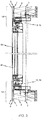
- FIG. 2 shows a top view of a wall system with cladding elements 100 in accordance with exemplary embodiments of the present invention.
- FIG. 3 shows a sectional view taken along the line AA in FIG. 2 ,
- the wall system has a first facade element 100 according to an exemplary embodiment of the invention with a window element 200 arranged adjacent to the facade element 100.
- the window member 200 comprises a frame structure 50 and a relative to the frame structure 50 movable (slidable, pivotable and / or rotatable) wing construction 60 has.
- the frame construction 50 is accommodated in a region 10 of the facade element 100 which is not visible from the outside.
- a second facade element 300 Parallel to the first facade element 100 and the window element 200 arranged adjacent to the facade element 100, a second facade element 300 is provided which has a length which is greater than, for example, the combined length of the first facade element 100 and the window element 200 arranged adjacent thereto.
- first facade element 100 results in detail with reference to FIG. 3 illustrated sectional view.
- the facade element 100 according to the invention according to this embodiment has an insulating layer 1, which preferably consists of mineral insulating material, in particular rock wool. If the facade element 100 does not have to stop increased fire resistance, it is of course also conceivable to choose another insulating material, in particular a petroleum-based insulating material, such as polyurethane foam. Of course, other insulation materials come into question, such as a Dämmmaterial bed, flakes or wool.
- the insulating layer 1 is sandwiched by a first and a second cover plate 2, 3.
- the respective cover plates 2, 3 are arranged on the two opposite outer sides of the insulating layer 1 and connected to the insulating layer 1 cohesively.
- a bond in particular with a two-component adhesive, is used here.
- the two cover plates 2, 3 at the in FIG. 3 Exemplary embodiment shown are preferably formed from sheet metal or a sheet-like material. As a material for the two cover plates 2, 3 but other embodiments come into question.
- at least one of the two cover plates 2, 3 can be designed as a gypsum cardboard board, cement-bonded board, natural stone slab, ornamental slab or as a metal sandwich panel.
- the facade element 100 further comprises at least one integrally, in particular monolithically formed outer cover plate 4 made of glass or a glassy material.
- FIG. 3 in a sectional view illustrated exemplary embodiment, only a single outer cover plate 4 is used, which is arranged over the entire surface on the outer surface of the first cover plate 2 and connected pointwise to the corresponding cover plate 2.
- an air gap is provided between the inner surface of the outer cover plate 4 and the outer surface of the first cover plate 2, which serves for ventilating the sandwich structure of the facade element 100.
- the facade element 100 is designed in the form of a sandwich-type insulating panel which has an insulating layer 1 with an outwardly facing first cover surface 2, an inwardly facing second cover surface 3 and a peripheral surface connecting the two cover surfaces 2, 3. Further, the facade element 100 is associated with an integrally, in particular monolithically formed outer cover plate 4 made of glass or a glassy material.
- the outer cover plate 4 is dimensioned in such a way and arranged on the first cover surface of the insulating layer 1 that the first cover surface 2 is completely covered by the outer cover plate 4.
- an air gap is provided between the outer cover plate 4 and the first cover surface 2 of the insulating layer 1.
- This air gap is realized in the exemplary embodiment, in particular by the outer cover plate 4 is point or line connected to the first top surface 2 of the insulating layer 1.
- the area which is not visible from the outside, is dimensioned and designed such that a frame construction 50, in particular a frame construction 50 of the window element 200 arranged adjacent to the facade element 100, can be accommodated concealed in the non-visible area 10.
- the area 10, which is not visible from the outside may be dimensioned and designed such that a support profile can be concealed in the non-visible area 10.
- a window member 200 is arranged, which has a frame structure 50 and a relative to the frame structure 50 movable wing construction 60.
- the frame construction 50 of the window element 200 is accommodated-at least for the most part-in the region of the facade element 100 which is not visible from the outside.
- the wing construction 60 which is movable relative to the frame construction 50, has in particular a window wing which is rotated and / or pivoted mechanically linearly displaced relative to the frame construction 50 in order to be opened.
- the outer cover plate 4 coated at least in the non-visible from the outside area 10, in particular is printed.
- This coating is preferably applied to the inner surface of the outer cover plate 4 in the region of the non-visible region 10.
- energy-absorbing elements or structures are provided at least in regions in the air gap or gap between the outer cover plate 4 and the first cover surface of the insulating layer 1.
Landscapes
- Engineering & Computer Science (AREA)
- Architecture (AREA)
- Civil Engineering (AREA)
- Structural Engineering (AREA)
- Physics & Mathematics (AREA)
- Life Sciences & Earth Sciences (AREA)
- Sustainable Development (AREA)
- Sustainable Energy (AREA)
- Thermal Sciences (AREA)
- Chemical & Material Sciences (AREA)
- Combustion & Propulsion (AREA)
- Mechanical Engineering (AREA)
- General Engineering & Computer Science (AREA)
- Building Environments (AREA)
Abstract
Description
- Die Erfindung betrifft ein Konstruktionselement, und insbesondere ein Dach- oder Fassadenelement in Gestalt eines sandwichartig aufgebauten Dämmpaneels mit einer optimierten Außenfläche.
- Dämmpaneele der gattungsgemäßen Art sind insbesondere solche, die für den Einsatz im Baubereich, insbesondere zur Dacheindeckung und Fassadenbekleidung verwendet werden. Derartige aus dem Stand der Technik allgemein bekannten Dämmpaneele bestehen üblicherweise aus zwei Außenplatten aus Blech oder PVC, zwischen denen sich sandwichartig eine Dämmschicht beispielsweise aus Polyurethanschaum befindet.
- Ein solches Dämmpaneel ist beispielsweise in der
WO 2004/009929 A1 beschrieben. Das aus diesem Stand der Technik bekannte Paneel besteht aus einem Paar Bleche, die sandwichartig mit dazwischen liegender Dämmschicht miteinander verbunden sind. - Bei den in der Bautechnik zum Einsatz kommenden Dämmpaneelen dienen die beiden Deckplatten in der Regel dazu, dem sandwichartig aufgebauten Dämmpaneel eine möglichst hohe mechanische Festigkeit zu geben und das gesamte Sandwichelement wetterfest und gegenüber mechanischen Einwirkungen möglichst unempfindlich auszugestalten. Meist werden die beiden Deckschichten mit Hilfe eines Klebstoffes auf die Dämmschicht aufgeklebt.
- Die herkömmlichen aus der Bautechnik bekannten Dämmpaneele haben den Nachteil, dass diese sich zwar relativ günstig herstellen lassen, allerdings ist deren Einsatzgebiet in der Regel auf gewerblich genutzte Hallen, insbesondere Lagerhallen oder Fabrikhallen, beschränkt. Ursache hierfür ist zum einen, dass Dämmpaneele aus dem Baubereich der bekannten Art - wenn überhaupt - nur schwer in die Architektur beispielsweise eines Wohn- oder Bürohauses eingliedern lassen. Als weiterer Nachteil ist in diesem Zusammenhang zu nennen, dass die herkömmlichen aus dem Baubereich bekannten Dämmpaneele keine Belichtungs-möglichkeiten nach innen oder Sichtbezug nach außen bieten, was allerdings insbesondere im Bereich des Objektbaus zunehmend gefordert wird.
- Auf Grundlage dieser Problemstellung liegt der Erfindung die Aufgabe zugrunde, ein Konstruktionselement insbesondere in Gestalt eines sandwichartig aufgebauten Dämmpaneels bzw. in Gestalt einer sandwichartig aufgebauten Fassadenplatte anzugeben, welche sich verhältnismäßig günstig herstellen lässt, wobei gleichzeitig eine Schall- und Wärmedämmung erzielbar sein soll, die vergleichbar mit den Werten bei einem entsprechenden Industrie-Paneel ist. Insbesondere soll sich das Konstruktionselement für den Objektbau eignen und soll bedarfsweise die beim Objektbau gewünschte Lichtdurchlässigkeit ermöglichen.
- Diese Aufgabe wird erfindungsgemäß durch den Gegenstand des unabhängigen Patentanspruchs 1 gelöst. Vorteilhafte Weiterbildungen des erfindungsgemäßen Dach- oder Fassadenelements sind in den abhängigen Patentansprüchen angegeben.
- Demnach wird insbesondere ein Dach- oder Fassadenelement in Gestalt eines sandwichartig aufgebauten Dämmpaneels angegeben, wobei dieses Dämmpaneel eine Dämmschicht mit einer nach außen zeigenden ersten Deckfläche, einer nach innen zeigenden zweiten Deckfläche sowie mit einer die beiden Deckflächen verbindenden umlaufenden Fläche aufweist. Des Weiteren ist eine einstückig, insbesondere monolithisch Außen-Deckplatte insbesondere aus Glas oder einem glasartigen Material vorgesehen. Die Außen-Deckplatte ist derart dimensioniert und auf der ersten Deckfläche der Dämmschicht angeordnet, dass die erste Deckfläche der Dämmschicht von der Außen-Deckplatte vollständig überdeckt wird. Weiterhin ist vorgesehen, dass das Dämmpaneel einen zumindest bereichsweise seinem umlaufenden Randbereich ausgebildeten und von außen nicht einsehbaren Bereich aufweist, der dazu dient, um Konstruktionselemente verdeckt aufnehmen.
- Gemäß bevorzugten Ausführungsformen der erfindungsgemäßen Lösung besteht die Außen-Deckplatte aus Glas, einem glasartigen Material oder einem anorganischen Material. Insbesondere kann die Außen-Deckplatte aus allen für das Bauwesen geeigneten Materialien bestehen, wie beispielsweise Leichtbeton, Stein oder Naturstein. Auch ist es denkbar, hierfür eine Metall-Sandwich-Platte zu verwenden.
- Das sandwichartig aufgebaute Dämmpaneel mag zumindest auf den ersten Blick in struktureller Hinsicht gewisse Ähnlichkeiten mit aus dem Stand der Technik Industrie-Paneele aufweisen, welche als Fassadenplatten für gewerblich genutzte Hallen etc. zum Einsatz kommen. Denn wie auch herkömmliche Industrie-Paneele weist das erfindungsgemäße Dämmpaneel eine Dämmschicht insbesondere aus mineralischem oder erölbasiertem Dämmstoff auf. Gemäß Weiterbildungen des erfindungsgemäßen Dämmpaneels kommen ferner erste und zweite Deckplatten zum Einsatz, die sandwichartig die Dämmschicht schließen, wobei die Deckplatte aus einem relativ zu dem Material der Dämmschicht harten Material gebildet sind.
- Hierbei ist es beispielsweise denkbar, wenn die Deckplatten aus Metall oder einem Metall-Sandwich gebildet sind. Selbstverständlich kommen aber auch andere Materialien für die Deckplatten in Frage, wie etwa Gips-Karton-Platten, zementgebundene Platten, Naturstein oder Ornamentplatten. Auch ist es denkbar, dass die erste Deckschicht aus einem Material gefertigt ist, welches verschiedene von dem Material der zweiten Deckschicht ist.
- Erfindungswesentlich ist jedoch nicht das Vorsehen derartiger Deckplatten. Es kommt lediglich darauf an, dass die Dämmschicht des sandwichartig aufgebauten Dämmpaneels eine nach außen zeigende erste Deckfläche sowie eine nach innen zeigende zweite Deckfläche aufweist.
- Darüber hinaus ist die einstückig, insbesondere monolithisch ausgebildete Außen-Deckplatte aus Glas oder einem glasartigen Material erfindungswesentlich. Die Außen-Deckplatte ist dabei vollflächig auf der nach außen zeigenden ersten Deckfläche der Dämmschicht angeordnet und mit der entsprechenden Deckschicht verbunden.
- Beispielsweise kann die Verbindung zwischen der Außen-Deckplatte und der nach außen zeigenden ersten Deckfläche der Dämmschicht über eine Vielzahl von Halteplatten oder Haltepunkten erfolgen. Die Halteplatten/Haltepunkte können beispielsweise aus einem Leichtmetall, insbesondere Aluminium, gebildet und weisen vorzugsweise eine Dicke von mindestens 4 mm, vorzugsweise mindestens 6 mm auf, sowie eine Grundfläche von maximal 50 x 50 mm2 und vorzugsweise maximal 30 x 30 mm2.
- In diesem Zusammenhang ist es denkbar, wenn die Halteplatten, über welche die Außen-Deckplatte mit der nach außen zeigenden ersten Deckfläche der Dämmschicht verbunden ist, stoffschlüssig mit einer nach innen zeigenden Fläche der Außen-Deckplatte verbunden ist. Die stoffschlüssige Verbindung lässt sich beispielsweise mit Hilfe eines Klebers, insbesondere eines Klebers auf SilikonKautschuk-Basis realisieren. Denkbar in diesem Zusammenhang wäre es auch, wenn die stoffschlüssige Verbindung mit Hilfe eines doppelseitigen Klebebandes realisiert wird.
- Andererseits ist es von Vorteil, wenn die Halteplatten, über welche die AußenDeckplatte mit der nach außen zeigenden ersten Deckfläche der Dämmschicht verbunden ist, über eine Schraub- oder Nietverbindung mit der entsprechenden Deckfläche verbunden ist. Demnach ist es insbesondere denkbar, dass zur Fertigung des erfindungsgemäßen Dach- oder Fassadenelements zunächst die Halteplatten mit der entsprechenden Deckfläche der Dämmschicht verbunden werden, wobei anschließend ein Kleber auf die Halteplatten aufgebracht wird, um die stoffschlüssige Verbindung der Außen-Deckplatte mit den bereits mit der entsprechenden Deckfläche der Dämmschicht verbundenen Halteplatten zu realisieren.
- In besonders bevorzugten Realisierungen der erfindungsgemäßen Lösung ist jedoch vorgesehen, dass die Außen-Deckplatte nicht über Halteplatten, sondern über eine insbesondere linienförmige Verklebung mit der ersten Deckplatte bzw. der Deckfläche der Dämmschicht verbunden wird. Bei dieser Verklebung handelt es sich insbesondere um eine Verklebung auf Silikon-Basis.
- Auf diese Weise lässt sich die Außen-Deckplatte in einer besonders einfach zu realisierenden aber dennoch effektiven Weise vollflächig auf der nach außen zeigenden ersten Deckfläche der Dämmschicht anordnen und dort fixieren. Durch das Vorsehen von entsprechenden Halteplatten, die im fertig montierten Zustand des Dach- oder Fassadenelements zwischen der Außen-Deckplatte und der entsprechenden Deckfläche der Dämmschicht angeordnet sind, liegt (bewusst) ein Luftspalt zwischen der Außen-Deckplatte und der entsprechenden Deckfläche der Dämmschicht vor, was eine Hinterlüftung des Dach- oder Fassadenelements ermöglicht, um so eine unerwünschte Kondensation insbesondere auf der Innenfläche der Außen-Deckplatte zu verhindern.
- In diesem Zusammenhang ist es denkbar, wenn eine Abdeckung vorgesehen ist, um zumindest die obere Längskante des Dach- bzw. Fassadenelements abzudecken und das (ungewollte) Eindringen von Feuchtigkeit und/oder Schmutz in den Luftspalt zwischen der Außen-Deckplatte und der ersten Deckfläche der Dämmschnitt zu verhindern. Hierfür eignet sich beispielsweise ein Attikablech, um die Abdeckung zumindest der oberen Kante des Dach-/Fassadenelements zu realisieren. Selbstverständlich kommen hierzu aber auch andere Lösungen in Frage.
- Wie bereits ausgeführt, ist bei dem erfindungsgemäßen Dach- bzw. Fassadenelement ein zumindest bereichsweise in dem umlaufenden Randbereich des Dämmpaneels ausgebildeter und von außen nicht einsehbarer Bereich vorgesehen, welcher zum verdeckten Aufnehmen von Konstruktionselementen dient. Vorzugsweise ist dieser von außen nicht einsehbare Bereich in mindestens zwei einander gegenüberliegenden Seiten des Dämmpaneels ausgebildet, und noch bevorzugter ist dieser von außen nicht einsehbare Bereich als ein das Dämmpaneel umlaufender Bereich ausgebildet.
- Insbesondere sollte der von außen nicht einsehbare Bereich derart dimensioniert und ausgebildet sein, dass in den nicht einsehbaren Bereich eine Rahmenkonstruktion, insbesondere eine Rahmenkonstruktion eines benachbart zum Dach- bzw. Fassadenelement angeordneten Fensterelements verdeckt aufnehmbar ist. Gemäß anderen Ausführungsformen der vorliegenden Erfindung ist der von außen nicht einsehbare Bereich derart dimensioniert und ausgebildet, dass in den nicht einsehbaren Bereich ein Tragprofil verdeckt aufnehmbar ist. Dieses Tragprofil kann gegebenenfalls erforderlich sein, um die notwendige Tragfähigkeit des Dach-/Fassadenelements zu gewährleisten.
- Gemäß einem Aspekt der vorliegenden Erfindung ist vorgesehen, dass der nach außen nicht einsehbarer Bereich eine von dem Randbereich des Dämmpaneel einspringende Tiefe aufweist, welche gleich wie oder größer als die Stärke bzw. Dicke der Dämmschicht ist. Auf diese Weise können zwei benachbarte Dach/Fassadenelemente unter Winkel angeordnet werden, wobei der sich dann ausbildende Eckbereich nach außen nur von der Außen-Deckplatte gebildet ist.
- Gemäß einem weiteren Aspekt der vorliegenden Erfindung betrifft diese eine Anordnung mit mindestens einem Dach- oder Fassadenelement der zuvor beschriebenen Art und mit einem benachbart zu diesem Dach- oder Fassadenelement angeordneten Fensterelement, welches eine Rahmenkonstruktion und eine relativ zu der Rahmenkonstruktion bewegbare Flügelkonstruktion aufweist, wobei die Rahmenkonstruktion in dem von außen nicht einsehbarem Bereich des Dachoder Fassadenelements aufgenommen ist. Besonders bevorzugt ist bei dieser Ausführungsform vorgesehen, wenn die relativ zu der Rahmenkonstruktion bewegbare Flügelkonstruktion insbesondere einen Fensterflügel aufweist, der zum Öffnen relativ zu der Rahmenkonstruktion mechanisch linear verschoben gedreht und/oder geschwenkt wird.
- Nachfolgend werden bevorzugte Ausführungsformen des erfindungsgemäßen Dach-/Fassadenelements anhand der beiliegenden Zeichnungen näher beschrieben.
- Es zeigen:
- FIG. 1
- eine schematische (isometrische) Ansicht auf ein Wandsystem mit Fassadenelementen gemäß exemplarischen Ausführungsformen der vorliegenden Erfindung;
- FIG. 2
- eine Draufsicht auf ein Wandsystem mit Fassadenelementen gemäß exemplarischen Ausführungsformen der vorliegenden Erfindung; und
- FIG. 3
- eine Schnittansicht entlang der Linie A-A in
FIG. 2 . - Die Erfindung betrifft ein Fassadenelement 100 bzw. Konstruktionselement zum Ausbilden einer Fassade oder eines Dachs. Wie in
FIG. 1 schematisch angedeutet, kann die Fassade beispielsweise gebildet werden durch das Anordnen von mehreren nebeneinander liegender Konstruktionselementen/Fassadenelementen 100, die in Gestalt von sandwichartig aufgebauten Dämmpaneelen mit dazwischen liegenden Tragprofilen ausgeführt sind. - Dämmpaneele für den Einsatz im Baubereich, insbesondere zur Dacheindeckung und Fassadenbekleidung, sind zumindest dem Prinzip nach allgemein aus dem Stand der Technik bekannt. Sie bestehen üblicherweise aus zwei Außenplatten aus Stahlblech oder Aluminium, zwischen denen sich sandwichartig eine Dämmschicht, beispielsweise aus Polyurethanschaum oder Mineralwolle befindet. Bei den in der Bautechnik zum Einsatz kommenden Dämmpaneelen dienen die beiden Deckplatten in der Regel dazu, dem sandwichartig aufgebauten Dämmpaneel eine möglichst hohe mechanische Festigkeit zu geben und das gesamte Sandwichelement wetterfest und gegenüber mechanischen Einwirkungen möglichst unempfindlich auszugestalten.
- Sandwichelemente im Sinne der vorliegenden Offenbarung sind Plattentragwerke, deren Außenschalen über einen Kern schubsteif miteinander verbunden sind. Die Zug- und Druckkräfte werden relativ gleichmäßig in den Platten verteilt.
- Zur Erreichung einer möglichst großen Schubsteifigkeit sind bei Ausführungsformen der vorliegenden Erfindung die beiden Deckschichten mit Hilfe eines Klebstoffes mit der Dämmschicht verklebt.
- Der Einbau dieser Elemente kann entweder vertikal oder horizontal erfolgen. Die Elemente haben üblicherweise eine Breite von etwa 1 bis 1,2 m. Die Länge dieser Elemente kann bis zu 15 m betragen.
- Um eine möglichst wirtschaftliche Befestigung der Elemente an der Unterkonstruktion zu erreichen, wird versucht die Teile mit einer möglichst großen Spannweite einzubauen. Die mögliche Spannweite wird in erster Linie von den zwei Faktoren "Tragfähigkeit des Paneels" und "äußere Einwirkungen" beeinflusst. Die Tragfähigkeit des Paneels wird durch die Art des Kerns (Dämmschicht), durch die Dicke des Paneels und die Dicke der Außenplatten beeinflusst. Bei den äußeren Einwirkungen handelt es sich in erster Linie um Windlasten die auf das Paneel wirken. Die Höhe der Windlasten hängt stark vom Einbauort haben und sind in Normen oder Richtlinien geregelt.
- Während die Tragfähigkeit des Paneels in einem bestimmten Bereich verändert werden kann sind die einwirkenden Windkräfte unveränderliche Anforderungen. Durch die große Verbreitung der Paneele in den letzten Jahren haben sich bei den Paneelherstellern bestimmte Standardabmessungen ergeben die nur noch schwierig zu verändern sind. Durch diesen Umstand ergeben sich für den Planer gewisse Einschränkungen. So liegen übliche Spannweiten der Elemente je nach äußerer Einwirkung bei etwa 4 bis 5 m. Sind höhere Spannweiten nötig, ist dies nur durch eine zusätzliche Unterkonstruktion möglich.
- Erfindungsgemäß ist gemäß einem Aspekt der Erfindung vorgesehen, dass zwischen zwei benachbarten Sandwichelementen ein zusätzliches Tragprofil eingebracht wird. Das Tragprofil ist derart geformt, dass es genau in die Profilkonturen, d.h. den von außen nicht einsehbaren Bereich 10, der Standardelemente passt.
- Je nach notwendiger Tragfähigkeit kann das Tragprofil schmäler oder breiter ausgeführt sein. Das Tragprofil kann aber auch außenseitig oder innenseitig eine Verlängerung aufweisen. Wie auch immer das Tragprofil geformt ist, die Standardpaneele können ohne Änderungen mit diesem Profil kombiniert werden.
- Um auch den Wärmeschutz nicht ungünstig zu beeinflussen, kann das Tragprofil aus einem thermisch-getrennten Metall-Kunststoff-Verbundprofil bestehen. Das Tragprofil kann aber auch aus einem monolithischen Material mit geringer Wärmeleitfähigkeit, wie z.B. einem glasfaserverstärkten Kunststoff bestehen.
- Das Tragprofil kann aber noch weiter Funktionen erfüllen. So kann das Profil außenseitig oder innenseitig dazu genutzt werden daran zusätzliche Bauteile zu befestigen, wie z.B. Firmenloggos, Beleuchtungen, oder sonstige Produkte. Weiterhin kann das Profil auch mit Beleuchtungsmitteln verstehen werden die innenseitig oder außenseitig direkte oder indirekte Beleuchtungen ermöglichen.
- Der wesentlichste Vorteil ist jedoch, dass mit dem Tragprofil das Sandwichpaneel über größere Spannweiten gespannt werden kann. Weiterhin können damit auch Sandwichelemente eingebaut werden die beispielsweise Öffnungen oder Durchbrüche besitzen, und dadurch statisch geschwächt sind.
-
FIG. 2 zeigt eine Draufsicht auf ein Wandsystem mit Fassadenelementen 100 gemäß exemplarischen Ausführungsformen der vorliegenden Erfindung.FIG. 3 zeigt eine Schnittansicht entlang der Linie A-A inFIG. 2 . - Das Wandsystem weist ein erstes Fassadenelement 100 gemäß einer exemplarischen Ausführungsformen der Erfindung mit einem benachbart zu dem Fassadenelement 100 angeordneten Fensterelement 200 auf. Wie in
FIG. 3 angedeutet, weist das Fensterelement 200 eine Rahmenkonstruktion 50 und eine relativ zu der Rahmenkonstruktion 50 bewegbare (verschiebbare, verschwenkbare und/oder verdrehbare) Flügelkonstruktion 60 aufweist. Die Rahmenkonstruktion 50 ist dabei in einem von außen nicht einsehbaren Bereich 10 des Fassadenelements 100 aufgenommen. - Parallel zu dem ersten Fassadenelement 100 und dem benachbart zu dem Fassadenelement 100 angeordneten Fensterelement 200 ist ein zweites Fassadenelement 300 vorgesehen, welches eine Länge aufweist, die größer ist als beispielsweise die kombinierte Länge des ersten Fassadenelements 100 und des benachbart hierzu angeordneten Fensterelements 200.
- Der genauere Aufbau des ersten Fassadenelements 100 ergibt sich im Einzelnen anhand der in
FIG. 3 dargestellten Schnittansicht. - Im Einzelnen weist das erfindungsgemäße Fassadenelement 100 gemäß dieser Ausführungsform eine Dämmschicht 1 auf, die vorzugsweise aus mineralischem Dämmstoff, insbesondere Steinwolle, besteht. Wenn das Fassadenelement 100 keine erhöhte Feuerfestigkeit aufhalten muss, ist es selbstverständlich auch denkbar, einen anderen Dämmstoff zu wählen, insbesondere ein auf Erdöl basierender Dämmstoff, wie Polyurethanschaum. Selbstverständlich kommen aber auch andere Dämmstoffe in Frage, wie etwa eine Dämmmaterial-Schüttung, Flocken oder Wolle.
- Bei der dargestellten Ausführungsform wird die Dämmschicht 1 sandwichartig umgeben von einer ersten und einer zweiten Deckplatte 2, 3. Im Einzelnen sind die jeweiligen Deckplatten 2, 3 auf den beiden gegenüberliegenden Außenseiten der Dämmschicht 1 angeordnet und mit der Dämmschicht 1 stoffschlüssig verbunden. In der Regel kommt hier eine Klebung, insbesondere mit einem ZweiKomponentenkleber, zum Einsatz.
- Die beiden Deckplatten 2, 3 bei der in
FIG. 3 exemplarisch dargestellten Ausführungsform sind vorzugsweise aus Blech oder einem blechartigen Material gebildet. Als Material für die beiden Deckplatten 2, 3 kommen aber auch andere Ausführungsformen in Frage. Beispielsweise kann mindestens eine der beiden Deckplatten 2, 3 als Gips-Karton-Platte, zementgebundene Platte, Natursteinplatte, Ornamentplatte oder als Metall-Sandwich-Platte ausgeführt sein. - Obwohl in den Zeichnungen nicht dargestellt, können an den Längskanten L des Fassadenelements 100, die an ein benachbartes Fassadenelement 100 angrenzen, Verbindungsmittel in Gestalt einer Art "Nut-/Federanordnung" vorgesehen sehen sein. Mit Hilfe dieser zumindest teilweise komplementär ausgebildeten Verbindungsmittel können zwei aneinander angrenzende Fassadenelemente gleicher oder ähnlicher Bauart miteinander (lösbar) verbunden werden.
- In diesem Zusammenhang wird auch auf die Draufsicht der Anordnung in
FIG. 2 verwiesen, in welcher u.a. zwei aneinander angrenzende und miteinander verbundene Fassadenelemente gleicher oder ähnlicher Bauart gezeigt sind. - Anstelle einer Nut-/Federanordnung kommen selbstverständlich aber auch andere Ausführungsformen für geeignete Verbindungsmittel in Frage.
- Die erfindungsgemäße Lösung zeichnet sich dadurch aus, dass das Fassadenelement 100 ferner mindestens eine einstückig, insbesondere monolithisch ausgebildete Außen-Deckplatte 4 aus Glas oder einem glasartigen Material aufweist.
- Bei der beispielsweise in
FIG. 3 in einer Schnittansicht dargestellten exemplarischen Ausführungsform kommt nur eine einzige Außen-Deckplatte 4 zum Einsatz, die vollflächig auf der Außenfläche der ersten Deckplatte 2 angeordnet und mit der entsprechenden Deckplatte 2 punktweise verbunden ist. - Hierfür kommen entsprechende linienförmige Verklebungen 9 zum Einsatz, d. h. Klebestreifen, über welche die Außen-Deckplatte 4 mit der Außenfläche der ersten Deckplatte 2 verbunden wird.
- Alternativ hierzu ist es aber auch denkbar, wenn entsprechende Halteplatten, insbesondere Metallplättchen mit einer Materialstärke von 6 mm und einer Grundfläche von 30 x 30 mm2 zum Verbinden der Außen-Deckplatte 4 mit der Deckplatte 2 zum Einsatz kommen.
- Auf diese Weise wird zwischen der Innenfläche der Außen-Deckplatte 4 und der Außenfläche der ersten Deckplatte 2 ein Luftspalt bereitgestellt, der zum Hinterlüften der Sandwichstruktur des Fassadenelements 100 dient.
- Nachfolgend wird unter Bezugnahme auf die Darstellung in
FIG. 3 der Aufbau des Übergangsbereiches zwischen dem Fassadenelement 100 und dem Fensterelement 200 näher beschrieben. - Wie dargestellt, weist ist das Fassadenelement 100 in Gestalt eines sandwichartig aufgebauten Dämmpaneels ausgeführt, welches eine Dämmschicht 1 mit einer nach außen zeigenden ersten Deckfläche 2, einer nach innen zeigenden zweiten Deckfläche 3 sowie einer die beiden Deckflächen 2, 3 verbindenden umlaufenden Fläche aufweist. Ferner ist dem Fassadenelement 100 eine einstückig, insbesondere monolithisch ausgebildete Außen-Deckplatte 4 aus Glas oder einem glasartigen Material zugeordnet. Die Außen-Deckplatte 4 ist derart dimensioniert und auf der ersten Deckfläche der Dämmschicht 1 angeordnet, dass die erste Deckfläche 2 von der Außen-Deckplatte 4 vollständig überdeckt wird.
- Andererseits ist zwischen der Außen-Deckplatte 4 und der ersten Deckfläche 2 der Dämmschicht 1 ein Luftspalt vorgesehen. Dieser Luftspalt wird bei der exemplarischen Ausführungsform insbesondere dadurch realisiert, indem die Außen-Deckplatte 4 punkt- oder linienförmig mit der ersten Deckfläche 2 der Dämmschicht 1 verbunden ist.
- Darüber hinaus kann der Darstellung in
FIG. 3 gut entnommen werden, dass das Dämmpaneel ferner einen zumindest bereichsweise in seinem umlaufenden Randbereich ausgebildeten und von außen nicht einsehbaren Bereich 10 aufweist zum verdeckten Aufnehmen von Konstruktionselementen. - Im Einzelnen ist der von außen nicht einsehbare Bereich derart dimensioniert und ausgebildet, dass in den nicht einsehbaren Bereich 10 eine Rahmenkonstruktion 50, insbesondere eine Rahmenkonstruktion 50 des benachbart zum Fassadenelement 100 angeordneten Fensterelements 200 verdeckt aufnehmbar ist. Gleichwohl mag der von außen nicht einsehbare Bereich 10 derart dimensioniert und ausgebildet sein, dass in den nicht einsehbaren Bereich 10 ein Tragprofil verdeckt aufnehmbar ist.
- Wie in
FIG. 2 angedeutet, ist benachbart zu dem Fassadenelement 100 ein Fensterelement 200 angeordnet, welches eine Rahmenkonstruktion 50 und eine relativ zu der Rahmenkonstruktion 50 bewegbare Flügelkonstruktion 60 aufweist. Die Rahmenkonstruktion 50 des Fensterelements 200 ist - zumindest größtenteils - in dem von außen nicht einsehbaren Bereich des Fassadenelements 100 aufgenommen. - Bei der in
FIG. 3 dargestellten Ausführungsform weist die relativ zu der Rahmenkonstruktion 50 bewegbare Flügelkonstruktion 60 insbesondere einen Fensterflügel auf, der zum Öffnen relativ zu der Rahmenkonstruktion 50 mechanisch linear verschoben verdreht und/oder geschwenkt wird. - Die Erfindung ist nicht auf die in den Zeichnungen exemplarisch dargestellten Ausführungsformen beschränkt, sondern ergibt sich aus einer Zusammenschau sämtlicher hier offenbarter Merkmale.
- Insbesondere ist es denkbar, dass die Außen-Deckplatte 4 zumindest in dem von außen nicht einsehbaren Bereich 10 beschichtet, insbesondere bedruckt ist. Diese Beschichtung ist vorzugsweise auf der Innenfläche der Außen-Deckplatte 4 im Bereich des nicht einsehbaren Bereiches 10 aufgebracht.
- Ferner ist es denkbar, wenn in dem Luftspalt bzw. Spalt zwischen der AußenDeckplatte 4 und der ersten Deckfläche der Dämmschicht 1 zumindest bereichsweise energieabsorbierende Elemente oder Strukturen, insbesondere Solarkollektoren oder dergleichen vorgesehen sind.
Claims (15)
- Dach- oder Fassadenelement (100) in Gestalt eines sandwichartig aufgebauten Dämmpaneels, welches Folgendes aufweist:- eine Dämmschicht (1), insbesondere aus mineralischem oder erdölbasiertem Dämmstoff, wobei die Dämmschicht (1) eine nach außen zeigende erste Deckfläche, eine nach innen zeigende zweite Deckfläche sowie eine die beiden Deckflächen verbindende umlaufende Fläche aufweist; und- eine einstückig, insbesondere monolithisch ausgebildete Außen-Deckplatte (4) aus Glas, einem glasartigen Material, oder einem anderen anorganischen Material,wobei die Außen-Deckplatte (4) derart dimensioniert und auf der ersten Deckfläche angeordnet ist, dass die erste Deckfläche der Dämmschicht (1) von der Außen-Deckplatte (4) vollständig überdeckt wird; und
wobei das Dach- oder Fassadenelement (100) ferner einen zumindest bereichsweise in seinem umlaufenden Randbereich ausgebildeten und von außen nicht einsehbaren Bereich (10) aufweist zum verdeckten Aufnehmen von Konstruktionselementen. - Dach- oder Fassadenelement (100) nach Anspruch 1,
wobei der von außen nicht einsehbare Bereich (10) in mindestens zwei einander gegenüberliegenden Seiten des Dämmpaneels ausgebildet ist. - Dach- oder Fassadenelement (100) nach Anspruch 1 oder 2,
wobei der von außen nicht einsehbare Bereich (10) als ein das Dämmpaneel umlaufender Bereich ausgebildet ist. - Dach- oder Fassadenelement (100) nach einem der Ansprüche 1 bis 3, wobei der von außen nicht einsehbare Bereich (10) derart dimensioniert und ausgebildet ist, dass in den nicht einsehbaren Bereich (10) eine Rahmenkonstruktion (50), insbesondere eine Rahmenkonstruktion (50) eines benachbart zum Dach- oder Fassadenelement (100) angeordneten Fensterelements (200) verdeckt aufnehmbar ist.
- Dach- oder Fassadenelement (100) nach einem der Ansprüche 1 bis 4, wobei der von außen nicht einsehbare Bereich (10) derart dimensioniert und ausgebildet ist, dass in den nicht einsehbaren Bereich (10) ein Tragprofil verdeckt aufnehmbar ist.
- Dach- oder Fassadenelement (100) nach einem der Ansprüche 1 bis 5, wobei der nach außen nicht einsehbare Bereich (10) eine von dem Randbereich des Dämmpaneels einspringende Tiefe aufweist, die mindestens 5 cm und vorzugsweise mindestens 10 cm beträgt.
- Dach- oder Fassadenelement (100) nach einem der Ansprüche 1 bis 6, wobei der nach außen nicht einsehbare Bereich (10) eine von dem Randbereich des Dämmpaneels einspringende Tiefe aufweist, welche gleich wie oder größer als die Stärke bzw. Dicke der Dämmschicht (1) ist.
- Dach- oder Fassadenelement (100) nach einem der Ansprüche 1 bis 7, wobei zwischen der Außen-Deckplatte (4) und der ersten Deckfläche der Dämmschicht (1) ein Luftspalt vorgesehen ist.
- Dach- oder Fassadenelement (100) nach einem der Ansprüche 1 bis 8, wobei in dem Luftspalt zwischen der Außen-Deckplatte (4) und der ersten Deckfläche der Dämmschicht (1) energieabsorbierende Elemente, insbesondere Solarkollektoren, vorgesehen sind.
- Dach- oder Fassadenelement (100) nach einem der Ansprüche 1 bis 9, insbesondere nach Anspruch 7, wobei die Außen-Deckplatte (4) punktoder linienförmig mit der ersten Deckfläche der Dämmschicht (1) verbunden ist.
- Dach- oder Fassadenelement (100) nach einem der Ansprüche 1 bis 10, wobei die erste und/oder zweite Deckfläche der Dämmschicht (1) auf einem im Vergleich zu dem Material der Dämmschicht (1) relativ harten Material gebildet sind/ist.
- Dach- oder Fassadenelement (100) nach einem der Ansprüche 1 bis 11, wobei die erste und/oder zweite Deckfläche der Dämmschicht (1) von einem Flächenelement (2, 3), insbesondere metallischen Flächenelement gebildet werden/wird.
- Dach- oder Fassadenelement (100) nach einem der Ansprüche 1 bis 12, wobei die Außen-Deckplatte (4) eine zementgebundene Platte, eine Natursteinplatte, eine Ornamentplatte, oder eine Metall-Sandwich-Platte ist.
- Anordnung mit mindestens einem Dach- oder Fassadenelement (100) nach einem der vorhergehenden Ansprüche und mit einem benachbart zu dem Dach- oder Fassadenelement (100) angeordneten Fensterelement (200), welches eine Rahmenkonstruktion (50) und eine relativ zu der Rahmenkonstruktion (50) bewegbare Flügelkonstruktion (60) aufweist, wobei die Rahmenkonstruktion (50) in dem von außen nicht einsehbaren Bereich (10) des Dach- oder Fassadenelements (100) aufgenommen ist.
- Anordnung nach Anspruch 14,
wobei die relativ zu der Rahmenkonstruktion (50) bewegbare Flügelkonstruktion (60) insbesondere einen Fensterflügel aufweist, der zum Öffnen relativ zu der Rahmenkonstruktion (50) mechanisch linear verschoben, gedreht und/oder geschwenkt wird.
Applications Claiming Priority (1)
| Application Number | Priority Date | Filing Date | Title |
|---|---|---|---|
| DE102016102780.4A DE102016102780B4 (de) | 2016-02-17 | 2016-02-17 | Anordnung mit mindestens einem Dach- oder Fassadenelement in Gestalt eines sandwichartig aufgebauten Dämmpaneels und mit einem benachbart zu dem Dach- oder Fassadenelement angeordneten Fensterelement |
Publications (2)
| Publication Number | Publication Date |
|---|---|
| EP3208402A1 true EP3208402A1 (de) | 2017-08-23 |
| EP3208402B1 EP3208402B1 (de) | 2020-04-29 |
Family
ID=57754925
Family Applications (1)
| Application Number | Title | Priority Date | Filing Date |
|---|---|---|---|
| EP16202354.3A Active EP3208402B1 (de) | 2016-02-17 | 2016-12-06 | Anordnung mit einem dach- oder fassadenelement in gestalt eines sandwichartig aufgebauten dämmpaneels und mit einem fensterelement |
Country Status (2)
| Country | Link |
|---|---|
| EP (1) | EP3208402B1 (de) |
| DE (1) | DE102016102780B4 (de) |
Cited By (1)
| Publication number | Priority date | Publication date | Assignee | Title |
|---|---|---|---|---|
| EP3599318A1 (de) * | 2018-07-27 | 2020-01-29 | (CNBM) Bengbu Design & Research Institute for Glass Industry Co., Ltd. | Fassadenelemente mit strukturierter deckplatte und optischer interferenzschicht |
Citations (7)
| Publication number | Priority date | Publication date | Assignee | Title |
|---|---|---|---|---|
| DE1177793B (de) * | 1958-06-11 | 1964-09-10 | Saint Gobain | Glasplatte als Aussenplatte eines Fassadenelements |
| DE19826921A1 (de) * | 1998-06-17 | 2000-01-05 | Eckehard Erndwein | Wandelement |
| WO2004009929A1 (en) | 2002-07-19 | 2004-01-29 | Metecno Spa | Insulating panel with outer reinforcing sections |
| EP2061091A1 (de) * | 2007-11-14 | 2009-05-20 | Luxin (Green Planet) AG | Dach- oder Fassadenplatte mit Solarpanel |
| EP2528107A1 (de) * | 2011-05-24 | 2012-11-28 | Klaus Gehrmann | Fassadenelement |
| DE102012215608A1 (de) * | 2012-09-03 | 2014-03-06 | Gerhard SEELE | Verbundelement zur Verkleidung von Fassaden und/oder Dächern |
| DE102013223580A1 (de) * | 2013-11-19 | 2015-05-21 | Gerhard SEELE | Konstruktionselement in Gestalt eines sandwichartig aufgebauten Dämmpaneels oder Fassadenplatte |
Family Cites Families (1)
| Publication number | Priority date | Publication date | Assignee | Title |
|---|---|---|---|---|
| DE102015108011A1 (de) * | 2015-05-20 | 2016-11-24 | SCHÜCO International KG | Konstruktion |
-
2016
- 2016-02-17 DE DE102016102780.4A patent/DE102016102780B4/de not_active Expired - Fee Related
- 2016-12-06 EP EP16202354.3A patent/EP3208402B1/de active Active
Patent Citations (7)
| Publication number | Priority date | Publication date | Assignee | Title |
|---|---|---|---|---|
| DE1177793B (de) * | 1958-06-11 | 1964-09-10 | Saint Gobain | Glasplatte als Aussenplatte eines Fassadenelements |
| DE19826921A1 (de) * | 1998-06-17 | 2000-01-05 | Eckehard Erndwein | Wandelement |
| WO2004009929A1 (en) | 2002-07-19 | 2004-01-29 | Metecno Spa | Insulating panel with outer reinforcing sections |
| EP2061091A1 (de) * | 2007-11-14 | 2009-05-20 | Luxin (Green Planet) AG | Dach- oder Fassadenplatte mit Solarpanel |
| EP2528107A1 (de) * | 2011-05-24 | 2012-11-28 | Klaus Gehrmann | Fassadenelement |
| DE102012215608A1 (de) * | 2012-09-03 | 2014-03-06 | Gerhard SEELE | Verbundelement zur Verkleidung von Fassaden und/oder Dächern |
| DE102013223580A1 (de) * | 2013-11-19 | 2015-05-21 | Gerhard SEELE | Konstruktionselement in Gestalt eines sandwichartig aufgebauten Dämmpaneels oder Fassadenplatte |
Cited By (3)
| Publication number | Priority date | Publication date | Assignee | Title |
|---|---|---|---|---|
| EP3599318A1 (de) * | 2018-07-27 | 2020-01-29 | (CNBM) Bengbu Design & Research Institute for Glass Industry Co., Ltd. | Fassadenelemente mit strukturierter deckplatte und optischer interferenzschicht |
| KR20210037706A (ko) * | 2018-07-27 | 2021-04-06 | (씨엔비엠) 벵부 디자인 앤드 리서치 인스티튜트 포 글래스 인더스트리 컴퍼니 리미티드 | 패터닝된 커버 플레이트 및 광학 간섭층이 있는 파사드 요소 |
| JP2021532413A (ja) * | 2018-07-27 | 2021-11-25 | (シーエヌビーエム)ボンブー デザイン アンド リサーチ インスティテュート フォー グラス インダストリー カンパニー,リミティド | パターン化したカバープレート及び光干渉層を有するファサード要素 |
Also Published As
| Publication number | Publication date |
|---|---|
| EP3208402B1 (de) | 2020-04-29 |
| DE102016102780A1 (de) | 2017-08-17 |
| DE102016102780B4 (de) | 2020-06-10 |
Similar Documents
| Publication | Publication Date | Title |
|---|---|---|
| EP3060725B1 (de) | Durchbruchhemmender verbund sowie ständerwand-, dach- oder deckenkonstruktion | |
| EP0059776A1 (de) | Wandschirm aus Platten | |
| EP4134500A1 (de) | Fassadenbefestigungssystem mit profilelementen | |
| DE102008030944A1 (de) | Tragendes Bau-Konstruktionselement | |
| EP2093340A1 (de) | Verbundwärmedämmplatte und Wärmedämmverbundsystem | |
| EP3208402B1 (de) | Anordnung mit einem dach- oder fassadenelement in gestalt eines sandwichartig aufgebauten dämmpaneels und mit einem fensterelement | |
| EP2402522A2 (de) | Bau- und/oder Wärmedämmplatte sowie Wärmedämmverbundsystem mit entsprechender Platte | |
| DE3921921C2 (de) | ||
| EP4087984B1 (de) | System und verfahren zum errichten von gebäudewänden, -decken und/oder -dächern | |
| AT398229B (de) | Schachteinrichtung mit einem nach unten offenen aufnahmeschacht zur aufnahme eines rolladens, einer jalousie oder dergleichen | |
| DE102015120886A1 (de) | Vorrichtung zum statisch tragfähigen Verbinden eines als Stabtragwerk ausgeführten Paneels mit einem stoßstellenseitig angeordneten und als Flächentragwerk ausgeführten Paneel | |
| EP2878741B1 (de) | Konstruktionselement in Gestalt eines sandwichartig aufgebauten Dämmpaneels mit einer glasartigen Aussenplatte | |
| DE202010005403U1 (de) | Ausbildung und Anordnung von Isolierplatten für Fassaden, Decken, Wände oder Dächer | |
| DE20320425U1 (de) | Flächiges Hybrid-Bauelement | |
| EP3085873B1 (de) | Effektpaneel | |
| EP4488465B1 (de) | Platte für den trockenen innenausbau | |
| DE202015102461U1 (de) | Konstruktionselement in Gestalt eines sandwichartig aufgebauten Dämmpaneels oder Fassadenplatte | |
| DE19916247A1 (de) | Baukastensystem für Fertighäuser | |
| DE202019102768U1 (de) | Dachfenster-Konstruktionssystem | |
| DE10219504B4 (de) | Dämmstoffplatte | |
| DE29700208U1 (de) | Bauplatte zur Verkleidung von Fassaden und Dächern | |
| EP4495351A1 (de) | Vorgefertigtes fassadenelement, fassadensystem sowie verfahren zur herstellung einer gedämmten fassade | |
| DE202021001464U1 (de) | Vorrichtung zum statisch tragfähigen Verbinden eines als Stabtragwerk ausgeführten Paneels mit einem stossstellenseitig angeordneten und als Flächentragwerk ausgeführten Paneel | |
| DE4204822A1 (de) | Fassadenplatte | |
| DE3202996A1 (de) | Dachkonstruktion fuer ziegel- od. dgl. -daecher |
Legal Events
| Date | Code | Title | Description |
|---|---|---|---|
| PUAI | Public reference made under article 153(3) epc to a published international application that has entered the european phase |
Free format text: ORIGINAL CODE: 0009012 |
|
| STAA | Information on the status of an ep patent application or granted ep patent |
Free format text: STATUS: THE APPLICATION HAS BEEN PUBLISHED |
|
| AK | Designated contracting states |
Kind code of ref document: A1 Designated state(s): AL AT BE BG CH CY CZ DE DK EE ES FI FR GB GR HR HU IE IS IT LI LT LU LV MC MK MT NL NO PL PT RO RS SE SI SK SM TR |
|
| AX | Request for extension of the european patent |
Extension state: BA ME |
|
| STAA | Information on the status of an ep patent application or granted ep patent |
Free format text: STATUS: REQUEST FOR EXAMINATION WAS MADE |
|
| 17P | Request for examination filed |
Effective date: 20180223 |
|
| RBV | Designated contracting states (corrected) |
Designated state(s): AL AT BE BG CH CY CZ DE DK EE ES FI FR GB GR HR HU IE IS IT LI LT LU LV MC MK MT NL NO PL PT RO RS SE SI SK SM TR |
|
| STAA | Information on the status of an ep patent application or granted ep patent |
Free format text: STATUS: EXAMINATION IS IN PROGRESS |
|
| 17Q | First examination report despatched |
Effective date: 20180918 |
|
| GRAP | Despatch of communication of intention to grant a patent |
Free format text: ORIGINAL CODE: EPIDOSNIGR1 |
|
| STAA | Information on the status of an ep patent application or granted ep patent |
Free format text: STATUS: GRANT OF PATENT IS INTENDED |
|
| RIC1 | Information provided on ipc code assigned before grant |
Ipc: E04C 2/288 20060101AFI20191018BHEP Ipc: E04D 3/35 20060101ALI20191018BHEP Ipc: E04F 13/14 20060101ALI20191018BHEP Ipc: E04C 2/54 20060101ALI20191018BHEP Ipc: E04F 13/08 20060101ALI20191018BHEP |
|
| INTG | Intention to grant announced |
Effective date: 20191112 |
|
| GRAS | Grant fee paid |
Free format text: ORIGINAL CODE: EPIDOSNIGR3 |
|
| GRAA | (expected) grant |
Free format text: ORIGINAL CODE: 0009210 |
|
| STAA | Information on the status of an ep patent application or granted ep patent |
Free format text: STATUS: THE PATENT HAS BEEN GRANTED |
|
| RAP1 | Party data changed (applicant data changed or rights of an application transferred) |
Owner name: SEDAK HOLDING GMBH |
|
| AK | Designated contracting states |
Kind code of ref document: B1 Designated state(s): AL AT BE BG CH CY CZ DE DK EE ES FI FR GB GR HR HU IE IS IT LI LT LU LV MC MK MT NL NO PL PT RO RS SE SI SK SM TR |
|
| REG | Reference to a national code |
Ref country code: GB Ref legal event code: FG4D Free format text: NOT ENGLISH |
|
| REG | Reference to a national code |
Ref country code: CH Ref legal event code: EP |
|
| REG | Reference to a national code |
Ref country code: AT Ref legal event code: REF Ref document number: 1263505 Country of ref document: AT Kind code of ref document: T Effective date: 20200515 |
|
| REG | Reference to a national code |
Ref country code: DE Ref legal event code: R096 Ref document number: 502016009739 Country of ref document: DE |
|
| REG | Reference to a national code |
Ref country code: IE Ref legal event code: FG4D Free format text: LANGUAGE OF EP DOCUMENT: GERMAN |
|
| REG | Reference to a national code |
Ref country code: NL Ref legal event code: MP Effective date: 20200429 |
|
| REG | Reference to a national code |
Ref country code: LT Ref legal event code: MG4D |
|
| PG25 | Lapsed in a contracting state [announced via postgrant information from national office to epo] |
Ref country code: NO Free format text: LAPSE BECAUSE OF FAILURE TO SUBMIT A TRANSLATION OF THE DESCRIPTION OR TO PAY THE FEE WITHIN THE PRESCRIBED TIME-LIMIT Effective date: 20200729 Ref country code: FI Free format text: LAPSE BECAUSE OF FAILURE TO SUBMIT A TRANSLATION OF THE DESCRIPTION OR TO PAY THE FEE WITHIN THE PRESCRIBED TIME-LIMIT Effective date: 20200429 Ref country code: GR Free format text: LAPSE BECAUSE OF FAILURE TO SUBMIT A TRANSLATION OF THE DESCRIPTION OR TO PAY THE FEE WITHIN THE PRESCRIBED TIME-LIMIT Effective date: 20200730 Ref country code: IS Free format text: LAPSE BECAUSE OF FAILURE TO SUBMIT A TRANSLATION OF THE DESCRIPTION OR TO PAY THE FEE WITHIN THE PRESCRIBED TIME-LIMIT Effective date: 20200829 Ref country code: PT Free format text: LAPSE BECAUSE OF FAILURE TO SUBMIT A TRANSLATION OF THE DESCRIPTION OR TO PAY THE FEE WITHIN THE PRESCRIBED TIME-LIMIT Effective date: 20200831 Ref country code: LT Free format text: LAPSE BECAUSE OF FAILURE TO SUBMIT A TRANSLATION OF THE DESCRIPTION OR TO PAY THE FEE WITHIN THE PRESCRIBED TIME-LIMIT Effective date: 20200429 Ref country code: SE Free format text: LAPSE BECAUSE OF FAILURE TO SUBMIT A TRANSLATION OF THE DESCRIPTION OR TO PAY THE FEE WITHIN THE PRESCRIBED TIME-LIMIT Effective date: 20200429 |
|
| PG25 | Lapsed in a contracting state [announced via postgrant information from national office to epo] |
Ref country code: RS Free format text: LAPSE BECAUSE OF FAILURE TO SUBMIT A TRANSLATION OF THE DESCRIPTION OR TO PAY THE FEE WITHIN THE PRESCRIBED TIME-LIMIT Effective date: 20200429 Ref country code: BG Free format text: LAPSE BECAUSE OF FAILURE TO SUBMIT A TRANSLATION OF THE DESCRIPTION OR TO PAY THE FEE WITHIN THE PRESCRIBED TIME-LIMIT Effective date: 20200729 Ref country code: HR Free format text: LAPSE BECAUSE OF FAILURE TO SUBMIT A TRANSLATION OF THE DESCRIPTION OR TO PAY THE FEE WITHIN THE PRESCRIBED TIME-LIMIT Effective date: 20200429 Ref country code: LV Free format text: LAPSE BECAUSE OF FAILURE TO SUBMIT A TRANSLATION OF THE DESCRIPTION OR TO PAY THE FEE WITHIN THE PRESCRIBED TIME-LIMIT Effective date: 20200429 |
|
| PG25 | Lapsed in a contracting state [announced via postgrant information from national office to epo] |
Ref country code: NL Free format text: LAPSE BECAUSE OF FAILURE TO SUBMIT A TRANSLATION OF THE DESCRIPTION OR TO PAY THE FEE WITHIN THE PRESCRIBED TIME-LIMIT Effective date: 20200429 Ref country code: AL Free format text: LAPSE BECAUSE OF FAILURE TO SUBMIT A TRANSLATION OF THE DESCRIPTION OR TO PAY THE FEE WITHIN THE PRESCRIBED TIME-LIMIT Effective date: 20200429 |
|
| PG25 | Lapsed in a contracting state [announced via postgrant information from national office to epo] |
Ref country code: DK Free format text: LAPSE BECAUSE OF FAILURE TO SUBMIT A TRANSLATION OF THE DESCRIPTION OR TO PAY THE FEE WITHIN THE PRESCRIBED TIME-LIMIT Effective date: 20200429 Ref country code: EE Free format text: LAPSE BECAUSE OF FAILURE TO SUBMIT A TRANSLATION OF THE DESCRIPTION OR TO PAY THE FEE WITHIN THE PRESCRIBED TIME-LIMIT Effective date: 20200429 Ref country code: SM Free format text: LAPSE BECAUSE OF FAILURE TO SUBMIT A TRANSLATION OF THE DESCRIPTION OR TO PAY THE FEE WITHIN THE PRESCRIBED TIME-LIMIT Effective date: 20200429 Ref country code: ES Free format text: LAPSE BECAUSE OF FAILURE TO SUBMIT A TRANSLATION OF THE DESCRIPTION OR TO PAY THE FEE WITHIN THE PRESCRIBED TIME-LIMIT Effective date: 20200429 Ref country code: RO Free format text: LAPSE BECAUSE OF FAILURE TO SUBMIT A TRANSLATION OF THE DESCRIPTION OR TO PAY THE FEE WITHIN THE PRESCRIBED TIME-LIMIT Effective date: 20200429 Ref country code: IT Free format text: LAPSE BECAUSE OF FAILURE TO SUBMIT A TRANSLATION OF THE DESCRIPTION OR TO PAY THE FEE WITHIN THE PRESCRIBED TIME-LIMIT Effective date: 20200429 Ref country code: CZ Free format text: LAPSE BECAUSE OF FAILURE TO SUBMIT A TRANSLATION OF THE DESCRIPTION OR TO PAY THE FEE WITHIN THE PRESCRIBED TIME-LIMIT Effective date: 20200429 |
|
| REG | Reference to a national code |
Ref country code: DE Ref legal event code: R097 Ref document number: 502016009739 Country of ref document: DE |
|
| PG25 | Lapsed in a contracting state [announced via postgrant information from national office to epo] |
Ref country code: PL Free format text: LAPSE BECAUSE OF FAILURE TO SUBMIT A TRANSLATION OF THE DESCRIPTION OR TO PAY THE FEE WITHIN THE PRESCRIBED TIME-LIMIT Effective date: 20200429 Ref country code: SK Free format text: LAPSE BECAUSE OF FAILURE TO SUBMIT A TRANSLATION OF THE DESCRIPTION OR TO PAY THE FEE WITHIN THE PRESCRIBED TIME-LIMIT Effective date: 20200429 |
|
| PLBE | No opposition filed within time limit |
Free format text: ORIGINAL CODE: 0009261 |
|
| STAA | Information on the status of an ep patent application or granted ep patent |
Free format text: STATUS: NO OPPOSITION FILED WITHIN TIME LIMIT |
|
| 26N | No opposition filed |
Effective date: 20210201 |
|
| PG25 | Lapsed in a contracting state [announced via postgrant information from national office to epo] |
Ref country code: SI Free format text: LAPSE BECAUSE OF FAILURE TO SUBMIT A TRANSLATION OF THE DESCRIPTION OR TO PAY THE FEE WITHIN THE PRESCRIBED TIME-LIMIT Effective date: 20200429 |
|
| PG25 | Lapsed in a contracting state [announced via postgrant information from national office to epo] |
Ref country code: MC Free format text: LAPSE BECAUSE OF FAILURE TO SUBMIT A TRANSLATION OF THE DESCRIPTION OR TO PAY THE FEE WITHIN THE PRESCRIBED TIME-LIMIT Effective date: 20200429 |
|
| REG | Reference to a national code |
Ref country code: BE Ref legal event code: MM Effective date: 20201231 |
|
| PG25 | Lapsed in a contracting state [announced via postgrant information from national office to epo] |
Ref country code: LU Free format text: LAPSE BECAUSE OF NON-PAYMENT OF DUE FEES Effective date: 20201206 Ref country code: IE Free format text: LAPSE BECAUSE OF NON-PAYMENT OF DUE FEES Effective date: 20201206 |
|
| PG25 | Lapsed in a contracting state [announced via postgrant information from national office to epo] |
Ref country code: TR Free format text: LAPSE BECAUSE OF FAILURE TO SUBMIT A TRANSLATION OF THE DESCRIPTION OR TO PAY THE FEE WITHIN THE PRESCRIBED TIME-LIMIT Effective date: 20200429 Ref country code: MT Free format text: LAPSE BECAUSE OF FAILURE TO SUBMIT A TRANSLATION OF THE DESCRIPTION OR TO PAY THE FEE WITHIN THE PRESCRIBED TIME-LIMIT Effective date: 20200429 Ref country code: CY Free format text: LAPSE BECAUSE OF FAILURE TO SUBMIT A TRANSLATION OF THE DESCRIPTION OR TO PAY THE FEE WITHIN THE PRESCRIBED TIME-LIMIT Effective date: 20200429 |
|
| PG25 | Lapsed in a contracting state [announced via postgrant information from national office to epo] |
Ref country code: MK Free format text: LAPSE BECAUSE OF FAILURE TO SUBMIT A TRANSLATION OF THE DESCRIPTION OR TO PAY THE FEE WITHIN THE PRESCRIBED TIME-LIMIT Effective date: 20200429 |
|
| PG25 | Lapsed in a contracting state [announced via postgrant information from national office to epo] |
Ref country code: BE Free format text: LAPSE BECAUSE OF NON-PAYMENT OF DUE FEES Effective date: 20201231 |
|
| REG | Reference to a national code |
Ref country code: CH Ref legal event code: U11 Free format text: ST27 STATUS EVENT CODE: U-0-0-U10-U11 (AS PROVIDED BY THE NATIONAL OFFICE) Effective date: 20260101 |
|
| PGFP | Annual fee paid to national office [announced via postgrant information from national office to epo] |
Ref country code: DE Payment date: 20251212 Year of fee payment: 10 |
|
| PGFP | Annual fee paid to national office [announced via postgrant information from national office to epo] |
Ref country code: GB Payment date: 20251218 Year of fee payment: 10 |
|
| PGFP | Annual fee paid to national office [announced via postgrant information from national office to epo] |
Ref country code: AT Payment date: 20251215 Year of fee payment: 10 |
|
| PGFP | Annual fee paid to national office [announced via postgrant information from national office to epo] |
Ref country code: FR Payment date: 20251218 Year of fee payment: 10 |
|
| PGFP | Annual fee paid to national office [announced via postgrant information from national office to epo] |
Ref country code: CH Payment date: 20260101 Year of fee payment: 10 |