EP3208416B1 - Steuerungssystem - Google Patents
Steuerungssystem Download PDFInfo
- Publication number
- EP3208416B1 EP3208416B1 EP16206607.0A EP16206607A EP3208416B1 EP 3208416 B1 EP3208416 B1 EP 3208416B1 EP 16206607 A EP16206607 A EP 16206607A EP 3208416 B1 EP3208416 B1 EP 3208416B1
- Authority
- EP
- European Patent Office
- Prior art keywords
- control system
- output signal
- signal
- switching
- electric drive
- Prior art date
- Legal status (The legal status is an assumption and is not a legal conclusion. Google has not performed a legal analysis and makes no representation as to the accuracy of the status listed.)
- Active
Links
Images

Classifications
-
- E—FIXED CONSTRUCTIONS
- E06—DOORS, WINDOWS, SHUTTERS, OR ROLLER BLINDS IN GENERAL; LADDERS
- E06B—FIXED OR MOVABLE CLOSURES FOR OPENINGS IN BUILDINGS, VEHICLES, FENCES OR LIKE ENCLOSURES IN GENERAL, e.g. DOORS, WINDOWS, BLINDS, GATES
- E06B9/00—Screening or protective devices for wall or similar openings, with or without operating or securing mechanisms; Closures of similar construction
- E06B9/56—Operating, guiding or securing devices or arrangements for roll-type closures; Spring drums; Tape drums; Counterweighting arrangements therefor
- E06B9/68—Operating devices or mechanisms, e.g. with electric drive
-
- E—FIXED CONSTRUCTIONS
- E06—DOORS, WINDOWS, SHUTTERS, OR ROLLER BLINDS IN GENERAL; LADDERS
- E06B—FIXED OR MOVABLE CLOSURES FOR OPENINGS IN BUILDINGS, VEHICLES, FENCES OR LIKE ENCLOSURES IN GENERAL, e.g. DOORS, WINDOWS, BLINDS, GATES
- E06B9/00—Screening or protective devices for wall or similar openings, with or without operating or securing mechanisms; Closures of similar construction
- E06B9/56—Operating, guiding or securing devices or arrangements for roll-type closures; Spring drums; Tape drums; Counterweighting arrangements therefor
- E06B9/68—Operating devices or mechanisms, e.g. with electric drive
- E06B2009/6809—Control
- E06B2009/6818—Control using sensors
- E06B2009/6845—Control using sensors sensing position
Definitions
- the invention relates to a control system according to the preamble of claim 1.
- Control systems are, for example, from the DE 10 2010 023 932 A1 known.
- This control system is used to move a lamella arrangement consisting of a number of horizontally spaced lamellae. The method takes place between an upper end position in which the slats of the slat arrangement are completely raised and reveal a building opening such as a window or a door, and a lower end position in which the slats of the slat arrangement are completely lowered and cover the building opening.
- the lamella arrangement is moved by means of an electric drive in the form of an electric motor which is controlled by a control unit.
- the control unit generates control commands for the electric drive, which, depending on the direction of rotation, ensures that the pull cord is wound up or unwound on the reeling devices, as a result of which the lamella arrangement is raised or lowered.
- control devices are provided for detecting the upper and lower end positions of the lamella arrangement.
- the upper end position is controlled with a limit switch, which is designed as a binary switch.
- the limit switch thus generates a switching signal with two switching states that signal whether the slat arrangement is in the upper end position or not. If the limit switch signals that the slat arrangement is in the upper end position, the power supply to the electric drive is interrupted in the control unit. The electric drive stops thereby, so that any damage by another Moving the lamella arrangement beyond the upper end position can be avoided.
- the blind can be moved between a closed position and an open position with an electric drive.
- the electric drive is controlled by a control unit.
- a Hall sensor is provided to detect the open position. Its switching signals indicate whether the blind is in the open position or not.
- the EP 0 845 572 A1 relates to a shading device, the shading elements of which can be moved by means of a motor.
- the end positions of the shading elements are recorded with sensors in the form of reed sensors that interact with permanent magnets.
- the DE 38 06 733 A1 Monitoring or control of a roller shutter or an awning, which generates an individual pulse sequence for each curtain. This is compared with a pulse sequence stored in a microprocessor. The control signals that cause the shutdown are derived from the comparison in the respective end positions. In addition, the comparison allows the detection of deviations in the movement sequence in the event of mechanical faults or unintended manipulations.
- the invention is based on the object of designing a control system of the type mentioned at the outset in such a way that it has a high level of functionality with little constructive effort.
- the invention relates to a control system for a blind with an electric drive controlled by a control unit, which are designed to raise or lower a slat arrangement with parallel slats, and with a limit switch for detecting the completely raised positions of the slat arrangement.
- the limit switch has a Hall sensor and a magnet, which are arranged to be movable relative to one another.
- a binary switching signal and at least one further output signal are derived from analog signals generated by the Hall sensor.
- the two switching states of the switching signal indicate whether the blind is in the fully raised position or not.
- the magnet is integrated in a plunger mounted at a distance from the electric drive. When the lamella arrangement is completely raised, the top lamella deflects the plunger in the direction of the electric drive.
- the basic idea of the invention is therefore to design the limit switch for detecting the fully raised position of the slat arrangement not as a binary switching sensor, as is known, but as an analog sensor in the form of a Hall sensor and a magnet, which are arranged to be movable relative to one another.
- At least one further output signal can thus be obtained.
- the output signal (s) of the limit switch can be used to increase the functional unit of the entire control system or to optimize the driving behavior of the slat arrangement. In this way, the functionality of the control system according to the invention is considerably increased with a low structural effort.
- the Hall sensor is particularly advantageously arranged in a stationary manner with respect to the electric drive, whereas the magnet is moved along with the lamella arrangement.
- the Hall sensor is integrated in the electric drive itself, as a result of which a particularly compact and cost-effective structure is realized.
- the magnet is integrated in a plunger mounted at a distance from the electric drive, with the plunger being deflected in the direction of the electric drive by the uppermost slat when the lamellar arrangement is in the completely raised position.
- the magnet is thus arranged in such a way that the limit switch can be used to reliably detect whether the lamella arrangement is in its upper end position or not.
- the analog signal of the Hall sensor is advantageously evaluated in the control unit, that is, both the switching signal and the output signal (s) are generated in the control unit as a function of the analog signals from the Hall sensor.
- a safety function is implemented in such a way that the power supply to the electric drive is interrupted by means of the control unit when the switching signal assumes the switching state signaling the completely raised position of the slat arrangement.
- Damage to mechanical components of the control system is thus reliably avoided in that a dangerous movement of the lamella arrangement beyond the upper end position is prevented.
- the power supply is advantageously interrupted when the upper end position of the lamella arrangement is detected, regardless of the direction of rotation of the electric drive. This means that the safety shutdown of the electric drive takes place on the one hand when the electric drive moves towards the upper end position when it moves up against the lamella arrangement. On the other hand, a safety shutdown of the electric drive also takes place if it is operated in the opposite direction of rotation to lower the slat arrangement and if the detection of the lower end position fails, it continues to rotate in the same direction of rotation, which results in the pull cord being wound on the retractor and thus a process the lamella arrangement against the upper end position.
- the functionality of the control system is increased, in particular by the fact that the driving behavior of the slat arrangement is specified by the control unit as a function of the output signal or an output signal.
- an output signal indicates whether the magnet is present or not.
- This output signal is used to check the function of the limit switch itself.
- the magnet may fall off its holder, especially if it is mounted on a movably mounted plunger.
- the limit switch is then no longer functional and the upper end position of the slat arrangement can no longer be checked.
- the defective limit switch is detected on the basis of the output signal and the control unit can then start an emergency operation in which the lamella arrangement is moved in such a way that safe operation is possible even without end position detection. For example, a switchover to slow travel of the slat arrangement can take place for this purpose.
- the lamella arrangement can only be moved in a restricted area in which the upper end position is not reached.
- an output signal indicates the installation position of the magnet.
- position and / or speed signals can be obtained from the analog signals of the Hall sensor as output signals, on the basis of which the driving behavior of the slat arrangement can be controlled.
- a calibration of the switching point of the switching signal defining the transition between the switching states is particularly advantageously carried out in the control unit as a function of the output signal embodied as a position signal.
- the switching point at which the transition from one switching state of the switching signal to the other switching state takes place is determined by a predetermined distance between the magnet and the Hall sensor. This corresponds to a certain position of the topmost lamella.
- the position of the topmost lamella can vary due to wear of the pull cord, i.e. the suspension of the lamella arrangement. This change in position can be compensated for by varying the switching point as a function of the position signals that are obtained by means of the Hall sensor.
- FIG. 1 shows a first embodiment of the control system 1 according to the invention.
- the control system 1 is used to operate a blind, by means of which a building opening such as a window or a door can be covered and protected against solar radiation.
- the blind comprises a slat arrangement 2 with an arrangement of identically designed slats 3 running in a horizontal direction , in which the lamella arrangement 2 is completely extended and covers the building opening, can be moved.
- the control system 1 comprises an electric drive 4, that is to say an electric motor which is controlled by a control unit 5.
- the control unit 5 can be formed by a microprocessor or the like.
- the electric drive 4 is mounted on a shaft 6. A rotary movement of the electric drive 4 is converted into a corresponding rotary movement of the shaft 6 about its longitudinal axis.
- a roll-up device 7 At the longitudinal ends of the shaft 6 there is a roll-up device 7 and a tilting device 8. With each roll-up device 7, a pull cord 9, which is attached to the lowermost lamella 3, is wound or unwound, depending on the direction in which the shaft is moving 6 turns.
- a suspension cord 10 is connected to each tilting device 8. By moving the suspension cord 10 by means of the tilting device 8, the inclinations of the slats 3 can be adjusted.
- control system 1 The aforementioned components of the control system 1 are integrated in a box-shaped housing 11.
- the lower end position of the lamella 3, in which it is completely extended, can be checked via the control unit 5 by means of an electronic or mechanical counting device.
- a limit switch is provided which, according to the invention, is formed by a Hall sensor 12 that generates analog signals and a magnet 13 assigned to it.
- the Hall sensor 12 is integrated in the electric drive 4.
- the magnet 13 is arranged to be movable relative to the Hall sensor 12.
- the magnet 13 is mounted on a plunger 14.
- the plunger 14 itself is mounted in the housing 11 so as to be movable in the vertical direction, the plunger 14 protruding downward beyond the housing 11.
- the analog signal from Hall sensor 12 is used in control unit 5 to generate, on the one hand, a binary switching signal of the limit switch and, on the other hand, at least one additional output signal.
- the switching states of the switching signal indicate whether the lamella arrangement 2 is in the upper end position or not.
- the uppermost lamella 3 is still at a distance from the plunger 14, so that this is not yet actuated.
- the distance between the magnet 13 on the plunger 14 and the Hall sensor 12 is therefore even greater than a limit distance which corresponds to the switching point, that is to say the transition between the switching states of the switching signal.
- the switching signal assumes the switching state "not actuated”.
- the power supply to the electric drive 4 is not interrupted by the control unit 5 and the lamella arrangement 2 can be moved by means of the electric drive 4.
- the switching signal therefore changes to the "actuated" switching state. If this switching state is present, a control signal is generated in the control unit 5, with which the power supply of the electric drive 4 is interrupted, so that a dangerous movement of the slat arrangement 2 beyond the upper end position is prevented.
- position- and speed-dependent output signals are generated in the control unit 5 by evaluating the signals from the Hall sensor 12, which are dependent on the distance of the magnet 13, and their temporal progression, which output signals can be used to specify the driving behavior of the lamella arrangement 2.
- the position-dependent output signals are also used to calibrate the switching point of the switching signal, for example to compensate for a change in the position of the uppermost lamella 3 in the upper end position of the lamella arrangement 2, which can be caused by a wear-related change in length of the pull cord 9.
- a control signal is generated in the control unit 5 to determine whether the magnet 13 is present. If the magnet 13 is not present due to damage, the upper end position can no longer be checked with the limit switch. In order to nevertheless ensure safe operation of the movement of the lamella arrangement 2, an emergency operation is started automatically when the absence of the magnet 13 is registered in the control unit 5. In this emergency mode, the slat arrangement 2 is only raised to a limited extent, so that the upper end position is no longer reached. Alternatively or additionally, an optical or acoustic warning signal can be generated via the control unit 5 in order to notify a user of the existing malfunction.
- Another output signal can contain the installation position of the magnet 13 as information. Depending on whether the north pole or the south pole of the magnet 13 faces the Hall sensor 12, different signal curves result in the Hall sensor 12 and thus different values of the output signal. Depending on the values of this output signal, different operating modes, in particular different profiles for moving the lamella arrangement 2, can be specified in the control unit 5.
Landscapes
- Engineering & Computer Science (AREA)
- Structural Engineering (AREA)
- Architecture (AREA)
- Civil Engineering (AREA)
- Blinds (AREA)
Description
- Die Erfindung betrifft ein Steuerungssystem gemäß dem Oberbegriff des Anspruchs 1.
- Steuerungssysteme sind zum Beispiel aus der
DE 10 2010 023 932 A1 bekannt. Dieses Steuerungssystem dient zum Verfahren einer Lamellenanordnung, bestehend aus einer Anzahl von horizontal in Abstand zueinander verlaufenden Lamellen. Das Verfahren erfolgt zwischen einer oberen Endposition, in welcher die Lamellen der Lamellenanordnung vollständig hochgefahren sind und eine Gebäudeöffnung wie ein Fenster oder eine Tür freigeben, und einer unteren Endposition, in welcher die Lamellen der Lamellenanordnung vollständig heruntergefahren sind und die Gebäudeöffnung verdecken. Das Verfahren der Lamellenanordnung erfolgt mittels eines elektrischen Antriebs in Form eines Elektromotors, der von einer Steuereinheit gesteuert wird. Die Steuereinheit generiert Steuerbefehle für den elektrischen Antrieb, der je nach Drehrichtung für ein Auf- oder Abwickeln von Zugschnur an Aufrollvorrichtungen sorgt, wodurch die Lamellenanordnung hoch- oder heruntergefahren wird. - Bei dem Steuerungssystem sind Kontrollvorrichtungen zur Erfassung der oberen und unteren Endpositionen der Lamellenanordnung vorgesehen.
- Die obere Endposition wird mit Endschalter kontrolliert, der als binärer Schalter ausgebildet ist. Der Endschalter generiert somit ein Schaltsignal mit zwei Schaltzuständen, die signalisieren, ob sich die Lamellenanordnung in der oberen Endposition befindet oder nicht. Signalisiert der Endschalter, dass sich die Lamellenanordnung in der oberen Endposition befindet, so wird in der Steuereinheit die Stromversorgung zum elektrischen Antrieb unterbrochen. Der elektrische Antrieb stoppt dadurch, so dass eventuelle Beschädigungen durch ein weiteres Verfahren der Lamellenanordnung über die obere Endposition hinaus vermieden werden.
- Bei dem Steuerungssystem wird dabei eine Unterbrechung der Stromversorgung des elektrischen Antriebs sowohl dann, wenn die Lamellenanordnung aufwärts als auch wenn sie abwärts bewegt wird, generiert. Damit kann auch ein Fehlerfall abgefangen werden, der bei einer Abwärtsbewegung des elektrischen Antriebs dann auftritt, wenn die Erfassung der unteren Endposition der Lamellenanordnung versagt. Dann wird die Abwärtsbewegung des elektrischen Antriebs über die untere Endposition hinaus fortgesetzt, was ein Aufwickeln der Zugschnurs zur Folge hat, wodurch die Lamellenanordnung wieder gegen die obere Endposition bewegt wird.
- In
US 2013/0269887 A1 ist ein Antriebssystem für eine Jalousie gemäß dem Oberbegriff des Anspruchs 1 beschrieben. - Die Jalousie kann mit einem elektrischen Antrieb zwischen einer Schließstellung und einer Öffnungsstellung verfahren werden. Der elektrische Antrieb wird von einer Steuereinheit gesteuert. Zur Erfassung der Öffnungsstellung ist ein Hallsensor vorgesehen. Dessen Schaltsignale signalisieren, ob sich die Jalousie in der Öffnungsstellung befindet oder nicht.
- Die
EP 0 845 572 A1 betrifft eine Beschattungsvorrichtung, deren Beschattungselemente mittels eines Motors verfahrbar sind. Die Endpositionen der Beschattungselemente werden mit Sensoren in Form von Reed-Sensoren, die mit Permanentmagneten zusammenwirken, erfasst. - Die
DE 38 06 733 A1 Überwachung bzw. Steuerung eines Rollladens oder einer Markise, welche eine für jeden Behang individuelle Impulsfolge erzeugt. Diese wird mit einer in einem Mikroprozessor abgespeicherten Impulsfolge verglichen. Aus dem Vergleich werden in den jeweiligen Endpositionen die Abschaltung bewirkender Steuersignale hergeleitet. Außerdem gestattet der Vergleich die Detektierung von Abweichungen im Bewegungsablauf bei mechanischen Störungen oder nicht vorgesehenen Manipulationen. - Der Erfindung liegt die Aufgabe zugrunde, ein Steuerungssystem der eingangs genannten Art derart auszubilden, dass dieses bei geringem konstruktivem Aufwand eine hohe Funktionalität aufweist.
- Zur Lösung dieser Aufgabe sind die Merkmale des Anspruchs 1 vorgesehen. Vorteilhafte Ausführungsformen und zweckmäßige Weiterbildungen der
- Die Erfindung betrifft ein Steuerungssystem für eine Jalousie mit einem von einer Steuereinheit gesteuerten elektrischen Antrieb, welche ausgebildet sind eine Lamellenanordnung mit parallel zueinander verlaufenden Lamellen hochzufahren oder herunterzufahren, und mit einem Endschalter zur Erfassung der vollständig hochgefahrenen Positionen der Lamellenanordnung. Der Endschalter weist einen Hallsensor und einen Magneten auf, welche relativ zueinander beweglich angeordnet sind. Aus von dem Hallsensor generierten analogen Signalen werden ein binäres Schaltsignal und wenigstens ein weiteres Ausgangssignal abgeleitet wird. Die beiden Schaltzustände des Schaltsignals signalisieren, ob sich die Jalousie in der vollständig hochgefahrenen Positionen befindet oder nicht. Der Magnet ist in einem in Abstand zum elektrischen Antrieb gelagerten Stößel integriert. Bei vollständig hochgefahrener Position der Lamellenanordnung ist durch die oberste Lamelle der Stößel in Richtung des elektrischen Antriebs ausgelenkt.
- Der Grundgedanke der Erfindung besteht somit darin, den Endschalter zur Erfassung der vollständig hochgefahrenen Position der Lamellenanordnung nicht wie bekannt als binär schaltenden Sensor, sondern als analogen Sensor in Form eines Hallsensors und eines Magneten, welche relativ zueinander beweglich angeordnet sind, auszubilden.
- Damit kann neben dem binären Schaltsignal zur Kontrolle der oberen Endposition der Lamellenanordnung mit dem erfindungsgemäßen Endschalter wenigstens ein weiteres Ausgangssignal gewonnen werden. Das oder die Ausgangssignale des Endschalters können genutzt werden, um die Funktionseinheit des gesamten Steuerungssystems zu erhöhen oder um das Fahrverhalten der Lamellenanordnung zu optimieren. Damit wird mit einem geringen konstruktiven Aufwand die Funktionalität des erfindungsgemäßen Steuerungssystems erheblich erhöht.
- Besonders vorteilhaft ist der Hallsensor ortsfest bezüglich des elektrischen Antriebs angeordnet, wogegen der Magnet mit der Lamellenanordnung mitbewegt wird. Insbesondere ist der Hallsensor im elektrischen Antrieb selbst integriert, wodurch ein besonders kompakter und kostengünstiger Aufbau realisiert wird.
- Erfindungsgemäß ist der Magnet in einem in Abstand zum elektrischen Antrieb gelagerten Stößel integriert, wobei bei vollständig hochgefahrener Position der Lamellenanordnung durch die oberste Lamelle der Stößel in Richtung des elektrischen Antriebs ausgelenkt ist.
- Damit ist der Magnet so angeordnet, dass mittels des Endschalters sicher erfasst werden kann, ob sich die Lamellenanordnung in ihrer oberen Endposition befindet oder nicht.
- Dabei erfolgt die Auswertung des analogen Signals des Hallsensors vorteilhaft in der Steuereinheit, das heißt sowohl das Schaltsignal als auch das oder die Ausgangssignale werden in Abhängigkeit der analogen Signale des Hallsensors in der Steuereinheit erzeugt.
- Anhand des Schaltsignals wird eine Sicherheitsfunktion derart realisiert, dass mittels der Steuereinheit die Stromversorgung des elektrischen Antriebs dann unterbrochen wird, wenn das Schaltsignal den die vollständig hochgefahrene Position der Lamellenanordnung signalisierenden Schaltzustand einnimmt.
- Damit werden Beschädigungen von mechanischen Komponenten des Steuerungssystems dadurch sicher vermieden, dass ein gefahrbringendes Verfahren der Lamellenanordnung über die obere Endposition hinaus unterbunden wird.
- Vorteilhaft erfolgt die Unterbrechung der Stromversorgung bei Detektion der oberen Endposition der Lamellenanordnung unabhängig von der Drehrichtung des elektrischen Antriebs. Dies bedeutet, dass die Sicherheitsabschaltung des elektrischen Antriebs einerseits dann erfolgt, wenn der elektrische Antrieb bei einem Herauffahren gegen die Lamellenanordnung gegen die obere Endposition fährt. Andererseits erfolgt eine Sicherheitsabschaltung des elektrischen Antriebs auch dann, wenn dieser in umgekehrter Drehrichtung zum Herunterfahren der Lamellenanordnung betrieben wird und bei Versagen der Erkennung der unteren Endposition weiter in gleicher Drehrichtung dreht, was ein Aufwickeln der Zugschnur auf der Aufrollvorrichtung zur Folge hat und damit ein Verfahren der Lamellenanordnung gegen die obere Endposition.
- Da in der Steuereinheit aus den analogen Signalen neben dem binären Schaltsignal zusätzlich wenigstens ein Ausgangssignal gewonnen wird, wird die Funktionalität des Steuerungssystems erhöht, insbesondere dadurch, dass in Abhängigkeit des oder eines Ausgangssignals das Fahrverhalten der Lamellenanordnung durch die Steuereinheit vorgegeben wird.
- Diese Vorgabe des Fahrverhaltens hängt zweckmäßig von der spezifischen Ausgestaltung des Ausgangssignals ab.
- Gemäß einer ersten Ausgestaltung gibt ein Ausgangssignal an, ob der Magnet vorhanden ist oder nicht.
- Mit diesem Ausgangssignal erfolgt eine Funktionskontrolle des Endschalters selbst. Bei Wartungs- oder Umbauarbeiten im Bereich des Steuerungssystems kann es vorkommen, dass der Magnet von seiner Halterung abfällt, insbesondere dann wenn er an einem beweglich gelagerten Stößel montiert ist. Dann ist der Endschalter nicht mehr funktionsfähig und es kann keine Kontrolle der oberen Endposition der Lamellenanordnung mehr durchgeführt werden. Anhand des Ausgangssignals wird der Defekt des Endschalters erfasst und die Steuereinheit kann darauf einen Notfallbetrieb starten, in dem die Lamellenanordnung so verfahren wird, dass auch ohne Endlagenerkennung ein sicherer Betrieb ermöglicht ist. Beispielsweise kann hierzu eine Umschaltung auf eine Langsamfahrt der Lamellenanordnung erfolgen. Alternativ kann die Lamellenanordnung nur in einem eingeschränkten Bereich verfahren werden, in dem die obere Endposition nicht erreicht wird.
- Gemäß einer zweiten Ausgestaltung gibt ein Ausgangssignal die Einbaulage des Magneten an.
- Je nach Einbaulage, insbesondere abhängig davon, ob der Nordpol oder der Südpol dem Hallsensor zugewandt ist, ergeben sich unterschiedliche Signalverläufe im Hallsensor. Diese unterschiedlichen Signalverläufe können in der Steuereinheit dazu genutzt werden, abhängig von der Einbaulage unterschiedliche Betriebsmodi mit unterschiedlichen Fahrprofilen für die Lamellenanordnung zu aktivieren. Eine Bedienperson kann damit einfach durch Variation der Einbaulage des Magneten das Fahrverhalten der Lamellenanordnung vorgeben.
- Weiterhin können aus den analogen Signalen des Hallsensors Positions- und/oder Geschwindigkeitssignale als Ausgangssignale gewonnen werden, anhand derer eine Steuerung des Fahrverhaltens der Lamellenanordnung möglich ist. Besonders vorteilhaft wird in der Steuereinheit in Abhängigkeit des als Positionssignal ausgebildeten Ausgangssignals eine Kalibrierung des den Übergang zwischen den Schaltzuständen definierenden Schaltpunkts des Schaltsignals vorgenommen.
- Bei dem erfindungsgemäßen Endschalter ist der Schaltpunkt, an dem der Übergang von einem Schaltzustand des Schaltsignals in den anderen Schaltzustand erfolgt, durch eine vorgegebene Distanz des Magneten zum Hallsensor bestimmt. Dies entspricht einer bestimmten Position der obersten Lamelle. Durch Verschleiß der Zugschnur, das heißt der Aufhängung der Lamellenanordnung, kann die Position der obersten Lamelle variieren. Diese Positionsänderung kann durch eine Variation des Schaltpunkts in Abhängigkeit der Positionssignale, die mittels des Hallsensors erhalten werden, kompensiert werden.
- Die folgenden Zeichnungen dienen zur näheren Erläuterung. Es zeigen:
-
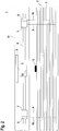
Figur 1 : Ein erstes Ausführungsbeispiel des erfindungsgemäßen Steuerungssystems. -
Figur 2 : Ein zweites Beispiel, welches nicht Teil des erfindungsgemäßen Steuerungssystems ist. -
Figur 1 zeigt ein erstes Ausführungsbeispiel des erfindungsgemäßen Steuerungssystems 1. Das Steuerungssystem 1 dient zur Betätigung einer Jalousie, mittels derer eine Gebäudeöffnung wie ein Fenster oder eine Tür abgedeckt und gegen Sonneneinstrahlung geschützt werden kann. - Die Jalousie umfasst eine Lamellenanordnung 2 mit einer Anordnung von identisch ausgebildeten, in horizontaler Richtung verlaufenden Lamellen 3. Die Lamellenanordnung 2 kann mittels des Steuerungssystems 1 zwischen einer oberen Endposition, in der die Lamellen 3 komplett eingefahren sind und die Gebäudeöffnung freigeben, und einer unteren Endposition, in der die Lamellenanordnung 2 komplett ausgefahren ist und die Gebäudeöffnung verdeckt, verfahren werden.
- Das Steuerungssystem 1 umfasst einen elektrischen Antrieb 4, das heißt einen Elektromotor, der von einer Steuereinheit 5 gesteuert wird. Die Steuereinheit 5 kann von einem Mikroprozessor oder dergleichen gebildet sein.
- Der elektrische Antrieb 4 ist auf einer Welle 6 gelagert. Eine Drehbewegung des elektrischen Antriebs 4 wird in eine entsprechende Drehbewegung der Welle 6 um deren Längsachse umgesetzt. An den längsseitigen Enden der Welle 6 befindet sich jeweils eine Aufrollvorrichtung 7 und eine Kippvorrichtung 8. Mit jeder Aufrollvorrichtung 7 wird eine Zugschnur 9, die an der untersten Lamelle 3 befestigt ist, auf- oder abgewickelt, je nachdem, in welcher Richtung sich die Welle 6 dreht. Mit jeder Kippvorrichtung 8 ist eine Aufhängeschnur 10 verbunden. Durch Verschieben der Aufhängeschnur 10 mittels der Kippvorrichtung 8 können die Neigungen der Lamellen 3 eingestellt werden.
- Die vorgenannten Komponenten des Steuerungssystems 1 sind in einem kastenförmigen Gehäuse 11 integriert.
- Die untere Endposition der Lamelle 3, in der diese komplett ausgefahren ist, kann über die Steuereinheit 5 mittels einer elektronischen oder mechanischen Zählvorrichtung kontrolliert werden.
- Zur Überwachung der oberen Endposition, in welcher die Lamelle 3 vollständig hochgefahren ist, ist ein Endschalter vorgesehen, der erfindungsgemäß von einem analoge Signale generierenden Hallsensor 12 und einem diesem zugeordneten Magneten 13 gebildet ist.
- Der Hallsensor 12 ist im elektrischen Antrieb 4 integriert. Der Magnet 13 ist relativ zum Hallensor 12 beweglich angeordnet. Im Ausführungsbeispiel gemäß
Figur 1 ist der Magnet 13 auf einem Stößel 14 gelagert. Der Stößel 14 selbst ist im Gehäuse 11 in vertikaler Richtung beweglich gelagert, wobei der Stößel 14 nach unten über das Gehäuse 11 hervorsteht. - Das Beispiel gemäß
Figur 2 , welches nicht Teil des erfindungsgemäßen Steuerungssystems ist, unterscheidet sich von der Ausführungsform gemäßFigur 1 nur dadurch, dass der Magnet 13 auf der Oberseite der obersten Lamelle 3 befestigt ist. Der Stößel 14 im Gehäuse 11 entfällt somit. - Bei beiden Ausführungsformen wird in der Steuereinheit 5 das analoge Signal des Hallsensors 12 dazu verwendet, einerseits ein binäres Schaltsignal des Endschalters und andererseits wenigstens ein zusätzliches Ausgangssignal zu generieren.
- Die Schaltzustände des Schaltsignals geben an, ob sich die Lamellenanordnung 2 in der oberen Endposition befindet oder nicht.
- Bei der Ausführungsform gemäß
Figur 1 ist, solange die obere Endposition der Lamellenanordnung 2 noch nicht erreicht ist, die oberste Lamelle 3 noch in Abstand zum Stößel 14, so dass dieser noch nicht betätigt ist. Der Abstand des Magneten 13 auf dem Stößel 14 zum Hallsensor 12 ist daher noch größer als ein Grenzabstand, der dem Schaltpunkt, das heißt dem Übergang zwischen den Schaltzuständen des Schaltsignals, entspricht. In diesem Fall nimmt das Schaltsignal den Schaltzustand "nicht betätigt" ein. Solange sich das Schaltsignal in diesem Schaltzustand befindet, ist die Stromversorgung des elektrischen Antriebs 4 durch die Steuereinheit 5 nicht unterbrochen und die Lamellenanordnung 2 kann mittels des elektrischen Antriebs 4 verfahren werden. - Bei Einfahren der Lamellenanordnung 2 in die obere Endposition, in welcher diese vollständig hochgefahren ist, drückt die oberste Lamelle 3 gegen den Stößel 14 und bewegt den Magneten 13 zum Hallensor 12 hin, so dass der Grenzabstand unterschritten wird. Das Schaltsignal wechselt demnach in den Schaltzustand "betätigt". Liegt dieser Schaltzustand vor, wird in der Steuereinheit 5 ein Steuersignal generiert, mit dem die Stromversorgung des elektrischen Antriebs 4 unterbrochen wird, so dass eine gefahrbringende Bewegung der Lamellenanordnung 2 über die obere Endposition hinaus unterbunden wird.
- In Abhängigkeit der Signale des Hallsensors 12 werden in der Steuereinheit 5 zusätzlich zum Schaltsignal Ausgangssignale generiert.
- Dabei werden in der Steuereinheit 5 zum einen durch Auswertung der von der Distanz des Magneten 13 abhängigen Signale des Hallsensors 12 und dessen zeitlichen Verlauf positions- und geschwindigkeitsabhängige Ausgangssignale generiert, die zur Vorgabe des Fahrverhaltens der Lamellenanordnung 2 verwendet werden können.
- Die positionsabhängigen Ausgangssignale werden darüber für eine Kalibrierung des Schaltpunkts des Schaltsignals verwendet, um so beispielsweise eine Änderung der Lage der obersten Lamelle 3 in der oberen Endposition der Lamellenanordnung 2, die durch eine verschleißbedingte Längenänderung der Zugschnur 9 bedingt sein kann, zu kompensieren.
- Als weiteres Ausgangssignal wird in der Steuereinheit 5 ein Kontrollsignal generiert, ob der Magnet 13 vorhanden ist. Ist der Magnet 13 infolge einer Beschädigung nicht vorhanden, kann mit dem Endschalter keine Kontrolle der oberen Endposition mehr durchgeführt werden. Um dennoch einen sicheren Betrieb des Verfahrens der Lamellenanordnung 2 zu gewährleisten, wird, wenn in der Steuereinheit 5 das Fehlen des Magneten 13 registriert wird, selbsttätig ein Notfallbetrieb gestartet. In diesem Notfallbetrieb wird die Lamellenanordnung 2 nur noch in eingeschränktem Maß hochgefahren, so dass die obere Endposition nicht mehr erreicht wird. Alternativ oder zusätzlich kann über die Steuereinheit 5 ein optisches oder akustisches Warnsignal generiert werden, um einen Benutzer auf die vorhandene Fehlfunktion hinzuweisen.
- Ein weiteres Ausgangssignal kann als Information die Einbaulage des Magneten 13 enthalten. Je nachdem, ob der Nordpol oder der Südpol des Magneten 13 dem Hallsensor 12 zugewandt ist, ergeben sich unterschiedliche Signalverläufe im Hallsensor 12 und damit unterschiedliche Werte des Ausgangssignals. Abhängig von den Werten dieses Ausgangssignals können in der Steuereinheit 5 unterschiedliche Betriebsarten, insbesondere unterschiedliche Profile für das Verfahren der Lamellenanordnung 2, vorgegeben werden.
-
- (1)
- Steuerungssystem
- (2)
- Lamellenanordnung
- (3)
- Lamelle
- (4)
- elektrischer Antrieb
- (5)
- Steuereinheit
- (6)
- Welle
- (7)
- Aufrollvorrichtung
- (8)
- Kippvorrichtung
- (9)
- Zugschnur
- (10)
- Aufhängeschnur
- (11)
- Gehäuse
- (12)
- Hallsensor
- (13)
- Magnet
- (14)
- Stößel
Claims (10)
- Steuerungssystem (1) für eine Jalousie mit einem von einer Steuereinheit (5) gesteuerten elektrischen Antrieb (4), welche ausgebildet sind eine Lamellenanordnung (2) mit parallel zueinander verlaufenden Lamellen (3) hochzufahren oder herunterzufahren, und mit einem Endschalter zur Erfassung der vollständig hochgefahrenen Positionen der Lamellenanordnung (2), wobei der Endschalter einen Hallsensor (12) und einen Magneten (13) aufweist, welche relativ zueinander beweglich angeordnet sind, und wobei aus von dem Hallsensor (12) generierten analogen Signalen ein binäres Schaltsignal und wenigstens ein weiteres Ausgangssignal abgeleitet wird, wobei die beiden Schaltzustände des Schaltsignals signalisieren, ob sich die Jalousie in der vollständig hochgefahrenen Positionen befindet oder nicht, dadurch gekennzeichnet, dass der Magnet (13) in einem in Abstand zum elektrischen Antrieb (4) gelagerten Stößel (14) integriert ist, wobei bei vollständig hochgefahrener Position der Lamellenanordnung (2) durch die oberste Lamelle (3) der Stößel (14) in Richtung des elektrischen Antriebs (4) ausgelenkt ist.
- Steuerungssystem nach Anspruch 1, dadurch gekennzeichnet, dass der Hallsensor (12) im elektrischen Antrieb (4) integriert ist.
- Steuerungssystem nach einem der Ansprüche 1 oder 2, dadurch gekennzeichnet, dass das Schaltsignal und das oder jedes Ausgangssignal in der Steuereinheit (5) generiert werden.
- Steuerungssystem nach einem der Ansprüche 1 bis 3, dadurch gekennzeichnet, dass in Abhängigkeit des oder eines Ausgangssignals das Fahrverhalten der Lamellenanordnung (2) durch die Steuereinheit (5) vorgegeben wird.
- Steuerungssystem nach einem der Ansprüche 1 bis 4, dadurch gekennzeichnet, dass ein Ausgangssignal angibt, ob der Magnet (13) vorhanden ist oder nicht.
- Steuerungssystem nach einem der Ansprüche 1 bis 5, dadurch gekennzeichnet, dass ein Ausgangssignal die Einbaulage des Magneten (13) angibt.
- Steuerungssystem nach einem der Ansprüche 1 bis 6, dadurch gekennzeichnet, dass ein Ausgangssignal als Positionssignal ausgebildet ist.
- Steuerungssystem nach Anspruch 7, dadurch gekennzeichnet, dass in der Steuereinheit (5) in Abhängigkeit des als Positionssignal ausgebildeten Ausgangssignals eine Kalibrierung des den Übergang zwischen den Schaltzuständen definierenden Schaltpunkts des Schaltsignals vorgenommen wird.
- Steuerungssystem nach einem der Ansprüche 1 bis 8, dadurch gekennzeichnet, dass ein Ausgangssignal als Geschwindigkeitssignal ausgebildet ist.
- Steuerungssystem nach einem der Ansprüche 1 bis 9, dadurch gekennzeichnet, dass mittels der Steuereinheit (5) die Stromversorgung des elektrischen Antriebs (4) dann unterbrochen wird, wenn das Schaltsignal den die vollständig hochgefahrene Position der Lamellenanordnung (2) signalisierenden Schaltzustand einnimmt.
Applications Claiming Priority (1)
| Application Number | Priority Date | Filing Date | Title |
|---|---|---|---|
| DE102016102669.7A DE102016102669B4 (de) | 2016-02-16 | 2016-02-16 | Steuerungssystem |
Publications (2)
| Publication Number | Publication Date |
|---|---|
| EP3208416A1 EP3208416A1 (de) | 2017-08-23 |
| EP3208416B1 true EP3208416B1 (de) | 2021-10-06 |
Family
ID=57609750
Family Applications (1)
| Application Number | Title | Priority Date | Filing Date |
|---|---|---|---|
| EP16206607.0A Active EP3208416B1 (de) | 2016-02-16 | 2016-12-23 | Steuerungssystem |
Country Status (2)
| Country | Link |
|---|---|
| EP (1) | EP3208416B1 (de) |
| DE (1) | DE102016102669B4 (de) |
Families Citing this family (1)
| Publication number | Priority date | Publication date | Assignee | Title |
|---|---|---|---|---|
| DE102017221013A1 (de) * | 2017-11-24 | 2019-05-29 | Robert Bosch Gmbh | Rolllabschlusssteuerungseinrichtung |
Family Cites Families (4)
| Publication number | Priority date | Publication date | Assignee | Title |
|---|---|---|---|---|
| DE3806733A1 (de) * | 1988-03-02 | 1989-09-14 | Elero Antrieb Sonnenschutz | Anordnung zur ueberwachung und steuerung von rollaeden und dergleichen |
| IT1287994B1 (it) * | 1996-11-27 | 1998-09-10 | Finvetro Srl | Dispositivo di controllo e comando della corsa di mezzi di intercettazione dei raggi luminosi in vetrocamere |
| US8193742B2 (en) * | 2008-07-22 | 2012-06-05 | Hunter Douglas Inc. | Programmable motor for window coverings |
| DE202009008418U1 (de) | 2009-06-16 | 2009-09-24 | Somfy Sas | Steuerungssystem für einen Elektromotor einer Betätigungseinrichtung für eine Jalousie o.dgl. |
-
2016
- 2016-02-16 DE DE102016102669.7A patent/DE102016102669B4/de active Active
- 2016-12-23 EP EP16206607.0A patent/EP3208416B1/de active Active
Also Published As
| Publication number | Publication date |
|---|---|
| DE102016102669A1 (de) | 2017-08-17 |
| EP3208416A1 (de) | 2017-08-23 |
| DE102016102669B4 (de) | 2025-12-31 |
Similar Documents
| Publication | Publication Date | Title |
|---|---|---|
| DE3806733C2 (de) | ||
| DE3933266A1 (de) | Verfahren zur steuerung eines elektromotors fuer einen rolladen, insbesondere faltrolladen und steuereinheit hierfuer | |
| EP0751274A1 (de) | Stellantrieb | |
| DE4214998A1 (de) | Torantrieb und Verfahren zum Betreiben eines Torantriebes | |
| EP2880234A1 (de) | Überwachungs- und ansteuervorrichtung für eine toreinheit | |
| EP0678649A1 (de) | Rolltor mit Steuervorrichtung | |
| EP3658734B1 (de) | Torsystem | |
| EP3208416B1 (de) | Steuerungssystem | |
| DE102013224148A1 (de) | Verfahren zur Steuerung eines elektrischen Antriebs einer Tür oder eines Türflügels sowie Türsteuereinrichtung | |
| DE9106410U1 (de) | Antrieb für Türen, Tore oder Klappen | |
| DE102016102703B3 (de) | Torantriebsvorrichtung, überkopftor sowie betriebsverfahren hierfür | |
| EP0808986A2 (de) | Steuerung für Antriebe von Toren | |
| EP2592211B1 (de) | Sonnenschutzanlage mit zwei Antriebmotoren | |
| EP2634358B2 (de) | Intelligente Hinderniserkennung | |
| DE102017203639B4 (de) | Höhenverstellvorrichtung für eine Dunstabzugshaube, Dunstabzugshaube und Verfahren zum Einstellen der Position einer Dunstabzugshaube | |
| WO2015078453A1 (de) | Krafterkennungseinrichtung bei industrietoren | |
| DE4337015B4 (de) | Verfahren zur Steuerung eines motorischen Antriebs einer Tür- oder Fensteranlage | |
| EP0544132B1 (de) | Verfahren und Vorrichtung zur Vermeidung von Ueberhitzung von Elektromotoren | |
| EP0859116B1 (de) | Vorrichtung zum Öffnen und Schliessen eines rollbaren Behanges, wie Rolladen, Markise, Rauchschutzvorhang o. dgl. | |
| EP3353612B1 (de) | Verfahren zur steuerung eines elektrischen antriebs sowie elektrischer antrieb | |
| DE102013004098A1 (de) | Vorrichtung zur Steuerung elektromotorischer Antriebe für auf- und abwickelbare Stoffbehänge, Rollladen, Rolltore od. dgl. | |
| DE102004017110A1 (de) | Fensterheber | |
| EP1149451A1 (de) | Verfahren und steuerung zum steuern einer antriebsvorrichtung für eine abschlusseinrichtung eines gebäudes oder einer einfriedung | |
| EP3604705B1 (de) | Vorrichtung zur begrenzung des stellweges von antrieben | |
| DE102011102232A1 (de) | Lichtgitter |
Legal Events
| Date | Code | Title | Description |
|---|---|---|---|
| PUAI | Public reference made under article 153(3) epc to a published international application that has entered the european phase |
Free format text: ORIGINAL CODE: 0009012 |
|
| STAA | Information on the status of an ep patent application or granted ep patent |
Free format text: STATUS: THE APPLICATION HAS BEEN PUBLISHED |
|
| AK | Designated contracting states |
Kind code of ref document: A1 Designated state(s): AL AT BE BG CH CY CZ DE DK EE ES FI FR GB GR HR HU IE IS IT LI LT LU LV MC MK MT NL NO PL PT RO RS SE SI SK SM TR |
|
| AX | Request for extension of the european patent |
Extension state: BA ME |
|
| STAA | Information on the status of an ep patent application or granted ep patent |
Free format text: STATUS: REQUEST FOR EXAMINATION WAS MADE |
|
| 17P | Request for examination filed |
Effective date: 20170914 |
|
| RBV | Designated contracting states (corrected) |
Designated state(s): AL AT BE BG CH CY CZ DE DK EE ES FI FR GB GR HR HU IE IS IT LI LT LU LV MC MK MT NL NO PL PT RO RS SE SI SK SM TR |
|
| GRAP | Despatch of communication of intention to grant a patent |
Free format text: ORIGINAL CODE: EPIDOSNIGR1 |
|
| STAA | Information on the status of an ep patent application or granted ep patent |
Free format text: STATUS: GRANT OF PATENT IS INTENDED |
|
| INTG | Intention to grant announced |
Effective date: 20210609 |
|
| RAP3 | Party data changed (applicant data changed or rights of an application transferred) |
Owner name: ELERO GMBH |
|
| GRAS | Grant fee paid |
Free format text: ORIGINAL CODE: EPIDOSNIGR3 |
|
| GRAA | (expected) grant |
Free format text: ORIGINAL CODE: 0009210 |
|
| STAA | Information on the status of an ep patent application or granted ep patent |
Free format text: STATUS: THE PATENT HAS BEEN GRANTED |
|
| AK | Designated contracting states |
Kind code of ref document: B1 Designated state(s): AL AT BE BG CH CY CZ DE DK EE ES FI FR GB GR HR HU IE IS IT LI LT LU LV MC MK MT NL NO PL PT RO RS SE SI SK SM TR |
|
| REG | Reference to a national code |
Ref country code: GB Ref legal event code: FG4D Free format text: NOT ENGLISH |
|
| REG | Reference to a national code |
Ref country code: CH Ref legal event code: EP Ref country code: AT Ref legal event code: REF Ref document number: 1436385 Country of ref document: AT Kind code of ref document: T Effective date: 20211015 |
|
| REG | Reference to a national code |
Ref country code: DE Ref legal event code: R096 Ref document number: 502016013947 Country of ref document: DE |
|
| REG | Reference to a national code |
Ref country code: IE Ref legal event code: FG4D Free format text: LANGUAGE OF EP DOCUMENT: GERMAN |
|
| REG | Reference to a national code |
Ref country code: LT Ref legal event code: MG9D |
|
| REG | Reference to a national code |
Ref country code: NL Ref legal event code: MP Effective date: 20211006 |
|
| PG25 | Lapsed in a contracting state [announced via postgrant information from national office to epo] |
Ref country code: RS Free format text: LAPSE BECAUSE OF FAILURE TO SUBMIT A TRANSLATION OF THE DESCRIPTION OR TO PAY THE FEE WITHIN THE PRESCRIBED TIME-LIMIT Effective date: 20211006 Ref country code: LT Free format text: LAPSE BECAUSE OF FAILURE TO SUBMIT A TRANSLATION OF THE DESCRIPTION OR TO PAY THE FEE WITHIN THE PRESCRIBED TIME-LIMIT Effective date: 20211006 Ref country code: FI Free format text: LAPSE BECAUSE OF FAILURE TO SUBMIT A TRANSLATION OF THE DESCRIPTION OR TO PAY THE FEE WITHIN THE PRESCRIBED TIME-LIMIT Effective date: 20211006 Ref country code: BG Free format text: LAPSE BECAUSE OF FAILURE TO SUBMIT A TRANSLATION OF THE DESCRIPTION OR TO PAY THE FEE WITHIN THE PRESCRIBED TIME-LIMIT Effective date: 20220106 |
|
| PG25 | Lapsed in a contracting state [announced via postgrant information from national office to epo] |
Ref country code: IS Free format text: LAPSE BECAUSE OF FAILURE TO SUBMIT A TRANSLATION OF THE DESCRIPTION OR TO PAY THE FEE WITHIN THE PRESCRIBED TIME-LIMIT Effective date: 20220206 Ref country code: SE Free format text: LAPSE BECAUSE OF FAILURE TO SUBMIT A TRANSLATION OF THE DESCRIPTION OR TO PAY THE FEE WITHIN THE PRESCRIBED TIME-LIMIT Effective date: 20211006 Ref country code: PT Free format text: LAPSE BECAUSE OF FAILURE TO SUBMIT A TRANSLATION OF THE DESCRIPTION OR TO PAY THE FEE WITHIN THE PRESCRIBED TIME-LIMIT Effective date: 20220207 Ref country code: PL Free format text: LAPSE BECAUSE OF FAILURE TO SUBMIT A TRANSLATION OF THE DESCRIPTION OR TO PAY THE FEE WITHIN THE PRESCRIBED TIME-LIMIT Effective date: 20211006 Ref country code: NO Free format text: LAPSE BECAUSE OF FAILURE TO SUBMIT A TRANSLATION OF THE DESCRIPTION OR TO PAY THE FEE WITHIN THE PRESCRIBED TIME-LIMIT Effective date: 20220106 Ref country code: NL Free format text: LAPSE BECAUSE OF FAILURE TO SUBMIT A TRANSLATION OF THE DESCRIPTION OR TO PAY THE FEE WITHIN THE PRESCRIBED TIME-LIMIT Effective date: 20211006 Ref country code: LV Free format text: LAPSE BECAUSE OF FAILURE TO SUBMIT A TRANSLATION OF THE DESCRIPTION OR TO PAY THE FEE WITHIN THE PRESCRIBED TIME-LIMIT Effective date: 20211006 Ref country code: HR Free format text: LAPSE BECAUSE OF FAILURE TO SUBMIT A TRANSLATION OF THE DESCRIPTION OR TO PAY THE FEE WITHIN THE PRESCRIBED TIME-LIMIT Effective date: 20211006 Ref country code: GR Free format text: LAPSE BECAUSE OF FAILURE TO SUBMIT A TRANSLATION OF THE DESCRIPTION OR TO PAY THE FEE WITHIN THE PRESCRIBED TIME-LIMIT Effective date: 20220107 Ref country code: ES Free format text: LAPSE BECAUSE OF FAILURE TO SUBMIT A TRANSLATION OF THE DESCRIPTION OR TO PAY THE FEE WITHIN THE PRESCRIBED TIME-LIMIT Effective date: 20211006 |
|
| REG | Reference to a national code |
Ref country code: DE Ref legal event code: R097 Ref document number: 502016013947 Country of ref document: DE |
|
| PG25 | Lapsed in a contracting state [announced via postgrant information from national office to epo] |
Ref country code: SM Free format text: LAPSE BECAUSE OF FAILURE TO SUBMIT A TRANSLATION OF THE DESCRIPTION OR TO PAY THE FEE WITHIN THE PRESCRIBED TIME-LIMIT Effective date: 20211006 Ref country code: SK Free format text: LAPSE BECAUSE OF FAILURE TO SUBMIT A TRANSLATION OF THE DESCRIPTION OR TO PAY THE FEE WITHIN THE PRESCRIBED TIME-LIMIT Effective date: 20211006 Ref country code: RO Free format text: LAPSE BECAUSE OF FAILURE TO SUBMIT A TRANSLATION OF THE DESCRIPTION OR TO PAY THE FEE WITHIN THE PRESCRIBED TIME-LIMIT Effective date: 20211006 Ref country code: MC Free format text: LAPSE BECAUSE OF FAILURE TO SUBMIT A TRANSLATION OF THE DESCRIPTION OR TO PAY THE FEE WITHIN THE PRESCRIBED TIME-LIMIT Effective date: 20211006 Ref country code: EE Free format text: LAPSE BECAUSE OF FAILURE TO SUBMIT A TRANSLATION OF THE DESCRIPTION OR TO PAY THE FEE WITHIN THE PRESCRIBED TIME-LIMIT Effective date: 20211006 Ref country code: DK Free format text: LAPSE BECAUSE OF FAILURE TO SUBMIT A TRANSLATION OF THE DESCRIPTION OR TO PAY THE FEE WITHIN THE PRESCRIBED TIME-LIMIT Effective date: 20211006 Ref country code: CZ Free format text: LAPSE BECAUSE OF FAILURE TO SUBMIT A TRANSLATION OF THE DESCRIPTION OR TO PAY THE FEE WITHIN THE PRESCRIBED TIME-LIMIT Effective date: 20211006 |
|
| PLBE | No opposition filed within time limit |
Free format text: ORIGINAL CODE: 0009261 |
|
| STAA | Information on the status of an ep patent application or granted ep patent |
Free format text: STATUS: NO OPPOSITION FILED WITHIN TIME LIMIT |
|
| 26N | No opposition filed |
Effective date: 20220707 |
|
| REG | Reference to a national code |
Ref country code: BE Ref legal event code: MM Effective date: 20211231 |
|
| GBPC | Gb: european patent ceased through non-payment of renewal fee |
Effective date: 20220106 |
|
| PG25 | Lapsed in a contracting state [announced via postgrant information from national office to epo] |
Ref country code: LU Free format text: LAPSE BECAUSE OF NON-PAYMENT OF DUE FEES Effective date: 20211223 Ref country code: IE Free format text: LAPSE BECAUSE OF NON-PAYMENT OF DUE FEES Effective date: 20211223 Ref country code: GB Free format text: LAPSE BECAUSE OF NON-PAYMENT OF DUE FEES Effective date: 20220106 Ref country code: AL Free format text: LAPSE BECAUSE OF FAILURE TO SUBMIT A TRANSLATION OF THE DESCRIPTION OR TO PAY THE FEE WITHIN THE PRESCRIBED TIME-LIMIT Effective date: 20211006 |
|
| PG25 | Lapsed in a contracting state [announced via postgrant information from national office to epo] |
Ref country code: SI Free format text: LAPSE BECAUSE OF FAILURE TO SUBMIT A TRANSLATION OF THE DESCRIPTION OR TO PAY THE FEE WITHIN THE PRESCRIBED TIME-LIMIT Effective date: 20211006 Ref country code: BE Free format text: LAPSE BECAUSE OF NON-PAYMENT OF DUE FEES Effective date: 20211231 |
|
| PG25 | Lapsed in a contracting state [announced via postgrant information from national office to epo] |
Ref country code: IT Free format text: LAPSE BECAUSE OF FAILURE TO SUBMIT A TRANSLATION OF THE DESCRIPTION OR TO PAY THE FEE WITHIN THE PRESCRIBED TIME-LIMIT Effective date: 20211006 Ref country code: HU Free format text: LAPSE BECAUSE OF FAILURE TO SUBMIT A TRANSLATION OF THE DESCRIPTION OR TO PAY THE FEE WITHIN THE PRESCRIBED TIME-LIMIT; INVALID AB INITIO Effective date: 20161223 |
|
| PG25 | Lapsed in a contracting state [announced via postgrant information from national office to epo] |
Ref country code: CY Free format text: LAPSE BECAUSE OF FAILURE TO SUBMIT A TRANSLATION OF THE DESCRIPTION OR TO PAY THE FEE WITHIN THE PRESCRIBED TIME-LIMIT Effective date: 20211006 |
|
| PG25 | Lapsed in a contracting state [announced via postgrant information from national office to epo] |
Ref country code: MK Free format text: LAPSE BECAUSE OF FAILURE TO SUBMIT A TRANSLATION OF THE DESCRIPTION OR TO PAY THE FEE WITHIN THE PRESCRIBED TIME-LIMIT Effective date: 20211006 |
|
| PG25 | Lapsed in a contracting state [announced via postgrant information from national office to epo] |
Ref country code: MT Free format text: LAPSE BECAUSE OF FAILURE TO SUBMIT A TRANSLATION OF THE DESCRIPTION OR TO PAY THE FEE WITHIN THE PRESCRIBED TIME-LIMIT Effective date: 20211006 |
|
| P01 | Opt-out of the competence of the unified patent court (upc) registered |
Free format text: CASE NUMBER: UPC_APP_0010824_3208416/2025 Effective date: 20251023 |
|
| PG25 | Lapsed in a contracting state [announced via postgrant information from national office to epo] |
Ref country code: TR Free format text: LAPSE BECAUSE OF FAILURE TO SUBMIT A TRANSLATION OF THE DESCRIPTION OR TO PAY THE FEE WITHIN THE PRESCRIBED TIME-LIMIT Effective date: 20211006 |
|
| REG | Reference to a national code |
Ref country code: CH Ref legal event code: U11 Free format text: ST27 STATUS EVENT CODE: U-0-0-U10-U11 (AS PROVIDED BY THE NATIONAL OFFICE) Effective date: 20260101 |
|
| PGFP | Annual fee paid to national office [announced via postgrant information from national office to epo] |
Ref country code: DE Payment date: 20250919 Year of fee payment: 10 |
|
| PGFP | Annual fee paid to national office [announced via postgrant information from national office to epo] |
Ref country code: AT Payment date: 20251222 Year of fee payment: 10 |
|
| PGFP | Annual fee paid to national office [announced via postgrant information from national office to epo] |
Ref country code: FR Payment date: 20251223 Year of fee payment: 10 |
|
| REG | Reference to a national code |
Ref country code: CH Ref legal event code: R17 Free format text: ST27 STATUS EVENT CODE: U-0-0-R10-R17 (AS PROVIDED BY THE NATIONAL OFFICE) Effective date: 20260410 |
|
| PGFP | Annual fee paid to national office [announced via postgrant information from national office to epo] |
Ref country code: CH Payment date: 20260101 Year of fee payment: 10 |