EP3208430A1 - Système de nettoyage auxiliaire pour moteurs à turbine à gaz - Google Patents
Système de nettoyage auxiliaire pour moteurs à turbine à gaz Download PDFInfo
- Publication number
- EP3208430A1 EP3208430A1 EP17155652.5A EP17155652A EP3208430A1 EP 3208430 A1 EP3208430 A1 EP 3208430A1 EP 17155652 A EP17155652 A EP 17155652A EP 3208430 A1 EP3208430 A1 EP 3208430A1
- Authority
- EP
- European Patent Office
- Prior art keywords
- gas turbine
- turbine engine
- source
- engine
- cleaning
- Prior art date
- Legal status (The legal status is an assumption and is not a legal conclusion. Google has not performed a legal analysis and makes no representation as to the accuracy of the status listed.)
- Withdrawn
Links
Images

Classifications
-
- F—MECHANICAL ENGINEERING; LIGHTING; HEATING; WEAPONS; BLASTING
- F01—MACHINES OR ENGINES IN GENERAL; ENGINE PLANTS IN GENERAL; STEAM ENGINES
- F01D—NON-POSITIVE DISPLACEMENT MACHINES OR ENGINES, e.g. STEAM TURBINES
- F01D25/00—Component parts, details, or accessories, not provided for in, or of interest apart from, other groups
- F01D25/002—Cleaning of turbomachines
-
- B—PERFORMING OPERATIONS; TRANSPORTING
- B08—CLEANING
- B08B—CLEANING IN GENERAL; PREVENTION OF FOULING IN GENERAL
- B08B3/00—Cleaning by methods involving the use or presence of liquid or steam
- B08B3/04—Cleaning involving contact with liquid
-
- B—PERFORMING OPERATIONS; TRANSPORTING
- B08—CLEANING
- B08B—CLEANING IN GENERAL; PREVENTION OF FOULING IN GENERAL
- B08B9/00—Cleaning hollow articles by methods or apparatus specially adapted thereto
-
- F—MECHANICAL ENGINEERING; LIGHTING; HEATING; WEAPONS; BLASTING
- F01—MACHINES OR ENGINES IN GENERAL; ENGINE PLANTS IN GENERAL; STEAM ENGINES
- F01D—NON-POSITIVE DISPLACEMENT MACHINES OR ENGINES, e.g. STEAM TURBINES
- F01D25/00—Component parts, details, or accessories, not provided for in, or of interest apart from, other groups
- F01D25/34—Turning or inching gear
-
- F—MECHANICAL ENGINEERING; LIGHTING; HEATING; WEAPONS; BLASTING
- F02—COMBUSTION ENGINES; HOT-GAS OR COMBUSTION-PRODUCT ENGINE PLANTS
- F02C—GAS-TURBINE PLANTS; AIR INTAKES FOR JET-PROPULSION PLANTS; CONTROLLING FUEL SUPPLY IN AIR-BREATHING JET-PROPULSION PLANTS
- F02C3/00—Gas-turbine plants characterised by the use of combustion products as the working fluid
- F02C3/04—Gas-turbine plants characterised by the use of combustion products as the working fluid having a turbine driving a compressor
-
- F—MECHANICAL ENGINEERING; LIGHTING; HEATING; WEAPONS; BLASTING
- F05—INDEXING SCHEMES RELATING TO ENGINES OR PUMPS IN VARIOUS SUBCLASSES OF CLASSES F01-F04
- F05D—INDEXING SCHEME FOR ASPECTS RELATING TO NON-POSITIVE-DISPLACEMENT MACHINES OR ENGINES, GAS-TURBINES OR JET-PROPULSION PLANTS
- F05D2230/00—Manufacture
- F05D2230/72—Maintenance
-
- F—MECHANICAL ENGINEERING; LIGHTING; HEATING; WEAPONS; BLASTING
- F05—INDEXING SCHEMES RELATING TO ENGINES OR PUMPS IN VARIOUS SUBCLASSES OF CLASSES F01-F04
- F05D—INDEXING SCHEME FOR ASPECTS RELATING TO NON-POSITIVE-DISPLACEMENT MACHINES OR ENGINES, GAS-TURBINES OR JET-PROPULSION PLANTS
- F05D2260/00—Function
- F05D2260/60—Fluid transfer
- F05D2260/607—Preventing clogging or obstruction of flow paths by dirt, dust, or foreign particles
Definitions
- the present invention relates generally to gas turbine engines, and more specifically, to auxiliary cleaning systems for gas turbine engines.
- a gas turbine engine generally includes, in serial flow order, a compressor section, a combustion section, a turbine section and an exhaust section.
- air enters an inlet of the compressor section where one or more axial or centrifugal compressors progressively compress the air until it reaches the combustion section.
- Fuel is mixed with the compressed air and burned within the combustion section to provide combustion gases.
- the combustion gases are routed from the combustion section through a hot gas path defined within the turbine section and then exhausted from the turbine section via the exhaust section.
- the turbine section includes, in serial flow order, a high pressure (HP) turbine and a low pressure (LP) turbine.
- HP turbine and the LP turbine each include various rotatable turbine components such as a rotor shaft, rotor disks mounted or otherwise carried by the rotor shaft, turbine blades mounted to and radially extending from the periphery of the disks, and various stationary turbine components such as stator vanes or nozzles, turbine shrouds, and engine frames.
- the rotatable and stationary turbine components at least partially define the hot gas path through the turbine section.
- the gas turbine buckets or blades generally have an airfoil shape designed to convert the thermal and kinetic energy of the flow path gases into mechanical rotation of the rotor. As the combustion gases flow through the hot gas path, thermal energy is transferred from the combustion gases to the rotatable and stationary turbine components.
- gas turbine engines are commonly employed on an aircraft.
- compressor blades and vanes can suffer from the accumulation of hydrocarbon deposits, dirt, salt, and corrosion residues, affecting their aerodynamic performance. Such deposits can increase exhaust gas temperature and fuel use and decrease the engine's surge margin.
- Typical water wash procedures include cyclic washing of the engine with large amounts of water and sometimes, a small amount of detergent.
- the starter of the gas turbine engine typically motors the engine at approximately 20% rpm during washing.
- Starter duty cycles typically require a certain amount of downtime between each start of the engine, e.g. sixty (60) minutes between every three (3) starts. Due to such limitations of the starter duty cycle, the water wash capabilities of the gas turbine engine are also limited.
- the present disclosure is directed to an auxiliary cleaning system for cleaning a gas turbine engine.
- the auxiliary cleaning system includes an external motoring source mechanically coupled to one or more engine shafts of the gas turbine engine.
- the external motoring source is configured to turn the one or more shafts.
- the auxiliary cleaning system also includes a cleaning apparatus configured to implement a cleaning procedure on the gas turbine engine while the external motoring source is turning the one or more shafts of the gas turbine engine.
- the present disclosure is directed to a method for cleaning a gas turbine engine.
- the method includes mechanically coupling an external motoring source to one or more engine shafts of the gas turbine engine, with the external motoring source being configured to turn the one or more shafts.
- the method includes turning, via the external motoring source, the one or more shafts of the gas turbine engine.
- the method also includes implementing, via a cleaning apparatus, a cleaning procedure on the gas turbine engine while the shafts are turning.
- the present disclosure is directed to a gas turbine engine assembly.
- the gas turbine engine assembly includes a gas turbine engine having one or more engine shafts and an external motoring source mechanically coupled to the one or more engine shafts.
- the external motoring source is configured to turn the one or more shafts.
- the gas turbine engine assembly also includes a cleaning apparatus configured to implement a cleaning procedure on the gas turbine engine while the external motoring source is turning the one or more shafts of the gas turbine engine.
- first, second, and third may be used interchangeably to distinguish one component from another and are not intended to signify location or importance of the individual components.
- upstream and downstream refer to the relative direction with respect to fluid flow in a fluid pathway.
- upstream refers to the direction from which the fluid flows
- downstream refers to the direction to which the fluid flows.
- the present disclosure is directed to an auxiliary cleaning system for cleaning a gas turbine engine.
- the auxiliary cleaning system includes an external motoring source mechanically coupled to one or more engine shafts of the gas turbine engine.
- the external motoring source is configured to turn the one or more shafts as a cleaning apparatus implements a cleaning procedure on the gas turbine engine.
- the present disclosure provides many advantages not present in the prior art. More specifically, conventional on-wing cleaning and/or water wash capabilities are limited by the starter and/or APU operating requirements.
- the external motoring source of the present disclosure greatly enhances the cleaning and/or water wash capabilities of the gas turbine engine as there are unlimited cycle durations and no wait periods between cycles. Further, by using an external motoring source, the speed and duration of the turning engine shaft(s) can be extended to allow for longer water wash operation under an increased range of conditions.
- the present disclosure is capable of extending the time on-wing for engines and will ultimately lead to less performance related engine removals.
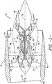
- FIG. 1 illustrates a cross-sectional view of one embodiment of a gas turbine engine 10 that may be utilized within an aircraft in accordance with aspects of the present subject matter, with the engine 10 being shown having a longitudinal or axial centerline axis 12 extending therethrough for reference purposes.
- the engine 10 may include a core gas turbine engine (indicated generally by reference character 14) and a fan section 16 positioned upstream thereof.
- the core engine 14 may generally include a substantially tubular outer casing 18 that defines an annular inlet 20.
- the outer casing 18 may further enclose and support a booster compressor 22 for increasing the pressure of the air that enters the core engine 14 to a first pressure level.
- a high pressure, multi-stage, axial-flow compressor 24 may then receive the pressurized air from the booster compressor 22 and further increase the pressure of such air.
- the pressurized air exiting the high-pressure compressor 24 may then flow to a combustor 26 within which fuel is injected into the flow of pressurized air, with the resulting mixture being combusted within the combustor 26.
- the high energy combustion products are directed from the combustor 26 along the hot gas path of the engine 10 to a first (high pressure) turbine 28 for driving the high pressure compressor 24 via a first (high pressure) drive shaft 30, and then to a second (low pressure) turbine 32 for driving the booster compressor 22 and fan section 16 via a second (low pressure) drive shaft 34 that is generally coaxial with first drive shaft 30.
- the combustion products may be expelled from the core engine 14 via an exhaust nozzle 36 to provide propulsive jet thrust.
- the fan section 16 of the engine 10 may generally include a rotatable, axial-flow fan rotor assembly 38 that is configured to be surrounded by an annular fan casing 40.
- the fan casing 40 may be configured to be supported relative to the core engine 14 by a plurality of substantially radially-extending, circumferentially-spaced outlet guide vanes 42. As such, the fan casing 40 may enclose the fan rotor assembly 38 and its corresponding fan rotor blades 44.
- a downstream section 46 of the fan casing 40 may extend over an outer portion of the core engine 14 so as to define a secondary, or by-pass, airflow conduit 48 that provides additional propulsive jet thrust.
- the gas turbine engine 10 may include a gearbox 25. Further, the gearbox 25 may be configured at any suitable location in the gas turbine engine 10, but is typically mounted on the fan casing 40 or under the high-pressure compressor 24.
- the second (low pressure) drive shaft 34 may be directly coupled to the fan rotor assembly 38 to provide a direct-drive configuration.
- the second drive shaft 34 may be coupled to the fan rotor assembly 38 via a speed reduction device 37 (e.g., a reduction gear or gearbox) to provide an indirect-drive or geared drive configuration.
- a speed reduction device(s) may also be provided between any other suitable shafts and/or spools within the engine 10 as desired or required.
- an initial air flow may enter the engine 10 through an associated inlet 52 of the fan casing 40.
- the air flow 50 then passes through the fan blades 44 and splits into a first compressed air flow (indicated by arrow 54) that moves through conduit 48 and a second compressed air flow (indicated by arrow 56) which enters the booster compressor 22.
- the pressure of the second compressed air flow 56 is then increased and enters the high pressure compressor 24 (as indicated by arrow 58).
- the combustion products 60 exit the combustor 26 and flow through the first turbine 28. Thereafter, the combustion products 60 flow through the second turbine 32 and exit the exhaust nozzle 36 to provide thrust for the engine 10.
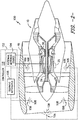
- the gas turbine engine assembly 100 includes a gas turbine engine 10 and an auxiliary cleaning system 102 configured to clean the engine 10 when the engine is not operating.
- the gas turbine engine 10 may include an aircraft engine.
- the aircraft engine may be installed on an aircraft during the cleaning procedure described herein.
- the gas turbine engine 10 has one or more engine shafts 30, 34 and an external motoring source 104 mechanically coupled to the engine shaft(s) 30, 34.
- the external motoring source 104 may include a crank (manual or automatic), a hydraulic motor, an air-driven motor, a water-driven motor, a gas-powered motor, or any other suitable motoring device. Further, the external motoring source 104 may be installed at any suitable location within the gas turbine engine 10, including but example, a starter of the gearbox 25 or a hand cranking port of the gas turbine engine 10. Thus, the external motoring source 104 is configured to turn the engine shaft(s) 30, 34 when the engine 10 is not operating in its normal operating mode (i.e. driven by the engine starter). In addition, for certain embodiments, the external motoring source 104 is not connected to the gas turbine engine 10 when the engine 10 is operating in its normal operating mode. Rather, during the normal operating mode, the starter duty cycle is configured to turn the engine shafts 30, 34.
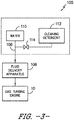
- the auxiliary cleaning system 102 may also include a cleaning apparatus 105 configured to implement a cleaning procedure on the gas turbine engine 10 while the external motoring source 104 is turning the shaft(s) 30, 34 of the gas turbine engine 10. More specifically, as shown in FIG. 3 , the cleaning apparatus 105 may include a fluid delivery apparatus 106 configured to introduce a cleaning liquid 108 containing at least water 110 into the gas turbine engine 10. In certain embodiments, as shown in FIG. 3 , the cleaning liquid 108 may also include any suitable cleaning detergent in any suitable amount. For example, as shown in FIG. 3 , the cleaning detergent 112 may be added to the water 110 via a valve 114 on an as-needed basis. As such, certain wash cycles may include water 110 only, whereas other wash cycles may include water 110 mixed with the cleaning detergent 112.
- the fluid delivery apparatus 106 may include a nozzle 108. Or any other suitable fluid delivery device. It should be understood that any number of nozzles 108 may be included in the cleaning apparatus 105. For example, as shown in FIG. 2 , a total of five nozzles 108 are included in the cleaning apparatus 105. In further embodiments, more than five nozzles 108 or less than five nozzles 108 may be included in the cleaning apparatus 105.
- the method 200 includes mechanically coupling an external motoring source 104 to one or more engine shafts 30, 34 of the gas turbine engine 10, with the external motoring source 104 being configured to turn the shafts 30, 34.
- the method turning, via the external motoring source 104, the shafts 30, 34 of the gas turbine engine 10.
- the method 200 includes implementing, via a cleaning apparatus 105, a cleaning procedure on the gas turbine engine 10 while the shafts 30, 34 are turning.
- the method 200 may also include installing the external motoring source 104 into at least a starter of the gearbox 25 or a hand cranking port of the gas turbine engine 10. In further embodiments, the method 200 may further include disconnecting the external motoring source 104 from the gas turbine engine 10 when the gas turbine engine 10 is operating in a normal operating mode. Thus, in certain embodiments, the external motoring source 104 is configured to operate only when the gas turbine engine 10 is off.
- the method 200 may also include delivering, via a fluid delivery apparatus106 of the cleaning apparatus 105, a cleaning liquid 108 containing at least water 110 into the gas turbine engine 10.
- the method 200 may include controlling a duration of the cleaning procedure. More specifically, since the external motoring source 104 is external to the gas turbine engine 10 and does not depend on the engine starter, the cleaning procedure can be maximized to any suitable length depending on the condition of the turbine engine 10, rather than being limited by the water wash capabilities of the starter duty cycle.
- the auxiliary cleaning system 102 may include a controller 116 configured to control the external motoring source 104 and/or the cleaning apparatus 105.
- the external motoring source 104, as well as the cleaning apparatus 105 may be controlled manually.
Landscapes
- Engineering & Computer Science (AREA)
- Mechanical Engineering (AREA)
- General Engineering & Computer Science (AREA)
- Chemical & Material Sciences (AREA)
- Combustion & Propulsion (AREA)
- Cleaning By Liquid Or Steam (AREA)
- Cleaning In General (AREA)
- Structures Of Non-Positive Displacement Pumps (AREA)
Applications Claiming Priority (1)
| Application Number | Priority Date | Filing Date | Title |
|---|---|---|---|
| US15/047,737 US20170239692A1 (en) | 2016-02-19 | 2016-02-19 | Auxiliary Cleaning System for Gas Turbine Engines |
Publications (1)
| Publication Number | Publication Date |
|---|---|
| EP3208430A1 true EP3208430A1 (fr) | 2017-08-23 |
Family
ID=58016633
Family Applications (1)
| Application Number | Title | Priority Date | Filing Date |
|---|---|---|---|
| EP17155652.5A Withdrawn EP3208430A1 (fr) | 2016-02-19 | 2017-02-10 | Système de nettoyage auxiliaire pour moteurs à turbine à gaz |
Country Status (5)
| Country | Link |
|---|---|
| US (1) | US20170239692A1 (fr) |
| EP (1) | EP3208430A1 (fr) |
| CN (1) | CN107100681A (fr) |
| CA (1) | CA2957487A1 (fr) |
| SG (1) | SG10201700926TA (fr) |
Cited By (2)
| Publication number | Priority date | Publication date | Assignee | Title |
|---|---|---|---|---|
| US10364699B2 (en) | 2013-10-02 | 2019-07-30 | Aerocore Technologies Llc | Cleaning method for jet engine |
| US11643946B2 (en) | 2013-10-02 | 2023-05-09 | Aerocore Technologies Llc | Cleaning method for jet engine |
Families Citing this family (4)
| Publication number | Priority date | Publication date | Assignee | Title |
|---|---|---|---|---|
| CN107514312B (zh) * | 2017-09-04 | 2019-07-02 | 中国航发南方工业有限公司 | 燃机的气动清理电磁阀的控制装置及控制方法 |
| US11530635B2 (en) * | 2018-12-11 | 2022-12-20 | Raytheon Technologies Corporation | Fluid injection systems for gas turbine engines |
| GB201914723D0 (en) | 2019-10-11 | 2019-11-27 | Rolls Royce Plc | Cleaning system and a method of cleaning |
| CN111734689B (zh) * | 2020-07-02 | 2021-09-17 | 中国航发常州兰翔机械有限责任公司 | 一种航空发动机两级热态清洗装置及其工作方法 |
Citations (6)
| Publication number | Priority date | Publication date | Assignee | Title |
|---|---|---|---|---|
| WO2005120953A1 (fr) * | 2004-06-14 | 2005-12-22 | Gas Turbine Efficiency Ab | Systeme servant a laver un moteur de turbine a gaz aerienne |
| US20140000656A1 (en) * | 2012-06-27 | 2014-01-02 | United Technologies Corporation | Engine wash apparatus and method |
| US20140208762A1 (en) * | 2013-01-31 | 2014-07-31 | Solar Turbines Incorporated | Compressor wash with air to bearing buffering system |
| WO2015051146A1 (fr) * | 2013-10-02 | 2015-04-09 | Aerocore Technologies Llc | Procédé de nettoyage pour moteur à réaction |
| EP2876263A1 (fr) * | 2013-11-21 | 2015-05-27 | General Electric Company | Système de lavage à l'eau automatisé pour une turbine à gaz et procédé d'opération |
| EP2982606A1 (fr) * | 2014-08-04 | 2016-02-10 | Rolls-Royce Corporation | Système de nettoyage de moteur d'aéronef |
Family Cites Families (5)
| Publication number | Priority date | Publication date | Assignee | Title |
|---|---|---|---|---|
| US6726779B2 (en) * | 2001-04-09 | 2004-04-27 | Ecolab Inc. | Method for washing a vehicle |
| US9790808B2 (en) * | 2005-04-04 | 2017-10-17 | Ecoservices, Llc | Mobile on-wing engine washing and water reclamation system |
| US7571735B2 (en) * | 2006-09-29 | 2009-08-11 | Gas Turbine Efficiency Sweden Ab | Nozzle for online and offline washing of gas turbine compressors |
| ITFI20110269A1 (it) * | 2011-12-12 | 2013-06-13 | Nuovo Pignone Spa | "turning gear for gas turbine arrangements" |
| US8998567B2 (en) * | 2012-06-08 | 2015-04-07 | General Electric Company | Method, system and apparatus for enhanced off line compressor and turbine cleaning |
-
2016
- 2016-02-19 US US15/047,737 patent/US20170239692A1/en not_active Abandoned
-
2017
- 2017-02-06 SG SG10201700926TA patent/SG10201700926TA/en unknown
- 2017-02-09 CA CA2957487A patent/CA2957487A1/fr not_active Abandoned
- 2017-02-10 EP EP17155652.5A patent/EP3208430A1/fr not_active Withdrawn
- 2017-02-17 CN CN201710085941.3A patent/CN107100681A/zh active Pending
Patent Citations (6)
| Publication number | Priority date | Publication date | Assignee | Title |
|---|---|---|---|---|
| WO2005120953A1 (fr) * | 2004-06-14 | 2005-12-22 | Gas Turbine Efficiency Ab | Systeme servant a laver un moteur de turbine a gaz aerienne |
| US20140000656A1 (en) * | 2012-06-27 | 2014-01-02 | United Technologies Corporation | Engine wash apparatus and method |
| US20140208762A1 (en) * | 2013-01-31 | 2014-07-31 | Solar Turbines Incorporated | Compressor wash with air to bearing buffering system |
| WO2015051146A1 (fr) * | 2013-10-02 | 2015-04-09 | Aerocore Technologies Llc | Procédé de nettoyage pour moteur à réaction |
| EP2876263A1 (fr) * | 2013-11-21 | 2015-05-27 | General Electric Company | Système de lavage à l'eau automatisé pour une turbine à gaz et procédé d'opération |
| EP2982606A1 (fr) * | 2014-08-04 | 2016-02-10 | Rolls-Royce Corporation | Système de nettoyage de moteur d'aéronef |
Cited By (2)
| Publication number | Priority date | Publication date | Assignee | Title |
|---|---|---|---|---|
| US10364699B2 (en) | 2013-10-02 | 2019-07-30 | Aerocore Technologies Llc | Cleaning method for jet engine |
| US11643946B2 (en) | 2013-10-02 | 2023-05-09 | Aerocore Technologies Llc | Cleaning method for jet engine |
Also Published As
| Publication number | Publication date |
|---|---|
| CA2957487A1 (fr) | 2017-08-19 |
| US20170239692A1 (en) | 2017-08-24 |
| SG10201700926TA (en) | 2017-09-28 |
| CN107100681A (zh) | 2017-08-29 |
Similar Documents
| Publication | Publication Date | Title |
|---|---|---|
| CN110234844B (zh) | 燃气涡轮发动机清洗系统 | |
| EP3208430A1 (fr) | Système de nettoyage auxiliaire pour moteurs à turbine à gaz | |
| US10213883B2 (en) | System and method for in situ repair of gas turbine engine casing clearance | |
| US11306658B2 (en) | Cooling system for a turbine engine | |
| EP3192590B1 (fr) | Système et procédé de nettoyage in situ de composants internes d'un turbine à gaz et un ensemble de prises associé | |
| JP2017025908A (ja) | タービンエンジン用冷却システム | |
| JP2017025914A (ja) | タービンエンジン用冷却システム | |
| CN109958484B (zh) | 缓解涡轮发动机中的转子弯曲的结构和方法 | |
| EP3000987A1 (fr) | Moteur à turbine à gaz et procédé de lavage d'un tel moteur | |
| US10436151B2 (en) | Modular fan for a gas turbine engine | |
| EP2900987A1 (fr) | Rapport de puissance de soutirage | |
| EP3208418B1 (fr) | Système de réparation d'une déformation dans une pale de turbine | |
| EP2898206A1 (fr) | Module de système d'engrenage d'entraînement de soufflante et mécanisme d'accouplement d'aube de guidage d'entrée | |
| CN109996934B (zh) | 用于燃气涡轮发动机清洗组件的收集系统 |
Legal Events
| Date | Code | Title | Description |
|---|---|---|---|
| PUAI | Public reference made under article 153(3) epc to a published international application that has entered the european phase |
Free format text: ORIGINAL CODE: 0009012 |
|
| STAA | Information on the status of an ep patent application or granted ep patent |
Free format text: STATUS: THE APPLICATION HAS BEEN PUBLISHED |
|
| AK | Designated contracting states |
Kind code of ref document: A1 Designated state(s): AL AT BE BG CH CY CZ DE DK EE ES FI FR GB GR HR HU IE IS IT LI LT LU LV MC MK MT NL NO PL PT RO RS SE SI SK SM TR |
|
| AX | Request for extension of the european patent |
Extension state: BA ME |
|
| STAA | Information on the status of an ep patent application or granted ep patent |
Free format text: STATUS: REQUEST FOR EXAMINATION WAS MADE |
|
| 17P | Request for examination filed |
Effective date: 20180223 |
|
| RBV | Designated contracting states (corrected) |
Designated state(s): AL AT BE BG CH CY CZ DE DK EE ES FI FR GB GR HR HU IE IS IT LI LT LU LV MC MK MT NL NO PL PT RO RS SE SI SK SM TR |
|
| STAA | Information on the status of an ep patent application or granted ep patent |
Free format text: STATUS: EXAMINATION IS IN PROGRESS |
|
| 17Q | First examination report despatched |
Effective date: 20191015 |
|
| STAA | Information on the status of an ep patent application or granted ep patent |
Free format text: STATUS: THE APPLICATION IS DEEMED TO BE WITHDRAWN |
|
| 18D | Application deemed to be withdrawn |
Effective date: 20201215 |