EP3208509B1 - Sicherheitskamera mit mobiler unterstützung - Google Patents
Sicherheitskamera mit mobiler unterstützung Download PDFInfo
- Publication number
- EP3208509B1 EP3208509B1 EP16382066.5A EP16382066A EP3208509B1 EP 3208509 B1 EP3208509 B1 EP 3208509B1 EP 16382066 A EP16382066 A EP 16382066A EP 3208509 B1 EP3208509 B1 EP 3208509B1
- Authority
- EP
- European Patent Office
- Prior art keywords
- camera
- sphere
- support
- spherical concavity
- focusing
- Prior art date
- Legal status (The legal status is an assumption and is not a legal conclusion. Google has not performed a legal analysis and makes no representation as to the accuracy of the status listed.)
- Not-in-force
Links
Images
Classifications
-
- F—MECHANICAL ENGINEERING; LIGHTING; HEATING; WEAPONS; BLASTING
- F16—ENGINEERING ELEMENTS AND UNITS; GENERAL MEASURES FOR PRODUCING AND MAINTAINING EFFECTIVE FUNCTIONING OF MACHINES OR INSTALLATIONS; THERMAL INSULATION IN GENERAL
- F16M—FRAMES, CASINGS OR BEDS OF ENGINES, MACHINES OR APPARATUS, NOT SPECIFIC TO ENGINES, MACHINES OR APPARATUS PROVIDED FOR ELSEWHERE; STANDS; SUPPORTS
- F16M11/00—Stands or trestles as supports for apparatus or articles placed thereon ; Stands for scientific apparatus such as gravitational force meters
- F16M11/02—Heads
- F16M11/04—Means for attachment of apparatus; Means allowing adjustment of the apparatus relatively to the stand
- F16M11/06—Means for attachment of apparatus; Means allowing adjustment of the apparatus relatively to the stand allowing pivoting
- F16M11/12—Means for attachment of apparatus; Means allowing adjustment of the apparatus relatively to the stand allowing pivoting in more than one direction
- F16M11/14—Means for attachment of apparatus; Means allowing adjustment of the apparatus relatively to the stand allowing pivoting in more than one direction with ball-joint
-
- F—MECHANICAL ENGINEERING; LIGHTING; HEATING; WEAPONS; BLASTING
- F16—ENGINEERING ELEMENTS AND UNITS; GENERAL MEASURES FOR PRODUCING AND MAINTAINING EFFECTIVE FUNCTIONING OF MACHINES OR INSTALLATIONS; THERMAL INSULATION IN GENERAL
- F16M—FRAMES, CASINGS OR BEDS OF ENGINES, MACHINES OR APPARATUS, NOT SPECIFIC TO ENGINES, MACHINES OR APPARATUS PROVIDED FOR ELSEWHERE; STANDS; SUPPORTS
- F16M11/00—Stands or trestles as supports for apparatus or articles placed thereon ; Stands for scientific apparatus such as gravitational force meters
- F16M11/02—Heads
- F16M11/04—Means for attachment of apparatus; Means allowing adjustment of the apparatus relatively to the stand
- F16M11/041—Allowing quick release of the apparatus
Definitions
- the object of the present invention is a security camera with mobile support comprising a magnetic ball joint attachment allowing the placement of the camera in any position and a rotation angle of 360o.
- security cameras usually have complex fixed or remotely operated mechanical supports that complicate the installation and, in addition, do not allow a versatile image focusing.
- the document US2012/0114324 discloses an enhanced magnetic directional mount for mounting, positioning, and orienting an electronic device such as a camera.
- the base mounting surface is configured to maximize the extent of adjustment and ease of adjustability of the electronic device, and the base mounting surface and housing mounting surface are designed to provide smooth and secure movement in the electronic device position.
- the document US2013/0078855 discloses a mount for supportably engaging an article.
- the mount includes a bulbous member that may include a convexly shaped surface area.
- the convexly shaped surface area may be supportively contactable with a first interconnect portion of a carrier member.
- An attachment member that is operatively associable with a device may be removably engageable with a second interconnect portion of the carrier member.
- the carrier member may be moved throughout a continuum of positions defined by the convexly curved surface area of the bulbous member.
- the bulbous member may be supportably engaged by a variety of embodiments of support structures for supporting or mounting the mount.
- the advantages of a light security camera with a very versatile support structure allowing a positioning at 360o are combined.
- the freedom of movement of the ball joint reside, firstly, on freedom of movement of the sphere that makes up the ball joint and that is far superior to other ball joints described in the State of the art which need additional connections of the thread type, or the like. Therefore, there are no obstacles for its turn in any direction given that the accommodation in the body of the camera is very shallow in relation to other ball joint systems. Since the magnetic coupling is shallow, the friction is minimal and the smoothness of movements is greater.
- the magnetic coupling allows closing an internal circuit that enables the camera power on and off and, where appropriate, the notifying a central surveillance system such as that described in WO2015044487 when the camera is disabled.
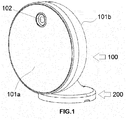
- the present invention comprises two elements or bodies (100, 200) separable from each other.
- the first body 100 is configured to house a surveillance or security camera and the second body 200 is configured as a support or anchor attached to an anchorage point, e.g., an architectural enclosure.
- the first body 100 is essentially circular and flat and is configured to house therein a surveillance camera and electronics associated with the same.
- the first body 100 comprises two facing surfaces, a first front surface 101a and a second back surface 101b.
- the opening to enable the operation of the camera lens 102 is located in the first front surface 101a.
- such port is a mini USB port, although logically any person skilled in the art does not rule out other means or power supply ports with identical functionality.
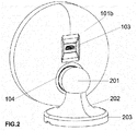
- the second back surface 101b of the body 100 has a spherical concavity 104 the central part of which makes up the housing for a sphere 201 of the second support body 200 and which is rotary with regard to the spherical concavity 104 of the first body 100.
- the sphere 201 and concavity 104 are magnetically joined in use position, as shown the FIGs. 1-2 .
- This magnetic coupling between sphere 201 and concavity 104 also has the particularity of closing a circuit in such a way that the camera is active only when el first body 100 is joined to the second body 200, being able to power on and off with the simple act of anchoring or unanchoring both bodies from each other.
- This type of attachment and its power on/off operation has the advantage that when it is used in security systems, for example that described in WO2015044487 in the event that someone maliciously forces the withdrawal of the first body 100 containing the camera, it automatically generates a notification to the security centre described in such document.
- the magnetic ball joint attachment implemented by the present invention and shown in FIGs. 1-2 in a particular embodiment thereof further comprises an internal accelerometer, housed in the first body 100 and which self-orientates the images captured through the lens 102. Indeed, with the use, the first body 100, and also the lens 102, may have altered its position so in this additional embodiment the means for transmitting the image can also send the position of the first body 100 as metadata to correct the focusing of the lens 102 until a correct focusing.
- the first body 100 comprises at least two laser pointers marking or pointing the ends of the correct field of view, that is, the field of view where the focusing of the lens 102 allows taking a straight image of the element under surveillance.
- the second body or support 200 is completed with a pin 202 connected in turn with a base 203 that is capable of being firmly attached with an architectural structure, for example, a wall.
Landscapes
- Engineering & Computer Science (AREA)
- General Engineering & Computer Science (AREA)
- Mechanical Engineering (AREA)
- Studio Devices (AREA)
- Accessories Of Cameras (AREA)
- Closed-Circuit Television Systems (AREA)
Claims (4)
- Sicherheitskamera mit mobiler Unterstützung, bestehend aus:einen ersten Körper (100) und einen zweiten Körper (200), die voneinander trennbar sind, wobei der erste Körper (100) so konfiguriert ist, dass er eine Überwachungs- oder Sicherheitskamera aufnimmt, und der zweite Körper (200) als ein Träger des ersten Körpers (100) konfiguriert ist, der fest an einem Verankerungspunkt angebracht ist;wobei der erste Körper (100) zwei einander zugewandte Oberflächen aufweist, eine erste vordere Oberfläche (101a) und eine zweite hintere Oberfläche (101b); und wobei die erste vordere Oberfläche (101a) mindestens eine Öffnung für den Durchgang von mindestens einer Kameralinse (102) aufweist; und wobei die zweite hintere Oberfläche (101b) des ersten Körpers (100) eine kugelförmige Aushöhlung (104) aufweist;wobei die Sicherheitskamera eine Kugelgelenkbaugruppe umfasst, die aus einer Kugel (201) des zweiten Trägerkörpers (200) besteht, die in dem zentralen Teil der kugelförmigen Aushöhlung (104) untergebracht ist; wobei die Kugel (201) in Bezug auf die kugelförmige Aushöhlung (104) des ersten Körpers (100) um 360° drehbar ist;dadurch gekennzeichnet, dass die Kugel (201) und die kugelförmige Aushöhlung (104) magnetisch verbunden sind und einen elektronischen Schaltkreis derart schließen, dass die Kamera nur dann aktiv ist, wenn die Kugel (201) des zweiten Trägerkörpers (200) in dem zentralen Teil der kugelförmigen Aushöhlung (104) des ersten Körpers (100) untergebracht ist; undwobei der erste Körper (100) einen Beschleunigungsmesser beherbergt, der so konfiguriert ist, dass er das durch das Kameraobjektiv (102) aufgenommene Bild so ausrichtet, dass Mittel, die zur Übertragung des Bildes vom Kameraobjektiv angeordnet sind, auch die Position des ersten Körpers (100) als Metadaten senden, um die Fokussierung des Kameraobjektivs (102) bis zu einer korrekten Fokussierung zu korrigieren.
- Kamera nach Anspruch 1 mit mindestens zwei Laserpointern, die auf die Enden des Sichtfeldes zeigen, wo die Fokussierung des Objektivs (102) die Aufnahme eines geraden Bildes eines zu überwachenden Elements ermöglicht.
- Kamera nach einem der Ansprüche 1 bis 2, wobei der zweite Körper (200) durch einen Stift (202) vervollständigt wird, der seinerseits mit einem Sockel (203) verbunden ist, der fest an einer architektonischen Struktur angebracht werden kann.
- Kamera nach Anspruch 1, bei der die zweite Rückfläche (101b) des ersten Gehäuses (100) einen Anschluss (103) aufweist, der für die Stromversorgung mindestens einer im ersten Gehäuse (100) integrierten Batterie geeignet ist.
Priority Applications (3)
| Application Number | Priority Date | Filing Date | Title |
|---|---|---|---|
| ES16382066T ES2912184T3 (es) | 2016-02-19 | 2016-02-19 | Cámara de seguridad con soporte móvil |
| EP16382066.5A EP3208509B1 (de) | 2016-02-19 | 2016-02-19 | Sicherheitskamera mit mobiler unterstützung |
| PCT/EP2017/053821 WO2017140915A1 (en) | 2016-02-19 | 2017-02-20 | Security camera with mobile support |
Applications Claiming Priority (1)
| Application Number | Priority Date | Filing Date | Title |
|---|---|---|---|
| EP16382066.5A EP3208509B1 (de) | 2016-02-19 | 2016-02-19 | Sicherheitskamera mit mobiler unterstützung |
Publications (2)
| Publication Number | Publication Date |
|---|---|
| EP3208509A1 EP3208509A1 (de) | 2017-08-23 |
| EP3208509B1 true EP3208509B1 (de) | 2022-01-12 |
Family
ID=55589789
Family Applications (1)
| Application Number | Title | Priority Date | Filing Date |
|---|---|---|---|
| EP16382066.5A Not-in-force EP3208509B1 (de) | 2016-02-19 | 2016-02-19 | Sicherheitskamera mit mobiler unterstützung |
Country Status (3)
| Country | Link |
|---|---|
| EP (1) | EP3208509B1 (de) |
| ES (1) | ES2912184T3 (de) |
| WO (1) | WO2017140915A1 (de) |
Families Citing this family (1)
| Publication number | Priority date | Publication date | Assignee | Title |
|---|---|---|---|---|
| US10267454B1 (en) | 2018-01-08 | 2019-04-23 | TP-Link Research America Corp | Security monitoring system |
Family Cites Families (7)
| Publication number | Priority date | Publication date | Assignee | Title |
|---|---|---|---|---|
| US20080023607A1 (en) | 2004-03-17 | 2008-01-31 | Trek Technologies, Llc, Dba Trek Tech | Magnetic-based releasable, adjustable camera or other device mount apparatus |
| US8414201B2 (en) * | 2008-01-31 | 2013-04-09 | Avaak, Inc. | Spherical mounting and positioning system |
| US20090196597A1 (en) * | 2008-01-31 | 2009-08-06 | Gioia Messinger | Mounting and Positioning System |
| US9097379B1 (en) | 2010-10-25 | 2015-08-04 | Gomite, LLC | Articulating support for electronic devices |
| EP2748690A4 (de) * | 2011-08-25 | 2015-08-05 | Iomounts Llc | Vorrichtung und verfahren zur stütze eines gegenstandes |
| ES2534702B1 (es) | 2013-09-24 | 2016-02-09 | Ontech Security, Sl | Sensor de campos electrostáticos y sistema de seguridad en espacios interiores |
| US10206522B2 (en) * | 2014-01-24 | 2019-02-19 | Apple Inc. | Display systems and methods |
-
2016
- 2016-02-19 ES ES16382066T patent/ES2912184T3/es active Active
- 2016-02-19 EP EP16382066.5A patent/EP3208509B1/de not_active Not-in-force
-
2017
- 2017-02-20 WO PCT/EP2017/053821 patent/WO2017140915A1/en not_active Ceased
Also Published As
| Publication number | Publication date |
|---|---|
| WO2017140915A1 (en) | 2017-08-24 |
| ES2912184T3 (es) | 2022-05-24 |
| EP3208509A1 (de) | 2017-08-23 |
Similar Documents
| Publication | Publication Date | Title |
|---|---|---|
| US8414201B2 (en) | Spherical mounting and positioning system | |
| US12366321B2 (en) | Magnet-based quick release assembly and gimbal system | |
| US20190215423A1 (en) | Security monitoring system | |
| US20130068915A1 (en) | Detachable mounting systems for electronic devices | |
| US20090196597A1 (en) | Mounting and Positioning System | |
| EP3220036B1 (de) | Kugelgelenk | |
| US10713811B2 (en) | Security camera system with multi-directional mount and method of operation | |
| EP3562140B1 (de) | Zweiachsiges schwenkkamerasystem mit konfiguration zur aufrechterhaltung eines ebenen bildes bei montage an einer wand oder einer decke | |
| US9176364B2 (en) | Deployable storable mirror | |
| EP2876349A1 (de) | Montagewinkel | |
| EP3264740B1 (de) | Modulare kamerablöcke zur erfassung von virtueller realität | |
| US20160138754A1 (en) | Magnetic universal mounting assembly | |
| EP3041214B1 (de) | Bildgebungsvorrichtung | |
| CN104125376A (zh) | 具有集成安装特点的监视摄像机 | |
| US20180017752A1 (en) | Camera device and terminal having same | |
| US20160116183A1 (en) | Magnetically mounted wall thermostat | |
| JP3196633U (ja) | 監視装置 | |
| US11903467B1 (en) | Mobile device case and mount with magnetic lock | |
| DE102016006308A1 (de) | Kamera beliebiger Art | |
| EP4045959B1 (de) | Aktuatoren für erweiterten drehbereich mit zwei freiheitsgraden | |
| WO2017140915A1 (en) | Security camera with mobile support | |
| EP4356195B1 (de) | Kameraschutzabdeckung | |
| CN213693888U (zh) | 摄像头装置 | |
| US20200279682A1 (en) | Magnetic levitation mounted and controlled payload on a curved surface | |
| US8777166B2 (en) | Modular optical box |
Legal Events
| Date | Code | Title | Description |
|---|---|---|---|
| PUAI | Public reference made under article 153(3) epc to a published international application that has entered the european phase |
Free format text: ORIGINAL CODE: 0009012 |
|
| STAA | Information on the status of an ep patent application or granted ep patent |
Free format text: STATUS: THE APPLICATION HAS BEEN PUBLISHED |
|
| AK | Designated contracting states |
Kind code of ref document: A1 Designated state(s): AL AT BE BG CH CY CZ DE DK EE ES FI FR GB GR HR HU IE IS IT LI LT LU LV MC MK MT NL NO PL PT RO RS SE SI SK SM TR |
|
| AX | Request for extension of the european patent |
Extension state: BA ME |
|
| STAA | Information on the status of an ep patent application or granted ep patent |
Free format text: STATUS: REQUEST FOR EXAMINATION WAS MADE |
|
| 17P | Request for examination filed |
Effective date: 20180222 |
|
| RBV | Designated contracting states (corrected) |
Designated state(s): AL AT BE BG CH CY CZ DE DK EE ES FI FR GB GR HR HU IE IS IT LI LT LU LV MC MK MT NL NO PL PT RO RS SE SI SK SM TR |
|
| STAA | Information on the status of an ep patent application or granted ep patent |
Free format text: STATUS: EXAMINATION IS IN PROGRESS |
|
| 17Q | First examination report despatched |
Effective date: 20190528 |
|
| RIC1 | Information provided on ipc code assigned before grant |
Ipc: F16M 11/14 20060101AFI20210611BHEP Ipc: F16M 11/04 20060101ALI20210611BHEP |
|
| GRAP | Despatch of communication of intention to grant a patent |
Free format text: ORIGINAL CODE: EPIDOSNIGR1 |
|
| STAA | Information on the status of an ep patent application or granted ep patent |
Free format text: STATUS: GRANT OF PATENT IS INTENDED |
|
| INTG | Intention to grant announced |
Effective date: 20210730 |
|
| GRAS | Grant fee paid |
Free format text: ORIGINAL CODE: EPIDOSNIGR3 |
|
| GRAA | (expected) grant |
Free format text: ORIGINAL CODE: 0009210 |
|
| STAA | Information on the status of an ep patent application or granted ep patent |
Free format text: STATUS: THE PATENT HAS BEEN GRANTED |
|
| AK | Designated contracting states |
Kind code of ref document: B1 Designated state(s): AL AT BE BG CH CY CZ DE DK EE ES FI FR GB GR HR HU IE IS IT LI LT LU LV MC MK MT NL NO PL PT RO RS SE SI SK SM TR |
|
| REG | Reference to a national code |
Ref country code: GB Ref legal event code: FG4D |
|
| REG | Reference to a national code |
Ref country code: CH Ref legal event code: EP |
|
| REG | Reference to a national code |
Ref country code: DE Ref legal event code: R096 Ref document number: 602016068271 Country of ref document: DE |
|
| REG | Reference to a national code |
Ref country code: IE Ref legal event code: FG4D |
|
| REG | Reference to a national code |
Ref country code: AT Ref legal event code: REF Ref document number: 1462613 Country of ref document: AT Kind code of ref document: T Effective date: 20220215 |
|
| REG | Reference to a national code |
Ref country code: LT Ref legal event code: MG9D |
|
| REG | Reference to a national code |
Ref country code: NL Ref legal event code: MP Effective date: 20220112 |
|
| REG | Reference to a national code |
Ref country code: ES Ref legal event code: FG2A Ref document number: 2912184 Country of ref document: ES Kind code of ref document: T3 Effective date: 20220524 |
|
| REG | Reference to a national code |
Ref country code: AT Ref legal event code: MK05 Ref document number: 1462613 Country of ref document: AT Kind code of ref document: T Effective date: 20220112 |
|
| PG25 | Lapsed in a contracting state [announced via postgrant information from national office to epo] |
Ref country code: NL Free format text: LAPSE BECAUSE OF FAILURE TO SUBMIT A TRANSLATION OF THE DESCRIPTION OR TO PAY THE FEE WITHIN THE PRESCRIBED TIME-LIMIT Effective date: 20220112 |
|
| PG25 | Lapsed in a contracting state [announced via postgrant information from national office to epo] |
Ref country code: SE Free format text: LAPSE BECAUSE OF FAILURE TO SUBMIT A TRANSLATION OF THE DESCRIPTION OR TO PAY THE FEE WITHIN THE PRESCRIBED TIME-LIMIT Effective date: 20220112 Ref country code: RS Free format text: LAPSE BECAUSE OF FAILURE TO SUBMIT A TRANSLATION OF THE DESCRIPTION OR TO PAY THE FEE WITHIN THE PRESCRIBED TIME-LIMIT Effective date: 20220112 Ref country code: PT Free format text: LAPSE BECAUSE OF FAILURE TO SUBMIT A TRANSLATION OF THE DESCRIPTION OR TO PAY THE FEE WITHIN THE PRESCRIBED TIME-LIMIT Effective date: 20220512 Ref country code: NO Free format text: LAPSE BECAUSE OF FAILURE TO SUBMIT A TRANSLATION OF THE DESCRIPTION OR TO PAY THE FEE WITHIN THE PRESCRIBED TIME-LIMIT Effective date: 20220412 Ref country code: LT Free format text: LAPSE BECAUSE OF FAILURE TO SUBMIT A TRANSLATION OF THE DESCRIPTION OR TO PAY THE FEE WITHIN THE PRESCRIBED TIME-LIMIT Effective date: 20220112 Ref country code: HR Free format text: LAPSE BECAUSE OF FAILURE TO SUBMIT A TRANSLATION OF THE DESCRIPTION OR TO PAY THE FEE WITHIN THE PRESCRIBED TIME-LIMIT Effective date: 20220112 Ref country code: BG Free format text: LAPSE BECAUSE OF FAILURE TO SUBMIT A TRANSLATION OF THE DESCRIPTION OR TO PAY THE FEE WITHIN THE PRESCRIBED TIME-LIMIT Effective date: 20220412 |
|
| PG25 | Lapsed in a contracting state [announced via postgrant information from national office to epo] |
Ref country code: PL Free format text: LAPSE BECAUSE OF FAILURE TO SUBMIT A TRANSLATION OF THE DESCRIPTION OR TO PAY THE FEE WITHIN THE PRESCRIBED TIME-LIMIT Effective date: 20220112 Ref country code: LV Free format text: LAPSE BECAUSE OF FAILURE TO SUBMIT A TRANSLATION OF THE DESCRIPTION OR TO PAY THE FEE WITHIN THE PRESCRIBED TIME-LIMIT Effective date: 20220112 Ref country code: GR Free format text: LAPSE BECAUSE OF FAILURE TO SUBMIT A TRANSLATION OF THE DESCRIPTION OR TO PAY THE FEE WITHIN THE PRESCRIBED TIME-LIMIT Effective date: 20220413 Ref country code: FI Free format text: LAPSE BECAUSE OF FAILURE TO SUBMIT A TRANSLATION OF THE DESCRIPTION OR TO PAY THE FEE WITHIN THE PRESCRIBED TIME-LIMIT Effective date: 20220112 Ref country code: AT Free format text: LAPSE BECAUSE OF FAILURE TO SUBMIT A TRANSLATION OF THE DESCRIPTION OR TO PAY THE FEE WITHIN THE PRESCRIBED TIME-LIMIT Effective date: 20220112 |
|
| PG25 | Lapsed in a contracting state [announced via postgrant information from national office to epo] |
Ref country code: IS Free format text: LAPSE BECAUSE OF FAILURE TO SUBMIT A TRANSLATION OF THE DESCRIPTION OR TO PAY THE FEE WITHIN THE PRESCRIBED TIME-LIMIT Effective date: 20220512 |
|
| REG | Reference to a national code |
Ref country code: DE Ref legal event code: R097 Ref document number: 602016068271 Country of ref document: DE |
|
| REG | Reference to a national code |
Ref country code: CH Ref legal event code: PL |
|
| REG | Reference to a national code |
Ref country code: BE Ref legal event code: MM Effective date: 20220228 |
|
| PG25 | Lapsed in a contracting state [announced via postgrant information from national office to epo] |
Ref country code: SM Free format text: LAPSE BECAUSE OF FAILURE TO SUBMIT A TRANSLATION OF THE DESCRIPTION OR TO PAY THE FEE WITHIN THE PRESCRIBED TIME-LIMIT Effective date: 20220112 Ref country code: SK Free format text: LAPSE BECAUSE OF FAILURE TO SUBMIT A TRANSLATION OF THE DESCRIPTION OR TO PAY THE FEE WITHIN THE PRESCRIBED TIME-LIMIT Effective date: 20220112 Ref country code: RO Free format text: LAPSE BECAUSE OF FAILURE TO SUBMIT A TRANSLATION OF THE DESCRIPTION OR TO PAY THE FEE WITHIN THE PRESCRIBED TIME-LIMIT Effective date: 20220112 Ref country code: MC Free format text: LAPSE BECAUSE OF FAILURE TO SUBMIT A TRANSLATION OF THE DESCRIPTION OR TO PAY THE FEE WITHIN THE PRESCRIBED TIME-LIMIT Effective date: 20220112 Ref country code: LU Free format text: LAPSE BECAUSE OF NON-PAYMENT OF DUE FEES Effective date: 20220219 Ref country code: EE Free format text: LAPSE BECAUSE OF FAILURE TO SUBMIT A TRANSLATION OF THE DESCRIPTION OR TO PAY THE FEE WITHIN THE PRESCRIBED TIME-LIMIT Effective date: 20220112 Ref country code: DK Free format text: LAPSE BECAUSE OF FAILURE TO SUBMIT A TRANSLATION OF THE DESCRIPTION OR TO PAY THE FEE WITHIN THE PRESCRIBED TIME-LIMIT Effective date: 20220112 Ref country code: CZ Free format text: LAPSE BECAUSE OF FAILURE TO SUBMIT A TRANSLATION OF THE DESCRIPTION OR TO PAY THE FEE WITHIN THE PRESCRIBED TIME-LIMIT Effective date: 20220112 |
|
| PLBE | No opposition filed within time limit |
Free format text: ORIGINAL CODE: 0009261 |
|
| STAA | Information on the status of an ep patent application or granted ep patent |
Free format text: STATUS: NO OPPOSITION FILED WITHIN TIME LIMIT |
|
| PG25 | Lapsed in a contracting state [announced via postgrant information from national office to epo] |
Ref country code: AL Free format text: LAPSE BECAUSE OF FAILURE TO SUBMIT A TRANSLATION OF THE DESCRIPTION OR TO PAY THE FEE WITHIN THE PRESCRIBED TIME-LIMIT Effective date: 20220112 |
|
| 26N | No opposition filed |
Effective date: 20221013 |
|
| PG25 | Lapsed in a contracting state [announced via postgrant information from national office to epo] |
Ref country code: LI Free format text: LAPSE BECAUSE OF NON-PAYMENT OF DUE FEES Effective date: 20220228 Ref country code: IE Free format text: LAPSE BECAUSE OF NON-PAYMENT OF DUE FEES Effective date: 20220219 Ref country code: CH Free format text: LAPSE BECAUSE OF NON-PAYMENT OF DUE FEES Effective date: 20220228 |
|
| PG25 | Lapsed in a contracting state [announced via postgrant information from national office to epo] |
Ref country code: SI Free format text: LAPSE BECAUSE OF FAILURE TO SUBMIT A TRANSLATION OF THE DESCRIPTION OR TO PAY THE FEE WITHIN THE PRESCRIBED TIME-LIMIT Effective date: 20220112 Ref country code: BE Free format text: LAPSE BECAUSE OF NON-PAYMENT OF DUE FEES Effective date: 20220228 |
|
| PGFP | Annual fee paid to national office [announced via postgrant information from national office to epo] |
Ref country code: FR Payment date: 20230210 Year of fee payment: 8 Ref country code: ES Payment date: 20230303 Year of fee payment: 8 |
|
| PGFP | Annual fee paid to national office [announced via postgrant information from national office to epo] |
Ref country code: GB Payment date: 20230210 Year of fee payment: 8 Ref country code: DE Payment date: 20230213 Year of fee payment: 8 |
|
| PG25 | Lapsed in a contracting state [announced via postgrant information from national office to epo] |
Ref country code: IT Free format text: LAPSE BECAUSE OF FAILURE TO SUBMIT A TRANSLATION OF THE DESCRIPTION OR TO PAY THE FEE WITHIN THE PRESCRIBED TIME-LIMIT Effective date: 20220112 |
|
| PG25 | Lapsed in a contracting state [announced via postgrant information from national office to epo] |
Ref country code: HU Free format text: LAPSE BECAUSE OF FAILURE TO SUBMIT A TRANSLATION OF THE DESCRIPTION OR TO PAY THE FEE WITHIN THE PRESCRIBED TIME-LIMIT; INVALID AB INITIO Effective date: 20160219 |
|
| PG25 | Lapsed in a contracting state [announced via postgrant information from national office to epo] |
Ref country code: MK Free format text: LAPSE BECAUSE OF FAILURE TO SUBMIT A TRANSLATION OF THE DESCRIPTION OR TO PAY THE FEE WITHIN THE PRESCRIBED TIME-LIMIT Effective date: 20220112 Ref country code: CY Free format text: LAPSE BECAUSE OF FAILURE TO SUBMIT A TRANSLATION OF THE DESCRIPTION OR TO PAY THE FEE WITHIN THE PRESCRIBED TIME-LIMIT Effective date: 20220112 |
|
| PG25 | Lapsed in a contracting state [announced via postgrant information from national office to epo] |
Ref country code: TR Free format text: LAPSE BECAUSE OF FAILURE TO SUBMIT A TRANSLATION OF THE DESCRIPTION OR TO PAY THE FEE WITHIN THE PRESCRIBED TIME-LIMIT Effective date: 20220112 |
|
| REG | Reference to a national code |
Ref country code: DE Ref legal event code: R119 Ref document number: 602016068271 Country of ref document: DE |
|
| PG25 | Lapsed in a contracting state [announced via postgrant information from national office to epo] |
Ref country code: MT Free format text: LAPSE BECAUSE OF FAILURE TO SUBMIT A TRANSLATION OF THE DESCRIPTION OR TO PAY THE FEE WITHIN THE PRESCRIBED TIME-LIMIT Effective date: 20220112 |
|
| GBPC | Gb: european patent ceased through non-payment of renewal fee |
Effective date: 20240219 |
|
| PG25 | Lapsed in a contracting state [announced via postgrant information from national office to epo] |
Ref country code: DE Free format text: LAPSE BECAUSE OF NON-PAYMENT OF DUE FEES Effective date: 20240903 |
|
| PG25 | Lapsed in a contracting state [announced via postgrant information from national office to epo] |
Ref country code: GB Free format text: LAPSE BECAUSE OF NON-PAYMENT OF DUE FEES Effective date: 20240219 |
|
| PG25 | Lapsed in a contracting state [announced via postgrant information from national office to epo] |
Ref country code: FR Free format text: LAPSE BECAUSE OF NON-PAYMENT OF DUE FEES Effective date: 20240229 |
|
| PG25 | Lapsed in a contracting state [announced via postgrant information from national office to epo] |
Ref country code: GB Free format text: LAPSE BECAUSE OF NON-PAYMENT OF DUE FEES Effective date: 20240219 Ref country code: FR Free format text: LAPSE BECAUSE OF NON-PAYMENT OF DUE FEES Effective date: 20240229 Ref country code: DE Free format text: LAPSE BECAUSE OF NON-PAYMENT OF DUE FEES Effective date: 20240903 |
|
| REG | Reference to a national code |
Ref country code: ES Ref legal event code: RD2A Effective date: 20250527 |
|
| REG | Reference to a national code |
Ref country code: ES Ref legal event code: FD2A Effective date: 20251003 |
|
| PG25 | Lapsed in a contracting state [announced via postgrant information from national office to epo] |
Ref country code: ES Free format text: LAPSE BECAUSE OF NON-PAYMENT OF DUE FEES Effective date: 20240220 |