EP3208521A1 - Lampe à diode luminescente de type tube droit - Google Patents
Lampe à diode luminescente de type tube droit Download PDFInfo
- Publication number
- EP3208521A1 EP3208521A1 EP15850865.5A EP15850865A EP3208521A1 EP 3208521 A1 EP3208521 A1 EP 3208521A1 EP 15850865 A EP15850865 A EP 15850865A EP 3208521 A1 EP3208521 A1 EP 3208521A1
- Authority
- EP
- European Patent Office
- Prior art keywords
- heat sink
- light emitting
- emitting diode
- translucent cover
- heat
- Prior art date
- Legal status (The legal status is an assumption and is not a legal conclusion. Google has not performed a legal analysis and makes no representation as to the accuracy of the status listed.)
- Withdrawn
Links
Images


Classifications
-
- F—MECHANICAL ENGINEERING; LIGHTING; HEATING; WEAPONS; BLASTING
- F21—LIGHTING
- F21K—NON-ELECTRIC LIGHT SOURCES USING LUMINESCENCE; LIGHT SOURCES USING ELECTROCHEMILUMINESCENCE; LIGHT SOURCES USING CHARGES OF COMBUSTIBLE MATERIAL; LIGHT SOURCES USING SEMICONDUCTOR DEVICES AS LIGHT-GENERATING ELEMENTS; LIGHT SOURCES NOT OTHERWISE PROVIDED FOR
- F21K9/00—Light sources using semiconductor devices as light-generating elements, e.g. using light-emitting diodes [LED] or lasers
- F21K9/60—Optical arrangements integrated in the light source, e.g. for improving the colour rendering index or the light extraction
- F21K9/68—Details of reflectors forming part of the light source
-
- F—MECHANICAL ENGINEERING; LIGHTING; HEATING; WEAPONS; BLASTING
- F21—LIGHTING
- F21V—FUNCTIONAL FEATURES OR DETAILS OF LIGHTING DEVICES OR SYSTEMS THEREOF; STRUCTURAL COMBINATIONS OF LIGHTING DEVICES WITH OTHER ARTICLES, NOT OTHERWISE PROVIDED FOR
- F21V29/00—Protecting lighting devices from thermal damage; Cooling or heating arrangements specially adapted for lighting devices or systems
- F21V29/50—Cooling arrangements
- F21V29/70—Cooling arrangements characterised by passive heat-dissipating elements, e.g. heat-sinks
-
- F—MECHANICAL ENGINEERING; LIGHTING; HEATING; WEAPONS; BLASTING
- F21—LIGHTING
- F21K—NON-ELECTRIC LIGHT SOURCES USING LUMINESCENCE; LIGHT SOURCES USING ELECTROCHEMILUMINESCENCE; LIGHT SOURCES USING CHARGES OF COMBUSTIBLE MATERIAL; LIGHT SOURCES USING SEMICONDUCTOR DEVICES AS LIGHT-GENERATING ELEMENTS; LIGHT SOURCES NOT OTHERWISE PROVIDED FOR
- F21K9/00—Light sources using semiconductor devices as light-generating elements, e.g. using light-emitting diodes [LED] or lasers
- F21K9/20—Light sources comprising attachment means
- F21K9/27—Retrofit light sources for lighting devices with two fittings for each light source, e.g. for substitution of fluorescent tubes
- F21K9/272—Details of end parts, i.e. the parts that connect the light source to a fitting; Arrangement of components within end parts
-
- F—MECHANICAL ENGINEERING; LIGHTING; HEATING; WEAPONS; BLASTING
- F21—LIGHTING
- F21K—NON-ELECTRIC LIGHT SOURCES USING LUMINESCENCE; LIGHT SOURCES USING ELECTROCHEMILUMINESCENCE; LIGHT SOURCES USING CHARGES OF COMBUSTIBLE MATERIAL; LIGHT SOURCES USING SEMICONDUCTOR DEVICES AS LIGHT-GENERATING ELEMENTS; LIGHT SOURCES NOT OTHERWISE PROVIDED FOR
- F21K9/00—Light sources using semiconductor devices as light-generating elements, e.g. using light-emitting diodes [LED] or lasers
- F21K9/20—Light sources comprising attachment means
- F21K9/27—Retrofit light sources for lighting devices with two fittings for each light source, e.g. for substitution of fluorescent tubes
- F21K9/275—Details of bases or housings, i.e. the parts between the light-generating element and the end caps; Arrangement of components within bases or housings
-
- F—MECHANICAL ENGINEERING; LIGHTING; HEATING; WEAPONS; BLASTING
- F21—LIGHTING
- F21S—NON-PORTABLE LIGHTING DEVICES; SYSTEMS THEREOF; VEHICLE LIGHTING DEVICES SPECIALLY ADAPTED FOR VEHICLE EXTERIORS
- F21S2/00—Systems of lighting devices, not provided for in main groups F21S4/00 - F21S10/00 or F21S19/00, e.g. of modular construction
-
- F—MECHANICAL ENGINEERING; LIGHTING; HEATING; WEAPONS; BLASTING
- F21—LIGHTING
- F21V—FUNCTIONAL FEATURES OR DETAILS OF LIGHTING DEVICES OR SYSTEMS THEREOF; STRUCTURAL COMBINATIONS OF LIGHTING DEVICES WITH OTHER ARTICLES, NOT OTHERWISE PROVIDED FOR
- F21V19/00—Fastening of light sources or lamp holders
-
- F—MECHANICAL ENGINEERING; LIGHTING; HEATING; WEAPONS; BLASTING
- F21—LIGHTING
- F21V—FUNCTIONAL FEATURES OR DETAILS OF LIGHTING DEVICES OR SYSTEMS THEREOF; STRUCTURAL COMBINATIONS OF LIGHTING DEVICES WITH OTHER ARTICLES, NOT OTHERWISE PROVIDED FOR
- F21V29/00—Protecting lighting devices from thermal damage; Cooling or heating arrangements specially adapted for lighting devices or systems
- F21V29/50—Cooling arrangements
- F21V29/502—Cooling arrangements characterised by the adaptation for cooling of specific components
- F21V29/503—Cooling arrangements characterised by the adaptation for cooling of specific components of light sources
-
- F—MECHANICAL ENGINEERING; LIGHTING; HEATING; WEAPONS; BLASTING
- F21—LIGHTING
- F21V—FUNCTIONAL FEATURES OR DETAILS OF LIGHTING DEVICES OR SYSTEMS THEREOF; STRUCTURAL COMBINATIONS OF LIGHTING DEVICES WITH OTHER ARTICLES, NOT OTHERWISE PROVIDED FOR
- F21V29/00—Protecting lighting devices from thermal damage; Cooling or heating arrangements specially adapted for lighting devices or systems
- F21V29/85—Protecting lighting devices from thermal damage; Cooling or heating arrangements specially adapted for lighting devices or systems characterised by the material
- F21V29/89—Metals
-
- F—MECHANICAL ENGINEERING; LIGHTING; HEATING; WEAPONS; BLASTING
- F21—LIGHTING
- F21V—FUNCTIONAL FEATURES OR DETAILS OF LIGHTING DEVICES OR SYSTEMS THEREOF; STRUCTURAL COMBINATIONS OF LIGHTING DEVICES WITH OTHER ARTICLES, NOT OTHERWISE PROVIDED FOR
- F21V3/00—Globes; Bowls; Cover glasses
- F21V3/02—Globes; Bowls; Cover glasses characterised by the shape
-
- F—MECHANICAL ENGINEERING; LIGHTING; HEATING; WEAPONS; BLASTING
- F21—LIGHTING
- F21V—FUNCTIONAL FEATURES OR DETAILS OF LIGHTING DEVICES OR SYSTEMS THEREOF; STRUCTURAL COMBINATIONS OF LIGHTING DEVICES WITH OTHER ARTICLES, NOT OTHERWISE PROVIDED FOR
- F21V7/00—Reflectors for light sources
-
- F—MECHANICAL ENGINEERING; LIGHTING; HEATING; WEAPONS; BLASTING
- F21—LIGHTING
- F21V—FUNCTIONAL FEATURES OR DETAILS OF LIGHTING DEVICES OR SYSTEMS THEREOF; STRUCTURAL COMBINATIONS OF LIGHTING DEVICES WITH OTHER ARTICLES, NOT OTHERWISE PROVIDED FOR
- F21V7/00—Reflectors for light sources
- F21V7/005—Reflectors for light sources with an elongated shape to cooperate with linear light sources
-
- F—MECHANICAL ENGINEERING; LIGHTING; HEATING; WEAPONS; BLASTING
- F21—LIGHTING
- F21V—FUNCTIONAL FEATURES OR DETAILS OF LIGHTING DEVICES OR SYSTEMS THEREOF; STRUCTURAL COMBINATIONS OF LIGHTING DEVICES WITH OTHER ARTICLES, NOT OTHERWISE PROVIDED FOR
- F21V7/00—Reflectors for light sources
- F21V7/22—Reflectors for light sources characterised by materials, surface treatments or coatings, e.g. dichroic reflectors
- F21V7/24—Reflectors for light sources characterised by materials, surface treatments or coatings, e.g. dichroic reflectors characterised by the material
-
- F—MECHANICAL ENGINEERING; LIGHTING; HEATING; WEAPONS; BLASTING
- F21—LIGHTING
- F21V—FUNCTIONAL FEATURES OR DETAILS OF LIGHTING DEVICES OR SYSTEMS THEREOF; STRUCTURAL COMBINATIONS OF LIGHTING DEVICES WITH OTHER ARTICLES, NOT OTHERWISE PROVIDED FOR
- F21V7/00—Reflectors for light sources
- F21V7/22—Reflectors for light sources characterised by materials, surface treatments or coatings, e.g. dichroic reflectors
- F21V7/28—Reflectors for light sources characterised by materials, surface treatments or coatings, e.g. dichroic reflectors characterised by coatings
-
- F—MECHANICAL ENGINEERING; LIGHTING; HEATING; WEAPONS; BLASTING
- F21—LIGHTING
- F21Y—INDEXING SCHEME ASSOCIATED WITH SUBCLASSES F21K, F21L, F21S and F21V, RELATING TO THE FORM OR THE KIND OF THE LIGHT SOURCES OR OF THE COLOUR OF THE LIGHT EMITTED
- F21Y2103/00—Elongate light sources, e.g. fluorescent tubes
- F21Y2103/10—Elongate light sources, e.g. fluorescent tubes comprising a linear array of point-like light-generating elements
-
- F—MECHANICAL ENGINEERING; LIGHTING; HEATING; WEAPONS; BLASTING
- F21—LIGHTING
- F21Y—INDEXING SCHEME ASSOCIATED WITH SUBCLASSES F21K, F21L, F21S and F21V, RELATING TO THE FORM OR THE KIND OF THE LIGHT SOURCES OR OF THE COLOUR OF THE LIGHT EMITTED
- F21Y2115/00—Light-generating elements of semiconductor light sources
- F21Y2115/10—Light-emitting diodes [LED]
Definitions
- the present invention relates to a straight tube type light emitting diode lamp characterized by a structure of heat dissipation and reflection.
- the principle of light emission of an LED is glowed when a voltage is applied to a semiconductor element.
- the semiconductor element is mounted on the substrate, and electricity passes through the LED element, heat is generated at that time. In order to dissipate the generated heat, it is necessary to provide a heat sink.
- the LEDs reduces the power consumption, and a Illuminance and light energy of the same degree are obtained. It is expected that LED will become more popular in the future.
- the LED illumination lamp has the same appearance as the fluorescent lamp and can be installed in place of the existing fluorescent lamp. LED lighting is a typical LED light source.
- the LED lighting is divided into lighting and plant cultivation.
- the illumination lamp comprises a cylindrical tube.
- the tube has a light emitting surface made of translucent or transparent glass or synthetic resin and a heat sink for radiating the heat of the LED substrate.
- the tube has a circuit board on one side for mounting LED elements at predetermined intervals.
- the LED lamp has the same shape as the fluorescent lamp.
- the illumination lamp has terminals for attaching a cap to both ends and connecting to the appliance.
- the LED illumination lamp can be attached to an existing fluorescent lamp device. LED lights are powered from power
- the LED illumination lamp includes a cylindrical tube made of polycarbonate, an aluminum heat sink mounted in an opening provided in a part of the periphery of the tube, and a plurality of LEDs mounted in the tube.
- the LED illumination lamp is disclosed a ring-shaped structure, the structure comprises a cavity inside by a semitransparent casing, and a heat radiation plate having a holding portion coupled to the casing, and a circuit board to be fixed to the holding portion , one or more LED light sources mounted on the a circuit board, and an end cap fitted to both ends of the annular structure.
- the numerical value of the brightness of the LED lamp is expressed in lumens (lm).
- the lumen collectively represents the total amount (total luminous flux) of light radially irradiated in all directions. Therefore, the brightness just under the light source and its surroundings may actually become dark without actually obtain the numerical value of the lumen. Therefore, although the LED illumination lamp is suitable for a wide range of illumination, it is not suitable for cases where the amount of light is required right under the light source or its vicinity (180 to 90 degrees).
- the present invention has been made in view of the above problems, and an object thereof is to provide a straight tube type light emitting diode lamp capable of obtaining high heat radiation property and illuminance.
- the A straight tube type light emitting diode lamp comprises a light emitting diode, a translucent cover which transmits light from the light emitting diode and has a curved surface protruding in a direction away from the light emitting diode, a first heat sink formed on the light emitting diode side with respect to the translucent cover so as to accommodate the light emitting diode in a closed space integrally formed with the translucent cover, a heat conducting substrate provided in the closed space and mounted with the light emitting diode, a second heat sink provided in the closed space and supporting the substrate, a third heat sink has a first surface having a light reflecting characteristic on the light emitting diode side so as to direct the light from the light emitting diode to the translucent cover and transmits heat from the second heat sink to the first heat sink in the closed space, a third heat sink provided a first surface extending from the second heat sink toward the translucent cover, and a second heat sink member which is provided at opposite the translucent cover with a gap between the curved surface of the
- the end portion of the first heat sink member of the straight tube type light emitting diode lamp is positioned on the translucent cover side with respect to the first heat sink.
- the light emitting diode of the straight tube type light emitting diode lamp is located on the center line of the translucent cover along the cross section.
- the third heat sink is line symmetrical with respect to the center line.
- the present invention has been made in view of the above problems, and an object thereof is to provide a straight tube type light emitting diode lamp capable of obtaining high heat radiation property and illuminance.
- the distance between the heat sink part directly under the substrate on which the LED element is mounted and the heat sink part touched by the human body has a length of two to three times as long as the conventional heat sink. This improves the thermal conduction efficiency and enhances the heat dissipation effect of the heat generated when the LED element is energized.
- Heat sink structure beneath the substrate on which the LED element is mounted is semicircular and the distance between the element directly under the LED element and the heat sink that touches the human body is not a short structure.
- an M type structure is adopted, thus enhancing heat conduction efficiency and promoting heat dissipation.
- the structure adopts an M-shaped heat sink structure that collects light at a fixed angle and reflects the collected light. With this structure, the light emitted from the LED element is reflected and directed in a predetermined direction. Therefore, the illuminance can be improved.
- heat sink of M type structure heat sink surface on LED element side is subjected to silver painting, plating or chromium treatment with high reflection efficiency in order to make the light distribution angle wide.
- the heat sink cover adopts a diffusion type or a prism type.
- the A straight tube type light emitting diode lamp is characterized by a heat sink, a heat sink cover attached thereto, and a mounting structure.
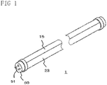
- FIG. 1 is a perspective view of a A straight tube type light emitting diode lamp according to an embodiment of the invention.
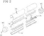
- FIG. 2 is an exploded perspective view of the A straight tube type light emitting diode lamp
- FIG. 3 is a cross-sectional view of the A straight tube type light emitting diode lamp taken along the section line A - A shown in FIG. 1 .
- the straight tube type light emitting diode lamp has a length and a diameter which replace the fittings of conventional lamps.
- the total length of the illumination lamp is the same as that of the conventional illumination lamp.
- the length can be appropriately set to 300 mm, 450mm, 600mm, 900mm, 1200mm, 1800mm, 2400mm or the like depending on the application.
- the diameter of the tube of the illuminating lamp is almost the same as that of the conventional fluorescent lamp.
- the illumination lamp has substantially the same external appearance and appearance as the conventional illumination lamp.
- the straight tube type light emitting diode lamp comprises an LED element 13, a substrate 12 for implementing the LED element, a heat sink 15, a second heat sink 17, a third heat sink 19, an LED controller, a cover 23, and an end cap 50.
- the second heat sink 17 and the third heat sink 19 are integrally molded.
- the cover 23 includes a translucent cover 31 for transmitting light from the LED element 13 and a first heat sink 33 coupled with the heat sink 15.
- the connection of the heat sink means that the two heat sinks are integrally molded, or they are in contact with each other so that heat is transmitted to the two heat sinks.
- a closed space is formed by the heat sink 15, the cover 23 and the end cap 50.
- the closed space accommodates the LED element 13, the substrate 12, the second heat sink 17, the third heat sink, and the like.
- the end cap 50 is fitted to the end of the tubular structure constituted by the heat sink 15 and the cover 23.
- the end cap 50 is provided with power supply pins.
- a plurality of LED elements 13 are arranged on the substrate 12 at equal intervals along the longitudinal direction.
- An LED controller 21 is arranged at the end of the substrate 12.
- the substrate 12 is accommodated and supported in the longitudinal internal space (closed space) of the second heat sink 17.
- the LED element 13 is disposed so that its light emitting surface faces the translucent cover 31 at the opening on the strike formed on the side of the translucent cover 31 of the second heat sink 17.
- the substrate has thermal conductivity.
- the second heat sink 17 transmits the heat generated from the LED element 13 to the third heat sink 19 via the substrate 12.
- the third heat sink 19 extends from one end of the coupling portion with the second heat sink 17 toward the translucent cover 31 and the other end is connected to the first heat sink 33.
- the LED element 13 is arranged on the center line 61 of the translucent cover 31 along the cross section.
- the substrate 12, the LED element 13, the second heat sink 17, the third heat sink 19, the translucent cover 31, and the first heat sink 33 are disposed in line symmetry with respect to the center line 61.
- the surface 19 a on the LED element 13 side of the third heat sink 19 has light reflection characteristics.
- the total reflectance of the surface 19 a of the third heat sink 19 is set to 80% or more in order to improve the light emission illuminance of the LED element 13 to be equal to or higher than that of the conventional fluorescent tube.
- the illuminance at this time is based on the "light brightness theorem” that the brightness is inversely proportional to the square of the distance between the light source and the irradiated surface ", the length S of the distance between the LED element 13 and the third heat sink 19 ls set to 1 to 1.5 mmT.
- the third heat sink 19 is disposed in a posture in which light from the LED element 13 is directed to the translucent cover 31.
- the third heat sink 19 forms an angle ⁇ with the surface of the substrate 12.
- the angle ⁇ is, for example, 30 to 70 degrees.
- the third heat sink 19 includes a first heat sink member 191 extending from the second heat sink 17 toward the translucent cover 31 and a second heat sink member 193.
- the second heat sink member 193 is coupled to the first heat sink 33 extending from the vicinity of the end opposite to the second heat sink 17 of a first heat sink member 191 so as to face the translucent cover.
- the surface 193 a of the second heat sink member 193 facing the translucent cover 31 has light reflection characteristics.
- the surface 193 a of the second heat sink member 193 has light reflection characteristics. As a result, in the light from the LED element 13, as shown in FIG. 4 , the light reflected on the inner surface of the translucent cover 31 is reflected by the surface 193 a and can passes through the translucent cover 31. By subjecting the surface 193 a to a treatment for increasing the reflection efficiency (silver coating or the like), the surface 193 a has enhanced radiation efficiency and reflection efficiency.
- the treatment for enhancing the reflection efficiency is silver coating, silver plating and the like. Silver paint can improve total reflectance by 90%. Further, matching between the reflecting material and the heat sink is unnecessary, and the quality is improved.
- reference numeral 85 is a heat sink.
- This heat sink 85 provides a high heat dissipation effect.
- the heat of the part touched by the human body can obtained a safe temperature (for example, 40 °C.).
- the heat sink material can use copper or aluminum which is excellent in heat conduction efficiency
- the illuminance of the structure shown in FIG. 3 is higher than the illuminance of the conventional structure shown in FIG. 5 .
- the illumination distribution can be set at a wide angle (140 degrees or more).
- the illumination lamp can realize the performance (illuminance and light distribution) of the conventional fluorescent lamp with 50% power consumption, so energy saving can be achieved.
- the illumination lamp does not generate high heat in a fluorescent tube, the illumination lamp obtains high safety.
- the second heat sink 17 and the third heat sink 19 can be drawn out using a mold alumite material. For this reason, the processing is simplified, so that cost reduction and shortening process can be obtained.
- the straight tube type light emitting diode lamp can make the surface temperature of the heat sink safe even when touched by the human body (about 40 ° C), which is the biggest problem of the LED, and the illuminance should be equal to or higher than that of the fluorescent lamp.
- the illumination lamp can set the illuminance distribution to a wide angle (140 degrees or more).
- the illumination lamp enables performance (illuminance and light distribution) of the conventional fluorescent lamp with 50% power consumption of the fluorescent lamp.
- the illumination lamp obtains an energy saving illumination light source.
- the power consumption can decrease from 1/2 to 1/3 compared to fluorescent lights, the illuminance and PPFD can be increased from 2 to 3 times.
- the illumination lamp does not generate high heat such as a fluorescent lamp and contributes to safety and security.
- the weight of the lighting lamp can be 500 g or less.
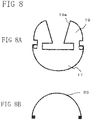
- FIG. 8 is a figure for explaining another embodiment of the illumination lamp.
- the shapes of the first to third heat sinks, the first heat sink material and the second heat sink material of the present invention are not limited to the above-described shapes.
- the second heat sink 17 and the third heat sink 19 may be configured as shown in FIG. 8 .
- the illumination lamp includes a light emitting diode, a translucent cover for transmitting the light from the light emitting diode, a first heat sink which accommodates a light emitting diode integrally formed with the translucent cover, a heat conducting substrate on which a light emitting diode is mounted, a second heat sink for supporting the substrate, and a third heat sink for transferring heat from the second heat sink to the first heat sink in a closed space.
- the third heat sink extends from the second heat sink toward the translucent cover and one end of the third heat sink is connected to the second and other end is connected to the first heat sink.
- the surface of light emitting diode in the third heat sink on the straight tube type light emitting diode lamp side has light reflection characteristics.
- the third heat sink is disposed in a posture directing light from the light emitting diode to the translucent cover.
- the third heat sink includes a first heat sink member extending from the second heat sink toward the translucent cover and a second heat sink member extending from the vicinity of an end portion opposite side from second heat sink of the first heat sink member on the opposite side from the second heat sink to face the translucent cover, And a second heat sink member is coupled to the first heat sink.
- the surface of the second heat sink member that faces the translucent cover has light reflection characteristics.
- the A straight tube type light emitting diode lamp is provided with a light emitting diode on the center line of the translucent cover along the cross section of the cylindrical closed space.
- the third heat sink is line symmetrical with respect to the center line.
Landscapes
- Engineering & Computer Science (AREA)
- General Engineering & Computer Science (AREA)
- Physics & Mathematics (AREA)
- Microelectronics & Electronic Packaging (AREA)
- Optics & Photonics (AREA)
- Non-Portable Lighting Devices Or Systems Thereof (AREA)
- Arrangement Of Elements, Cooling, Sealing, Or The Like Of Lighting Devices (AREA)
- Fastening Of Light Sources Or Lamp Holders (AREA)
Applications Claiming Priority (2)
| Application Number | Priority Date | Filing Date | Title |
|---|---|---|---|
| JP2014212768A JP5717114B1 (ja) | 2014-10-17 | 2014-10-17 | 直管形発光ダイオード式照明灯 |
| PCT/JP2015/066371 WO2016059826A1 (fr) | 2014-10-17 | 2015-06-05 | Lampe à diode luminescente de type tube droit |
Publications (2)
| Publication Number | Publication Date |
|---|---|
| EP3208521A1 true EP3208521A1 (fr) | 2017-08-23 |
| EP3208521A4 EP3208521A4 (fr) | 2018-02-28 |
Family
ID=53277381
Family Applications (1)
| Application Number | Title | Priority Date | Filing Date |
|---|---|---|---|
| EP15850865.5A Withdrawn EP3208521A4 (fr) | 2014-10-17 | 2015-06-05 | Lampe à diode luminescente de type tube droit |
Country Status (16)
| Country | Link |
|---|---|
| US (1) | US20170254485A1 (fr) |
| EP (1) | EP3208521A4 (fr) |
| JP (1) | JP5717114B1 (fr) |
| KR (1) | KR20170081639A (fr) |
| CN (1) | CN107110437B (fr) |
| AU (1) | AU2015331832A1 (fr) |
| BR (1) | BR112017007897A2 (fr) |
| CA (1) | CA2964703A1 (fr) |
| IL (1) | IL251702A0 (fr) |
| MX (1) | MX2017004938A (fr) |
| PH (1) | PH12017500707A1 (fr) |
| RU (1) | RU2017114954A (fr) |
| SG (1) | SG11201703046UA (fr) |
| TN (1) | TN2017000153A1 (fr) |
| TW (2) | TWI573960B (fr) |
| WO (1) | WO2016059826A1 (fr) |
Families Citing this family (5)
| Publication number | Priority date | Publication date | Assignee | Title |
|---|---|---|---|---|
| JPWO2017002960A1 (ja) * | 2015-07-02 | 2018-07-05 | 株式会社アブラム | 照明装置 |
| CN105065984A (zh) * | 2015-07-30 | 2015-11-18 | 东莞市闻誉实业有限公司 | Led灯具 |
| JP6727038B2 (ja) * | 2016-06-13 | 2020-07-22 | 三菱電機株式会社 | 光源ユニット及び照明装置 |
| JP2018056104A (ja) * | 2016-09-29 | 2018-04-05 | 株式会社アブラム | 発光ダイオード式照明装置 |
| JP2018056105A (ja) * | 2016-09-29 | 2018-04-05 | 株式会社アブラム | 発光ダイオード式照明装置 |
Family Cites Families (12)
| Publication number | Priority date | Publication date | Assignee | Title |
|---|---|---|---|---|
| TW205099B (fr) * | 1991-05-30 | 1993-05-01 | Mitsui Toatsu Chemicals | |
| EP1711739A4 (fr) * | 2004-01-28 | 2008-07-23 | Tir Technology Lp | Luminaire directement visible |
| US7976196B2 (en) * | 2008-07-09 | 2011-07-12 | Altair Engineering, Inc. | Method of forming LED-based light and resulting LED-based light |
| CN101839405A (zh) * | 2009-12-18 | 2010-09-22 | 深圳市成光兴实业发展有限公司 | 一种采用整体荧光转换技术的led日光灯 |
| JP5634757B2 (ja) * | 2010-06-14 | 2014-12-03 | 三菱電機照明株式会社 | 光源モジュール |
| CN101922638A (zh) * | 2010-08-24 | 2010-12-22 | 鸿富锦精密工业(深圳)有限公司 | Led日光灯 |
| TWI386592B (zh) * | 2010-08-30 | 2013-02-21 | Hon Hai Prec Ind Co Ltd | Led日光燈 |
| CN101956919A (zh) * | 2010-10-11 | 2011-01-26 | 鸿富锦精密工业(深圳)有限公司 | 发光二极管灯具 |
| JP2012216314A (ja) * | 2011-03-31 | 2012-11-08 | Fdk Corp | Led照明装置 |
| WO2012172697A1 (fr) * | 2011-06-17 | 2012-12-20 | イワタニエレクトロニクス株式会社 | Lampe d'éclairage à del |
| WO2015110306A1 (fr) * | 2014-01-22 | 2015-07-30 | Koninklijke Philips N.V. | Dispositif d'éclairage et luminaire |
| CN203731288U (zh) * | 2014-02-11 | 2014-07-23 | 立达信绿色照明股份有限公司 | Led日光灯 |
-
2014
- 2014-10-17 JP JP2014212768A patent/JP5717114B1/ja not_active Expired - Fee Related
-
2015
- 2015-06-05 EP EP15850865.5A patent/EP3208521A4/fr not_active Withdrawn
- 2015-06-05 WO PCT/JP2015/066371 patent/WO2016059826A1/fr not_active Ceased
- 2015-06-05 CA CA2964703A patent/CA2964703A1/fr not_active Abandoned
- 2015-06-05 AU AU2015331832A patent/AU2015331832A1/en not_active Abandoned
- 2015-06-05 US US15/519,825 patent/US20170254485A1/en not_active Abandoned
- 2015-06-05 KR KR1020177009622A patent/KR20170081639A/ko not_active Ceased
- 2015-06-05 BR BR112017007897-0A patent/BR112017007897A2/pt not_active IP Right Cessation
- 2015-06-05 MX MX2017004938A patent/MX2017004938A/es unknown
- 2015-06-05 TN TN2017000153A patent/TN2017000153A1/en unknown
- 2015-06-05 CN CN201580056315.0A patent/CN107110437B/zh not_active Expired - Fee Related
- 2015-06-05 SG SG11201703046UA patent/SG11201703046UA/en unknown
- 2015-06-05 RU RU2017114954A patent/RU2017114954A/ru not_active Application Discontinuation
- 2015-08-11 TW TW104126126A patent/TWI573960B/zh not_active IP Right Cessation
- 2015-08-11 TW TW105138132A patent/TW201710626A/zh unknown
-
2017
- 2017-04-12 IL IL251702A patent/IL251702A0/en unknown
- 2017-04-17 PH PH12017500707A patent/PH12017500707A1/en unknown
Also Published As
| Publication number | Publication date |
|---|---|
| TN2017000153A1 (en) | 2018-10-19 |
| TWI573960B (zh) | 2017-03-11 |
| JP5717114B1 (ja) | 2015-05-13 |
| CN107110437A (zh) | 2017-08-29 |
| CA2964703A1 (fr) | 2016-04-21 |
| AU2015331832A1 (en) | 2017-06-08 |
| BR112017007897A2 (pt) | 2018-01-23 |
| TW201602501A (zh) | 2016-01-16 |
| WO2016059826A1 (fr) | 2016-04-21 |
| EP3208521A4 (fr) | 2018-02-28 |
| KR20170081639A (ko) | 2017-07-12 |
| CN107110437B (zh) | 2019-04-02 |
| IL251702A0 (en) | 2017-06-29 |
| SG11201703046UA (en) | 2017-05-30 |
| MX2017004938A (es) | 2017-10-04 |
| TW201710626A (zh) | 2017-03-16 |
| JP2016081752A (ja) | 2016-05-16 |
| PH12017500707A1 (en) | 2017-10-09 |
| US20170254485A1 (en) | 2017-09-07 |
| RU2017114954A (ru) | 2018-11-19 |
Similar Documents
| Publication | Publication Date | Title |
|---|---|---|
| US20130083555A1 (en) | Lightung module and illuminant decice having the same | |
| EP3208521A1 (fr) | Lampe à diode luminescente de type tube droit | |
| JP6173476B2 (ja) | 改良型熱伝達装置を含む照明デバイス | |
| CN102853288A (zh) | 光学元件及具有该光学元件的发光装置 | |
| US20180149320A1 (en) | Light-emitting diode type lighting device | |
| JP6490753B2 (ja) | 照明装置 | |
| US20160273752A1 (en) | Luminaire with thermally-insulating fin guards and associated methods | |
| KR102047686B1 (ko) | 조명장치 | |
| EP3346180B1 (fr) | Nouvelle ampoule à del | |
| CN110023670A (zh) | 发光二极管式照明装置 | |
| JP2016081897A (ja) | 直管形発光ダイオード式照明灯およびそのケース | |
| WO2017002960A1 (fr) | Dispositif d'éclairage | |
| JP2013069884A (ja) | 照明装置 | |
| JP2017050266A (ja) | 発光ダイオード式照明装置 | |
| CN102147060B (zh) | 灯具 | |
| CN205746057U (zh) | 照明装置 | |
| JP2017050265A (ja) | 発光ダイオード式照明装置 | |
| CN203231148U (zh) | Led照明装置 | |
| TWI516719B (zh) | 燈具 | |
| TW201727138A (zh) | 發光二極體式照明裝置 | |
| WO2017000766A1 (fr) | Module de source de lumière à del | |
| GB2519948A (en) | Lamp or luminaire | |
| WO2018188069A1 (fr) | Source de lumière r7s utilisée pour la sortie de guidage de lumière | |
| TW201728852A (zh) | 發光二極體式照明裝置 | |
| TWM508010U (zh) | 發光二極體燈泡 |
Legal Events
| Date | Code | Title | Description |
|---|---|---|---|
| STAA | Information on the status of an ep patent application or granted ep patent |
Free format text: STATUS: THE INTERNATIONAL PUBLICATION HAS BEEN MADE |
|
| PUAI | Public reference made under article 153(3) epc to a published international application that has entered the european phase |
Free format text: ORIGINAL CODE: 0009012 |
|
| STAA | Information on the status of an ep patent application or granted ep patent |
Free format text: STATUS: REQUEST FOR EXAMINATION WAS MADE |
|
| 17P | Request for examination filed |
Effective date: 20170421 |
|
| AK | Designated contracting states |
Kind code of ref document: A1 Designated state(s): AL AT BE BG CH CY CZ DE DK EE ES FI FR GB GR HR HU IE IS IT LI LT LU LV MC MK MT NL NO PL PT RO RS SE SI SK SM TR |
|
| AX | Request for extension of the european patent |
Extension state: BA ME |
|
| DAV | Request for validation of the european patent (deleted) | ||
| DAX | Request for extension of the european patent (deleted) | ||
| A4 | Supplementary search report drawn up and despatched |
Effective date: 20180130 |
|
| RIC1 | Information provided on ipc code assigned before grant |
Ipc: F21V 7/00 20060101ALI20180124BHEP Ipc: F21V 29/70 20150101ALI20180124BHEP Ipc: F21K 9/68 20160101ALI20180124BHEP Ipc: F21V 29/503 20150101ALI20180124BHEP Ipc: F21V 19/00 20060101ALI20180124BHEP Ipc: F21S 2/00 20160101AFI20180124BHEP |
|
| STAA | Information on the status of an ep patent application or granted ep patent |
Free format text: STATUS: EXAMINATION IS IN PROGRESS |
|
| 17Q | First examination report despatched |
Effective date: 20181206 |
|
| STAA | Information on the status of an ep patent application or granted ep patent |
Free format text: STATUS: THE APPLICATION IS DEEMED TO BE WITHDRAWN |
|
| 18D | Application deemed to be withdrawn |
Effective date: 20190417 |