EP3208529A1 - Vorrichtung zur projektion eines lichtstrahls, die mit einer matrix von lichtquellen ausgestattet ist, leuchtmodul und kfz-scheinwerfer mit einer solchen vorrichtung - Google Patents
Vorrichtung zur projektion eines lichtstrahls, die mit einer matrix von lichtquellen ausgestattet ist, leuchtmodul und kfz-scheinwerfer mit einer solchen vorrichtung Download PDFInfo
- Publication number
- EP3208529A1 EP3208529A1 EP17156449.5A EP17156449A EP3208529A1 EP 3208529 A1 EP3208529 A1 EP 3208529A1 EP 17156449 A EP17156449 A EP 17156449A EP 3208529 A1 EP3208529 A1 EP 3208529A1
- Authority
- EP
- European Patent Office
- Prior art keywords
- light
- primary
- sources
- optical system
- diopter
- Prior art date
- Legal status (The legal status is an assumption and is not a legal conclusion. Google has not performed a legal analysis and makes no representation as to the accuracy of the status listed.)
- Granted
Links
Images



Classifications
-
- F—MECHANICAL ENGINEERING; LIGHTING; HEATING; WEAPONS; BLASTING
- F21—LIGHTING
- F21S—NON-PORTABLE LIGHTING DEVICES; SYSTEMS THEREOF; VEHICLE LIGHTING DEVICES SPECIALLY ADAPTED FOR VEHICLE EXTERIORS
- F21S41/00—Illuminating devices specially adapted for vehicle exteriors, e.g. headlamps
- F21S41/10—Illuminating devices specially adapted for vehicle exteriors, e.g. headlamps characterised by the light source
- F21S41/14—Illuminating devices specially adapted for vehicle exteriors, e.g. headlamps characterised by the light source characterised by the type of light source
- F21S41/141—Light emitting diodes [LED]
- F21S41/143—Light emitting diodes [LED] the main emission direction of the LED being parallel to the optical axis of the illuminating device
-
- F—MECHANICAL ENGINEERING; LIGHTING; HEATING; WEAPONS; BLASTING
- F21—LIGHTING
- F21S—NON-PORTABLE LIGHTING DEVICES; SYSTEMS THEREOF; VEHICLE LIGHTING DEVICES SPECIALLY ADAPTED FOR VEHICLE EXTERIORS
- F21S41/00—Illuminating devices specially adapted for vehicle exteriors, e.g. headlamps
- F21S41/10—Illuminating devices specially adapted for vehicle exteriors, e.g. headlamps characterised by the light source
- F21S41/14—Illuminating devices specially adapted for vehicle exteriors, e.g. headlamps characterised by the light source characterised by the type of light source
- F21S41/141—Light emitting diodes [LED]
-
- B—PERFORMING OPERATIONS; TRANSPORTING
- B60—VEHICLES IN GENERAL
- B60Q—ARRANGEMENT OF SIGNALLING OR LIGHTING DEVICES, THE MOUNTING OR SUPPORTING THEREOF OR CIRCUITS THEREFOR, FOR VEHICLES IN GENERAL
- B60Q1/00—Arrangement of optical signalling or lighting devices, the mounting or supporting thereof or circuits therefor
- B60Q1/02—Arrangement of optical signalling or lighting devices, the mounting or supporting thereof or circuits therefor the devices being primarily intended to illuminate the way ahead or to illuminate other areas of way or environments
- B60Q1/04—Arrangement of optical signalling or lighting devices, the mounting or supporting thereof or circuits therefor the devices being primarily intended to illuminate the way ahead or to illuminate other areas of way or environments the devices being headlights
- B60Q1/14—Arrangement of optical signalling or lighting devices, the mounting or supporting thereof or circuits therefor the devices being primarily intended to illuminate the way ahead or to illuminate other areas of way or environments the devices being headlights having dimming means
- B60Q1/1415—Dimming circuits
- B60Q1/1423—Automatic dimming circuits, i.e. switching between high beam and low beam due to change of ambient light or light level in road traffic
-
- F—MECHANICAL ENGINEERING; LIGHTING; HEATING; WEAPONS; BLASTING
- F21—LIGHTING
- F21S—NON-PORTABLE LIGHTING DEVICES; SYSTEMS THEREOF; VEHICLE LIGHTING DEVICES SPECIALLY ADAPTED FOR VEHICLE EXTERIORS
- F21S41/00—Illuminating devices specially adapted for vehicle exteriors, e.g. headlamps
- F21S41/10—Illuminating devices specially adapted for vehicle exteriors, e.g. headlamps characterised by the light source
- F21S41/14—Illuminating devices specially adapted for vehicle exteriors, e.g. headlamps characterised by the light source characterised by the type of light source
- F21S41/141—Light emitting diodes [LED]
- F21S41/151—Light emitting diodes [LED] arranged in one or more lines
- F21S41/153—Light emitting diodes [LED] arranged in one or more lines arranged in a matrix
-
- F—MECHANICAL ENGINEERING; LIGHTING; HEATING; WEAPONS; BLASTING
- F21—LIGHTING
- F21S—NON-PORTABLE LIGHTING DEVICES; SYSTEMS THEREOF; VEHICLE LIGHTING DEVICES SPECIALLY ADAPTED FOR VEHICLE EXTERIORS
- F21S41/00—Illuminating devices specially adapted for vehicle exteriors, e.g. headlamps
- F21S41/20—Illuminating devices specially adapted for vehicle exteriors, e.g. headlamps characterised by refractors, transparent cover plates, light guides or filters
-
- F—MECHANICAL ENGINEERING; LIGHTING; HEATING; WEAPONS; BLASTING
- F21—LIGHTING
- F21S—NON-PORTABLE LIGHTING DEVICES; SYSTEMS THEREOF; VEHICLE LIGHTING DEVICES SPECIALLY ADAPTED FOR VEHICLE EXTERIORS
- F21S41/00—Illuminating devices specially adapted for vehicle exteriors, e.g. headlamps
- F21S41/20—Illuminating devices specially adapted for vehicle exteriors, e.g. headlamps characterised by refractors, transparent cover plates, light guides or filters
- F21S41/25—Projection lenses
-
- F—MECHANICAL ENGINEERING; LIGHTING; HEATING; WEAPONS; BLASTING
- F21—LIGHTING
- F21S—NON-PORTABLE LIGHTING DEVICES; SYSTEMS THEREOF; VEHICLE LIGHTING DEVICES SPECIALLY ADAPTED FOR VEHICLE EXTERIORS
- F21S41/00—Illuminating devices specially adapted for vehicle exteriors, e.g. headlamps
- F21S41/20—Illuminating devices specially adapted for vehicle exteriors, e.g. headlamps characterised by refractors, transparent cover plates, light guides or filters
- F21S41/25—Projection lenses
- F21S41/255—Lenses with a front view of circular or truncated circular outline
-
- F—MECHANICAL ENGINEERING; LIGHTING; HEATING; WEAPONS; BLASTING
- F21—LIGHTING
- F21S—NON-PORTABLE LIGHTING DEVICES; SYSTEMS THEREOF; VEHICLE LIGHTING DEVICES SPECIALLY ADAPTED FOR VEHICLE EXTERIORS
- F21S41/00—Illuminating devices specially adapted for vehicle exteriors, e.g. headlamps
- F21S41/20—Illuminating devices specially adapted for vehicle exteriors, e.g. headlamps characterised by refractors, transparent cover plates, light guides or filters
- F21S41/25—Projection lenses
- F21S41/26—Elongated lenses
-
- F—MECHANICAL ENGINEERING; LIGHTING; HEATING; WEAPONS; BLASTING
- F21—LIGHTING
- F21S—NON-PORTABLE LIGHTING DEVICES; SYSTEMS THEREOF; VEHICLE LIGHTING DEVICES SPECIALLY ADAPTED FOR VEHICLE EXTERIORS
- F21S41/00—Illuminating devices specially adapted for vehicle exteriors, e.g. headlamps
- F21S41/20—Illuminating devices specially adapted for vehicle exteriors, e.g. headlamps characterised by refractors, transparent cover plates, light guides or filters
- F21S41/285—Refractors, transparent cover plates, light guides or filters not provided in groups F21S41/24 - F21S41/2805
-
- F—MECHANICAL ENGINEERING; LIGHTING; HEATING; WEAPONS; BLASTING
- F21—LIGHTING
- F21S—NON-PORTABLE LIGHTING DEVICES; SYSTEMS THEREOF; VEHICLE LIGHTING DEVICES SPECIALLY ADAPTED FOR VEHICLE EXTERIORS
- F21S41/00—Illuminating devices specially adapted for vehicle exteriors, e.g. headlamps
- F21S41/60—Illuminating devices specially adapted for vehicle exteriors, e.g. headlamps characterised by a variable light distribution
- F21S41/65—Illuminating devices specially adapted for vehicle exteriors, e.g. headlamps characterised by a variable light distribution by acting on light sources
- F21S41/663—Illuminating devices specially adapted for vehicle exteriors, e.g. headlamps characterised by a variable light distribution by acting on light sources by switching light sources
-
- F—MECHANICAL ENGINEERING; LIGHTING; HEATING; WEAPONS; BLASTING
- F21—LIGHTING
- F21V—FUNCTIONAL FEATURES OR DETAILS OF LIGHTING DEVICES OR SYSTEMS THEREOF; STRUCTURAL COMBINATIONS OF LIGHTING DEVICES WITH OTHER ARTICLES, NOT OTHERWISE PROVIDED FOR
- F21V19/00—Fastening of light sources or lamp holders
- F21V19/001—Fastening of light sources or lamp holders the light sources being semiconductors devices, e.g. LEDs
-
- F—MECHANICAL ENGINEERING; LIGHTING; HEATING; WEAPONS; BLASTING
- F21—LIGHTING
- F21W—INDEXING SCHEME ASSOCIATED WITH SUBCLASSES F21K, F21L, F21S and F21V, RELATING TO USES OR APPLICATIONS OF LIGHTING DEVICES OR SYSTEMS
- F21W2102/00—Exterior vehicle lighting devices for illuminating purposes
-
- F—MECHANICAL ENGINEERING; LIGHTING; HEATING; WEAPONS; BLASTING
- F21—LIGHTING
- F21Y—INDEXING SCHEME ASSOCIATED WITH SUBCLASSES F21K, F21L, F21S and F21V, RELATING TO THE FORM OR THE KIND OF THE LIGHT SOURCES OR OF THE COLOUR OF THE LIGHT EMITTED
- F21Y2101/00—Point-like light sources
-
- F—MECHANICAL ENGINEERING; LIGHTING; HEATING; WEAPONS; BLASTING
- F21—LIGHTING
- F21Y—INDEXING SCHEME ASSOCIATED WITH SUBCLASSES F21K, F21L, F21S and F21V, RELATING TO THE FORM OR THE KIND OF THE LIGHT SOURCES OR OF THE COLOUR OF THE LIGHT EMITTED
- F21Y2105/00—Planar light sources
- F21Y2105/10—Planar light sources comprising a two-dimensional [2D] array of point-like light-generating elements
-
- F—MECHANICAL ENGINEERING; LIGHTING; HEATING; WEAPONS; BLASTING
- F21—LIGHTING
- F21Y—INDEXING SCHEME ASSOCIATED WITH SUBCLASSES F21K, F21L, F21S and F21V, RELATING TO THE FORM OR THE KIND OF THE LIGHT SOURCES OR OF THE COLOUR OF THE LIGHT EMITTED
- F21Y2115/00—Light-generating elements of semiconductor light sources
- F21Y2115/10—Light-emitting diodes [LED]
Definitions
- the present invention relates to a light beam projection device, especially for a motor vehicle, and a beam light projector, of the low beam or high beam type, provided with such a projection device.
- an optical module of the housing notably comprises a light source, for example one (or more) electroluminescent diode (s), which emits light rays, and an optical system comprising one or more lenses and, if necessary a reflector, to orient the light rays from the light source to form the output light beam of the optical module.
- a light source for example one (or more) electroluminescent diode (s), which emits light rays
- an optical system comprising one or more lenses and, if necessary a reflector, to orient the light rays from the light source to form the output light beam of the optical module.
- some technologies can detect vehicles moving in the opposite direction, and project a light beam with a shadow zone.
- the projected beam has light holes towards the detected vehicle in order to avoid dazzling the driver of the crossed vehicle, while keeping a wide illumination on both sides of the vehicle.
- the light hole or holes follow the movement of the crossed vehicle; they move within the projected beam.
- the document DE 102008 061 556 discloses a lighting device provided with a matrix of light-emitting diodes, each diode being addressable individually. The diodes are arranged next to each other, each diode emitting a component of the light beam coming out of the projector. This device thus makes it possible to control the dimensions of the light beam by activating a portion of the light-emitting diodes corresponding to the size of the desired beam.
- the invention therefore aims to obtain an optical module configured to project a light beam whose dimensions and orientation are modifiable and whose light distribution is homogeneous.
- the invention relates to an optical device for projecting a light beam, especially for a motor vehicle, comprising upstream in the direction of propagation of the light rays, a matrix of primary sources of light capable of emitting light rays, and downstream a primary optical system provided with a plurality of converging optics configured to form virtual images of the primary sources of light, the virtual images being formed upstream of the matrix of primary sources of light, such that the dimensions of the virtual images are larger than the dimensions of the primary sources of light.
- the formation of virtual images makes it possible to obtain a better compactness along the optical axis of the device with respect to a device making a real image of the primary sources of light, downstream of the primary sources of light.
- the virtual images being formed upstream of the matrix of light sources, they are enlarged and thus minimize the interval between the beams produced by the different sources.
- the primary optical system is configured such that the virtual images are juxtaposed or substantially juxtaposed, thus achieving a good homogeneity of the light distribution.
- micro-diopter means diopters whose external dimensions are less than or equal to 5 times the dimensions of the primary source of associated light. They are usually in millimetric order of magnitude. Thus, for example, for an individual light emitting diode (LED) whose emitting surface is 1 mm side, the dimensions of the associated diopter will be inscribed in a square of 5 mm maximum side. If the primary source consists of a sub-matrix of LEDs, it is the dimensions of the sub-matrix that will be considered.
- LED light emitting diode
- the matrix of primary sources is understood to mean a set of primary sources arranged according to at least two columns by at least two lines, preferably at least ten columns by at least three lines.
- a sub-matrix is then called a set composed of at least two primary sources, arranged in line or in columns.
- a sub-matrix may include one line and two columns of diodes.
- it may comprise at least two lines and at least two columns of diodes.
- the source matrix used may consist of sub-matrices of several different sizes.
- the dioptres associated with the sources at the edge of the matrix, in particular at the lateral ends to be larger than the others in order to form a laterally and vertically elongated virtual image which will give a projected light pattern of more larger than the others, especially to produce an illumination of the sides of the road.
- the invention also relates to an optical module comprising such a projection device and projection means, such as a projection lens or a reflector, arranged downstream of the primary optical system. in the projection direction of the light beam, the projection means being able to project a light beam from the virtual images serving as light sources to the projection means which are focused on said virtual images.
- projection means such as a projection lens or a reflector
- This last characteristic of the invention is particularly interesting and advantageous. Indeed, the focusing of the projection means on the virtual images, in particular on the plane containing said virtual images, makes the projection optical module insensitive to the defects of the primary optical system: if the projection means are focused on the surface of the diopters, it is this surface which is imaged and therefore all its defects of realization which are made visible, which can generate defects of homogeneity or chromaticism in the projected light beam. In addition, this makes it possible to use a sub-matrix of light sources in association with the primary optics, each source being individually imaged.
- the invention also relates to a motor vehicle headlight provided with such an optical module.
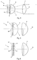
- the Figures 1 to 4 show a first embodiment of an optical module 1 for projecting a light beam, in particular for motor vehicle.
- the module 1 comprises from upstream to downstream in the direction of propagation of the light rays along the optical axis 15, a matrix 2 of primary sources 8 of light capable of emitting light rays, a primary optical system 4 which transmits the light rays , and projection means configured to project a light beam from the incident light rays transmitted by the primary optical system 4.
- the projection means take the form of a single projection lens 3.
- the projection means could nevertheless be formed by the combination of several lenses, several reflectors, or a combination of one or more lenses and / or one or more reflectors.
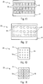
- the primary light sources 8 are, for example, electroluminescent diodes forming a network on the matrix 2, as shown in FIG. figure 2 . These arrays 2 of light emitting diodes are known and commercially available.
- the figure 11 shows a multi-chip array of light-emitting diode-type light sources 8, each source 8 being individually addressable. Each source 8 is manufactured separately on an independent chip, which is mounted on a holding element 18, itself assembled to the other sources on a support 17.
- figure 12 represents a second type of multi-chip matrix in which the light-emitting diodes are preassembled to each other on a common holding member disposed on a support 17.
- the Figures 13 and 14 illustrate single-chip matrices 20, in which the light sources 8 have an electrode in common.
- a diode has two electrodes 16, 19 in contact, a first point electrode 19 and a second surface electrode 16.
- the sources 8 are addressable individually by activating the first electrode 19, the second electrode being the same for all sources 8 of the chip.
- the light sources 8 of the figure 14 have a second electrode 19 divided into a portion so as to have a second independent electrode 19 for each source 8, the first electrodes 16 being simultaneously activatable.
- the light sub-matrices 20 may be based on a semiconductor light source comprising a plurality of submillimetric electroluminescent units, the units being distributed in different selectively activatable light zones.
- each of the submillimetric electroluminescent light units takes the form of a rod.
- the rods are on the same substrate, which preferably comprises silicon.
- the primary optical system 4 has the function of transmitting light rays of the diodes so that, combined with the projection means, here in the form of a projection lens 3, the beam projected outside the module, for example on the road, be homogeneous.
- the primary optical system 4 is provided with a plurality of convergent optics, which are preferably convergent input micro-diopters.
- the input micro-diopters 5 have a convex surface, that is to say they are bulged outwards towards the sources 8.
- the surface could however be flat, plano-convex or concave -convex.
- An input micro-diopter 5 is advantageously disposed downstream of each light source 8, that is to say from each light-emitting diode or submatrix of diodes of the matrix 2, as shown in FIG. figure 2 .
- the input micro-diopters 5 form virtual images 6 of the primary sources 8 of light, as shown in FIG. figure 3 .
- the virtual images 6 are formed upstream of the matrix 2 of primary sources 8, and thus serve as new light sources for the projection lens.
- the virtual images 6 obtained are enlarged and preferably substantially adjacent. In other words, they are not separated by significant space.
- the virtual virtual images may have a slight overlap between them, which will result in an overlap of their respective projections by the projection means measured on a screen placed at 25 m from the device which will preferably be less than 1 °.
- the edges of each virtual image will be fuzzy, so as to obtain this slight overlap which will ensure a good homogeneity of the generated light beam.
- the primary optical system 4 thus makes it possible to form virtual images 6 of the primary sources 8 of light in order to obtain a homogeneous distribution of the beam, that is to say that the components of the light beam are correctly adjusted relative to each other. other, with no dark and / or bright (overcurrent) bands between them that would interfere with driving comfort.
- the virtual images 6 are further away from the projection lens 3 with respect to the actual matrix of the light sources, which makes it possible to keep a compact optical module.
- the primary optical system 4 is advantageously configured to form virtual images 6 in a plane 61, the dimensions of the virtual images 6 being larger than the dimensions of the primary sources 8 of light. As shown in figure 4 , the enlargement of the size of the virtual images 6 allows a juxtaposition of the virtual images 6 in the plane 61 so as to be adjacent to each other. To this end, the curvature convex and the material component of the micro-diopter are adapted to the dimensions of the matrix 2 of primary sources 8, and the positioning of the primary optical system 4 relative to the matrix 2, so that the virtual images 6 are properly juxtaposed.
- the primary sources 8 of light are as close as possible to the primary optical system 4, for example at a distance of 0.2 to 2 mm, and preferably of 0.3 to 0.5 mm.
- the optical module 1 of the figure 4 comprises the matrix 2 of primary sources 8 of light, the primary optical system 4 provided with input micro-diopters 5 and projection means formed by the projection lens 3.
- the primary optical system 4 further comprises an output diopter 9 unique for all input micro-diopters 5.
- the output diopter 9 provides optical correction of the beam transmitted to the projection lens 3.
- the correction serves in particular to improve the optical efficiency of the device and to correct the optical aberrations of the system 4.
- the output diopter 9 has a substantially spherical dome shape. This shape deviates little the direction of the light rays of the beam coming from a source disposed on the optical axis 15, and which pass through the exit diopter 9.
- the output diopter 9 has a substantially spherical dome shape.
- the exit diopter 9 is wider than it is high.
- the output diopter 9 has in horizontal section - so in the direction of its width - a large radius of curvature, with an arrow of less than 5 mm.
- the surface in horizontal section may be convex or concave, that is to say that the output diopter 9 is respectively convergent or divergent, the latter alternative being particularly advantageous for reducing the size of the optical device.
- the surface of the output diopter 9 is aspherical, with a spherical approximation of the first order which has a radius of between 5 and 10 mm, limits included. .
- the primary optical system 4 is made of a single material.
- the input micro-diopters 5 and the output diopter 9 form the input and output faces of the same element, the primary optical system 4, which is similar to a complex lens.
- the primary optical system 4 comprises an output micro-diopter 9 for each input micro-diopter 5.
- the primary optical system 4 then forms a set of bi-convex microlenses, each microlens being arranged in front of a primary source of light.
- the microlens does not correct the transmitted overall beam, as a primary optical system 4 provided with a single output diopter 9.
- These microlenses are similar to those of the second variant of the second embodiment shown in FIG. figure 6 , described below. They have the advantage of bringing a better homogeneity of the virtual images and less deformation of the images.
- the device comprises several sub-matrices 20 of primary sources 8 of light, instead of the matrix 2 of the previous embodiment.
- Sub-matrices 20 of light-emitting diodes are more easily manipulated and less expensive than large matrices. So, he It is more economical to obtain a large matrix by associating several sub-matrices 20.
- Such a composition may contain from 100 to 600 light-emitting diodes.
- the light sub-matrices 20 may be based on a semiconductor light source comprising a plurality of submillimetric electroluminescent units, the units being distributed in different selectively activatable light zones.
- each of the submillimetric electroluminescent light units takes the form of a rod.
- the rods are on the same substrate, which preferably comprises silicon.
- the primary optical system 4 associates the light rays of the submatrices 20 to form a single beam having the same properties as in the embodiment provided with a single matrix.
- the invention therefore not only makes it possible to use standard components present on the market, but also avoids the problems of thermal expansion occurring on large components.
- the beams formed by the different sub-matrices 20 complement each other, with advantageously a slight superposition of the beams which does not exceed 1 ° opening angle of each beam. It is avoided to superpose the different beams with a larger angle in order to maintain a discretization of the components and keep a projected beam whose contours are well defined.
- the figure 5 shows a first embodiment of an optical projection module 1 comprising upstream several sub-matrices 20 and downstream, projection means 3 such as a projection lens.
- the optical device also comprises between the submatrices 20 and the lens 3, a primary optical system 4 provided with a plurality of convergent input micro-diopters 5, here having a convex surface, and configured to form virtual images 6 in the same plane 61.
- the micro-diopters of input 5 are arranged downstream of sub-matrices 20, an input micro-diopter 5 corresponding to a sub-matrix 20 of primary sources 8 of light.
- the virtual images 6 of the light sources are formed in the same plane 61, upstream of the sub-matrices 20, the virtual images 6 serving as light sources for the projection lens 3.
- the primary optical system 4 of the figure 5 has a single output diopter 9, formed to provide an optical correction of the beam transmitted to the projection lens 3, the exit diopter 9 also having a convex dome shape.
- the primary optical system 4 is also an optical element made of a single material.
- the primary optical system 4 comprises an output micro-diopter 9 for each input micro-diopter 5.
- the output diopter 9 does not have the function of correcting the transmitted beam.
- the primary optical system 4 then forms a set of bi-convex microlenses.
- the module comprises sub-matrices 20 of primary sources 8 of light, each bi-convex microlens being disposed downstream of a sub-matrix 20.
- the figure 7 shows a third variant of the second embodiment of the optical module 1 according to the invention, and which comprises a primary optical system 4 provided with input micro-diopters 5, arranged downstream of the submatrices 20 of primary sources 8 of light .
- a micro-diopter input 5 corresponds to a primary light source 8 of each submatrix 20.
- the primary optical system 4 comprises an output diopter 9 for each sub-matrix 20.
- the output diopter 9 and the micro-input dioptres 5 of each lens are in continuity of material, so that they form a complex lens.
- the complex lenses of the primary optical system 4 may further be connected to each other.
- the output diopter 9 generates an enlarged virtual image of the sub-matrix, so that the beams of each sub-matrix 20 are adjusted relative to each other.
- the output dioptres 9 and the input micro-diopters 5 are part of a primary optical system 4 integrally.
- the primary optical system 4 comprises only one element.
- the figure 8 describes a fourth variant of the second embodiment, which is similar to the third variant of the figure 7 , the difference residing in the primary optical system 4 which is separated into two elements 12, 13.
- the first element 12 comprises the input micro-diopters 5 and a single substantially flat output face for all input micro-diopters 5.
- the second element 13 is provided with an input face having a convex diopter 14 for each sub-matrix 20, and output diopters 9 also for each sub-matrix 20.
- the fifth variant of the figure 9 is substantially the same as the fourth variant.
- the shape of the first element 12 differs in that it comprises a set of bi-convex microlenses, similarly to the second variant of the figure 6 .
- Optical systems 4 of the third, fourth, and fifth variants are particularly suitable for sub-matrices 20 whose primary sources 8 of lights are distant from each other. A removal of more than 5% of the width of the primary source 8 of light can be considered as a significant distance.
- the input micro-diopters 5 placed downstream of each primary source 8 of light make it possible to homogenize, within a sub-matrix, according to the process described above, the light supplied by the primary sources 8
- the output dioptres 9 placed downstream of each submatrix 20 have the function of making a second virtual image located in a plane 11, homogeneous between the sub-matrices.
- the combination of the output diopter 9 and the input diopter 14 creates the virtual images between sub-matrices.
- this generates less geometric deformation of the image.
- This homogenization between the sub-matrices 20 is especially useful insofar as the distance between the sub-matrices is greater than that between the light sources 8.
Landscapes
- Engineering & Computer Science (AREA)
- General Engineering & Computer Science (AREA)
- Physics & Mathematics (AREA)
- Microelectronics & Electronic Packaging (AREA)
- Optics & Photonics (AREA)
- Mathematical Physics (AREA)
- Mechanical Engineering (AREA)
- Non-Portable Lighting Devices Or Systems Thereof (AREA)
- Led Device Packages (AREA)
Applications Claiming Priority (1)
| Application Number | Priority Date | Filing Date | Title |
|---|---|---|---|
| FR1651414A FR3048059B1 (fr) | 2016-02-22 | 2016-02-22 | Dispositif de projection de faisceau lumineux muni d'une matrice de sources de lumiere, module d'eclairage et projecteur muni d'un tel dispositif |
Publications (2)
| Publication Number | Publication Date |
|---|---|
| EP3208529A1 true EP3208529A1 (de) | 2017-08-23 |
| EP3208529B1 EP3208529B1 (de) | 2024-03-27 |
Family
ID=55752575
Family Applications (1)
| Application Number | Title | Priority Date | Filing Date |
|---|---|---|---|
| EP17156449.5A Active EP3208529B1 (de) | 2016-02-22 | 2017-02-16 | Vorrichtung zur projektion eines lichtstrahls, die mit einer matrix von lichtquellen ausgestattet ist, leuchtmodul und kfz-scheinwerfer mit einer solchen vorrichtung |
Country Status (6)
| Country | Link |
|---|---|
| US (1) | US10400972B2 (de) |
| EP (1) | EP3208529B1 (de) |
| JP (1) | JP6971584B2 (de) |
| KR (1) | KR102677698B1 (de) |
| CN (1) | CN107101154B (de) |
| FR (1) | FR3048059B1 (de) |
Cited By (4)
| Publication number | Priority date | Publication date | Assignee | Title |
|---|---|---|---|---|
| CN109027955A (zh) * | 2018-09-10 | 2018-12-18 | 常熟理工学院 | 一种智能汽车前照灯矩阵式照明单元 |
| EP3450829A1 (de) * | 2017-08-21 | 2019-03-06 | LG Electronics Inc. | Lampe für ein fahrzeuge sowie fahrzeug damit |
| FR3074256A1 (fr) * | 2017-11-28 | 2019-05-31 | Valeo Vision | Dispositif optique de projection de faisceau lumineux segmente muni d'un systeme optique de formation de segments lumineux. |
| US10955106B1 (en) * | 2019-09-27 | 2021-03-23 | Hyundai Mobis Co., Ltd. | Head lamp for vehicle |
Families Citing this family (29)
| Publication number | Priority date | Publication date | Assignee | Title |
|---|---|---|---|---|
| CN107091443B (zh) * | 2016-02-18 | 2019-10-18 | 株式会社小糸制作所 | 车辆用灯具 |
| JP6709651B2 (ja) * | 2016-03-24 | 2020-06-17 | 株式会社小糸製作所 | 車両用灯具、車両用灯具制御システムおよびこれらを備えた車両 |
| KR101795229B1 (ko) * | 2016-03-31 | 2017-11-08 | 현대자동차주식회사 | 차량용 램프 장치 |
| DE102017206956A1 (de) * | 2017-04-25 | 2018-10-25 | Osram Gmbh | Scheinwerfer mit clustern aus halbleiterlichtquellen |
| AT520488B1 (de) * | 2017-10-04 | 2019-07-15 | Zkw Group Gmbh | Fahrzeugscheinwerfer |
| KR102036749B1 (ko) * | 2017-12-14 | 2019-10-28 | 에스엘 주식회사 | 차량용 램프 |
| JP7042616B2 (ja) * | 2017-12-28 | 2022-03-28 | スタンレー電気株式会社 | 車両用灯具 |
| FR3077366B1 (fr) * | 2018-01-29 | 2020-01-17 | Valeo Vision | Module lumineux comportant un element optique primaire equipe de deux nappes de mise en forme |
| FR3079474B1 (fr) * | 2018-03-30 | 2020-10-02 | Valeo Vision | Systeme optique pour vehicule automobile |
| CN108224356B (zh) * | 2018-04-13 | 2020-02-04 | 华域视觉科技(上海)有限公司 | 车灯系统 |
| WO2019205900A1 (zh) * | 2018-04-25 | 2019-10-31 | 华域视觉科技(上海)有限公司 | 一种车辆用矩阵式照明装置 |
| CN108561846B (zh) * | 2018-04-25 | 2020-09-04 | 华域视觉科技(上海)有限公司 | 一种车辆用矩阵式照明装置 |
| CN110486689A (zh) * | 2018-05-15 | 2019-11-22 | 法雷奥照明公司 | 照明或信号指示装置和机动车辆 |
| CN108775547B (zh) * | 2018-07-25 | 2024-06-04 | 华域视觉科技(上海)有限公司 | 一种照明显示装置 |
| FR3084723B1 (fr) * | 2018-07-31 | 2020-08-28 | Valeo Vision | Module lumineux comportant une matrice de sources lumineuses et un systeme optique bifocal |
| DE102018217213A1 (de) * | 2018-10-09 | 2020-04-09 | Fraunhofer-Gesellschaft zur Förderung der angewandten Forschung e.V. | Fernlichtscheinwerfer |
| KR20200080838A (ko) * | 2018-12-27 | 2020-07-07 | 에스엘 주식회사 | 차량용 램프 |
| JP2020140822A (ja) * | 2019-02-27 | 2020-09-03 | 株式会社小糸製作所 | 車両用灯具 |
| WO2020233297A1 (zh) * | 2019-05-20 | 2020-11-26 | 华域视觉科技(上海)有限公司 | 车灯光学元件组件、车辆照明模组、车灯及车辆 |
| EP3786518A1 (de) * | 2019-08-27 | 2021-03-03 | Seoul Semiconductor Europe GmbH | Beleuchtungsvorrichtung |
| CN112443811A (zh) * | 2019-09-04 | 2021-03-05 | 华域视觉科技(上海)有限公司 | 一种车灯初级光学元件、车灯模组、车灯及车辆 |
| EP3835649A1 (de) * | 2019-12-12 | 2021-06-16 | T.Y.C. Brother Industrial Co., Ltd. | Adaptiver scheinwerfer für kfz |
| FR3106671B1 (fr) | 2019-12-20 | 2022-07-15 | Valeo Vision | Système de projection de faisceaux lumineux |
| EP3862623B1 (de) * | 2020-02-10 | 2022-11-02 | Lumileds LLC | Abbildungslinse zur verwendung in einem lichtmodul für einen fahrzeugscheinwerfer, lichtmodul und fahrzeugscheinwerfer |
| KR102822330B1 (ko) * | 2020-03-05 | 2025-06-19 | 현대모비스 주식회사 | 자동차용 램프 및 그 램프를 포함하는 자동차 |
| CN116457607B (zh) * | 2020-12-02 | 2026-01-02 | 艾迈斯-欧司朗股份有限公司 | 用于汽车前照灯的光学系统 |
| CN113503515B (zh) * | 2020-12-22 | 2025-02-25 | 华域视觉科技(上海)有限公司 | Adb车灯模组、车灯及车辆 |
| KR20230004148A (ko) * | 2021-06-30 | 2023-01-06 | 현대모비스 주식회사 | 차량용 램프 및 이를 포함하는 자동차 |
| FR3137438B1 (fr) | 2022-06-30 | 2024-07-26 | Valeo Vision | Module lumineux avec affichage par led optimisé pour application automobile |
Citations (8)
| Publication number | Priority date | Publication date | Assignee | Title |
|---|---|---|---|---|
| EP1213178A2 (de) * | 2000-12-06 | 2002-06-12 | Hella KG Hueck & Co. | Fahrzeugscheinwerfer |
| CN1948821A (zh) * | 2005-10-14 | 2007-04-18 | 斯坦雷电气株式会社 | 车辆用灯具 |
| DE102008061556A1 (de) | 2008-12-11 | 2009-09-24 | Daimler Ag | Beleuchtungseinrichtung für ein Fahrzeug |
| EP2357399A1 (de) * | 2010-02-16 | 2011-08-17 | Koito Manufacturing Co., Ltd. | Optische Einheit |
| EP2752615A1 (de) * | 2011-09-01 | 2014-07-09 | Koito Manufacturing Co., Ltd. | Automobilscheinwerfervorrichtung |
| EP2789900A2 (de) * | 2013-04-11 | 2014-10-15 | Automotive Lighting Reutlingen GmbH | Lichtmodul für eine Kraftfahrzeugbeleuchtungseinrichtung |
| EP2910847A2 (de) * | 2014-02-25 | 2015-08-26 | Automotive Lighting Reutlingen GmbH | Lichtmodul eines Kraftfahrzeugscheinwerfers und Scheinwerfer mit einem solchen Lichtmodul |
| DE102014210500A1 (de) * | 2014-06-03 | 2015-12-03 | Osram Gmbh | Optik für eine Fahrzeug-Beleuchtungseinrichtung |
Family Cites Families (18)
| Publication number | Priority date | Publication date | Assignee | Title |
|---|---|---|---|---|
| JP3839235B2 (ja) * | 2000-09-18 | 2006-11-01 | 株式会社小糸製作所 | 車両用灯具 |
| FR2899343B1 (fr) * | 2006-04-04 | 2008-09-05 | Commissariat Energie Atomique | Lentille a immersion solide a capacite de focalisation accrue |
| JP5075595B2 (ja) * | 2007-11-26 | 2012-11-21 | 株式会社東芝 | 表示装置及びそれを用いた移動体 |
| DE102008003006B4 (de) | 2008-01-02 | 2012-07-26 | Automotive Lighting Reutlingen Gmbh | Fahrzeugscheinwerfer mit verschwenkbarem Umlenkspiegel |
| JP2011165624A (ja) * | 2010-02-15 | 2011-08-25 | Yazaki Corp | 車両用バックライトユニット及び車両用表示装置 |
| JP5823211B2 (ja) * | 2011-09-01 | 2015-11-25 | 株式会社小糸製作所 | 車両用前照灯装置 |
| DE112012003685T5 (de) * | 2011-09-05 | 2014-07-10 | Mitsubishi Electric Corp. | Bildverarbeitungsvorrichtung und Bildverarbeitungsverfahren |
| DE102012202290B4 (de) * | 2012-02-15 | 2014-03-27 | Automotive Lighting Reutlingen Gmbh | Lichtmodul für ein blendungsfreies Kraftfahrzeug-Fernlicht |
| WO2013132530A1 (ja) * | 2012-03-06 | 2013-09-12 | 三菱電機株式会社 | 前照灯用光源および前照灯 |
| US8643950B2 (en) * | 2012-03-15 | 2014-02-04 | Blackberry Limited | Lens-based image augmenting optical window with intermediate real image |
| US9217552B2 (en) | 2012-07-27 | 2015-12-22 | Sharp Kabushiki Kaisha | Illumination device |
| FR2995973B1 (fr) * | 2012-09-25 | 2019-04-05 | Valeo Vision | Dispositif d'eclairage et/ou de signalisation pour vehicule comprenant une lentille et des sources |
| FR3000572B1 (fr) * | 2012-12-28 | 2016-04-29 | Valeo Etudes Electroniques | Dispositif de transmission d'images pour afficheur et afficheur tete haute equipe dudit dispositif |
| DE102013205487A1 (de) * | 2013-03-27 | 2014-10-02 | Automotive Lighting Reutlingen Gmbh | Kraftfahrzeugleuchte für dynamische Leuchtenfunktionen |
| JP2014202835A (ja) * | 2013-04-03 | 2014-10-27 | 三菱電機株式会社 | 照明装置及び画像表示装置 |
| DE102013214116C5 (de) * | 2013-07-18 | 2018-07-05 | Automotive Lighting Reutlingen Gmbh | Scheinwerfer für ein blendungsfreies Fernlicht |
| FR3012867A1 (fr) * | 2013-11-07 | 2015-05-08 | Valeo Vision | Element optique primaire, module lumineux et projecteur pour vehicule automobile |
| CN204740418U (zh) * | 2015-07-14 | 2015-11-04 | 中国科学院重庆绿色智能技术研究院 | 一种基于dmd的蓝光激发荧光粉式激光车灯 |
-
2016
- 2016-02-22 FR FR1651414A patent/FR3048059B1/fr active Active
-
2017
- 2017-02-16 EP EP17156449.5A patent/EP3208529B1/de active Active
- 2017-02-21 US US15/437,679 patent/US10400972B2/en active Active
- 2017-02-21 KR KR1020170022932A patent/KR102677698B1/ko active Active
- 2017-02-21 JP JP2017030078A patent/JP6971584B2/ja active Active
- 2017-02-22 CN CN201710098416.5A patent/CN107101154B/zh active Active
Patent Citations (8)
| Publication number | Priority date | Publication date | Assignee | Title |
|---|---|---|---|---|
| EP1213178A2 (de) * | 2000-12-06 | 2002-06-12 | Hella KG Hueck & Co. | Fahrzeugscheinwerfer |
| CN1948821A (zh) * | 2005-10-14 | 2007-04-18 | 斯坦雷电气株式会社 | 车辆用灯具 |
| DE102008061556A1 (de) | 2008-12-11 | 2009-09-24 | Daimler Ag | Beleuchtungseinrichtung für ein Fahrzeug |
| EP2357399A1 (de) * | 2010-02-16 | 2011-08-17 | Koito Manufacturing Co., Ltd. | Optische Einheit |
| EP2752615A1 (de) * | 2011-09-01 | 2014-07-09 | Koito Manufacturing Co., Ltd. | Automobilscheinwerfervorrichtung |
| EP2789900A2 (de) * | 2013-04-11 | 2014-10-15 | Automotive Lighting Reutlingen GmbH | Lichtmodul für eine Kraftfahrzeugbeleuchtungseinrichtung |
| EP2910847A2 (de) * | 2014-02-25 | 2015-08-26 | Automotive Lighting Reutlingen GmbH | Lichtmodul eines Kraftfahrzeugscheinwerfers und Scheinwerfer mit einem solchen Lichtmodul |
| DE102014210500A1 (de) * | 2014-06-03 | 2015-12-03 | Osram Gmbh | Optik für eine Fahrzeug-Beleuchtungseinrichtung |
Cited By (6)
| Publication number | Priority date | Publication date | Assignee | Title |
|---|---|---|---|---|
| EP3450829A1 (de) * | 2017-08-21 | 2019-03-06 | LG Electronics Inc. | Lampe für ein fahrzeuge sowie fahrzeug damit |
| US10598337B2 (en) | 2017-08-21 | 2020-03-24 | Zkw Group Gmbh | Lamp for vehicles and vehicle having the same |
| FR3074256A1 (fr) * | 2017-11-28 | 2019-05-31 | Valeo Vision | Dispositif optique de projection de faisceau lumineux segmente muni d'un systeme optique de formation de segments lumineux. |
| CN109027955A (zh) * | 2018-09-10 | 2018-12-18 | 常熟理工学院 | 一种智能汽车前照灯矩阵式照明单元 |
| CN109027955B (zh) * | 2018-09-10 | 2020-10-16 | 常熟理工学院 | 一种智能汽车前照灯矩阵式照明单元 |
| US10955106B1 (en) * | 2019-09-27 | 2021-03-23 | Hyundai Mobis Co., Ltd. | Head lamp for vehicle |
Also Published As
| Publication number | Publication date |
|---|---|
| KR20170098713A (ko) | 2017-08-30 |
| CN107101154B (zh) | 2021-11-19 |
| FR3048059A1 (fr) | 2017-08-25 |
| CN107101154A (zh) | 2017-08-29 |
| US10400972B2 (en) | 2019-09-03 |
| FR3048059B1 (fr) | 2022-08-05 |
| JP2017162800A (ja) | 2017-09-14 |
| KR102677698B1 (ko) | 2024-06-21 |
| EP3208529B1 (de) | 2024-03-27 |
| JP6971584B2 (ja) | 2021-11-24 |
| US20170241607A1 (en) | 2017-08-24 |
Similar Documents
| Publication | Publication Date | Title |
|---|---|---|
| EP3208529B1 (de) | Vorrichtung zur projektion eines lichtstrahls, die mit einer matrix von lichtquellen ausgestattet ist, leuchtmodul und kfz-scheinwerfer mit einer solchen vorrichtung | |
| EP3208530B1 (de) | Vorrichtung zur projektion eines lichtstrahls, die mit matrix von lichtquellen ausgestattet ist, leuchtmodul und kfz-scheinwerfer mit einer solchen vorrichtung | |
| EP3147557B1 (de) | Primäres optisches element für kraftfahrzeugsbeleuchtungsmodul | |
| EP3351990B1 (de) | Vorrichtung zur projektion eines verpixelten lichtstrahls, und mit einer solchen vorrichtung ausgestatteter scheinwerfer | |
| EP3604904B1 (de) | Lichtmodul, das eine matrix von lichtquellen und ein bifokales optisches system umfasst | |
| EP3350506B1 (de) | Lichtstrahlprojektionsvorrichtung eines kraftfahrzeugs und kraftfahrzeugscheinwerfer mit dieser vorrichtung | |
| EP3167226A1 (de) | Beleuchtungsmodul für ein kraftfahrzeug | |
| FR3039629A1 (fr) | Dispositif d'eclairage pour projecteur de vehicule automobile | |
| EP4285051B1 (de) | Kraftfahrzeugvorrichtung zur beleuchtung der strasse | |
| EP3453946A1 (de) | Leuchtmodul für kraftfahrzeug, und beleuchtungs- und/oder signalisierungsvorrichtung, die mit einem solchen modul ausgestattet ist | |
| FR3055947B1 (fr) | Systeme optique de vehicule automobile | |
| FR3074260A1 (fr) | Module lumineux pour vehicule automobile, et dispositif d'eclairage et/ou de signalisation muni d'un tel module | |
| EP3517830B1 (de) | Strassenbeleuchtungsvorrichtung mit kontrollierter kaustik erzeugender oberfläche, die einen lichtstrahl bildet | |
| EP3857283A1 (de) | Optisches projektionssystem und leuchtmodul für ein fahrzeug | |
| EP3502550A1 (de) | Segmentierter lichtstrahl, der beleuchtungsfunktionen erfüllt | |
| WO2022269095A1 (fr) | Module optique d'un système lumineux d'un véhicule automobile | |
| FR3074256A1 (fr) | Dispositif optique de projection de faisceau lumineux segmente muni d'un systeme optique de formation de segments lumineux. | |
| FR3077117A1 (fr) | Module lumineux pour vehicule automobile, et dispositif d'eclairage et/ou de signalisation muni d'un tel module | |
| WO2024175414A1 (fr) | Dispositif d'éclairage | |
| EP4724729A1 (de) | Beleuchtungsmodul für ein kraftfahrzeug | |
| WO2025168791A1 (fr) | Module lumineux | |
| EP3276249B1 (de) | Leuchtsystem für beleuchtungsvorrichtung und optional für signalvorrichtung für kraftfahrzeug | |
| EP4639017A1 (de) | Beleuchtungsmodul für ein kraftfahrzeug | |
| FR3130939A1 (fr) | Module de projection d’image lumineuse dynamique | |
| FR3139881A1 (fr) | Module lumineux |
Legal Events
| Date | Code | Title | Description |
|---|---|---|---|
| PUAI | Public reference made under article 153(3) epc to a published international application that has entered the european phase |
Free format text: ORIGINAL CODE: 0009012 |
|
| STAA | Information on the status of an ep patent application or granted ep patent |
Free format text: STATUS: THE APPLICATION HAS BEEN PUBLISHED |
|
| AK | Designated contracting states |
Kind code of ref document: A1 Designated state(s): AL AT BE BG CH CY CZ DE DK EE ES FI FR GB GR HR HU IE IS IT LI LT LU LV MC MK MT NL NO PL PT RO RS SE SI SK SM TR |
|
| AX | Request for extension of the european patent |
Extension state: BA ME |
|
| STAA | Information on the status of an ep patent application or granted ep patent |
Free format text: STATUS: REQUEST FOR EXAMINATION WAS MADE |
|
| 17P | Request for examination filed |
Effective date: 20180201 |
|
| RBV | Designated contracting states (corrected) |
Designated state(s): AL AT BE BG CH CY CZ DE DK EE ES FI FR GB GR HR HU IE IS IT LI LT LU LV MC MK MT NL NO PL PT RO RS SE SI SK SM TR |
|
| STAA | Information on the status of an ep patent application or granted ep patent |
Free format text: STATUS: EXAMINATION IS IN PROGRESS |
|
| 17Q | First examination report despatched |
Effective date: 20210510 |
|
| P01 | Opt-out of the competence of the unified patent court (upc) registered |
Effective date: 20230528 |
|
| REG | Reference to a national code |
Ref country code: DE Free format text: PREVIOUS MAIN CLASS: F21S0008100000 Ref country code: DE Ref legal event code: R079 Ref document number: 602017080324 Country of ref document: DE Free format text: PREVIOUS MAIN CLASS: F21S0008100000 Ipc: F21S0041143000 |
|
| GRAP | Despatch of communication of intention to grant a patent |
Free format text: ORIGINAL CODE: EPIDOSNIGR1 |
|
| STAA | Information on the status of an ep patent application or granted ep patent |
Free format text: STATUS: GRANT OF PATENT IS INTENDED |
|
| RIC1 | Information provided on ipc code assigned before grant |
Ipc: F21S 41/663 20180101ALI20231113BHEP Ipc: F21S 41/20 20180101ALI20231113BHEP Ipc: F21S 41/26 20180101ALI20231113BHEP Ipc: F21S 41/255 20180101ALI20231113BHEP Ipc: F21S 41/25 20180101ALI20231113BHEP Ipc: F21S 41/153 20180101ALI20231113BHEP Ipc: F21Y 101/00 20160101ALI20231113BHEP Ipc: F21Y 105/10 20160101ALI20231113BHEP Ipc: F21Y 115/10 20160101ALI20231113BHEP Ipc: F21V 5/04 20060101ALI20231113BHEP Ipc: F21S 41/143 20180101AFI20231113BHEP |
|
| INTG | Intention to grant announced |
Effective date: 20231215 |
|
| GRAS | Grant fee paid |
Free format text: ORIGINAL CODE: EPIDOSNIGR3 |
|
| GRAA | (expected) grant |
Free format text: ORIGINAL CODE: 0009210 |
|
| STAA | Information on the status of an ep patent application or granted ep patent |
Free format text: STATUS: THE PATENT HAS BEEN GRANTED |
|
| AK | Designated contracting states |
Kind code of ref document: B1 Designated state(s): AL AT BE BG CH CY CZ DE DK EE ES FI FR GB GR HR HU IE IS IT LI LT LU LV MC MK MT NL NO PL PT RO RS SE SI SK SM TR |
|
| REG | Reference to a national code |
Ref country code: GB Ref legal event code: FG4D Free format text: NOT ENGLISH |
|
| REG | Reference to a national code |
Ref country code: CH Ref legal event code: EP |
|
| REG | Reference to a national code |
Ref country code: DE Ref legal event code: R096 Ref document number: 602017080324 Country of ref document: DE |
|
| REG | Reference to a national code |
Ref country code: IE Ref legal event code: FG4D Free format text: LANGUAGE OF EP DOCUMENT: FRENCH |
|
| PG25 | Lapsed in a contracting state [announced via postgrant information from national office to epo] |
Ref country code: LT Free format text: LAPSE BECAUSE OF FAILURE TO SUBMIT A TRANSLATION OF THE DESCRIPTION OR TO PAY THE FEE WITHIN THE PRESCRIBED TIME-LIMIT Effective date: 20240327 |
|
| REG | Reference to a national code |
Ref country code: LT Ref legal event code: MG9D |
|
| PG25 | Lapsed in a contracting state [announced via postgrant information from national office to epo] |
Ref country code: GR Free format text: LAPSE BECAUSE OF FAILURE TO SUBMIT A TRANSLATION OF THE DESCRIPTION OR TO PAY THE FEE WITHIN THE PRESCRIBED TIME-LIMIT Effective date: 20240628 |
|
| PG25 | Lapsed in a contracting state [announced via postgrant information from national office to epo] |
Ref country code: RS Free format text: LAPSE BECAUSE OF FAILURE TO SUBMIT A TRANSLATION OF THE DESCRIPTION OR TO PAY THE FEE WITHIN THE PRESCRIBED TIME-LIMIT Effective date: 20240627 Ref country code: HR Free format text: LAPSE BECAUSE OF FAILURE TO SUBMIT A TRANSLATION OF THE DESCRIPTION OR TO PAY THE FEE WITHIN THE PRESCRIBED TIME-LIMIT Effective date: 20240327 |
|
| PG25 | Lapsed in a contracting state [announced via postgrant information from national office to epo] |
Ref country code: RS Free format text: LAPSE BECAUSE OF FAILURE TO SUBMIT A TRANSLATION OF THE DESCRIPTION OR TO PAY THE FEE WITHIN THE PRESCRIBED TIME-LIMIT Effective date: 20240627 Ref country code: NO Free format text: LAPSE BECAUSE OF FAILURE TO SUBMIT A TRANSLATION OF THE DESCRIPTION OR TO PAY THE FEE WITHIN THE PRESCRIBED TIME-LIMIT Effective date: 20240627 Ref country code: LT Free format text: LAPSE BECAUSE OF FAILURE TO SUBMIT A TRANSLATION OF THE DESCRIPTION OR TO PAY THE FEE WITHIN THE PRESCRIBED TIME-LIMIT Effective date: 20240327 Ref country code: HR Free format text: LAPSE BECAUSE OF FAILURE TO SUBMIT A TRANSLATION OF THE DESCRIPTION OR TO PAY THE FEE WITHIN THE PRESCRIBED TIME-LIMIT Effective date: 20240327 Ref country code: GR Free format text: LAPSE BECAUSE OF FAILURE TO SUBMIT A TRANSLATION OF THE DESCRIPTION OR TO PAY THE FEE WITHIN THE PRESCRIBED TIME-LIMIT Effective date: 20240628 Ref country code: FI Free format text: LAPSE BECAUSE OF FAILURE TO SUBMIT A TRANSLATION OF THE DESCRIPTION OR TO PAY THE FEE WITHIN THE PRESCRIBED TIME-LIMIT Effective date: 20240327 Ref country code: BG Free format text: LAPSE BECAUSE OF FAILURE TO SUBMIT A TRANSLATION OF THE DESCRIPTION OR TO PAY THE FEE WITHIN THE PRESCRIBED TIME-LIMIT Effective date: 20240327 |
|
| REG | Reference to a national code |
Ref country code: NL Ref legal event code: MP Effective date: 20240327 |
|
| PG25 | Lapsed in a contracting state [announced via postgrant information from national office to epo] |
Ref country code: SE Free format text: LAPSE BECAUSE OF FAILURE TO SUBMIT A TRANSLATION OF THE DESCRIPTION OR TO PAY THE FEE WITHIN THE PRESCRIBED TIME-LIMIT Effective date: 20240327 Ref country code: LV Free format text: LAPSE BECAUSE OF FAILURE TO SUBMIT A TRANSLATION OF THE DESCRIPTION OR TO PAY THE FEE WITHIN THE PRESCRIBED TIME-LIMIT Effective date: 20240327 |
|
| PG25 | Lapsed in a contracting state [announced via postgrant information from national office to epo] |
Ref country code: NL Free format text: LAPSE BECAUSE OF FAILURE TO SUBMIT A TRANSLATION OF THE DESCRIPTION OR TO PAY THE FEE WITHIN THE PRESCRIBED TIME-LIMIT Effective date: 20240327 |
|
| REG | Reference to a national code |
Ref country code: AT Ref legal event code: MK05 Ref document number: 1670238 Country of ref document: AT Kind code of ref document: T Effective date: 20240327 |
|
| PG25 | Lapsed in a contracting state [announced via postgrant information from national office to epo] |
Ref country code: NL Free format text: LAPSE BECAUSE OF FAILURE TO SUBMIT A TRANSLATION OF THE DESCRIPTION OR TO PAY THE FEE WITHIN THE PRESCRIBED TIME-LIMIT Effective date: 20240327 |
|
| PG25 | Lapsed in a contracting state [announced via postgrant information from national office to epo] |
Ref country code: IS Free format text: LAPSE BECAUSE OF FAILURE TO SUBMIT A TRANSLATION OF THE DESCRIPTION OR TO PAY THE FEE WITHIN THE PRESCRIBED TIME-LIMIT Effective date: 20240727 |
|
| PG25 | Lapsed in a contracting state [announced via postgrant information from national office to epo] |
Ref country code: PT Free format text: LAPSE BECAUSE OF FAILURE TO SUBMIT A TRANSLATION OF THE DESCRIPTION OR TO PAY THE FEE WITHIN THE PRESCRIBED TIME-LIMIT Effective date: 20240729 Ref country code: SM Free format text: LAPSE BECAUSE OF FAILURE TO SUBMIT A TRANSLATION OF THE DESCRIPTION OR TO PAY THE FEE WITHIN THE PRESCRIBED TIME-LIMIT Effective date: 20240327 |
|
| PG25 | Lapsed in a contracting state [announced via postgrant information from national office to epo] |
Ref country code: ES Free format text: LAPSE BECAUSE OF FAILURE TO SUBMIT A TRANSLATION OF THE DESCRIPTION OR TO PAY THE FEE WITHIN THE PRESCRIBED TIME-LIMIT Effective date: 20240327 |
|
| PG25 | Lapsed in a contracting state [announced via postgrant information from national office to epo] |
Ref country code: CZ Free format text: LAPSE BECAUSE OF FAILURE TO SUBMIT A TRANSLATION OF THE DESCRIPTION OR TO PAY THE FEE WITHIN THE PRESCRIBED TIME-LIMIT Effective date: 20240327 Ref country code: EE Free format text: LAPSE BECAUSE OF FAILURE TO SUBMIT A TRANSLATION OF THE DESCRIPTION OR TO PAY THE FEE WITHIN THE PRESCRIBED TIME-LIMIT Effective date: 20240327 |
|
| PG25 | Lapsed in a contracting state [announced via postgrant information from national office to epo] |
Ref country code: AT Free format text: LAPSE BECAUSE OF FAILURE TO SUBMIT A TRANSLATION OF THE DESCRIPTION OR TO PAY THE FEE WITHIN THE PRESCRIBED TIME-LIMIT Effective date: 20240327 |
|
| PG25 | Lapsed in a contracting state [announced via postgrant information from national office to epo] |
Ref country code: PL Free format text: LAPSE BECAUSE OF FAILURE TO SUBMIT A TRANSLATION OF THE DESCRIPTION OR TO PAY THE FEE WITHIN THE PRESCRIBED TIME-LIMIT Effective date: 20240327 |
|
| PG25 | Lapsed in a contracting state [announced via postgrant information from national office to epo] |
Ref country code: SK Free format text: LAPSE BECAUSE OF FAILURE TO SUBMIT A TRANSLATION OF THE DESCRIPTION OR TO PAY THE FEE WITHIN THE PRESCRIBED TIME-LIMIT Effective date: 20240327 |
|
| PG25 | Lapsed in a contracting state [announced via postgrant information from national office to epo] |
Ref country code: SM Free format text: LAPSE BECAUSE OF FAILURE TO SUBMIT A TRANSLATION OF THE DESCRIPTION OR TO PAY THE FEE WITHIN THE PRESCRIBED TIME-LIMIT Effective date: 20240327 Ref country code: SK Free format text: LAPSE BECAUSE OF FAILURE TO SUBMIT A TRANSLATION OF THE DESCRIPTION OR TO PAY THE FEE WITHIN THE PRESCRIBED TIME-LIMIT Effective date: 20240327 Ref country code: RO Free format text: LAPSE BECAUSE OF FAILURE TO SUBMIT A TRANSLATION OF THE DESCRIPTION OR TO PAY THE FEE WITHIN THE PRESCRIBED TIME-LIMIT Effective date: 20240327 Ref country code: PT Free format text: LAPSE BECAUSE OF FAILURE TO SUBMIT A TRANSLATION OF THE DESCRIPTION OR TO PAY THE FEE WITHIN THE PRESCRIBED TIME-LIMIT Effective date: 20240729 Ref country code: PL Free format text: LAPSE BECAUSE OF FAILURE TO SUBMIT A TRANSLATION OF THE DESCRIPTION OR TO PAY THE FEE WITHIN THE PRESCRIBED TIME-LIMIT Effective date: 20240327 Ref country code: IS Free format text: LAPSE BECAUSE OF FAILURE TO SUBMIT A TRANSLATION OF THE DESCRIPTION OR TO PAY THE FEE WITHIN THE PRESCRIBED TIME-LIMIT Effective date: 20240727 Ref country code: ES Free format text: LAPSE BECAUSE OF FAILURE TO SUBMIT A TRANSLATION OF THE DESCRIPTION OR TO PAY THE FEE WITHIN THE PRESCRIBED TIME-LIMIT Effective date: 20240327 Ref country code: EE Free format text: LAPSE BECAUSE OF FAILURE TO SUBMIT A TRANSLATION OF THE DESCRIPTION OR TO PAY THE FEE WITHIN THE PRESCRIBED TIME-LIMIT Effective date: 20240327 Ref country code: CZ Free format text: LAPSE BECAUSE OF FAILURE TO SUBMIT A TRANSLATION OF THE DESCRIPTION OR TO PAY THE FEE WITHIN THE PRESCRIBED TIME-LIMIT Effective date: 20240327 Ref country code: AT Free format text: LAPSE BECAUSE OF FAILURE TO SUBMIT A TRANSLATION OF THE DESCRIPTION OR TO PAY THE FEE WITHIN THE PRESCRIBED TIME-LIMIT Effective date: 20240327 |
|
| PG25 | Lapsed in a contracting state [announced via postgrant information from national office to epo] |
Ref country code: IT Free format text: LAPSE BECAUSE OF FAILURE TO SUBMIT A TRANSLATION OF THE DESCRIPTION OR TO PAY THE FEE WITHIN THE PRESCRIBED TIME-LIMIT Effective date: 20240327 |
|
| PG25 | Lapsed in a contracting state [announced via postgrant information from national office to epo] |
Ref country code: IT Free format text: LAPSE BECAUSE OF FAILURE TO SUBMIT A TRANSLATION OF THE DESCRIPTION OR TO PAY THE FEE WITHIN THE PRESCRIBED TIME-LIMIT Effective date: 20240327 |
|
| REG | Reference to a national code |
Ref country code: DE Ref legal event code: R097 Ref document number: 602017080324 Country of ref document: DE |
|
| PG25 | Lapsed in a contracting state [announced via postgrant information from national office to epo] |
Ref country code: DK Free format text: LAPSE BECAUSE OF FAILURE TO SUBMIT A TRANSLATION OF THE DESCRIPTION OR TO PAY THE FEE WITHIN THE PRESCRIBED TIME-LIMIT Effective date: 20240327 |
|
| PG25 | Lapsed in a contracting state [announced via postgrant information from national office to epo] |
Ref country code: DK Free format text: LAPSE BECAUSE OF FAILURE TO SUBMIT A TRANSLATION OF THE DESCRIPTION OR TO PAY THE FEE WITHIN THE PRESCRIBED TIME-LIMIT Effective date: 20240327 |
|
| PLBE | No opposition filed within time limit |
Free format text: ORIGINAL CODE: 0009261 |
|
| STAA | Information on the status of an ep patent application or granted ep patent |
Free format text: STATUS: NO OPPOSITION FILED WITHIN TIME LIMIT |
|
| 26N | No opposition filed |
Effective date: 20250103 |
|
| PG25 | Lapsed in a contracting state [announced via postgrant information from national office to epo] |
Ref country code: SI Free format text: LAPSE BECAUSE OF FAILURE TO SUBMIT A TRANSLATION OF THE DESCRIPTION OR TO PAY THE FEE WITHIN THE PRESCRIBED TIME-LIMIT Effective date: 20240327 |
|
| PG25 | Lapsed in a contracting state [announced via postgrant information from national office to epo] |
Ref country code: MC Free format text: LAPSE BECAUSE OF FAILURE TO SUBMIT A TRANSLATION OF THE DESCRIPTION OR TO PAY THE FEE WITHIN THE PRESCRIBED TIME-LIMIT Effective date: 20240327 |
|
| REG | Reference to a national code |
Ref country code: CH Ref legal event code: PL |
|
| PG25 | Lapsed in a contracting state [announced via postgrant information from national office to epo] |
Ref country code: LU Free format text: LAPSE BECAUSE OF NON-PAYMENT OF DUE FEES Effective date: 20250216 |
|
| PG25 | Lapsed in a contracting state [announced via postgrant information from national office to epo] |
Ref country code: CH Free format text: LAPSE BECAUSE OF NON-PAYMENT OF DUE FEES Effective date: 20250228 |
|
| GBPC | Gb: european patent ceased through non-payment of renewal fee |
Effective date: 20250216 |
|
| REG | Reference to a national code |
Ref country code: BE Ref legal event code: MM Effective date: 20250228 |
|
| PG25 | Lapsed in a contracting state [announced via postgrant information from national office to epo] |
Ref country code: GB Free format text: LAPSE BECAUSE OF NON-PAYMENT OF DUE FEES Effective date: 20250216 |
|
| PG25 | Lapsed in a contracting state [announced via postgrant information from national office to epo] |
Ref country code: BE Free format text: LAPSE BECAUSE OF NON-PAYMENT OF DUE FEES Effective date: 20250228 |
|
| PG25 | Lapsed in a contracting state [announced via postgrant information from national office to epo] |
Ref country code: IE Free format text: LAPSE BECAUSE OF NON-PAYMENT OF DUE FEES Effective date: 20250216 |
|
| PGFP | Annual fee paid to national office [announced via postgrant information from national office to epo] |
Ref country code: DE Payment date: 20260206 Year of fee payment: 10 |
|
| PGFP | Annual fee paid to national office [announced via postgrant information from national office to epo] |
Ref country code: FR Payment date: 20260227 Year of fee payment: 10 |