EP3208547B1 - Unité extérieure pour système de conditionnement d'air à fentes multiples à récupération de chaleur, et système de conditionnement d'air à fentes multiples à récupération de chaleur - Google Patents
Unité extérieure pour système de conditionnement d'air à fentes multiples à récupération de chaleur, et système de conditionnement d'air à fentes multiples à récupération de chaleur Download PDFInfo
- Publication number
- EP3208547B1 EP3208547B1 EP16799184.3A EP16799184A EP3208547B1 EP 3208547 B1 EP3208547 B1 EP 3208547B1 EP 16799184 A EP16799184 A EP 16799184A EP 3208547 B1 EP3208547 B1 EP 3208547B1
- Authority
- EP
- European Patent Office
- Prior art keywords
- way valve
- valve
- port
- refrigerant
- connector
- Prior art date
- Legal status (The legal status is an assumption and is not a legal conclusion. Google has not performed a legal analysis and makes no representation as to the accuracy of the status listed.)
- Active
Links
Images
Classifications
-
- F—MECHANICAL ENGINEERING; LIGHTING; HEATING; WEAPONS; BLASTING
- F24—HEATING; RANGES; VENTILATING
- F24F—AIR-CONDITIONING; AIR-HUMIDIFICATION; VENTILATION; USE OF AIR CURRENTS FOR SCREENING
- F24F1/00—Room units for air-conditioning, e.g. separate or self-contained units or units receiving primary air from a central station
- F24F1/06—Separate outdoor units, e.g. outdoor unit to be linked to a separate room comprising a compressor and a heat exchanger
- F24F1/08—Compressors specially adapted for separate outdoor units
- F24F1/10—Arrangement or mounting thereof
-
- F—MECHANICAL ENGINEERING; LIGHTING; HEATING; WEAPONS; BLASTING
- F25—REFRIGERATION OR COOLING; COMBINED HEATING AND REFRIGERATION SYSTEMS; HEAT PUMP SYSTEMS; MANUFACTURE OR STORAGE OF ICE; LIQUEFACTION SOLIDIFICATION OF GASES
- F25B—REFRIGERATION MACHINES, PLANTS OR SYSTEMS; COMBINED HEATING AND REFRIGERATION SYSTEMS; HEAT PUMP SYSTEMS
- F25B40/00—Subcoolers, desuperheaters or superheaters
- F25B40/04—Desuperheaters
-
- F—MECHANICAL ENGINEERING; LIGHTING; HEATING; WEAPONS; BLASTING
- F24—HEATING; RANGES; VENTILATING
- F24F—AIR-CONDITIONING; AIR-HUMIDIFICATION; VENTILATION; USE OF AIR CURRENTS FOR SCREENING
- F24F1/00—Room units for air-conditioning, e.g. separate or self-contained units or units receiving primary air from a central station
- F24F1/06—Separate outdoor units, e.g. outdoor unit to be linked to a separate room comprising a compressor and a heat exchanger
-
- F—MECHANICAL ENGINEERING; LIGHTING; HEATING; WEAPONS; BLASTING
- F24—HEATING; RANGES; VENTILATING
- F24F—AIR-CONDITIONING; AIR-HUMIDIFICATION; VENTILATION; USE OF AIR CURRENTS FOR SCREENING
- F24F1/00—Room units for air-conditioning, e.g. separate or self-contained units or units receiving primary air from a central station
- F24F1/06—Separate outdoor units, e.g. outdoor unit to be linked to a separate room comprising a compressor and a heat exchanger
- F24F1/14—Heat exchangers specially adapted for separate outdoor units
- F24F1/16—Arrangement or mounting thereof
-
- F—MECHANICAL ENGINEERING; LIGHTING; HEATING; WEAPONS; BLASTING
- F24—HEATING; RANGES; VENTILATING
- F24F—AIR-CONDITIONING; AIR-HUMIDIFICATION; VENTILATION; USE OF AIR CURRENTS FOR SCREENING
- F24F11/00—Control or safety arrangements
- F24F11/89—Arrangement or mounting of control or safety devices
-
- F—MECHANICAL ENGINEERING; LIGHTING; HEATING; WEAPONS; BLASTING
- F24—HEATING; RANGES; VENTILATING
- F24F—AIR-CONDITIONING; AIR-HUMIDIFICATION; VENTILATION; USE OF AIR CURRENTS FOR SCREENING
- F24F3/00—Air-conditioning systems in which conditioned primary air is supplied from one or more central stations to distributing units in the rooms or spaces where it may receive secondary treatment; Apparatus specially designed for such systems
- F24F3/12—Air-conditioning systems in which conditioned primary air is supplied from one or more central stations to distributing units in the rooms or spaces where it may receive secondary treatment; Apparatus specially designed for such systems characterised by the treatment of the air otherwise than by heating and cooling
- F24F3/14—Air-conditioning systems in which conditioned primary air is supplied from one or more central stations to distributing units in the rooms or spaces where it may receive secondary treatment; Apparatus specially designed for such systems characterised by the treatment of the air otherwise than by heating and cooling by humidification; by dehumidification
- F24F3/147—Air-conditioning systems in which conditioned primary air is supplied from one or more central stations to distributing units in the rooms or spaces where it may receive secondary treatment; Apparatus specially designed for such systems characterised by the treatment of the air otherwise than by heating and cooling by humidification; by dehumidification with both heat and humidity transfer between supplied and exhausted air
-
- F—MECHANICAL ENGINEERING; LIGHTING; HEATING; WEAPONS; BLASTING
- F25—REFRIGERATION OR COOLING; COMBINED HEATING AND REFRIGERATION SYSTEMS; HEAT PUMP SYSTEMS; MANUFACTURE OR STORAGE OF ICE; LIQUEFACTION SOLIDIFICATION OF GASES
- F25B—REFRIGERATION MACHINES, PLANTS OR SYSTEMS; COMBINED HEATING AND REFRIGERATION SYSTEMS; HEAT PUMP SYSTEMS
- F25B13/00—Compression machines, plants or systems, with reversible cycle
-
- F—MECHANICAL ENGINEERING; LIGHTING; HEATING; WEAPONS; BLASTING
- F25—REFRIGERATION OR COOLING; COMBINED HEATING AND REFRIGERATION SYSTEMS; HEAT PUMP SYSTEMS; MANUFACTURE OR STORAGE OF ICE; LIQUEFACTION SOLIDIFICATION OF GASES
- F25B—REFRIGERATION MACHINES, PLANTS OR SYSTEMS; COMBINED HEATING AND REFRIGERATION SYSTEMS; HEAT PUMP SYSTEMS
- F25B29/00—Combined heating and refrigeration systems, e.g. operating alternately or simultaneously
- F25B29/003—Combined heating and refrigeration systems, e.g. operating alternately or simultaneously of the compression type system
-
- F—MECHANICAL ENGINEERING; LIGHTING; HEATING; WEAPONS; BLASTING
- F25—REFRIGERATION OR COOLING; COMBINED HEATING AND REFRIGERATION SYSTEMS; HEAT PUMP SYSTEMS; MANUFACTURE OR STORAGE OF ICE; LIQUEFACTION SOLIDIFICATION OF GASES
- F25B—REFRIGERATION MACHINES, PLANTS OR SYSTEMS; COMBINED HEATING AND REFRIGERATION SYSTEMS; HEAT PUMP SYSTEMS
- F25B39/00—Evaporators; Condensers
- F25B39/02—Evaporators
- F25B39/028—Evaporators having distributing means
-
- F—MECHANICAL ENGINEERING; LIGHTING; HEATING; WEAPONS; BLASTING
- F25—REFRIGERATION OR COOLING; COMBINED HEATING AND REFRIGERATION SYSTEMS; HEAT PUMP SYSTEMS; MANUFACTURE OR STORAGE OF ICE; LIQUEFACTION SOLIDIFICATION OF GASES
- F25B—REFRIGERATION MACHINES, PLANTS OR SYSTEMS; COMBINED HEATING AND REFRIGERATION SYSTEMS; HEAT PUMP SYSTEMS
- F25B41/00—Fluid-circulation arrangements
- F25B41/20—Disposition of valves, e.g. of on-off valves or flow control valves
-
- F—MECHANICAL ENGINEERING; LIGHTING; HEATING; WEAPONS; BLASTING
- F25—REFRIGERATION OR COOLING; COMBINED HEATING AND REFRIGERATION SYSTEMS; HEAT PUMP SYSTEMS; MANUFACTURE OR STORAGE OF ICE; LIQUEFACTION SOLIDIFICATION OF GASES
- F25B—REFRIGERATION MACHINES, PLANTS OR SYSTEMS; COMBINED HEATING AND REFRIGERATION SYSTEMS; HEAT PUMP SYSTEMS
- F25B41/00—Fluid-circulation arrangements
- F25B41/20—Disposition of valves, e.g. of on-off valves or flow control valves
- F25B41/24—Arrangement of shut-off valves for disconnecting a part of the refrigerant cycle, e.g. an outdoor part
-
- F—MECHANICAL ENGINEERING; LIGHTING; HEATING; WEAPONS; BLASTING
- F25—REFRIGERATION OR COOLING; COMBINED HEATING AND REFRIGERATION SYSTEMS; HEAT PUMP SYSTEMS; MANUFACTURE OR STORAGE OF ICE; LIQUEFACTION SOLIDIFICATION OF GASES
- F25B—REFRIGERATION MACHINES, PLANTS OR SYSTEMS; COMBINED HEATING AND REFRIGERATION SYSTEMS; HEAT PUMP SYSTEMS
- F25B2313/00—Compression machines, plants or systems with reversible cycle not otherwise provided for
- F25B2313/025—Compression machines, plants or systems with reversible cycle not otherwise provided for using multiple outdoor units
- F25B2313/0253—Compression machines, plants or systems with reversible cycle not otherwise provided for using multiple outdoor units in parallel arrangements
Definitions
- the present disclosure relates to a technical field of refrigeration devices, and specifically, more particularly to an outdoor unit for a heat recovery VRF air conditioning system and a heat recovery VRF air conditioning system.
- a heat recovery VRF (Variable Refrigerant Flow) air conditioning system becomes increasingly popular in the market.
- a refrigerant contained in an outdoor unit serving as an evaporator is less than that contained in the outdoor unit serving as a condenser when in a cooling mode, and the redundant refrigerant is usually stored in a gas-liquid separator.
- the refrigerant is throttled and depressurized by a throttling element in a refrigerant flow direction switching device, and then forms a gas-liquid two-phase refrigerant to enter a pipe; more gaseous refrigerant is stored in the pipe, so that the amount of the refrigerant stored in the pipe is little, while more liquid refrigerant is stored in the gas-liquid separator, and even overflows the gas-liquid separator, which directly results in a drop of a suction-superheat degree of the compressor.
- an exhaust port of the compressor is usually in communication with a gas return port thereof via a hot gas bypass solenoid valve.
- the hot gas bypass solenoid valve is opened to increase the suction-superheat degree, which however directly reduces energy efficiency of the heat recovery VRF air conditioning system.
- a target condensation temperature and a target evaporation temperature are changed in accordance with the load of a load-side unit as determined using a load detection means, and the operating frequency of a compressor and the rotational speed of a blower are controlled so that the condensation temperature determined using a temperature detection means matches the target condensation temperature, and so that the evaporation temperature determined using the temperature detection means matches the target evaporation temperature.
- the present disclosure seeks to solve at least one of the problems existing in the related art to at least some extent.
- one objective of the present invention is to provide an outdoor unit for a heat recovery VRF air conditioning system, which is conductive to obtaining a suction-superheat degree of a compressor, and meanwhile improves energy efficiency of the heat recovery VRF air conditioning system.
- Another objective of the present invention is to provide a heat recovery VRF air conditioning system, including the above-described outdoor unit.
- the outdoor unit for the heat recovery VRF air conditioning system is defined in claim 1.
- the outdoor unit has a first connector and a second connector, and includes: a compressor having an exhaust port and a gas return port; a reversing assembly having a first valve port, a second valve port, a third valve port and a fourth valve port, in which the first valve port is connected to the exhaust port, the second valve port is connected to the gas return port, and the third valve port is connected to the first connector; an outdoor heat exchanger, having a first end connected to the fourth valve port, and a second end connected to the second connector; a plurality of one-way valves, in which each one-way valve has a circulation end and a stop end, and each one-way valve is opened only in one direction from the circulation end to the stop end; the plurality of one-way valves includes a first one-way valve, a second one-way valve, a third one-way valve, a fourth one-way valve, a fifth one-way valve and a sixth one
- the outdoor unit when the heat recovery VRF air conditioning system is in a heating mode, all of the throttling elements in the refrigerant flow direction switching device are opened, the refrigerant is throttled and depressurized by the throttling element connected in series between the third one-way valve and the outdoor heat exchanger before the refrigerant enters the outdoor heat exchanger, such that pressure of the two-phase refrigerant in the pipe is improved and dryness thereof is reduced, and hence more refrigerant may be stored in the pipe to reduce the amount of the refrigerant stored in the gas-liquid separator, which improves the suction-superheat degree of the compressor, and meanwhile improve the energy efficiency of the heat recovery VRF air conditioning system.
- the outdoor heat exchanger includes a plurality of first heat exchange passages arranged successively in an up-and-down direction, and a first control valve for controlling a refrigerant to flow or stop is connected in series between a first end of each first heat exchange passage and the first one-way valve.
- the outdoor unit for the heat recovery VRF air conditioning system includes a plurality of seventh one-way valves, the plurality of seventh one-way valves are provided in one to one correspondence with the plurality of first heat exchange passages, a circulation end of each seventh one-way valve is connected to a second end of the corresponding first heat exchange passage, and a stop end of each seventh one-way valve is connected to the sixth one-way valve.
- the outdoor heat exchanger includes a second heat exchange passage located at the lowest portion thereof, two ends of the second heat exchange passage are connected to the exhaust port and the second connector respectively, and a second control valve for controlling the refrigerant to flow or stop is connected in series between the second heat exchange passage and the exhaust port.
- the throttling element is an electronic expansion valve.
- the outdoor unit for the heat recovery VRF air conditioning system further includes a gas supplement passage, two ends of the gas supplement passage are connected to the exhaust port and the second connector respectively, and a third control valve for controlling the refrigerant to flow or stop is connected to the gas supplement passage in series.
- the third control valve is a solenoid valve.
- the outdoor unit for the heat recovery VRF air conditioning system further includes an oil separator, the oil separator comprises a first inlet, a refrigerant outlet and an oil outlet, the first inlet is connected to the exhaust port, the refrigerant outlet is connected to the first valve port, and the oil outlet is connected to the gas return port.
- the oil separator comprises a first inlet, a refrigerant outlet and an oil outlet, the first inlet is connected to the exhaust port, the refrigerant outlet is connected to the first valve port, and the oil outlet is connected to the gas return port.
- a heat recovery VRF air conditioning system includes the above-described outdoor unit.
- the heat recovery VRF air conditioning system by providing the above-described outdoor unit for the heat recovery VRF air conditioning system, may improve the suction-superheat degree of the compressor, and meanwhile improve the energy efficiency of the heat recovery VRF air conditioning system.
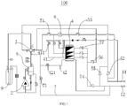
- Fig. 1 is a schematic view of an outdoor unit according to an embodiment of the present invention
- first and second are used herein for purposes of description and are not intended to indicate or imply relative importance or significance or to imply the number of indicated technical features.
- the feature defined with “first” and “second” may comprise one or more of this feature.
- a plurality of' means two or more than two, unless specified otherwise.
- the terms “mounted,” “connected,” “coupled,” “fixed” and the like are used broadly, and may be, for example, fixed connections, detachable connections, or integral connections; may also be mechanical or electrical connections; may also be direct connections or indirect connections via intervening structures; may also be inner communications or interactions of two elements, which can be understood by those skilled in the art according to specific situations.
- the outdoor unit 100 has a first connector 11 and a second connector 12, and the outdoor unit 100 is assembled with a refrigerant flow direction switching device and a plurality of indoor units via the first connector 11 and the second connector 12 to form the heat recovery VRF air conditioning system for adjusting indoor temperature.
- the heat recovery VRF air conditioning system has a pure cooling mode, a main cooling mode, a main heating mode and a pure heating mode.
- the pure cooling mode refers that all of the operating indoor units perform cooling; the pure heating mode refers that all of the operating indoor units perform heating; the main cooling mode refers that part of indoor units perform cooling and another part of indoor units perform heating, cooling load is greater than heating load, and the outdoor heat exchanger 4 is served as a condenser; the main heating mode refers that part of indoor units perform heating and another part of indoor units perform cooling, heating load is greater than cooling load, and the outdoor heat exchanger 4 is served as a evaporator.
- a heating mode in embodiments of the present invention includes the main heating mode and the pure heating mode, and a cooling mode includes the main cooling mode and the pure cooling mode.
- the outdoor unit 100 for the heat recovery VRF air conditioning system includes a compressor 2, a reversing assembly 3, the outdoor heat exchanger 4, a plurality of one-way valves, a throttling element 6 and a gas-liquid separator 9, in which the compressor 2 has an exhaust port a and a gas return port b.
- the structure and working principle of the compressor 2 are well known in the related art, and thus will not be described in detail herein.
- the reversing assembly 3 has a first valve port c, a second valve port d, a third valve port e and a fourth valve port f, in which the first valve port c is in communication with one of the third valve port e and the fourth valve port f, and the second valve port d is in communication with the other of the third valve port e and the fourth valve port f. That is to say, when the first valve port c is in communication with the third valve port e, the second valve port d is in communication with the fourth valve port f, and when the first valve port c is in communication with the fourth valve port f, the second valve port d is in communication with the third valve port e.
- the reversing assembly 3 is a four-way valve, but it should be understood that the reversing assembly 3 may also be formed as other structures, as long as the structure has the first valve port c, the second valve port d, the third valve port e, and the fourth valve port f, and meanwhile has a direction reversing function.
- the first valve port c is connected to the exhaust port a
- the second valve port d is connected to the gas return port b
- the third valve port e is connected to the first connector 11
- a first end of the outdoor heat exchanger 4 is connected to the fourth valve port f
- a second end of the outdoor heat exchanger 4 is connected to the second connector 12.
- the outdoor unit 100 may further include a fan for directing wind to the outdoor heat exchanger 4 to improve heat exchange efficiency of the outdoor heat exchanger 4.
- Each one-way valve has a circulation end and a stop end, and each one-way valve is opened only in one direction from the circulation end to the stop end, that is to say, the refrigerant only may enter the one-way valve via the circulation end and flow out via the stop end of the one-way valve, and not the other way around, such that the one-way valve has an effect that it may be opened only in one direction.
- the plurality of one-way valves include a first one-way valve 51, a second one-way valve 52, a third one-way valve 53, a fourth one-way valve 54, a fifth one-way valve 55 and a sixth one-way valve 56.
- the circulation end of the first one-way valve 51 is connected to the fourth valve port f, and the stop end of the first one-way valve 51 is connected to the first end of the outdoor heat exchanger 4.
- the refrigerant may only flow from the fourth valve port f to the first end of the outdoor heat exchanger 4, rather than flow from the first end of the outdoor heat exchanger 4 to the fourth valve port f.
- the circulation end of the second one-way valve 52 is connected to the first connector 11, and the stop end of the second one-way valve 52 is connected to the third valve port e.
- the refrigerant may only flow from the first connector 11 to the third valve port e, rather than flow from the third valve port e to the first connector 11.
- the circulation end of the third one-way valve 53 is connected between the second one-way valve 52 and the first connector 11, and the stop end of the third one-way valve 53 is connected to the first end of the outdoor heat exchanger 4.
- the refrigerant may only flow from the first connector 11 to the first end of the outdoor heat exchanger 4, rather than flow from the first end of the outdoor heat exchanger 4 to the first connector 11.
- the circulation end of the fourth one-way valve 54 is connected to the second end of the outdoor heat exchanger 4, and the stop end of the fourth one-way valve 54 is connected to the second connector 12, thus, by providing the fourth one-way valve 54, the refrigerant may only flow from the second end of the outdoor heat exchanger 4 to the second connector 12, while may not flow from the second connector 12 to the second end of the outdoor heat exchanger 4.
- the circulation end of the fifth one-way valve 55 is connected between the second one-way valve 52 and the third valve port e, and the stop end of the fifth one-way valve 55 is connected between the fourth one-way valve 54 and the second connector 12.
- the refrigerant may only flow from the third valve port e to the second connector 12, rather than flow from the second connector 12 to the third valve port e.
- the circulation end of the sixth one-way valve 56 is connected between the fourth one-way valve 54 and the outdoor heat exchanger 4, and the stop end of the sixth one-way valve 56 is connected between the first one-way valve 51 and the fourth valve port f.
- the refrigerant may only flow from the second end of the outdoor heat exchanger 4 to the fourth valve port f, rather than flow from the fourth valve port f to the second end of outdoor heat exchanger 4.
- the gas-liquid separator 9 includes a second inlet j and a gas outlet k, the second inlet j is connected to the second valve port d, and the gas outlet k is connected to the gas return port b.
- the refrigerant discharged from the second valve port d enters the gas-liquid separator 9 and undergoes gas-liquid separation therein, and the separated gaseous refrigerant may be discharged from the gas outlet k to the compressor 2, while the liquid refrigerant may be stored in the gas-liquid separator 9, such that a liquid impact phenomenon of the compressor 2 is avoided, and operational reliability of the outdoor unit 100 is improved.
- the throttling element 6 is connected in series between the third one-way valve 53 and the outdoor heat exchanger 4; when the VRF air conditioning system is in the heating mode, all of the throttling elements in the refrigerant flow direction switching device are opened, and the refrigerant is throttled and depressurized by the throttling element 6 before the refrigerant enters the outdoor heat exchanger 4, such that pressure of the two-phase refrigerant in the pipe is improved and dryness thereof is reduced, so as to increase the amount of the refrigerant in the pipe and further reduce the amount of the refrigerant stored in the gas-liquid separator 9, which improves a suction-superheat degree of the compressor 2, and meanwhile improves energy efficiency of the heat recovery VRF air conditioning system.
- the outdoor unit 100 has two modes: when the heat recovery VRF air conditioning system is in the pure cooling mode, the outdoor unit 100 operates in a first mode; and when the heat recovery VRF air conditioning system is in the pure heating mode, the outdoor unit 100 operates in a second mode.
- the outdoor unit 100 operates in the first mode or in the second mode according to a judgment about the system.
- the first valve port c of the reversing assembly 3 is in communication with the fourth valve port f
- the second valve port d is in communication with the third valve port e
- the refrigerant flow direction of the heat recovery VRF air conditioning system is in such a way: the compressor 2-the first valve port c of the reversing assembly 3-the fourth valve port f of the reversing assembly 3-the first one-way valve 51-the outdoor heat exchanger 4-the fourth one-way valve 54-the second connector 12-the refrigerant flow direction switching device-the indoor units-the first connector 11-the second one-way valve 52-the third valve port e of the reversing assembly 3-the second valve port d of the reversing assembly 3-the compressor 2.
- the first valve port c of the reversing assembly 3 is in communication with the third valve port e
- the second valve port d is in communication with the fourth valve port f
- the refrigerant flow direction of the heat recovery VRF air conditioning system is in such a way: the compressor 2-the first valve port c of the reversing assembly 3-the third valve port e of the reversing assembly 3-the fifth one-way valve 55-the second connector 12-the refrigerant flow direction switching device-the indoor units-the first connector 11-the third one-way valve 53-the throttling element 6-the outdoor heat exchanger 4-the sixth one-way valve 56-the fourth valve port f of the reversing assembly 3-the second valve port d of the reversing assembly 3-the compressor 2.
- the gaseous refrigerant with high temperature and high pressure discharged from the outdoor unit 100 first enters the heating indoor units through the refrigerant flow direction switching device and is condensed into the liquid refrigerant with high temperature and high pressure; then, the refrigerant is divided into two parts, in which a first part flows into the cooling indoor units to be vaporized, and a second part flows into the refrigerant flow direction switching device to be throttled; and then the two parts are merged, and throttled and depressurized by the throttling element 6 before flowing back into the outdoor heat exchanger 4, then flow back into the outdoor heat exchanger 4 to be vaporized, and finally flow back into the compressor 2 again.
- the outdoor unit 100 outputs a mixture of the gaseous refrigerant and the liquid refrigerant into the refrigerant flow direction switching device, and after the gas-liquid separation conducted by the refrigerant flow direction switching device, the superheated gaseous refrigerant enters the heating indoor units to perform heating, and the subcooled liquid refrigerant enters the cooling indoor units to perform refrigerating; when the heat recovery VRF air conditioning system is in the pure heating mode or in the main heating mode, the outdoor unit 100 outputs the gaseous refrigerant with high temperature and high pressure; when the heat recovery VRF air conditioning system is in the pure cooling mode, the outdoor unit 100 outputs the liquid refrigerant.
- the first through sixth one-way valves 51-56 not only have an effect of flow path separation, but
- the outdoor unit 100 for the heat recovery VRF air conditioning system when the heat recovery VRF air conditioning system is in the heating mode, all of the throttling elements in the refrigerant flow direction switching device are opened, the refrigerant is throttled and depressurized by the throttling element 6 connected in series between the third one-way valve 53 and the outdoor heat exchanger 4 before the refrigerant enters the outdoor heat exchanger 4, such that the pressure of the two-phase refrigerant in the pipe is improved and the dryness thereof is reduced, and more refrigerant may be stored in the pipe to reduce the amount of the refrigerant stored in the gas-liquid separator 9, which improves the suction-superheat degree of the compressor 2, reduces energy consumption of the compressor, and meanwhile improves the energy efficiency of the heat recovery VRF air conditioning system.
- the outdoor heat exchanger 4 includes a plurality of first heat exchange passages 41 arranged successively in an up-and-down direction, and a first control valve 411 for controlling the refrigerant to flow or stop is connected in series between a first end of each first heat exchange passage 41 and the first one-way valve 51. That is to say, a use state of each first heat exchange passage 41 is controlled by the corresponding first control valve 411, and first heat exchange passages 41 are independent from each other.
- each first control valve 411 may be a solenoid valve.
- the outdoor unit 100 further includes a plurality of seventh one-way valves 57, the plurality of seventh one-way valves 57 are provided in one to one correspondence with the plurality of first heat exchange passages 41, the circulation end of each seventh one-way valve 57 is connected to a second end of the corresponding first heat exchange passage 41, and the stop end of each seventh one-way valve 57 is connected to the sixth one-way valve 56.
- one first heat exchange passage 41 corresponds to one seventh one-way valve 57
- the refrigerant may enter the seventh one-way valve 57 only via the circulation end of the seventh one-way valve 57, and flow out via the stop end of the seventh one-way valve 57, but may not enter the seventh one-way valve 57 via the stop end of the seventh one-way valve 57.
- the refrigerant may only flow from the first heat exchange passage 41 to the sixth one-way valve 56, rather than flow from the sixth one-way valve 56 to the first heat exchange passage 41, which further ensures the operational reliability of the outdoor unit 100.
- the outdoor heat exchanger 4 further includes a second heat exchange passage 42 located at the lowest portion thereof, two ends of the second heat exchange passage 42 are connected to the exhaust port a and the second connector 12 respectively, and a second control valve 421 for controlling the refrigerant to flow or stop is connected in series between the second heat exchange passage 42 and the exhaust port a. That is to say, when the second control valve 421 controls the refrigerant to flow, the refrigerant in the compressor 2 may be directly discharged from the exhaust port a into the second heat exchange passage 42 to perform heat exchange, and the refrigerant is discharged from the second connector 12 into the refrigerant flow direction switching device after the heat exchange.
- the refrigerant with high temperature and high pressure is directly discharged into the second heat exchange passage 42, when cold water generated by the defrosting of the outdoor heat exchanger 4 flows downwards, a bottom portion of the outdoor heat exchanger 4 may be heated by the refrigerant with high temperature and high pressure, and then the liquid water after the defrosting may directly leak out via a water hole of a base located under the outdoor heat exchanger 4, such that the water hole will not be blocked due to icing, thus avoiding a safety risk.
- the throttling element 6 is an electronic expansion valve, and the electronic expansion valve is responsive and has a certain energy-saving effect, so the use of the electronic expansion valve not only meets the use requirement, but also improves sensibility of the throttling element 6 and reduces energy consumption to some extent.
- the throttling element 6 may be formed as other structures, and for example, the throttling element 6 may be a thermal expansion valve, or a capillary tube and a control valve connected in series.
- the outdoor unit 100 further includes a gas supplement passage 7, two ends of the gas supplement passage 7 are connected to the exhaust port a and the second connector 12 respectively, and a third control valve 71 for controlling the refrigerant to flow or stop is connected to the gas supplement passage 7 in series.
- the third control valve 71 is a solenoid valve, which has a simple structure and a low cost, and is responsive, so the third control valve 71 configured as the solenoid valve not only meets the use requirement, but also reduces the cost to some extent and saves the assembling space.
- the third control valve 71 may not be limited to the solenoid valve, and may also be other elements, as long as they may control the refrigerant to flow or stop.
- the outdoor heat exchanger 4 may be closed by closing all of the first control valves 411, such that the refrigerant discharged from the exhaust port a of the compressor 2 may flow to the second connector 12 only via the third control valve 71, which may meet a smaller power requirement by adjusting the opening degree of the third control valve 71.
- the suitable gaseous refrigerant may be supplemented into the heating indoor units by adjusting the third control valve 71.
- the outdoor unit 100 for the heat recovery VRF air conditioning system further includes an oil separator 8, the oil separator 8 includes a first inlet g, a refrigerant outlet h and an oil outlet i, the first inlet g is connected to the exhaust port a, the refrigerant outlet h is connected to the first valve port c, and the oil outlet i is connected to the gas return port b.
- the refrigerant mixed with a lubricating oil and discharged from the exhaust port a enters the oil separator 8 and is separated therein, the separated lubricating oil is discharged into the compressor 2 via the oil outlet i and the gas return port b, and the separated refrigerant is discharged into the reversing assembly 3 via the refrigerant outlet h. Further the lubricating oil discharged from compressor 2 may be recycled, which avoids a failure of the compressor 2 due to an oil shortage, and improves the operational reliability of the outdoor unit 100.
- the heat recovery VRF air conditioning system by providing the above-described outdoor unit 100 for the heat recovery VRF air conditioning system, may improve the suction-superheat degree of the compressor 2, and meanwhile improve the energy efficiency of the heat recovery VRF air conditioning system.
- a structure in which a first feature is "on" or “below” a second feature may include an embodiment in which the first feature is in direct contact with the second feature, and may also include an embodiment in which the first feature and the second feature are not in direct contact with each other, but are contacted via an additional feature formed therebetween.
- a first feature "on,” “above,” or “on top of' a second feature may include an embodiment in which the first feature is right or obliquely “on,” “above,” or “on top of' the second feature, or just means that the first feature is at a height higher than that of the second feature; while a first feature "below,” “under,” or “on bottom of' a second feature may include an embodiment in which the first feature is right or obliquely “below,” “under,” or “on bottom of' the second feature, or just means that the first feature is at a height lower than that of the second feature.
Landscapes
- Engineering & Computer Science (AREA)
- Mechanical Engineering (AREA)
- General Engineering & Computer Science (AREA)
- Physics & Mathematics (AREA)
- Thermal Sciences (AREA)
- Chemical & Material Sciences (AREA)
- Combustion & Propulsion (AREA)
- Compression-Type Refrigeration Machines With Reversible Cycles (AREA)
- Other Air-Conditioning Systems (AREA)
Claims (9)
- Unité extérieure (100) pour un système de conditionnement d'air à récupération de chaleur VRF, ayant un premier connecteur (11) et un deuxième connecteur (12), et comprenant :un compresseur (2), ayant un orifice d'échappement (a) et un orifice de retour de gaz (b) ;un ensemble d'inversion (3), ayant un premier orifice de clapet (c), un deuxième orifice de clapet (d), un troisième orifice de clapet (e) et un quatrième orifice de clapet (f), le premier orifice de clapet (c) étant relié à l'orifice d'échappement (a), le deuxième orifice de clapet (d) étant relié à l'orifice de retour de gaz (b), et le troisième orifice de clapet (e) étant relié au premier connecteur (11) ;un échangeur de chaleur extérieur (4), ayant une première extrémité reliée au quatrième orifice de clapet (f), et une deuxième extrémité reliée au deuxième connecteur (12) ;une pluralité de clapets de non-retour, où chaque clapet de non-retour a une extrémité de circulation et une extrémité d'arrêt, et chaque clapet de non-retour est ouvert dans uniquement une direction depuis l'extrémité de circulation jusqu'à l'extrémité d'arrêt ; la pluralité de clapets de non-retour comprennent un premier clapet de non-retour (51), un deuxième clapet de non-retour (52), un troisième clapet de non-retour (53), un quatrième clapet de non-retour (54), un cinquième clapet de non-retour (55) et un sixième clapet de non-retour (56) ; l'extrémité de circulation du premier clapet de non-retour (51) est reliée au quatrième orifice de clapet (f), et l'extrémité d'arrêt du premier clapet de non-retour (51) est reliée à la première extrémité de l'échangeur de chaleur extérieur (4) ; l'extrémité de circulation du deuxième clapet de non-retour (52) est reliée au premier connecteur (11), et l'extrémité d'arrêt du deuxième clapet de non-retour (52) est reliée au troisième orifice de clapet (e) ; l'extrémité d'arrêt du troisième clapet de non-retour (53) est reliée à la première extrémité de l'échangeur de chaleur extérieur (4) ; l'extrémité de circulation du quatrième clapet de non-retour (54) est reliée à la deuxième extrémité de l'échangeur de chaleur extérieur (4), et l'extrémité d'arrêt du quatrième clapet de non-retour (54) est reliée au deuxième connecteur (12) ; l'extrémité de circulation du cinquième clapet de non-retour (55) est reliée entre le deuxième clapet de non-retour (52) et le troisième orifice de clapet (e), et l'extrémité d'arrêt du cinquième clapet de non-retour (55) est reliée entre le quatrième clapet de non-retour (54) et le deuxième connecteur (12) ; l'extrémité de circulation du sixième clapet de non-retour (56) est reliée entre le quatrième clapet de non-retour (54) et l'échangeur de chaleur extérieur (4), et l'extrémité d'arrêt du sixième clapet de non-retour (56) est reliée entre le premier clapet de non-retour (51) et le quatrième orifice de clapet (f) ;un élément d'étranglement (6) ; etun séparateur gaz-liquide (9), comprenant une deuxième entrée (j) et une sortie de gaz (k), la deuxième entrée (j) étant reliée au deuxième orifice de clapet (d), et la sortie de gaz (k) étant reliée à l'orifice de retour de gaz (b),caractérisé en ce que, l'extrémité de circulation du troisième clapet de non-retour (53) est reliée uniquement entre le deuxième clapet de non-retour (52) et le premier connecteur (11) ; et l'élément d'étranglement (6) est relié en série entre le troisième clapet de non-retour (53) et l'échangeur de chaleur extérieur (4).
- Unité extérieure (100) selon la revendication 1, dans laquelle l'échangeur de chaleur extérieur (4) comprend une pluralité de premiers passages d'échange de chaleur (41) agencés successivement dans une direction de haut en bas, et un premier clapet de commande (411) permettant de commander l'écoulement ou l'arrêt d'un réfrigérant est relié en série entre une première extrémité de chaque premier passage d'échange de chaleur (41) et le premier clapet de non-retour (51).
- Unité extérieure (100) selon la revendication 2, comprenant en outre :
une pluralité de septièmes clapets de non-retour (57), dans laquelle la pluralité de septièmes clapets de non-retour (57) sont prévus de sorte à correspondre un à un avec la pluralité de premiers passages d'échange de chaleur (41), une extrémité de circulation de chaque septième clapet de non-retour (57) est reliée à une deuxième extrémité du premier passage d'échange de chaleur correspondant (41), et une extrémité d'arrêt de chaque septième clapet de non-retour (57) est reliée au sixième clapet de non-retour (56). - Unité extérieure (100) selon la revendication 2, dans laquelle l'échangeur de chaleur extérieur (4) comprend en outre un deuxième passage d'échange de chaleur (42) situé au niveau de sa portion la plus basse, deux extrémités du deuxième passage d'échange de chaleur (42) sont reliés à l'orifice d'échappement (a) et au deuxième connecteur (12) respectivement, et un deuxième clapet de commande (421) permettant de commander l'écoulement ou l'arrêt du réfrigérant est relié en série entre le deuxième passage d'échange de chaleur (42) et l'orifice d'échappement (a).
- Unité extérieure (100) selon la revendication 2, dans laquelle l'élément d'étranglement (6) est un détendeur électronique.
- Unité extérieure (100) selon l'une quelconque des revendications 1 à 5, comprenant en outre :
un passage de supplément de gaz (7), dans laquelle deux extrémités du passage de supplément de gaz (7) sont reliées à l'orifice d'échappement (a) et au deuxième connecteur (12) respectivement, et un troisième clapet de commande (71) permettant de commander l'écoulement ou l'arrêt d'un réfrigérant est relié en série au passage de supplément de gaz (7). - Unité extérieure (100) selon la revendication 6, dans laquelle le troisième clapet de commande (71) est un clapet à solénoïde.
- Unité extérieure (100) selon l'une quelconque des revendications 1 à 7, comprenant en outre :
un séparateur d'huile (8), dans laquelle le séparateur d'huile (8) comprend une première entrée (g), une sortie de réfrigérant (h) et une sortie d'huile (i), la première entrée (g) est reliée à l'orifice d'échappement (a), la sortie de réfrigérant (h) est reliée au premier orifice de clapet (c), et la sortie d'huile (i) est reliée à l'orifice de retour de gaz (b). - Système de conditionnement d'air à récupération de chaleur VRF, comprenant :
une unité extérieure (100) pour un système de conditionnement d'air à récupération de chaleur VRF selon l'une quelconque des revendications 1 à 8.
Applications Claiming Priority (2)
| Application Number | Priority Date | Filing Date | Title |
|---|---|---|---|
| CN201510270935.6A CN104833010B (zh) | 2015-05-25 | 2015-05-25 | 热回收多联机的室外机及热回收多联机 |
| PCT/CN2016/080405 WO2016188295A1 (fr) | 2015-05-25 | 2016-04-27 | Unité extérieure pour système de conditionnement d'air à fentes multiples à récupération de chaleur, et système de conditionnement d'air à fentes multiples à récupération de chaleur |
Publications (3)
| Publication Number | Publication Date |
|---|---|
| EP3208547A1 EP3208547A1 (fr) | 2017-08-23 |
| EP3208547A4 EP3208547A4 (fr) | 2018-08-01 |
| EP3208547B1 true EP3208547B1 (fr) | 2019-06-19 |
Family
ID=53811069
Family Applications (1)
| Application Number | Title | Priority Date | Filing Date |
|---|---|---|---|
| EP16799184.3A Active EP3208547B1 (fr) | 2015-05-25 | 2016-04-27 | Unité extérieure pour système de conditionnement d'air à fentes multiples à récupération de chaleur, et système de conditionnement d'air à fentes multiples à récupération de chaleur |
Country Status (5)
| Country | Link |
|---|---|
| US (1) | US10260785B2 (fr) |
| EP (1) | EP3208547B1 (fr) |
| CN (1) | CN104833010B (fr) |
| BR (1) | BR112016030016A2 (fr) |
| WO (1) | WO2016188295A1 (fr) |
Families Citing this family (14)
| Publication number | Priority date | Publication date | Assignee | Title |
|---|---|---|---|---|
| CN104833010B (zh) * | 2015-05-25 | 2017-06-06 | 广东美的暖通设备有限公司 | 热回收多联机的室外机及热回收多联机 |
| CN106705474A (zh) * | 2015-11-18 | 2017-05-24 | 杭州三花微通道换热器有限公司 | 热泵系统 |
| US10612798B2 (en) * | 2016-05-02 | 2020-04-07 | Lee Wa Wong | Air conditioning and heat pump tower with energy efficient arrangement |
| US10345003B2 (en) * | 2016-05-02 | 2019-07-09 | Lee Wa Wong | Split-type air conditioning and heat pump system with energy efficient arrangement |
| CN107084547B (zh) * | 2017-04-24 | 2023-04-25 | 青岛海尔空调电子有限公司 | 空调系统及用于空调系统的控制方法 |
| US10895393B2 (en) * | 2018-07-06 | 2021-01-19 | Johnson Controls Technology Company | Variable refrigerant flow system with pressure optimization using extremum-seeking control |
| US11215371B2 (en) | 2018-07-17 | 2022-01-04 | Hussmann Corporation | Variable refrigerant flow (VRF) dehumidification system |
| CN111637657B (zh) * | 2020-05-30 | 2021-09-21 | 广东志高暖通设备股份有限公司 | 一种多联式制冷系统减少气液分离器容积的控制方法 |
| CN111765568B (zh) * | 2020-07-02 | 2024-07-02 | 珠海格力电器股份有限公司 | 一种空调系统及其控制方法 |
| KR20220011263A (ko) * | 2020-07-20 | 2022-01-28 | 엘지전자 주식회사 | 냉난방 멀티 공기조화기 |
| CN111927759B (zh) * | 2020-08-14 | 2022-02-11 | 烟台华顺机械工程设备有限公司 | 适于高温环境的天车轨道辅助防护设备 |
| CN115264984B (zh) * | 2021-04-30 | 2024-10-29 | 芜湖美智空调设备有限公司 | 空调系统和空调系统的控制方法 |
| CN115342425B (zh) * | 2021-05-12 | 2025-02-11 | 宁波奥克斯电气有限公司 | 一种多联机空调 |
| CN115289605B (zh) * | 2022-07-19 | 2025-10-28 | 青岛海信日立空调系统有限公司 | 一种多联机空调系统 |
Family Cites Families (12)
| Publication number | Priority date | Publication date | Assignee | Title |
|---|---|---|---|---|
| AU636726B2 (en) * | 1990-03-19 | 1993-05-06 | Mitsubishi Denki Kabushiki Kaisha | Air conditioning system |
| JP3814877B2 (ja) * | 1996-07-09 | 2006-08-30 | 三菱電機株式会社 | 蓄熱式空気調和装置 |
| KR100303680B1 (ko) * | 1998-12-18 | 2002-02-28 | 황한규 | 냉,난방겸용에어콘 |
| CN101504210B (zh) * | 2009-03-17 | 2011-07-20 | 贝莱特空调有限公司 | 一种六合一风冷热泵机组 |
| CN101865555B (zh) * | 2010-06-29 | 2012-10-03 | 广东志高空调有限公司 | 一种同时制冷和制热的一拖多空调 |
| US20130145785A1 (en) * | 2011-12-12 | 2013-06-13 | Samsung Electronics Co., Ltd. | Air conditioner |
| US9677790B2 (en) * | 2012-05-14 | 2017-06-13 | Mitsubishi Electric Corporation | Multi-room air-conditioning apparatus |
| CN103697614B (zh) * | 2012-09-27 | 2016-08-03 | 美的集团股份有限公司 | 空调热泵系统 |
| CN103807917B (zh) * | 2012-11-08 | 2016-10-05 | 珠海格力电器股份有限公司 | 空调器和应用于该空调器的补气控制方法 |
| JP6053826B2 (ja) * | 2012-12-28 | 2016-12-27 | 三菱電機株式会社 | 空気調和装置 |
| CN103697611A (zh) * | 2013-12-30 | 2014-04-02 | 南京诚远太阳能科技有限公司 | 真空聚光直通高温集热管 |
| CN104833010B (zh) | 2015-05-25 | 2017-06-06 | 广东美的暖通设备有限公司 | 热回收多联机的室外机及热回收多联机 |
-
2015
- 2015-05-25 CN CN201510270935.6A patent/CN104833010B/zh active Active
-
2016
- 2016-04-27 WO PCT/CN2016/080405 patent/WO2016188295A1/fr not_active Ceased
- 2016-04-27 BR BR112016030016A patent/BR112016030016A2/pt not_active Application Discontinuation
- 2016-04-27 EP EP16799184.3A patent/EP3208547B1/fr active Active
- 2016-04-27 US US15/325,892 patent/US10260785B2/en active Active
Non-Patent Citations (1)
| Title |
|---|
| None * |
Also Published As
| Publication number | Publication date |
|---|---|
| BR112016030016A2 (pt) | 2017-08-22 |
| EP3208547A1 (fr) | 2017-08-23 |
| US20170191715A1 (en) | 2017-07-06 |
| EP3208547A4 (fr) | 2018-08-01 |
| CN104833010A (zh) | 2015-08-12 |
| US10260785B2 (en) | 2019-04-16 |
| WO2016188295A1 (fr) | 2016-12-01 |
| CN104833010B (zh) | 2017-06-06 |
Similar Documents
| Publication | Publication Date | Title |
|---|---|---|
| EP3208547B1 (fr) | Unité extérieure pour système de conditionnement d'air à fentes multiples à récupération de chaleur, et système de conditionnement d'air à fentes multiples à récupération de chaleur | |
| CN107763774A (zh) | 空调制冷循环系统及空调器 | |
| CN112629082B (zh) | 一种制热控制系统、多联机空调系统及制热控制方法 | |
| CN107655233A (zh) | 空调器系统及具有其的空调器 | |
| CN113007831B (zh) | 一种三管制多联机热水系统及其控制方法 | |
| CN106247654B (zh) | 一种二管制多功能多联式空调系统及其控制方法 | |
| CN108151350B (zh) | 三管制多联机系统及其控制方法 | |
| CN106288564A (zh) | 空调系统 | |
| EP3182038B1 (fr) | Unité extérieure de conditionneur d'air multi-split et conditionneur d'air multi-split comportant celle-ci | |
| CN107089113A (zh) | 车辆空调设备及具有其的车辆 | |
| CN106322814A (zh) | 空调系统和空调 | |
| CN111306832B (zh) | 空调器 | |
| CN111306833A (zh) | 一种双温空调系统 | |
| CN112728800A (zh) | 空调器 | |
| CN109341160A (zh) | 空调用循环系统及空调 | |
| CN105841292B (zh) | 多联机系统及其补液控制方法 | |
| CN210832607U (zh) | 空调器 | |
| CN203550269U (zh) | 空调系统 | |
| CN115183404B (zh) | 空调系统的控制方法 | |
| CN219083269U (zh) | 空调器系统 | |
| CN206113445U (zh) | 空调系统 | |
| CN206683155U (zh) | 空调系统 | |
| CN110207417B (zh) | 空调系统 | |
| CN211177490U (zh) | 空调器 | |
| CN209165862U (zh) | 空调用循环系统及空调 |
Legal Events
| Date | Code | Title | Description |
|---|---|---|---|
| STAA | Information on the status of an ep patent application or granted ep patent |
Free format text: STATUS: THE INTERNATIONAL PUBLICATION HAS BEEN MADE |
|
| PUAI | Public reference made under article 153(3) epc to a published international application that has entered the european phase |
Free format text: ORIGINAL CODE: 0009012 |
|
| STAA | Information on the status of an ep patent application or granted ep patent |
Free format text: STATUS: REQUEST FOR EXAMINATION WAS MADE |
|
| 17P | Request for examination filed |
Effective date: 20170515 |
|
| AK | Designated contracting states |
Kind code of ref document: A1 Designated state(s): AL AT BE BG CH CY CZ DE DK EE ES FI FR GB GR HR HU IE IS IT LI LT LU LV MC MK MT NL NO PL PT RO RS SE SI SK SM TR |
|
| AX | Request for extension of the european patent |
Extension state: BA ME |
|
| A4 | Supplementary search report drawn up and despatched |
Effective date: 20180629 |
|
| RIC1 | Information provided on ipc code assigned before grant |
Ipc: F25B 13/00 20060101ALI20180625BHEP Ipc: F25B 40/04 20060101ALI20180625BHEP Ipc: F24F 1/06 20110101AFI20180625BHEP Ipc: F25B 41/04 20060101ALI20180625BHEP Ipc: F24F 1/16 20110101ALI20180625BHEP Ipc: F25B 29/00 20060101ALI20180625BHEP Ipc: F25B 39/02 20060101ALI20180625BHEP |
|
| DAV | Request for validation of the european patent (deleted) | ||
| DAX | Request for extension of the european patent (deleted) | ||
| GRAP | Despatch of communication of intention to grant a patent |
Free format text: ORIGINAL CODE: EPIDOSNIGR1 |
|
| STAA | Information on the status of an ep patent application or granted ep patent |
Free format text: STATUS: GRANT OF PATENT IS INTENDED |
|
| INTG | Intention to grant announced |
Effective date: 20190327 |
|
| GRAS | Grant fee paid |
Free format text: ORIGINAL CODE: EPIDOSNIGR3 |
|
| GRAA | (expected) grant |
Free format text: ORIGINAL CODE: 0009210 |
|
| STAA | Information on the status of an ep patent application or granted ep patent |
Free format text: STATUS: THE PATENT HAS BEEN GRANTED |
|
| AK | Designated contracting states |
Kind code of ref document: B1 Designated state(s): AL AT BE BG CH CY CZ DE DK EE ES FI FR GB GR HR HU IE IS IT LI LT LU LV MC MK MT NL NO PL PT RO RS SE SI SK SM TR |
|
| REG | Reference to a national code |
Ref country code: GB Ref legal event code: FG4D |
|
| REG | Reference to a national code |
Ref country code: CH Ref legal event code: EP |
|
| REG | Reference to a national code |
Ref country code: IE Ref legal event code: FG4D |
|
| REG | Reference to a national code |
Ref country code: DE Ref legal event code: R096 Ref document number: 602016015719 Country of ref document: DE |
|
| REG | Reference to a national code |
Ref country code: AT Ref legal event code: REF Ref document number: 1146024 Country of ref document: AT Kind code of ref document: T Effective date: 20190715 |
|
| REG | Reference to a national code |
Ref country code: NL Ref legal event code: MP Effective date: 20190619 |
|
| PG25 | Lapsed in a contracting state [announced via postgrant information from national office to epo] |
Ref country code: NO Free format text: LAPSE BECAUSE OF FAILURE TO SUBMIT A TRANSLATION OF THE DESCRIPTION OR TO PAY THE FEE WITHIN THE PRESCRIBED TIME-LIMIT Effective date: 20190919 Ref country code: SE Free format text: LAPSE BECAUSE OF FAILURE TO SUBMIT A TRANSLATION OF THE DESCRIPTION OR TO PAY THE FEE WITHIN THE PRESCRIBED TIME-LIMIT Effective date: 20190619 Ref country code: AL Free format text: LAPSE BECAUSE OF FAILURE TO SUBMIT A TRANSLATION OF THE DESCRIPTION OR TO PAY THE FEE WITHIN THE PRESCRIBED TIME-LIMIT Effective date: 20190619 Ref country code: FI Free format text: LAPSE BECAUSE OF FAILURE TO SUBMIT A TRANSLATION OF THE DESCRIPTION OR TO PAY THE FEE WITHIN THE PRESCRIBED TIME-LIMIT Effective date: 20190619 Ref country code: LT Free format text: LAPSE BECAUSE OF FAILURE TO SUBMIT A TRANSLATION OF THE DESCRIPTION OR TO PAY THE FEE WITHIN THE PRESCRIBED TIME-LIMIT Effective date: 20190619 Ref country code: HR Free format text: LAPSE BECAUSE OF FAILURE TO SUBMIT A TRANSLATION OF THE DESCRIPTION OR TO PAY THE FEE WITHIN THE PRESCRIBED TIME-LIMIT Effective date: 20190619 |
|
| REG | Reference to a national code |
Ref country code: LT Ref legal event code: MG4D |
|
| PG25 | Lapsed in a contracting state [announced via postgrant information from national office to epo] |
Ref country code: LV Free format text: LAPSE BECAUSE OF FAILURE TO SUBMIT A TRANSLATION OF THE DESCRIPTION OR TO PAY THE FEE WITHIN THE PRESCRIBED TIME-LIMIT Effective date: 20190619 Ref country code: RS Free format text: LAPSE BECAUSE OF FAILURE TO SUBMIT A TRANSLATION OF THE DESCRIPTION OR TO PAY THE FEE WITHIN THE PRESCRIBED TIME-LIMIT Effective date: 20190619 Ref country code: GR Free format text: LAPSE BECAUSE OF FAILURE TO SUBMIT A TRANSLATION OF THE DESCRIPTION OR TO PAY THE FEE WITHIN THE PRESCRIBED TIME-LIMIT Effective date: 20190920 Ref country code: BG Free format text: LAPSE BECAUSE OF FAILURE TO SUBMIT A TRANSLATION OF THE DESCRIPTION OR TO PAY THE FEE WITHIN THE PRESCRIBED TIME-LIMIT Effective date: 20190919 |
|
| REG | Reference to a national code |
Ref country code: AT Ref legal event code: MK05 Ref document number: 1146024 Country of ref document: AT Kind code of ref document: T Effective date: 20190619 |
|
| PG25 | Lapsed in a contracting state [announced via postgrant information from national office to epo] |
Ref country code: CZ Free format text: LAPSE BECAUSE OF FAILURE TO SUBMIT A TRANSLATION OF THE DESCRIPTION OR TO PAY THE FEE WITHIN THE PRESCRIBED TIME-LIMIT Effective date: 20190619 Ref country code: RO Free format text: LAPSE BECAUSE OF FAILURE TO SUBMIT A TRANSLATION OF THE DESCRIPTION OR TO PAY THE FEE WITHIN THE PRESCRIBED TIME-LIMIT Effective date: 20190619 Ref country code: AT Free format text: LAPSE BECAUSE OF FAILURE TO SUBMIT A TRANSLATION OF THE DESCRIPTION OR TO PAY THE FEE WITHIN THE PRESCRIBED TIME-LIMIT Effective date: 20190619 Ref country code: EE Free format text: LAPSE BECAUSE OF FAILURE TO SUBMIT A TRANSLATION OF THE DESCRIPTION OR TO PAY THE FEE WITHIN THE PRESCRIBED TIME-LIMIT Effective date: 20190619 Ref country code: PT Free format text: LAPSE BECAUSE OF FAILURE TO SUBMIT A TRANSLATION OF THE DESCRIPTION OR TO PAY THE FEE WITHIN THE PRESCRIBED TIME-LIMIT Effective date: 20191021 Ref country code: NL Free format text: LAPSE BECAUSE OF FAILURE TO SUBMIT A TRANSLATION OF THE DESCRIPTION OR TO PAY THE FEE WITHIN THE PRESCRIBED TIME-LIMIT Effective date: 20190619 Ref country code: SK Free format text: LAPSE BECAUSE OF FAILURE TO SUBMIT A TRANSLATION OF THE DESCRIPTION OR TO PAY THE FEE WITHIN THE PRESCRIBED TIME-LIMIT Effective date: 20190619 |
|
| PG25 | Lapsed in a contracting state [announced via postgrant information from national office to epo] |
Ref country code: SM Free format text: LAPSE BECAUSE OF FAILURE TO SUBMIT A TRANSLATION OF THE DESCRIPTION OR TO PAY THE FEE WITHIN THE PRESCRIBED TIME-LIMIT Effective date: 20190619 Ref country code: IS Free format text: LAPSE BECAUSE OF FAILURE TO SUBMIT A TRANSLATION OF THE DESCRIPTION OR TO PAY THE FEE WITHIN THE PRESCRIBED TIME-LIMIT Effective date: 20191019 Ref country code: ES Free format text: LAPSE BECAUSE OF FAILURE TO SUBMIT A TRANSLATION OF THE DESCRIPTION OR TO PAY THE FEE WITHIN THE PRESCRIBED TIME-LIMIT Effective date: 20190619 |
|
| PG25 | Lapsed in a contracting state [announced via postgrant information from national office to epo] |
Ref country code: TR Free format text: LAPSE BECAUSE OF FAILURE TO SUBMIT A TRANSLATION OF THE DESCRIPTION OR TO PAY THE FEE WITHIN THE PRESCRIBED TIME-LIMIT Effective date: 20190619 |
|
| PG25 | Lapsed in a contracting state [announced via postgrant information from national office to epo] |
Ref country code: DK Free format text: LAPSE BECAUSE OF FAILURE TO SUBMIT A TRANSLATION OF THE DESCRIPTION OR TO PAY THE FEE WITHIN THE PRESCRIBED TIME-LIMIT Effective date: 20190619 Ref country code: PL Free format text: LAPSE BECAUSE OF FAILURE TO SUBMIT A TRANSLATION OF THE DESCRIPTION OR TO PAY THE FEE WITHIN THE PRESCRIBED TIME-LIMIT Effective date: 20190619 |
|
| PG25 | Lapsed in a contracting state [announced via postgrant information from national office to epo] |
Ref country code: IS Free format text: LAPSE BECAUSE OF FAILURE TO SUBMIT A TRANSLATION OF THE DESCRIPTION OR TO PAY THE FEE WITHIN THE PRESCRIBED TIME-LIMIT Effective date: 20200224 |
|
| REG | Reference to a national code |
Ref country code: DE Ref legal event code: R097 Ref document number: 602016015719 Country of ref document: DE |
|
| PLBE | No opposition filed within time limit |
Free format text: ORIGINAL CODE: 0009261 |
|
| STAA | Information on the status of an ep patent application or granted ep patent |
Free format text: STATUS: NO OPPOSITION FILED WITHIN TIME LIMIT |
|
| PG2D | Information on lapse in contracting state deleted |
Ref country code: IS |
|
| 26N | No opposition filed |
Effective date: 20200603 |
|
| PG25 | Lapsed in a contracting state [announced via postgrant information from national office to epo] |
Ref country code: SI Free format text: LAPSE BECAUSE OF FAILURE TO SUBMIT A TRANSLATION OF THE DESCRIPTION OR TO PAY THE FEE WITHIN THE PRESCRIBED TIME-LIMIT Effective date: 20190619 |
|
| REG | Reference to a national code |
Ref country code: DE Ref legal event code: R119 Ref document number: 602016015719 Country of ref document: DE |
|
| PG25 | Lapsed in a contracting state [announced via postgrant information from national office to epo] |
Ref country code: MC Free format text: LAPSE BECAUSE OF FAILURE TO SUBMIT A TRANSLATION OF THE DESCRIPTION OR TO PAY THE FEE WITHIN THE PRESCRIBED TIME-LIMIT Effective date: 20190619 |
|
| REG | Reference to a national code |
Ref country code: CH Ref legal event code: PL |
|
| PG25 | Lapsed in a contracting state [announced via postgrant information from national office to epo] |
Ref country code: LI Free format text: LAPSE BECAUSE OF NON-PAYMENT OF DUE FEES Effective date: 20200430 Ref country code: LU Free format text: LAPSE BECAUSE OF NON-PAYMENT OF DUE FEES Effective date: 20200427 Ref country code: CH Free format text: LAPSE BECAUSE OF NON-PAYMENT OF DUE FEES Effective date: 20200430 Ref country code: DE Free format text: LAPSE BECAUSE OF NON-PAYMENT OF DUE FEES Effective date: 20201103 |
|
| REG | Reference to a national code |
Ref country code: BE Ref legal event code: MM Effective date: 20200430 |
|
| PG25 | Lapsed in a contracting state [announced via postgrant information from national office to epo] |
Ref country code: BE Free format text: LAPSE BECAUSE OF NON-PAYMENT OF DUE FEES Effective date: 20200430 |
|
| PG25 | Lapsed in a contracting state [announced via postgrant information from national office to epo] |
Ref country code: IE Free format text: LAPSE BECAUSE OF NON-PAYMENT OF DUE FEES Effective date: 20200427 |
|
| PG25 | Lapsed in a contracting state [announced via postgrant information from national office to epo] |
Ref country code: MT Free format text: LAPSE BECAUSE OF FAILURE TO SUBMIT A TRANSLATION OF THE DESCRIPTION OR TO PAY THE FEE WITHIN THE PRESCRIBED TIME-LIMIT Effective date: 20190619 Ref country code: CY Free format text: LAPSE BECAUSE OF FAILURE TO SUBMIT A TRANSLATION OF THE DESCRIPTION OR TO PAY THE FEE WITHIN THE PRESCRIBED TIME-LIMIT Effective date: 20190619 |
|
| PG25 | Lapsed in a contracting state [announced via postgrant information from national office to epo] |
Ref country code: MK Free format text: LAPSE BECAUSE OF FAILURE TO SUBMIT A TRANSLATION OF THE DESCRIPTION OR TO PAY THE FEE WITHIN THE PRESCRIBED TIME-LIMIT Effective date: 20190619 |
|
| P01 | Opt-out of the competence of the unified patent court (upc) registered |
Effective date: 20230526 |
|
| PGFP | Annual fee paid to national office [announced via postgrant information from national office to epo] |
Ref country code: IT Payment date: 20250418 Year of fee payment: 10 |
|
| PGFP | Annual fee paid to national office [announced via postgrant information from national office to epo] |
Ref country code: FR Payment date: 20250430 Year of fee payment: 10 |
|
| PGFP | Annual fee paid to national office [announced via postgrant information from national office to epo] |
Ref country code: GB Payment date: 20260327 Year of fee payment: 11 |