EP3208567A1 - Amortisseur de bruit - Google Patents
Amortisseur de bruit Download PDFInfo
- Publication number
- EP3208567A1 EP3208567A1 EP17020060.4A EP17020060A EP3208567A1 EP 3208567 A1 EP3208567 A1 EP 3208567A1 EP 17020060 A EP17020060 A EP 17020060A EP 3208567 A1 EP3208567 A1 EP 3208567A1
- Authority
- EP
- European Patent Office
- Prior art keywords
- firearm
- assembly
- muffler
- connecting device
- silencer
- Prior art date
- Legal status (The legal status is an assumption and is not a legal conclusion. Google has not performed a legal analysis and makes no representation as to the accuracy of the status listed.)
- Granted
Links
Images


Classifications
-
- F—MECHANICAL ENGINEERING; LIGHTING; HEATING; WEAPONS; BLASTING
- F41—WEAPONS
- F41A—FUNCTIONAL FEATURES OR DETAILS COMMON TO BOTH SMALLARMS AND ORDNANCE, e.g. CANNONS; MOUNTINGS FOR SMALLARMS OR ORDNANCE
- F41A21/00—Barrels; Gun tubes; Muzzle attachments; Barrel mounting means
- F41A21/30—Silencers
-
- F—MECHANICAL ENGINEERING; LIGHTING; HEATING; WEAPONS; BLASTING
- F41—WEAPONS
- F41A—FUNCTIONAL FEATURES OR DETAILS COMMON TO BOTH SMALLARMS AND ORDNANCE, e.g. CANNONS; MOUNTINGS FOR SMALLARMS OR ORDNANCE
- F41A21/00—Barrels; Gun tubes; Muzzle attachments; Barrel mounting means
- F41A21/32—Muzzle attachments or glands
- F41A21/325—Mountings for muzzle attachments
Definitions
- the invention relates to a silencer for a firearm, comprising an assembly consisting of a damping element with an expansion chamber, and with a connecting device for connecting the assembly to a firearm.
- a generic muffler is from the DE 44 10 625 A1 known. Further mufflers for firearms and devices for connecting the same with the firearms are, for example, in DE 100 01 374 C1 or the DE 10 2014 119 734 A1 described.
- the known muffler have several disadvantages: Firstly, the connection between the muffler and the weapon is usually solved by a thread that, although a fairly simple, but very time-consuming connection between these two components.
- the muffler according to the invention has a connection device for connecting the muffler with the firearm and allows a very simple and fast connection of these two parts, so that the muffler according to the invention is ready for use within a very short time.
- a mounted muffler has the further advantage that it has a very firm and secure fit to the firearm.
- a separately formed connecting device for connecting the assembly to the firearm wherein the connecting means is provided for a particular releasable connection to the end of a firearm barrel, and on the other hand for releasable connection to the assembly has at least one projection, which to interact with a molding on the assembly by means of a positive guide by overcoming a spring force in the direction in which a positive engagement can be brought, so that the assembly is held on the connecting device.
- the silencer according to the invention can be easily attached to the firearm via the connecting device and removed again.
- it is only necessary to connect the connecting device with the firearm which can be done via a screw on a thread introduced at the firearm barrel on its circumference.
- the assembly consists of a damping element, which has an expansion chamber and a reflection chamber, with a cladding tube surrounding the damping element.
- At least one elastic ring is arranged, which is compressed at least in the end position of the connecting device in the positive position and thus exerts the spring force in the direction of the connecting device against the module.
- a sealing ring elastic ring generated when locking the assembly to the connecting device such a holding force that accidental or unwanted dismantling of the muffler is prevented by the firearm. Rather, when unlocking the connection, a corresponding force which overcomes the holding force generated by the sealing ring must be applied. Furthermore, this sealing ring also reduces the penetration of dirt into the muffler and the discharge of gas from the muffler.
- the assembly has at least two studs (20) cooperating with the connecting device, in particular symmetrically with respect to one another and opposite one another, which are spaced apart in a plane oriented at least approximately perpendicularly to a longitudinal axis of the muffler. and at least two protrusions disposed on an engagement member provided for engagement with the bolts, the engagement member having a width less than the spacing of the bolts, and wherein the protrusions have an extension such that they are interposed between the bolts after insertion of the engagement member and a rotation of the engagement member engage behind the bolt and a locking of the engagement member with cause the bolt.
- connection means with the two bolts and the same in the locking position behind engaging projections on the engagement element results in an easy to implement embodiment and it is on the other hand a smooth operation of the same during locking and unlocking guaranteed.
- the bolts must only be inserted through bores formed perpendicular to the running direction. This simplifies the production.
- the design is advantageous in that a rotation by at least 90 ° for a latching must be carried out.
- the projections have a respective inclined surface, which leads to a Verrastnut, in which the bolts are in their engagement with the engagement member.
- a sealing ring is arranged to seal against the expansion chamber, since in this way the escape of gases in the direction of the user of the firearm is prevented.
- a molding in particular in the form of a grub screw, which in an asymmetric engages formed at the connection device exemption.
- the connecting bores extending from a firing channel to the expansion chamber and / or the reflection chamber are radially widening, in particular funnel-shaped , are designed.
- the expansion module detachable from the muffler, in which the expansion chamber is arranged it is possible to achieve a reduction in the overall length of the muffler, since the expansion module can be located outside the barrel of the firearm, so that the muffler in principle passes over the firearm to which it is mounted extends.
- the silencer per se is longer than in known solutions, but the overall length of the firearm with the mounted on the same silencer does not exceed the length of known solutions.
- a simple gas exchange between the expansion module and the expansion chamber results when the expansion module is connected by means of a plurality of openings with the expansion chamber.
- Fig. 1 shows in a very schematic representation of a firearm 1, to which a muffler 2 is attached.
- the muffler 2 and its individual parts are described below with reference to the FIGS. 2 to 29 described in detail.
- the firearm 1 is designed in the present case as a gun, but it can also be a rifle or a different type of firearm 1 with firearm barrel 111.
- a muffler 2 for a firearm 1 wherein the firearm with a firearm barrel 111 a running direction defined, with an assembly consisting of a damping element 3 with an expansion chamber 4, wherein a separately formed connection means 19 is provided for connecting the assembly to the firearm 1, wherein the connection means 19 is provided for a particular releasable connection to the end of a firearm barrel, and on the other for releasable connection to the assembly has at least one projection 22, which can be brought into cooperation with a molding on the assembly by means of a forced operation by overcoming a spring force in the running direction in a positive engagement, so that the assembly is held on the connecting device 19.
- the at least one elastic ring 27, 29 is held in a groove 27a, 29a on the assembly and compressed by a conical portion 19a on the connecting means 19 in the groove 27a, 29a. This is in Fig. 3 detailed. This results in that the at least one elastic ring 27, 29 is compressed in the end position of the connecting device 19 in the positive-locking position and so the spring force is exerted in the direction of the connecting device 19 against the assembly. See the history of the Fig. 6 to 10 and afterwards 2.
- the projections on the connecting device 19 interact with at least two symmetrically to each other and oppositely arranged bolts 20 on the assembly together as a formation extending in an aligned at least approximately perpendicular to a longitudinal axis of the muffler 2 plane spaced from each other, and at least two at one to Engaging with the bolt 20 provided engagement element 21 arranged projections 22, wherein the engagement member 21 has a width which is smaller than the distance of the bolts 20, and wherein the projections 22 have such an extent that they after insertion of the engagement member 21 between the bolts 20 and a rotation of the engagement member 21 engage behind the bolt 20 and cause a locking of the engagement member 21 with the bolt 20.
- the projections 22 on a respective inclined surface 25 which leads to a Verrastnut 26 in which the bolts 20 are in their engagement with the engagement member 21.
- the assembly of the damping element 3, the expansion chamber 4 and the reflection chamber 5 are surrounded by a surrounding the damping element 3 sheath 6.
- the damping element 3 is shown in its mounted inside the cladding tube 6 state.
- the lid 14 is in the FIGS. 21 to 23 shown in more detail.
- the firing channel 9 or a section of the firing channel 9 also extends through the cover 14.
- a peripheral chamfer 15 can be seen, which cooperates with a corresponding circumferential bevel 16 on the front side of the damping element 3.
- an expansion module 17 is shown, which is removable from the muffler 2 and which forms part of the expansion chamber 4.
- the expansion module 17 is connected by means of a plurality of openings 18, in particular in the form of bores with the expansion chamber 4 and is preferably screwed to the damping element 3.
- the openings 18 are in the present case in the damping element 3 and are in particular in Fig. 14 clearly visible.
- the expansion module 17 extends partially over the barrel of the firearm 1, whereby the total length of the firearm 1 is reduced with the muffler 2.
- the mechanical processing of the damping element 3 is simplified by the expansion module 17 and the resulting shortening of the expansion chamber 4.
- the damping performance of the muffler 2 is also increased.
- FIGS. 2 to 10 further show a connecting device 19 which serves to connect the silencer 2 with the firearm 1.
- the connecting device 19 is formed in the present case so that a very simple assembly and disassembly of the muffler 2 to and from the firearm 1 is enabled.
- connection device 19 is also made in particular Fig. 2 to 9 can be seen in the area in which it is located enlarged.
- the connecting device 19 has two bolts 20, which in the present case are assigned to the muffler 2, in particular the damping element 3 of the muffler 2.
- the connecting device 19 has an engagement element 21, which has two projections 22 in the present case.
- the Fig. 6 to 10 and then 2 show how the assembly is mounted on a firearm barrel 111.
- the expansion module 17 is after Fig. 10 pushed over the barrel and fixed by means of a thread.
- the expansion module 17 can also be previously screwed the connection between the barrel and assembly.
- the structure of the muffler itself is shown in more detail in the following figures.
- the muffler 2 has a in the FIGS. 11 to 14 in a first and in the FIGS. 15 to 18 in a second embodiment shown damping element 3.
- the damping element 3 has, in a manner known per se, an expansion chamber 4 and a reflection chamber 5.
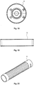
- the expansion chamber 4 and the reflection chamber 5 result in connection of the damping element 3 with a in the FIGS. 19 and 20 individually shown cladding tube 6, which surrounds the damping element 3.
- the damping element 3 and the cladding tube 6 may for example consist of aluminum.
- FIGS. 11 to 13 it can be seen that at least one helical wall 7 is arranged within the reflection chamber 5.
- the in the FIGS. 11 to 13 illustrated embodiment is two substantially mutually parallel helical walls 7 and 8.
- the reflection chamber 5 in principle in two sub-chambers or in two sub-chambers.
- this construction enables a simultaneous and homogeneous gas expansion in both directions, resulting in a better cooling of the gas flowing through a central firing channel 9 of the damping element 3, which is produced when the firearm 1 is fired.
- This gas can be through a plurality of holes 10, which are located in the damping element 3, flow from the firing channel 9 into the reflection chamber 5 and into the expansion chamber 4.
- This overflow of the gas from the firing channel 9 into the expansion chamber 4 and / or into the reflection chamber 5 is known per se and will therefore not be described in detail below.
- FIGS. 11, 12 and 13 is further seen that at one end of the at least one helical wall 7, in the present case at the end of the helical walls 7 and 8, a reflection chamber 5 occlusive partition member 11 is arranged.
- respective separating elements 11 are provided at both ends of the helical walls 7 and 8.
- one of the separating elements 11 forms the separation between the reflection chamber 5 and the expansion chamber 4 and the other separating element 11 forms the front, ie the firearm 1 facing away from the damping element 3.
- the two helical walls 7 and 8 are via respective dividers 12 with the separating elements 11 connected.
- a further separating element 13 is provided, which divides the reflection chamber 5 again and thus in a total of four sub-chambers.
- Fig. 15 It can be seen that the bores 10 extending from the firing channel 9 to the expansion chamber 4 are widened in a funnel shape.
- the funnel-shaped enlargement of the holes 10 is preferably provided only in such a region that a weakening of the damping element 3 is prevented.
- the bores 10 which extend from the firing channel 9 into the reflection chamber 5 and into the expansion chamber 4 are arranged spirally around the circumference of the damping element 3, ie. H. They follow the course of the two spiral walls 7 and 8. In the present case, seven holes 10 are arranged over a revolution of the helical wall 7 and 8, that is, by an angle of 360 °.
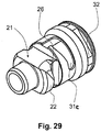
- the engagement member 21 with the projections 22 is in the FIGS. 24 to 29 shown connecting device 19 in the form of an adapter 23 with screw thread assigned to the essay on one end of a firearm barrel or a part thereof.
- the adapter 23 can be connected, for example via an internal thread 24 with an external thread of the firearm 1 and preferably always remains on the firearm 1, so that the muffler 2 can be easily connected to the firearm 1 at any time.
- the connecting device 19 instead of the muffler 2, a so-called and basically known muzzle brake.
- the two bolts 20 extend in an alignment at least approximately perpendicular to a longitudinal axis of the muffler 2 or at least approximately perpendicular to the firing channel 9 Level with distance from each other.
- the engagement member 21 has a width which is smaller than the distance of the two bolts 20, so that the engagement member 21 can be passed through the two bolts 20.
- the connecting device 19 could also have more than the two bolts 20 and more than the two projections 22. However, it should be ensured in such a case that the protrusions 22 having engagement element 21 can still be passed through the bolts 20.
- the two projections 22 have a respective inclined surface 25, which leads to a Verrastnut 26 in which the bolts 20 in their latching with the engagement member 21, ie in the in Fig. 5 position shown, are.
- the latching groove 26 thus forms a repository seat for the respective bolt 20 in its latched position.
- the transition from the inclined surface 25 into the Verrastnut 26 is preferably cured, for example by means of surface hardening to prevent wear.
- a sealing ring 27 is arranged on one of the firearm 1 dressed end of a central bore of the muffler 2, which extends in extension of the firing channel 9 and this ,
- the damping element 3 has a corresponding circumferential groove 27a.
- the adapter 23 In its region facing away from the internal thread 24, the adapter 23 also has a cylindrical mating surface, which engages or bears against a corresponding bore in the damping element 3.
- Another sealing ring 29 is also provided between the damping element 3 and the adapter 23 in a region remote from the firearm 1, as seen from the sealing ring 27, again with a groove 29a in the damping element 3 is introduced to receive the sealing ring 29.
- the two sealing rings 27 and 29 are also in the enlarged view of Fig. 3 to recognize.
- an anti-rotation 31a, 31b and 31c which is a in Fig. 12 having to be recognized threaded hole 31a.
- grub screw 31b are screwed, which engages in the assembly of the muffler 2 on the connecting device 19 designed as an adapter 23 in a guide groove 31c. See also Fig. 24 . 28 and 29 , Due to the presence of the two projections 22 which engage behind the two bolts 20, the muffler 2 could in principle be mounted in two positions rotated by 180 ° relative to one another on the firearm 1 or on the adapter 23.
- the threaded pin described above is screwed into the threaded hole 31 a. Since the adapter 23 has only one guide groove 31c, the muffler 2 can be fixed in this way only in exactly one position on the adapter 23.
- the concentricity of the section of the firing channel 9 extending in the cover 14 relative to that of the firearm 1 can be measured by means of a dial indicator and thus the preferred mounting position of the silencer 2 on the firearm 1 can be determined.
- the adapter 23 has a plurality of flats 32 formed by grooves in the otherwise cylindrical body of the adapter 23 and which serve to bring a tool into engagement with the adapter 23 in order to screw this with a sufficiently high force on the external thread of the firearm 1 and the barrel 111.
Landscapes
- Engineering & Computer Science (AREA)
- General Engineering & Computer Science (AREA)
- Exhaust Silencers (AREA)
Applications Claiming Priority (2)
| Application Number | Priority Date | Filing Date | Title |
|---|---|---|---|
| DE202016001050 | 2016-02-18 | ||
| DE102016113983.1A DE102016113983A1 (de) | 2016-02-18 | 2016-07-28 | Schalldämpfer |
Publications (2)
| Publication Number | Publication Date |
|---|---|
| EP3208567A1 true EP3208567A1 (fr) | 2017-08-23 |
| EP3208567B1 EP3208567B1 (fr) | 2019-04-10 |
Family
ID=58108398
Family Applications (1)
| Application Number | Title | Priority Date | Filing Date |
|---|---|---|---|
| EP17020060.4A Active EP3208567B1 (fr) | 2016-02-18 | 2017-02-20 | Amortisseur de bruit |
Country Status (1)
| Country | Link |
|---|---|
| EP (1) | EP3208567B1 (fr) |
Cited By (3)
| Publication number | Priority date | Publication date | Assignee | Title |
|---|---|---|---|---|
| NO344112B1 (no) * | 2018-04-26 | 2019-09-09 | Svemko As | Hurtigkobling for kobling av lyddemper eller annet tilleggsutstyr til våpen |
| DE102020132017A1 (de) | 2020-12-02 | 2022-06-02 | EP Arms GmbH | Schalldämpfer zur Montage an einem Waffenlauf |
| WO2022194758A1 (fr) * | 2021-03-18 | 2022-09-22 | SFT Produktions GMBH | Silencieux doté d'un frein de bouche intégré pour arme à feu |
Citations (7)
| Publication number | Priority date | Publication date | Assignee | Title |
|---|---|---|---|---|
| DE4410625A1 (de) | 1994-03-26 | 1995-09-28 | Rheinmetall Ind Gmbh | Schalldämpfer für Waffen |
| DE19935929C1 (de) | 1999-07-30 | 2001-02-15 | Heckler & Koch Gmbh | Halterung zur Befestigung eines Schalldämpfers am Lauf einer Handfeuerwaffe |
| DE10001374C1 (de) | 2000-01-14 | 2001-06-21 | Heckler & Koch Gmbh | Halterung zur Befestigung eines Schalldämpfers am Lauf einer Handfeuerwaffe |
| EP1764577A1 (fr) * | 2005-09-15 | 2007-03-21 | Gaston Glock | Silencieux |
| US20070095198A1 (en) * | 2005-10-28 | 2007-05-03 | Delta Tau Data Systems, Inc. | Mounting system for muzzle devices and firearms |
| US20150253098A1 (en) * | 2013-08-16 | 2015-09-10 | Travis Russell | System and method for attaching a sound suppressor to a firearm |
| DE102014119734A1 (de) | 2014-12-30 | 2016-06-30 | Hörmann KG Antriebstechnik | Verfahren zum Betreiben eines Türantriebs, Türantriebssteuerung, Türantrieb und Drehflügeltür |
-
2017
- 2017-02-20 EP EP17020060.4A patent/EP3208567B1/fr active Active
Patent Citations (7)
| Publication number | Priority date | Publication date | Assignee | Title |
|---|---|---|---|---|
| DE4410625A1 (de) | 1994-03-26 | 1995-09-28 | Rheinmetall Ind Gmbh | Schalldämpfer für Waffen |
| DE19935929C1 (de) | 1999-07-30 | 2001-02-15 | Heckler & Koch Gmbh | Halterung zur Befestigung eines Schalldämpfers am Lauf einer Handfeuerwaffe |
| DE10001374C1 (de) | 2000-01-14 | 2001-06-21 | Heckler & Koch Gmbh | Halterung zur Befestigung eines Schalldämpfers am Lauf einer Handfeuerwaffe |
| EP1764577A1 (fr) * | 2005-09-15 | 2007-03-21 | Gaston Glock | Silencieux |
| US20070095198A1 (en) * | 2005-10-28 | 2007-05-03 | Delta Tau Data Systems, Inc. | Mounting system for muzzle devices and firearms |
| US20150253098A1 (en) * | 2013-08-16 | 2015-09-10 | Travis Russell | System and method for attaching a sound suppressor to a firearm |
| DE102014119734A1 (de) | 2014-12-30 | 2016-06-30 | Hörmann KG Antriebstechnik | Verfahren zum Betreiben eines Türantriebs, Türantriebssteuerung, Türantrieb und Drehflügeltür |
Cited By (4)
| Publication number | Priority date | Publication date | Assignee | Title |
|---|---|---|---|---|
| NO344112B1 (no) * | 2018-04-26 | 2019-09-09 | Svemko As | Hurtigkobling for kobling av lyddemper eller annet tilleggsutstyr til våpen |
| DE102020132017A1 (de) | 2020-12-02 | 2022-06-02 | EP Arms GmbH | Schalldämpfer zur Montage an einem Waffenlauf |
| US11644266B2 (en) | 2020-12-02 | 2023-05-09 | EP Arms GmbH | Silencer for mounting on a gun barrel |
| WO2022194758A1 (fr) * | 2021-03-18 | 2022-09-22 | SFT Produktions GMBH | Silencieux doté d'un frein de bouche intégré pour arme à feu |
Also Published As
| Publication number | Publication date |
|---|---|
| EP3208567B1 (fr) | 2019-04-10 |
Similar Documents
| Publication | Publication Date | Title |
|---|---|---|
| DE102007022186A1 (de) | Adapter zum Betreiben einer Lochsäge an einer Antriebsmaschine | |
| WO2017102012A1 (fr) | Dispositif de fixation pour accessoire d'arme | |
| DE102009039669A1 (de) | Handfeuerwaffe | |
| DE2733526C2 (de) | Vorrichtung zum lösbaren Verbinden der Kolbenstange und des Kolbens einer Injektionsspritze | |
| DE102016000437A1 (de) | Einrichtung zum lösbaren Befestigen eines Schalldämpfers und Schalldämpferanordnung | |
| DE102017127750A1 (de) | Drahtgewindeeinsatz | |
| EP3208567B1 (fr) | Amortisseur de bruit | |
| DE102011001160A1 (de) | Verriegelungseinrichtung zum Verriegeln und Entriegeln eines in einer Teigteilkammer eines Teigteilkammerträgers einer Teigteilmaschine aufgenommenen Innenelements | |
| DE1453934A1 (de) | Selbsttaetige Feuerwaffe | |
| EP3699541B1 (fr) | Système de montage d'un silencieux sur un canon d'une arme à feu | |
| DE102014109567A1 (de) | Gasdruckladegewehr | |
| DE102014116420A1 (de) | Sanitärarmatur mit versetzt angeordneter Bedienungselementschwenkachse | |
| EP1888832B1 (fr) | Systeme de blocage pour le transport | |
| DE202007018625U1 (de) | Schneidbrenner mit einem Brennerkopf, der eine auswechselbare Schneiddüse aufnimmt | |
| DE102016113983A1 (de) | Schalldämpfer | |
| DE102010041165A1 (de) | Bohrschraube | |
| EP2363678A2 (fr) | Arme à répétition dotée d'un groupe de fermeture canon-culasse échangeable | |
| WO2008141736A1 (fr) | Dispositif et procédé de fixation d'un frein de bouche sur le tube d'une arme | |
| DE202014103141U1 (de) | Gasdruckladegewehr | |
| DE102007011503A1 (de) | Handfeuerwaffe | |
| DE60203727T2 (de) | Vorrichtung zur befestigung eines gerätes zur brechung der akustischen impedanz eines stiftes | |
| DE202023105245U1 (de) | Kupplungs- oder Bremsvorrichtung | |
| DE102016105776B4 (de) | Befestigungselement für einen Seilhalter und Seilhalter mit Befestigungselement | |
| DE102021128018A1 (de) | Befestigungssystem für Schallwaffenzubehör | |
| DE102023107253A1 (de) | Ventilzungenanordnung für einen Radialkolbenverdichter, Radialkolbenverdichter und Verfahren zur Montage einer Ventilzungenanordnung an einem Radialkolbenverdichter |
Legal Events
| Date | Code | Title | Description |
|---|---|---|---|
| PUAI | Public reference made under article 153(3) epc to a published international application that has entered the european phase |
Free format text: ORIGINAL CODE: 0009012 |
|
| STAA | Information on the status of an ep patent application or granted ep patent |
Free format text: STATUS: THE APPLICATION HAS BEEN PUBLISHED |
|
| AK | Designated contracting states |
Kind code of ref document: A1 Designated state(s): AL AT BE BG CH CY CZ DE DK EE ES FI FR GB GR HR HU IE IS IT LI LT LU LV MC MK MT NL NO PL PT RO RS SE SI SK SM TR |
|
| AX | Request for extension of the european patent |
Extension state: BA ME |
|
| STAA | Information on the status of an ep patent application or granted ep patent |
Free format text: STATUS: REQUEST FOR EXAMINATION WAS MADE |
|
| 17P | Request for examination filed |
Effective date: 20180221 |
|
| RBV | Designated contracting states (corrected) |
Designated state(s): AL AT BE BG CH CY CZ DE DK EE ES FI FR GB GR HR HU IE IS IT LI LT LU LV MC MK MT NL NO PL PT RO RS SE SI SK SM TR |
|
| GRAP | Despatch of communication of intention to grant a patent |
Free format text: ORIGINAL CODE: EPIDOSNIGR1 |
|
| STAA | Information on the status of an ep patent application or granted ep patent |
Free format text: STATUS: GRANT OF PATENT IS INTENDED |
|
| RIC1 | Information provided on ipc code assigned before grant |
Ipc: F41A 21/32 20060101ALN20180830BHEP Ipc: F41A 21/30 20060101AFI20180830BHEP |
|
| INTG | Intention to grant announced |
Effective date: 20180913 |
|
| RIC1 | Information provided on ipc code assigned before grant |
Ipc: F41A 21/32 20060101ALN20180904BHEP Ipc: F41A 21/30 20060101AFI20180904BHEP |
|
| GRAS | Grant fee paid |
Free format text: ORIGINAL CODE: EPIDOSNIGR3 |
|
| GRAA | (expected) grant |
Free format text: ORIGINAL CODE: 0009210 |
|
| STAA | Information on the status of an ep patent application or granted ep patent |
Free format text: STATUS: THE PATENT HAS BEEN GRANTED |
|
| AK | Designated contracting states |
Kind code of ref document: B1 Designated state(s): AL AT BE BG CH CY CZ DE DK EE ES FI FR GB GR HR HU IE IS IT LI LT LU LV MC MK MT NL NO PL PT RO RS SE SI SK SM TR |
|
| REG | Reference to a national code |
Ref country code: GB Ref legal event code: FG4D Free format text: NOT ENGLISH |
|
| REG | Reference to a national code |
Ref country code: CH Ref legal event code: EP Ref country code: AT Ref legal event code: REF Ref document number: 1119273 Country of ref document: AT Kind code of ref document: T Effective date: 20190415 |
|
| REG | Reference to a national code |
Ref country code: IE Ref legal event code: FG4D Free format text: LANGUAGE OF EP DOCUMENT: GERMAN |
|
| REG | Reference to a national code |
Ref country code: DE Ref legal event code: R096 Ref document number: 502017001048 Country of ref document: DE |
|
| REG | Reference to a national code |
Ref country code: NL Ref legal event code: MP Effective date: 20190410 |
|
| REG | Reference to a national code |
Ref country code: LT Ref legal event code: MG4D |
|
| PG25 | Lapsed in a contracting state [announced via postgrant information from national office to epo] |
Ref country code: NL Free format text: LAPSE BECAUSE OF FAILURE TO SUBMIT A TRANSLATION OF THE DESCRIPTION OR TO PAY THE FEE WITHIN THE PRESCRIBED TIME-LIMIT Effective date: 20190410 |
|
| PG25 | Lapsed in a contracting state [announced via postgrant information from national office to epo] |
Ref country code: PT Free format text: LAPSE BECAUSE OF FAILURE TO SUBMIT A TRANSLATION OF THE DESCRIPTION OR TO PAY THE FEE WITHIN THE PRESCRIBED TIME-LIMIT Effective date: 20190910 Ref country code: LT Free format text: LAPSE BECAUSE OF FAILURE TO SUBMIT A TRANSLATION OF THE DESCRIPTION OR TO PAY THE FEE WITHIN THE PRESCRIBED TIME-LIMIT Effective date: 20190410 Ref country code: FI Free format text: LAPSE BECAUSE OF FAILURE TO SUBMIT A TRANSLATION OF THE DESCRIPTION OR TO PAY THE FEE WITHIN THE PRESCRIBED TIME-LIMIT Effective date: 20190410 Ref country code: NO Free format text: LAPSE BECAUSE OF FAILURE TO SUBMIT A TRANSLATION OF THE DESCRIPTION OR TO PAY THE FEE WITHIN THE PRESCRIBED TIME-LIMIT Effective date: 20190710 Ref country code: AL Free format text: LAPSE BECAUSE OF FAILURE TO SUBMIT A TRANSLATION OF THE DESCRIPTION OR TO PAY THE FEE WITHIN THE PRESCRIBED TIME-LIMIT Effective date: 20190410 Ref country code: SE Free format text: LAPSE BECAUSE OF FAILURE TO SUBMIT A TRANSLATION OF THE DESCRIPTION OR TO PAY THE FEE WITHIN THE PRESCRIBED TIME-LIMIT Effective date: 20190410 Ref country code: HR Free format text: LAPSE BECAUSE OF FAILURE TO SUBMIT A TRANSLATION OF THE DESCRIPTION OR TO PAY THE FEE WITHIN THE PRESCRIBED TIME-LIMIT Effective date: 20190410 |
|
| PG25 | Lapsed in a contracting state [announced via postgrant information from national office to epo] |
Ref country code: LV Free format text: LAPSE BECAUSE OF FAILURE TO SUBMIT A TRANSLATION OF THE DESCRIPTION OR TO PAY THE FEE WITHIN THE PRESCRIBED TIME-LIMIT Effective date: 20190410 Ref country code: RS Free format text: LAPSE BECAUSE OF FAILURE TO SUBMIT A TRANSLATION OF THE DESCRIPTION OR TO PAY THE FEE WITHIN THE PRESCRIBED TIME-LIMIT Effective date: 20190410 Ref country code: PL Free format text: LAPSE BECAUSE OF FAILURE TO SUBMIT A TRANSLATION OF THE DESCRIPTION OR TO PAY THE FEE WITHIN THE PRESCRIBED TIME-LIMIT Effective date: 20190410 Ref country code: GR Free format text: LAPSE BECAUSE OF FAILURE TO SUBMIT A TRANSLATION OF THE DESCRIPTION OR TO PAY THE FEE WITHIN THE PRESCRIBED TIME-LIMIT Effective date: 20190711 Ref country code: BG Free format text: LAPSE BECAUSE OF FAILURE TO SUBMIT A TRANSLATION OF THE DESCRIPTION OR TO PAY THE FEE WITHIN THE PRESCRIBED TIME-LIMIT Effective date: 20190710 |
|
| PG25 | Lapsed in a contracting state [announced via postgrant information from national office to epo] |
Ref country code: IS Free format text: LAPSE BECAUSE OF FAILURE TO SUBMIT A TRANSLATION OF THE DESCRIPTION OR TO PAY THE FEE WITHIN THE PRESCRIBED TIME-LIMIT Effective date: 20190810 |
|
| REG | Reference to a national code |
Ref country code: DE Ref legal event code: R097 Ref document number: 502017001048 Country of ref document: DE |
|
| PG25 | Lapsed in a contracting state [announced via postgrant information from national office to epo] |
Ref country code: CZ Free format text: LAPSE BECAUSE OF FAILURE TO SUBMIT A TRANSLATION OF THE DESCRIPTION OR TO PAY THE FEE WITHIN THE PRESCRIBED TIME-LIMIT Effective date: 20190410 Ref country code: EE Free format text: LAPSE BECAUSE OF FAILURE TO SUBMIT A TRANSLATION OF THE DESCRIPTION OR TO PAY THE FEE WITHIN THE PRESCRIBED TIME-LIMIT Effective date: 20190410 Ref country code: RO Free format text: LAPSE BECAUSE OF FAILURE TO SUBMIT A TRANSLATION OF THE DESCRIPTION OR TO PAY THE FEE WITHIN THE PRESCRIBED TIME-LIMIT Effective date: 20190410 Ref country code: DK Free format text: LAPSE BECAUSE OF FAILURE TO SUBMIT A TRANSLATION OF THE DESCRIPTION OR TO PAY THE FEE WITHIN THE PRESCRIBED TIME-LIMIT Effective date: 20190410 Ref country code: SK Free format text: LAPSE BECAUSE OF FAILURE TO SUBMIT A TRANSLATION OF THE DESCRIPTION OR TO PAY THE FEE WITHIN THE PRESCRIBED TIME-LIMIT Effective date: 20190410 |
|
| PLBE | No opposition filed within time limit |
Free format text: ORIGINAL CODE: 0009261 |
|
| STAA | Information on the status of an ep patent application or granted ep patent |
Free format text: STATUS: NO OPPOSITION FILED WITHIN TIME LIMIT |
|
| PG25 | Lapsed in a contracting state [announced via postgrant information from national office to epo] |
Ref country code: SM Free format text: LAPSE BECAUSE OF FAILURE TO SUBMIT A TRANSLATION OF THE DESCRIPTION OR TO PAY THE FEE WITHIN THE PRESCRIBED TIME-LIMIT Effective date: 20190410 Ref country code: IT Free format text: LAPSE BECAUSE OF FAILURE TO SUBMIT A TRANSLATION OF THE DESCRIPTION OR TO PAY THE FEE WITHIN THE PRESCRIBED TIME-LIMIT Effective date: 20190410 |
|
| 26N | No opposition filed |
Effective date: 20200113 |
|
| PG25 | Lapsed in a contracting state [announced via postgrant information from national office to epo] |
Ref country code: TR Free format text: LAPSE BECAUSE OF FAILURE TO SUBMIT A TRANSLATION OF THE DESCRIPTION OR TO PAY THE FEE WITHIN THE PRESCRIBED TIME-LIMIT Effective date: 20190410 |
|
| PG25 | Lapsed in a contracting state [announced via postgrant information from national office to epo] |
Ref country code: SI Free format text: LAPSE BECAUSE OF FAILURE TO SUBMIT A TRANSLATION OF THE DESCRIPTION OR TO PAY THE FEE WITHIN THE PRESCRIBED TIME-LIMIT Effective date: 20190410 |
|
| REG | Reference to a national code |
Ref country code: CH Ref legal event code: PL |
|
| REG | Reference to a national code |
Ref country code: BE Ref legal event code: MM Effective date: 20200229 |
|
| PG25 | Lapsed in a contracting state [announced via postgrant information from national office to epo] |
Ref country code: LU Free format text: LAPSE BECAUSE OF NON-PAYMENT OF DUE FEES Effective date: 20200220 Ref country code: MC Free format text: LAPSE BECAUSE OF FAILURE TO SUBMIT A TRANSLATION OF THE DESCRIPTION OR TO PAY THE FEE WITHIN THE PRESCRIBED TIME-LIMIT Effective date: 20190410 Ref country code: ES Free format text: LAPSE BECAUSE OF FAILURE TO SUBMIT A TRANSLATION OF THE DESCRIPTION OR TO PAY THE FEE WITHIN THE PRESCRIBED TIME-LIMIT Effective date: 20190410 |
|
| PG25 | Lapsed in a contracting state [announced via postgrant information from national office to epo] |
Ref country code: LI Free format text: LAPSE BECAUSE OF NON-PAYMENT OF DUE FEES Effective date: 20200229 Ref country code: CH Free format text: LAPSE BECAUSE OF NON-PAYMENT OF DUE FEES Effective date: 20200229 |
|
| PG25 | Lapsed in a contracting state [announced via postgrant information from national office to epo] |
Ref country code: IE Free format text: LAPSE BECAUSE OF NON-PAYMENT OF DUE FEES Effective date: 20200220 Ref country code: FR Free format text: LAPSE BECAUSE OF NON-PAYMENT OF DUE FEES Effective date: 20200229 |
|
| PG25 | Lapsed in a contracting state [announced via postgrant information from national office to epo] |
Ref country code: BE Free format text: LAPSE BECAUSE OF NON-PAYMENT OF DUE FEES Effective date: 20200229 |
|
| GBPC | Gb: european patent ceased through non-payment of renewal fee |
Effective date: 20210220 |
|
| PG25 | Lapsed in a contracting state [announced via postgrant information from national office to epo] |
Ref country code: GB Free format text: LAPSE BECAUSE OF NON-PAYMENT OF DUE FEES Effective date: 20210220 |
|
| PG25 | Lapsed in a contracting state [announced via postgrant information from national office to epo] |
Ref country code: MT Free format text: LAPSE BECAUSE OF FAILURE TO SUBMIT A TRANSLATION OF THE DESCRIPTION OR TO PAY THE FEE WITHIN THE PRESCRIBED TIME-LIMIT Effective date: 20190410 Ref country code: CY Free format text: LAPSE BECAUSE OF FAILURE TO SUBMIT A TRANSLATION OF THE DESCRIPTION OR TO PAY THE FEE WITHIN THE PRESCRIBED TIME-LIMIT Effective date: 20190410 |
|
| PG25 | Lapsed in a contracting state [announced via postgrant information from national office to epo] |
Ref country code: MK Free format text: LAPSE BECAUSE OF FAILURE TO SUBMIT A TRANSLATION OF THE DESCRIPTION OR TO PAY THE FEE WITHIN THE PRESCRIBED TIME-LIMIT Effective date: 20190410 |
|
| PGFP | Annual fee paid to national office [announced via postgrant information from national office to epo] |
Ref country code: AT Payment date: 20230215 Year of fee payment: 7 |
|
| PGFP | Annual fee paid to national office [announced via postgrant information from national office to epo] |
Ref country code: DE Payment date: 20221219 Year of fee payment: 7 |
|
| REG | Reference to a national code |
Ref country code: DE Ref legal event code: R119 Ref document number: 502017001048 Country of ref document: DE |
|
| REG | Reference to a national code |
Ref country code: AT Ref legal event code: MM01 Ref document number: 1119273 Country of ref document: AT Kind code of ref document: T Effective date: 20240220 |
|
| PG25 | Lapsed in a contracting state [announced via postgrant information from national office to epo] |
Ref country code: AT Free format text: LAPSE BECAUSE OF NON-PAYMENT OF DUE FEES Effective date: 20240220 |
|
| PG25 | Lapsed in a contracting state [announced via postgrant information from national office to epo] |
Ref country code: AT Free format text: LAPSE BECAUSE OF NON-PAYMENT OF DUE FEES Effective date: 20240220 |
|
| PG25 | Lapsed in a contracting state [announced via postgrant information from national office to epo] |
Ref country code: DE Free format text: LAPSE BECAUSE OF NON-PAYMENT OF DUE FEES Effective date: 20240903 |
|
| PG25 | Lapsed in a contracting state [announced via postgrant information from national office to epo] |
Ref country code: DE Free format text: LAPSE BECAUSE OF NON-PAYMENT OF DUE FEES Effective date: 20240903 |