EP3208577B1 - Procédé et appareil de détection du niveau de liquide dans un réservoir de liquide - Google Patents
Procédé et appareil de détection du niveau de liquide dans un réservoir de liquide Download PDFInfo
- Publication number
- EP3208577B1 EP3208577B1 EP16156174.1A EP16156174A EP3208577B1 EP 3208577 B1 EP3208577 B1 EP 3208577B1 EP 16156174 A EP16156174 A EP 16156174A EP 3208577 B1 EP3208577 B1 EP 3208577B1
- Authority
- EP
- European Patent Office
- Prior art keywords
- volume
- valve member
- reservoir
- signal
- port
- Prior art date
- Legal status (The legal status is an assumption and is not a legal conclusion. Google has not performed a legal analysis and makes no representation as to the accuracy of the status listed.)
- Active
Links
Images


Classifications
-
- G—PHYSICS
- G01—MEASURING; TESTING
- G01F—MEASURING VOLUME, VOLUME FLOW, MASS FLOW OR LIQUID LEVEL; METERING BY VOLUME
- G01F22/00—Methods or apparatus for measuring volume of fluids or fluent solid material, not otherwise provided for
- G01F22/02—Methods or apparatus for measuring volume of fluids or fluent solid material, not otherwise provided for involving measurement of pressure
-
- G—PHYSICS
- G01—MEASURING; TESTING
- G01F—MEASURING VOLUME, VOLUME FLOW, MASS FLOW OR LIQUID LEVEL; METERING BY VOLUME
- G01F23/00—Indicating or measuring liquid level or level of fluent solid material, e.g. indicating in terms of volume or indicating by means of an alarm
- G01F23/14—Indicating or measuring liquid level or level of fluent solid material, e.g. indicating in terms of volume or indicating by means of an alarm by measurement of pressure
- G01F23/18—Indicating, recording or alarm devices actuated electrically
-
- G—PHYSICS
- G01—MEASURING; TESTING
- G01F—MEASURING VOLUME, VOLUME FLOW, MASS FLOW OR LIQUID LEVEL; METERING BY VOLUME
- G01F23/00—Indicating or measuring liquid level or level of fluent solid material, e.g. indicating in terms of volume or indicating by means of an alarm
- G01F23/80—Arrangements for signal processing
-
- G—PHYSICS
- G01—MEASURING; TESTING
- G01F—MEASURING VOLUME, VOLUME FLOW, MASS FLOW OR LIQUID LEVEL; METERING BY VOLUME
- G01F17/00—Methods or apparatus for determining the capacity of containers or cavities, or the volume of solid bodies
-
- G—PHYSICS
- G01—MEASURING; TESTING
- G01F—MEASURING VOLUME, VOLUME FLOW, MASS FLOW OR LIQUID LEVEL; METERING BY VOLUME
- G01F23/00—Indicating or measuring liquid level or level of fluent solid material, e.g. indicating in terms of volume or indicating by means of an alarm
- G01F23/14—Indicating or measuring liquid level or level of fluent solid material, e.g. indicating in terms of volume or indicating by means of an alarm by measurement of pressure
Definitions
- the invention relates to a method for determining a gas pressure inside a reservoir in response to a change of the reservoir volume, thereby enabling to determine the gas volume inside the reservoir. If the reservoir volume is known a priori, the volume of an incompressible liquid inside the reservoir can be calculated.
- Detection of fluid levels in reservoirs has a multitude of applications. It is particularly critical in safely operating combustion engines drawing fuel from the reservoir. Numerous variants for detecting fluid levels have been reported, e.g. measuring the float level of a float gauge, capacitive fluid level detection (e.g EP 2759 812 , DE 102004047413 A1 ), microwave fluid level detection ( US 8,763,453 B2 , US 7,843,199 B2 ), ultrasonic level detection based on propagation time measurements (e.g. US 7, 010,974 B2 ). All these methods are sensitive to changes of the orientation of the reservoir in space and or sloshing of the liquid inside the reservoir, which is often due to acceleration of the reservoir.
- capacitive fluid level detection e.g EP 2759 812 , DE 102004047413 A1
- microwave fluid level detection US 8,763,453 B2 , US 7,843,199 B2
- ultrasonic level detection based on propagation time measurements e.g. US 7, 010,
- DE 29 53 903 suggests an indirect measurement of the fill level of a fuel reservoir by changing the fuel reservoir's volume and to measure the resulting change of the pressure inside the reservoir. Similar approaches have been suggested in US 7,347,089 B1 , DE 35 40 768 C1 , DE 43 39 933 A1 , WO8302001 A1 or DE 897 331 . This approach is based on the fact, that the fuel in the reservoir is essentially an incompressible liquid (herein briefly 'liquid') and that the 'empty' space is occupied by a compressible gas (herein briefly 'gas'), usually air, having the volume V g .
- a compressible gas herein briefly 'gas'
- the problem to be solved by the invention is to accurately determine a pressure change in response to change of the reservoir's volume, thereby enhancing fill level detection of a liquid reservoir, wherein the liquid is exchanged with a gas when drawing or refilling the liquid.
- the invention provides a possibility to preferably periodically alter the volume of the reservoir in particular by using a modified valve.
- the periodic alteration of the volume provides a periodic response of the pressure.
- the pressure response signal can be distinguished from noise signals, i.e. the pressure response signal can be retrieved even if it is only of the order of magnitude of the noise and so to speak 'hides in the noise'.
- altering of the volume does not necessarily need to be periodically, but this embodiment is particular instructive.
- the apparatus for altering the volume of a liquid reservoir comprises at least a valve.
- the valve has at least a first port being in fluid communication with the liquid reservoir and a second port.
- the second port can be connected e.g. with another reservoir, a vent opening, a combustion engine's manifold or the like.
- the valve has a conduit for enabling a liquid communication between the first and the second port.
- the liquid communication can be controlled, i.e. the valve can be opened or closed by moving, e.g. displacing or rotating a valve member.
- the valve member has an open position in which the first port and the second port are in fluid communication via said conduit.
- the valve member further has a first closed position, in which the fluid communication between the first port and the second port is blocked by the valve member.
- the valve member is moveable into at least a second closed positon, in which the fluid communication between the first port and the second port remains closed, i.e. blocked, by the valve member.
- Moving the valve member between the first and second closed positions changes the volume of a chamber being in fluid communication with the first port and thus with the reservoir.
- the valve member restricts a chamber being in fluid communication with the reservoir via the first port. Moving of the valve member thus changes the chamber volume and thus the effective volume of the reservoir.
- the first port is preferably in fluid communication with a chamber, into which the valve member protrudes, when the valve member protrudes when it is moved from its first to its second closed position.
- valve member can be operated by a drive, i.e. an actuator, e.g. a solenoid drive, a rotary drive or the like.
- a drive i.e. an actuator, e.g. a solenoid drive, a rotary drive or the like.
- the valve has a valve member being movably supported, e.g. in a valve housing, thereby enabling its movement for opening or closing of the valve has at least two closed positions.
- the valve member By iteratively moving the valve member from one of these two closed positions into the other closed position, the volume of the chamber and thus the reservoir can be iteratively altered. Iteratively moving the valve member between these two closed positions thus enables to e.g. periodically alter the volume V g ( t ) and thus the pressure p(t) of the compressible gas inside the reservoir as function of time t.
- the pressure sensor can be integrated in the apparatus, thereby reducing manufacturing cost as well as installation costs.
- the apparatus may comprise a sensor, said sensor measuring a signal being representative for the force F required the move the valve member against the pressure in the reservoir from the first to the second closed position and/or from the second to the first closed position.
- the signal being representative for the force F is the voltage and/or the current feed to a drive for moving the valve member between the first and second closed position.
- the reservoir is a fuel tank of a combustion engine.
- the valve can be e.g. a Fuel Tank Isolation Valve (commonly FTIV) for controlling a fluid communication between the reservoir and the environment (usually via a filter, e.g. an activated charcoal filter, like an activated carbon canister) or a Fuel Tank Vent valve for controlling a fluid communication between the reservoir and an engine air intake, e.g. the engine's intake manifold.
- Valves like these are already standard in modern combustion engine powered apparatuses, like cars, piston aircraft, motorcycles, power stations. Thus, by simply replacing the prior art valves, the fill level of the fuel reservoir can be determined easily.
- the reservoir is a reductant reservoir for providing a reductant to an exhaust gas for denitrification of the exhaust gas.
- Typical reductants are anhydrous ammonia, aqueous ammonia or an aqueous urea solution as required for selective catalytic reduction of nitrogen oxides.
- Such liquids are commonly referred to e.g. as 'AdBlue ® ' (Europe) or Diesel Exhaust Fluid, briefly DEF (USA).
- the reservoir may be a fuel tank and the valve may be used as Fuel Tank Isolation Valve for controlling a fluid communication between the reservoir and the environment, as Fuel Tank Vent valve for controlling a fluid communication between the reservoir and an engine air intake and/or a canister being in fluid communication with the environment, as Fuel Tank Separation Valve for isolating the reservoir from the engine, a canister and environment during canister purging, as Atmospheric Isolation Valve for isolating a canister and/or the reservoir from the atmosphere to prevent gas emissions after shutoff or as Fuel Tank Shutoff Valve for controlling fluid communication between a combustion engine and the reservoir.
- Fuel Tank Isolation Valve for controlling a fluid communication between the reservoir and the environment
- Fuel Tank Vent valve for controlling a fluid communication between the reservoir and an engine air intake and/or a canister being in fluid communication with the environment
- Fuel Tank Separation Valve for isolating the reservoir from the engine, a canister and environment during canister purging
- the conduit may comprise a valve seat and the valve member closes the valve seat in its first and second closed positions and opens the valve seat when moved in its open position.
- An elastic gasket may seal the valve seat in the closed positions.
- the elastic gasket is positioned between a gasket facing contact surface of the valve member and the valve seat.
- the valve member presses the gasket against the valve seat.
- the elastic gasket By displacing the valve member from the first closed position into the second closed positon the elastic gasket is compressed. If the valve member is positioned between the first port and the valve seat, compressing the gasket augments the volume of the chamber being in fluid communication with the first port and thus reduces the pressure in the chamber and thus the gas volume.
- the gasket When moving the valve member from the second closed position to the first closed position, the gasket expands and thus the volume of the chamber is reduced. Accordingly, the pressure in the chamber and thus as well in the reservoir is augmented. If the valve member is positioned at the other side, i.e. between the second port and the valve seat, compressing the gasket results in a reduced volume of the chamber being in fluid communication with the first port and thus the reservoir and thus essentially of the reservoir. Accordingly, the pressure in the reservoir is augmented. Moving the valve member back in its first closed position, the gasket expands; accordingly the gas volume is augmented and the pressure reduced. In this example, we assumed for simplicity only that the valve member does not protrude through the valve seat, but of course it can. In this case one would have to consider the position of a gasket facing contact surface for contacting the gasket and not the complete valve member.
- the valve member comprises at least a section of the conduit.
- the conduit has at least a first opening being positioned in front of the first port and a second opening being positioned in front of a second port if the valve member is in its open position, to thereby provide said fluid communication.
- the conduit openings do not need to be directly in front of the respective ports, but the ports should be in liquid communication with openings of the conduit and thus with each other.
- the first port is preferably in fluid communication with a chamber, into which the valve member protrudes, when the valve member is moved from its first to its second closed position.
- the boundary of the chamber closes at least one of said first and/or second openings of the conduit, when moving the valve member from its open position into its first and/or second closed positions.
- the valve member could be or resemble a piston, being movably supported in a cylinder.
- the conduit may extend e.g. perpendicular (but of course as well oblique) through the piston.
- the first and second ports can be provided by through holes in the cylinder wall. The through holes are positioned to be connected by the conduit, if the valve member is in its open position. If the valve member is advanced or retracted, i.e. axially moved in the cylinder, and/or rotated the through holes are closed by the piston.
- the cylinder provides a chamber, being enclosed by the piston.
- Said chamber is connected, e.g. by a tube or any other kind of conduit, to the first port.
- advancing (or retracting) the valve member briefly any axial movement alters the volume of the chamber and thus of the gas.
- the pressure response can be detected by any pressure sensing means and thus the gas volume V g can be determined.
- the volume of the chamber can be augmented or reduced.
- the volume may be oscillated, by oscillating the valve member. The corresponding pressure thus oscillates accordingly.
- the valve comprises a chamber being in fluid communication with the first port.
- the valve member is rotably supported and comprises a conduit for connecting said first and second ports. By rotating the valve member, a ring segment is inserted into said chamber, thereby closing the second port. Further rotation of the valve member reduces the volume of the chamber and thus enables to compress the gas in the chamber and thus in the reservoir.
- the pressure response can be detected as explained above.
- This signal is subsequently referred to as initial signal S(t) or reference signal S ( t ).
- the initial signal S(t) may be periodic but is not necessarily periodic, but is not constant during a measurement.
- the method for determining a pressure response p(t) of a gas being confined in a reservoir comprises repetitively reducing and augmenting the gas volume V g ( t ) as function of time.
- a pressure signal p ( t ) being representative for the pressure inside the reservoir is measured as function of time t.
- the pressure signal p ( t ) may be the signal provided by a pressure sensor, e.g. after an optional amplification.
- This pressure signal p ( t ) is demodulated, e.g. using the initial signal S ( t ) as reference signal and thereby a demodulated pressure signal p d ( t ) is obtained.
- a previously detected pressure signal p ( t - ⁇ ) may be used for demodulation the pressure signal as well.
- ⁇ denotes a time shift.
- the demodulated signal can be subjected to a low pass and/or a band pass filter, thereby eliminating remaining noise.
- the such obtained pressure signal p d ( t ) can be used to determine ⁇ p / ⁇ V and thus V g .
- the pressure amplitudes can be significantly smaller compared to prior art techniques.
- the above explained valve is sufficient, whereas according to the prior art much bigger volume modulations have been necessary (and of course could still be used, provided the volume is altered as explained above).
- the reservoir volume is preferably in fluid communication with the first port of the valve explained above. Repetitively altering the volume according to the initial signal S ( t ) can be obtained by altering the position of the valve member between at least two of said closed positions.
- the initial signal S ( t ) is a periodic function.
- S ( t ) V 0 ⁇ sin( ⁇ ( t + ⁇ t )), wherein ⁇ denotes an angular frequency, and ⁇ t a time shift.
- ⁇ i , ⁇ i , ⁇ i and ⁇ t i are constants.
- the pressure signal p(t) is amplified prior to its demodulation to thereby simplify processing of the pressure signal p(t).
- the step of demodulation may preferably comprise multiplying the initial signal S(t) with the pressure signal p ( t ), thereby obtaining a demodulated pressure signal.
- Multiplication can be performed digital, i.e. numerically or by an analog mixer.
- the initial signal S ( t ) may be a square signal and demodulation may comprise synchronous amplification of the pressure signal p ( t ) and subsequent integration, thereby essentially eliminating the noise from the signal.
- the estimate for ⁇ p / ⁇ V g can be obtained by simply calculating ⁇ p ⁇ V g ⁇ p d , 1 ⁇ p d , 2 ⁇ V 1 ⁇ ⁇ V 2 , wherein p d ,1 , p d ,2 are the demodulated pressure signals corresponding to ⁇ V 1 and ⁇ V 2 , respectively.
- the angular frequency of the reference signal S(t) is varied. Observing the frequency dependency of the demodulated pressure signal enables to determine the resonance frequency of the volume modulation, i.e. the frequency where the absolute value of the pressure response shows a maximum. This resonance frequency enables to determine the gas volume inside the reservoir as well, e.g. using a look-up table.
- valve member can and in practice will be controlled electrically, e.g. by a (micro) controller operating a drive being operationally connected with the valve member to move it according to the controller's commands.
- a controller operating a drive being operationally connected with the valve member to move it according to the controller's commands.
- pressures and forces are vectors, but for simplicity they have been treated like scalars.
- the reservoir should be closed when altering the volume to measure the response of the pressure. At least, the leakage should be small compared to the change in volume, or in other words the mass of the gas and the liquid in the reservoir should be kept at least almost constant during a measurement.
- the method does not only enable to determine the fill level of a reservoir, but as well to determine the volume of an 'empty' enclosed reservoir, by simply connecting the first port to the reservoir and operating the apparatus as set out above. 'Empty' means the there is only a compressible fluid inside the reservoir. Connecting means here to enable a fluid communication between the reservoir and the first port.
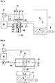
- Figure 1 shows a valve 10 with a valve housing 12 having a first port 21 and a second port 22. At least one of the ports can be connected to a reservoir 5. Subsequently we assume that the first port 21 is connected to the reservoir 5 as indicated by a dotted line 5. The reservoir 5 is not drawn to scale, in practice its volume V r is much larger than the volume enclosed by the valve. An incompressible liquid 7 may occupy a volume V l inside the reservoir 5. The remaining volume V g is filled with a compressible gas 6. If the valve 10 is open, as shown in figure 1a , the reservoir 5 is in fluid communication with the second port 22. The reservoir 5 may have additional openings as indicated by a second valve 8.
- the valve 10 has a valve seat 20 with an opening 24 providing a conduit having a longitudinal axis 25.
- a valve member 30 is movably supported inside the housing, enabling a movement along or at least essentially parallel to the longitudinal axis 25.
- the valve member 30 has a valve seat facing side 32 supporting an elastic gasket 35.
- a translation, i.e. a movement of the valve member 30 enables to bring the gasket 35 in contact with the valve seat 20, thereby closing the opening 24.
- the valve 10 is thus closed and the valve member 30 is now in a first closed position, which is depicted in Fig. 1b .
- valve member 30 pushes the gasket with a first force f 1 against the valve seat 20, to ensure a sealing contact between the gasket 35 and the valve seat 20 as well as between the valve member 30 and the gasket 35.
- the force for pressing the gasket 35 against valve seat 20 can be augmented to a force f 2 until the elastic gasket is deformed as depicted in figure 1c .
- the valve member 30 is in a second closed position. Due to the corresponding movement, i.e. the stroke of the valve member, the gas volume V g is slightly increased, e.g. by a few milliliters. Accordingly, a slight pressure drop can be measured inside the reservoir 5, e.g.
- a pressure sensor 51 being coupled to a controller 50 (for a more detailed example, see figure 5 ).
- a controller 50 for a more detailed example, see figure 5 .
- the valve member 30 can be actuated by a linear drive as indicated in figure 1a to figure 1c .
- the linear drive has a drive housing 40 supporting a spring 41 being coupled to the valve member 30.
- the spring 41 can be a pull-spring as indicated or as well a push spring. In the latter case is should be repositioned accordingly.
- at least one coil 42, 43 (depicted are two coils, a first coil 42 and a second coil 43) is attached to the drive housing.
- the valve member 30 comprises a plunger of a dia- or ferromagnetic material as indicted by reference numeral 44. By applying a current I 1 to at least one of the coils 42, 43 the valve member can be moved against the spring force into its first closed position indicated in figure 1b .
- the force exerted by the valve member 30 to the gasket 35 can be increased to the higher value f 2 and thus the valve member translates into its second closed position (as can be seen in figure 1c ).
- the current through the coils is preferably controlled by the controller 50 as indicated by corresponding lines. Reducing the current back to I 1 (and/or switching the second coil off, respectively) enables to reduce the force back to f 1 , i.e. the spring and the elastic gasket 35 move the valve member 30 back into its first closed position (see figure 1b ). Switching the coils 42, 43 off completely, results in opening the valve 10 (see figure 1a ).
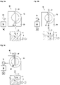
- FIGS 2a to 2c show a further embodiment of an apparatus according to the invention:
- a valve 10 has a valve housing 12 having a first port 21 and a second port 22. At least one of the ports 21, 22 can be connected to a reservoir 5. Subsequently we assume that the first port 21 is connected to the reservoir 5 as indicated by a dotted line.
- the reservoir 5 is not drawn to scale, in practice its volume V r is much larger than the volume enclosed by the valve.
- An incompressible liquid 7 may occupy a volume V l inside the reservoir 5. The remaining volume V g is filled with a compressible gas 6. If the valve 10 is open, as shown in figure 1a , the reservoir 5 is in fluid communication with the second port 22 via a conduit 31. Again, the reservoir 5 may have additional openings as indicated by a second valve 8.
- the valve member 30 has a conduit 31. In the position as shown in figure 2a the conduit 31 connects the first and the second ports 21, 22, or in other words it provides a liquid communication between the first and second ports 21, 22. By moving the valve member 30 forth or back in the housing, the liquid communication can be interrupted as shown in figure 2b and figure 2a .
- the valve member 30 is mechanically coupled to a drive M for pushing or pulling, i.e. moving the valve member as required.
- a controller 50 controls the e.g. linear drive M and thus the movement of the valve member 30.
- the valve housing 12 has a chamber 23 being in fluid communication with the first port 21.
- the volume of the chamber 23 and thus of the first port 21 can be reduced as shown in figure 2b and figure 2c .
- reduction leads to an augmentation of the gas pressure pressure p inside the chamber 23, the first port 21 and the reservoir 5.
- This change in pressure can be detected using a pressure sensor 51 being connected to a controller 50 as already explained with respect to figure 1a to figure 1c .
- the valve in figure 3a to figure 3c has like the valves in figure 1a to figure 2c a valve housing 12 herein with a first port 21 and a second port 22.
- the first port 21 is configured to be connected to a reservoir 5.
- the first port 21 and the second port 22 can be connected, or in other words set in fluid communication by positioning a conduit 31 of a ring segment like valve member 30 in between of the ports 21, 22 as shown in figure 3a .
- volume V g can be varied depending on the (angular) position of the valve member 30, volume V g can be varied.
- the pressure p ( t ) can be detected using a pressure sensor 51 and the corresponding pressure signal p ( t ) can be evaluated by a controller 50.
- the controller may control a drive M for moving the valve member in addition.
- the term 'port' does not only refer to an opening in an enclosure of some space enabling a fluid communication with e.g. between the space and the reservoir or the environment, but as well denotes the enclosed space or so to speak a conduit enabling the fluid communication, e.g. between a chamber inside the valve housing and the reservoir.
- the reference signal is not necessarily periodic, but preferably.
- the pressure p(t) is measured using a pressure sensor providing a first pressure signal p 1 ( t ).
- the pressure sensor may provide a voltage being proportional to the pressure. This voltage signal can be amplified and/or filtered and/or provided to an analog digital converter as required.
- the pressure signal p 1 ( t ) is demodulated using the reference signal S ( t - ⁇ ) in step 130.
- Demodulation can be obtained for example using a mixer or numerically.
- Demodulation provides a demodulated pressure signal p d 1 ( t ) with a significantly enhanced signal to noise ratio.
- the delay-offset ⁇ d is a parameter showing that the measured signal has a phase offset due to electronical and physical delays.
- the corresponding pressure signal p 2 ( t ) can as well be demodulated (Step 130') but of course the second reference signal S 2 ( t ) has to be used to obtain p d ,2 .
- the corresponding pressure signal p(t) is again measured (Step 120") but demodulated twice, once using the first reference signal S 1 ( t ) (Step 130a) and once using the second reference signal S 2 ( t ) (Step 130b).
- demodulation takes place using only the first or second reference signal S 1( t ) ,S 2 ( t ), respectively, to thereby obtain the respective first and second demodulated pressure signals p d, 1 ,p d, 2 .
- an estimate for ⁇ p / ⁇ V g can be obtained as p d , 1 ⁇ p d , 2 ⁇ V 1 ⁇ ⁇ V 2 , i.e. ⁇ p ⁇ V g ⁇ p d , 1 ⁇ p d , 2 ⁇ V 1 ⁇ ⁇ V 2 .
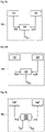
- the circuit comprises a controller 50 configured for digital signal processing.
- the controller may thus comprise a microprocessor or a number of interacting microprocessors.
- the controller 50 comprises a signal generator 55 configured to provide at least a first reference signal S(t) to a driver 56.
- the driver 56 drives and thus controls the movement of a valve member 30 of the valve 10.
- the valve 10 can be e.g. one of the valves as depicted in figures 1 - 3 .
- the valve 10 comprises a movable valve member 30 with an open position in which the first port 21 and the second port 22 are in fluid communication via a conduit.
- the valve member 30 is movable into a first closed position, in which the fluid communication between the first port 21 and the second port 22 is blocked by the valve member 30 (cf. e.g. figures 1b , 2b and 3b ).
- the valve member is movable into at least a second closed positon, in which the fluid communication between the first port 21 and the second port 22 is as well blocked and in which the volume of a chamber being in liquid communication with the first port 21 is altered when moving the valve member 30 from the first closed position to the second closed position and/or from the second to the first closed position.
- the movement of the valve member 30 enables to changes the volume V r of a reservoir 5 being connected to the first port of the valve 10.
- the volume V r of the reservoir remains constant, but as the first port 21 of the valve 10 is connected to the reservoir volume the movement of the valve member has the same effect, i.e. the pressure inside the reservoir changes accordingly.
- This change in pressure is detected by a pressure sensor 51 being in fluid communication with the reservoir 5.
- the corresponding pressure signal p(t) is amplified by an amplifier 52 and optionally filtered, e.g. by a low pass filter 53 to avoid aliasing effects when subsequently digitizing the signal in a digital to analog converter 54 (AD-converter).
- the digitized pressure signal can be processed by the controller 50.
- the AD-converter 54 and as well the signal generator 55 are included in the controller 50, but they do not need to be integrated into a single chip or on a single PCB, but may be separate units.
- valve 10 A typical application of a valve 10 is depicted in figure 6 .
- the valve 10 is connected to a reservoir 5 and a controller 10 as already explained with reference to figure 5 .
- the reservoir 5 is a fuel tank e.g. for supplying a combustion engine 70.
- the second port 22 of the valve 10 is connected to a filter 61, e.g. an inlet of an activated charcoal filter 61.
- a filter 61 e.g. an inlet of an activated charcoal filter 61.
- the cleaned gas leaving the activated charcoal filter 61 may either escape to the environment via a second valve 62 (and a subsequent dust filter 63) or be provided via a third valve 64 to the air intake system of a combustion engine 70. If the gas 6 from the fuel tank 5 is provided to the combustion engine 70, the first valve 10 and the third valve 64 are each open. If the gas is provided to the combustion engine, the active charcoal filter may be bypassed as indicated by the dashed line. If fuel 7 is drawn from the fuel tank 5, the corresponding volume is to be replaced by air or another fluid to obtain a pressure compensation. Pressure compensation is as well essential in case of temperature changes. For pressure compensation (indicated by a double headed arrow) the first valve 10 and the second valve 62 are each opened.
- Air can enter the reservoir 5 by passing a dust filter 63, the second valve 62, the activated charcoal filter 61 and the first valve 10 or escape into the environment, depending on the pressure gradient. In some legislations, the second valve 62 can be omitted. In the figure, only the first valve 10 is controlled by the controller 10 (via the driver 56), but of course the other valves can be controlled in essentially the same may.
- the controller 50 is preferably configured to communicate via a bus system, e.g. via a CAN bus, Flexray or the like with other controllers, like e.g. an engine controller.
Landscapes
- Physics & Mathematics (AREA)
- Fluid Mechanics (AREA)
- General Physics & Mathematics (AREA)
- Engineering & Computer Science (AREA)
- Signal Processing (AREA)
- Measuring Fluid Pressure (AREA)
- Control Of Fluid Pressure (AREA)
Claims (13)
- Appareil de modification d'un volume de gaz (Vg (t)) dans un réservoir (5), comprenant au moins une soupape (10), ladite soupape (10) ayant au moins un premier orifice (21) en communication fluidique avec le réservoir (5), un second orifice (22) et un conduit (31) pour permettre une communication fluidique entre le premier orifice (21) et le second orifice (22) et un organe soupape (30), dans lequel l'organe soupape (30) est mobile entre au moins(i) une position ouverte dans laquelle le premier orifice (21) et le second orifice (22) sont en communication fluidique via ledit conduit (31) et(ii) une première position fermée, dans laquelle la communication fluidique entre le premier orifice (21) et le second orifice (22) est bloquée par l'organe soupape (30),caractérisé en ce que
l'organe soupape (30) est mobile jusque dans au moins une seconde position fermée, dans laquelle la communication fluidique entre le premier orifice (21) et le second orifice (22) est bloquée par l'organe soupape (30) et en ce que le volume d'une chambre (23) en communication fluidique avec le premier orifice (21) est modifié lors du déplacement de l'organe soupape (30) de la première position fermée à la seconde position fermée et/ou de la seconde à la première position fermée. - Appareil selon la revendication 1, caractérisé en ce que
l'appareil comprend un capteur fournissant un signal représentatif de la force F requise pour déplacer l'organe soupape (30) contre la pression (p) dans le réservoir (5) de la première à la seconde position fermée et/ou de la seconde à la première position fermée. - Appareil selon l'une des revendications 1 ou 2, caractérisé en ce que
le conduit (24, 31) comprend un siège de soupape (20) et l'organe soupape (30) ferme le siège de soupape (20) dans ses première et seconde positions fermées et ouvre le siège de soupape dans sa position ouverte, dans lequel un joint d'étanchéité élastique (35) est positionné entre le siège de soupape (20) et l'organe soupape (30) et ledit joint d'étanchéité élastique (35) est comprimé lors du déplacement de l'organe soupape (30) de sa première à sa seconde position fermée et décomprimé lors du déplacement de l'organe soupape (30) de sa seconde à sa première position fermée. - Appareil selon l'une des revendications 1 à 3, caractérisé en ce que l'organe soupape (30) comprend au moins une section du conduit (31), dans lequel :- le conduit (31) a au moins une première ouverture positionnée devant le premier orifice (21) et une seconde ouverture positionnée devant un second orifice (22) si l'organe soupape (30) est dans sa position ouverte, pour assurer ainsi ladite communication fluidique,- le premier orifice (21) est en communication fluidique avec une chambre (23), dans laquelle l'organe soupape (30) fait saillie, lorsque l'organe soupape (30) est déplacé de sa première à sa seconde position fermée,- la limite de la chambre (23) ferme au moins l'une desdites première et/ou seconde ouvertures du conduit (31), lors du déplacement de l'organe soupape (30) de sa position ouverte jusque dans sa première et/ou seconde position fermée.
- Procédé de mesure d'un changement de pression dû à un changement de volume d'un réservoir e (5) confinant un gaz (6), le procédé comprenant :- la modification du volume du réservoir (5) selon un premier signal initial (S(t), S 1(t)) par un premier changement de volume (ΔV 1),- l'obtention d'un signal de pression (p 1(t)) représentatif de la pression dans le réservoir (5) en fonction du temps (t), et- la démodulation du signal de pression (p 1(t)) à l'aide du premier signal initial (S(t), S 1(t)) en tant que signal de référencecaractérisé en ce que
le réservoir (5) est en communication fluidique avec le premier orifice (21) de l'appareil de l'une des revendications 1 à 4 et en ce que la modification du volume est obtenue en modifiant la position de l'organe soupape (30) entre au moins deux desdites positions fermées selon le premier signal initial (S(t), S 1(t)). - Procédé selon la revendication 5,
caractérisé en ce que
l'étape de démodulation comprend la multiplication du signal de référence (S(t), S 1(t)) avec le signal de pression (p 1(t)), obtenant ainsi un signal de pression démodulé (p d,1 x (t)). - Procédé selon la revendication 5,
caractérisé en ce que
l'étape de démodulation comprend la multiplication d'un signal de référence déphasé (S(t-π/2), S 1(t-π/2)) avec le signal de pression (p 1(t)), obtenant ainsi un second signal de pression démodulé (p d,1 y (t)). - Procédé selon les revendications 6 et 7, caractérisé en ce que le signal de pression démodulé est donné par
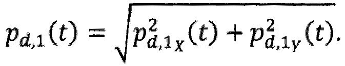
- Procédé selon les revendications 7 ou 8,
caractérisé en ce que
le signal de pression démodulé (p d,1(t)) est intégré et/ou en ce que le signal de pression est amplifié avant sa démodulation. - Procédé selon l'une des revendications 5 à 9,
caractérisé en ce qu'il comprend en outre :- la modification du volume du réservoir (5) selon un second signal initial (S 2(t)) par un second changement de volume (ΔV 2),- l'obtention d'un second signal de pression (p 2(t)) représentatif de la pression dans le réservoir (5) en fonction du temps (t), et- la démodulation du signal de pression (p 2(t)) à l'aide du second signal initial (S 2(t)) en tant que signal de référence, obtenant ainsi un second signal de pression démodulé (p d,2(t)). - Procédé selon l'une des revendications 5 à 10,
caractérisé en ce que :- la modification du volume du réservoir (5) selon un signal initial (S(t)) comprend la modification du volume par un premier changement de volume (ΔV 1) selon un premier signal initial (S1 (t)) et en même temps par un second changement de volume (ΔV 2) selon un second signal initial (S 2(t)) en même temps en modulant le volume avec une superposition des premiers et seconds changements de volume (ΔV 1, ΔV 2),- la démodulation du signal de pression (p(t)) comprend l'utilisation du premier signal initial (S 1(t)) en tant que signal de référence obtenant ainsi un premier signal de pression démodulé (p d,1) et l'utilisation du second signal initial (S 2(t)) en tant que signal de référence, obtenant ainsi un second signal de pression démodulé (p d,2). - Procédé selon la revendication 11,
caractérisé en ce que
le volume de gaz Vg (t) à l'intérieur du réservoir (5) suit Vg (t) = V 0 + ΔV 1·S 1(t) + ΔV 2(t)·S 2(t), dans lequel V 0 est une constante, ΔV 1, ΔV 2 sont lesdits premier et second changements de volume et S 1(t), S 2(t) sont lesdits premier et second signaux initiaux. - Procédé selon la revendication 11 ou 12,
caractérisé en ce que,
pour les premier et second signaux, l'équation S1(t) ≠ γ·S 2(t) se vérifie pour n'importe quelle constante yet/ou en ce que
au moins le premier signal initial (S 1(t)) est périodique et a une fréquence angulaire (ω), le procédé est répété avec des fréquences angulaires (ω) différentes, la fréquence de résonance est déterminée là où la valeur absolue du changement de pression devient maximale et en ce que le volume du gaz est déterminé d'après la fréquence de résonance.
Priority Applications (4)
| Application Number | Priority Date | Filing Date | Title |
|---|---|---|---|
| EP16156174.1A EP3208577B1 (fr) | 2016-02-17 | 2016-02-17 | Procédé et appareil de détection du niveau de liquide dans un réservoir de liquide |
| PCT/EP2017/053409 WO2017140732A1 (fr) | 2016-02-17 | 2017-02-15 | Procédé et appareil de détection de niveau de liquide dans un réservoir de liquide |
| CN201780011424.XA CN108700451B (zh) | 2016-02-17 | 2017-02-15 | 检测液体贮存器中液体水平的方法和设备 |
| US16/104,710 US10866132B2 (en) | 2016-02-17 | 2018-08-17 | Method and apparatus for detecting the liquid level in a liquid reservoir |
Applications Claiming Priority (1)
| Application Number | Priority Date | Filing Date | Title |
|---|---|---|---|
| EP16156174.1A EP3208577B1 (fr) | 2016-02-17 | 2016-02-17 | Procédé et appareil de détection du niveau de liquide dans un réservoir de liquide |
Publications (2)
| Publication Number | Publication Date |
|---|---|
| EP3208577A1 EP3208577A1 (fr) | 2017-08-23 |
| EP3208577B1 true EP3208577B1 (fr) | 2022-04-27 |
Family
ID=55435992
Family Applications (1)
| Application Number | Title | Priority Date | Filing Date |
|---|---|---|---|
| EP16156174.1A Active EP3208577B1 (fr) | 2016-02-17 | 2016-02-17 | Procédé et appareil de détection du niveau de liquide dans un réservoir de liquide |
Country Status (4)
| Country | Link |
|---|---|
| US (1) | US10866132B2 (fr) |
| EP (1) | EP3208577B1 (fr) |
| CN (1) | CN108700451B (fr) |
| WO (1) | WO2017140732A1 (fr) |
Families Citing this family (3)
| Publication number | Priority date | Publication date | Assignee | Title |
|---|---|---|---|---|
| DE102016113313A1 (de) * | 2016-07-19 | 2018-01-25 | Eagle Actuator Components Gmbh & Co. Kg | Temperaturkompensiertes Ventil |
| EP3376182A1 (fr) * | 2017-03-14 | 2018-09-19 | CSEM Centre Suisse D'electronique Et De Microtechnique SA | Système et procédé de distribution de fluide |
| IT201800002328A1 (it) * | 2018-02-02 | 2019-08-02 | Gd Spa | Metodo e stazione di misura per determinare il volume di prodotto liquido contenuto in una cartuccia monouso per articoli da fumo |
Family Cites Families (73)
| Publication number | Priority date | Publication date | Assignee | Title |
|---|---|---|---|---|
| US1945203A (en) * | 1929-02-24 | 1934-01-30 | Schiske Rudolf | Liquid level gauge |
| DE897331C (de) | 1941-12-25 | 1953-11-19 | Hans Dr Platzer | Verfahren zur Messung eines Behaelterinhaltes in bezug auf feste und/oder fluessige Stoffe |
| US3060735A (en) * | 1959-12-04 | 1962-10-30 | Owens Illinois Glass Co | Volumetric measurement |
| NL291810A (fr) * | 1962-04-20 | |||
| US3394590A (en) * | 1966-06-01 | 1968-07-30 | Hudson Eng Co | Hydraulic system and liquid level sensing mechanism therefor |
| US3453881A (en) * | 1966-12-19 | 1969-07-08 | Georgia Tech Res Inst | Method and apparatus for volume measurement |
| US4182178A (en) * | 1976-08-09 | 1980-01-08 | Texaco Inc. | Method and apparatus for measuring a change in surface level of a liquid |
| DE2937966C2 (de) * | 1979-09-20 | 1983-02-17 | Bosch und Pierburg System oHG, 4040 Neuss | Vorrichtung zum Messen der Füllmenge in einem Kraftstofftank |
| DE2953903C2 (de) | 1979-09-20 | 1985-06-05 | Pierburg Gmbh & Co Kg, 4040 Neuss | Vorrichtung zum Messen des Füllstandes |
| US4491016A (en) * | 1981-11-05 | 1985-01-01 | Pfister Gmbh | Method and apparatus for measuring the pressure of a fluid |
| US4474061A (en) | 1981-11-27 | 1984-10-02 | Motorola, Inc. | Sonic pressure volume measuring device |
| DE3206130C2 (de) * | 1982-02-20 | 1986-07-03 | Walter 2000 Hamburg Nicolai | Einrichtung zur Ermittlung und Anzeige der Menge eines flüssigen oder festen Lagergutes |
| US4509552A (en) * | 1983-04-18 | 1985-04-09 | Delta-X Corporation | Gas gun for determining the liquid level of a well |
| GB8317888D0 (en) * | 1983-07-01 | 1983-08-03 | Pond J B | System for measuring volumes |
| JPS617422A (ja) * | 1984-06-20 | 1986-01-14 | Ngk Spark Plug Co Ltd | 液面レベル検出方法 |
| DE3540768C1 (de) | 1985-11-16 | 1987-04-16 | Walter Nicolai | Verfahren und Vorrichtung zur Ermittlung und Anzeige der Menge eines fluessigen oder festen Lagerguts |
| US5349852A (en) * | 1986-03-04 | 1994-09-27 | Deka Products Limited Partnership | Pump controller using acoustic spectral analysis |
| US5575310A (en) * | 1986-03-04 | 1996-11-19 | Deka Products Limited Partnership | Flow control system with volume-measuring system using a resonatable mass |
| US4888718A (en) * | 1987-02-25 | 1989-12-19 | Kubushiki Kaisha Kosumo Keiki | Volume measuring apparatus and method |
| US4790183A (en) * | 1987-05-05 | 1988-12-13 | Beckman Instruments, Inc. | Acoustic impedance system for liquid boundary level detection |
| US4840064A (en) * | 1988-03-15 | 1989-06-20 | Sundstrand Corp. | Liquid volume monitoring apparatus and method |
| US4869097A (en) * | 1988-03-23 | 1989-09-26 | Rockwell International Corporation | Sonic gas pressure gauge |
| DE3913096A1 (de) * | 1989-04-21 | 1990-10-25 | Moto Meter Ag | Verfahren und vorrichtung zum messen einer fluessigkeitsmenge in einem behaelter |
| US4984457A (en) * | 1989-08-18 | 1991-01-15 | The United States Of America As Represented By The Administrator Of The National Aeronautics And Space Administration | Tank gauging apparatus and method |
| US5261274A (en) * | 1990-05-25 | 1993-11-16 | Daniel M. Nemirow | Dynamic volumetric instrument gauge |
| DE4042421A1 (de) * | 1990-06-02 | 1992-04-30 | Martin Lehmann | Verfahren und vorrichtung zum pruefen des volumens von behaeltnissen |
| US5105825A (en) * | 1990-07-10 | 1992-04-21 | Life Measurement Instruments | Method and apparatus for volume measurement and body composition estimation |
| US5586085A (en) * | 1991-10-31 | 1996-12-17 | Lichte; Leo J. | Container and adaptor for use with fluid volume sensor |
| WO1993025914A1 (fr) * | 1992-06-08 | 1993-12-23 | Behring Diagnostics, Inc. | Systeme de distribution de liquides |
| US5303586A (en) * | 1993-01-22 | 1994-04-19 | Wayne State University | Pressure or fluid level sensor |
| US5697346A (en) * | 1993-05-28 | 1997-12-16 | Servojet Products International | Method for using sonic gas-fueled internal combustion engine control system |
| DE4339933A1 (de) | 1993-11-24 | 1994-06-23 | Walter Nicolai | Verfahren und Einrichtung zur Verhütung der Kontamination des Umfeldes bei einem gegenüber der Atmosphäre absperrbaren Behälter mit Vorrichtung zur Ermittlung des Leervolumens oder des Restvolumens |
| US5726355A (en) * | 1995-03-13 | 1998-03-10 | Alcatel Network Systems, Inc. | Apparatus for detecting a change in volumetric integrity of an enclosure |
| JP3668860B2 (ja) * | 1996-07-23 | 2005-07-06 | 泰 石井 | 音響式体積計 |
| US7194893B2 (en) * | 1997-10-02 | 2007-03-27 | Siemens Canada Limited | Temperature correction method and subsystem for automotive evaporative leak detection systems |
| US6343505B1 (en) * | 1998-03-27 | 2002-02-05 | Siemens Canada Limited | Automotive evaporative leak detection system |
| US6470908B1 (en) * | 1999-11-19 | 2002-10-29 | Siemens Canada Limited | Pressure operable device for an integrated pressure management apparatus |
| US6474314B1 (en) * | 1999-11-19 | 2002-11-05 | Siemens Canada Limited | Fuel system with intergrated pressure management |
| US6478045B1 (en) * | 1999-11-19 | 2002-11-12 | Siemens Canada Limited | Solenoid for an integrated pressure management apparatus |
| US6502560B1 (en) * | 1999-11-19 | 2003-01-07 | Siemens Canada Limited | Integrated pressure management apparatus having electronic control circuit |
| US6474313B1 (en) * | 1999-11-19 | 2002-11-05 | Siemens Canada Limited | Connection between an integrated pressure management apparatus and a vapor collection canister |
| US6460566B1 (en) * | 1999-11-19 | 2002-10-08 | Siemens Canada Limited | Integrated pressure management system for a fuel system |
| US6983641B1 (en) * | 1999-11-19 | 2006-01-10 | Siemens Vdo Automotive Inc. | Method of managing pressure in a fuel system |
| US6484555B1 (en) * | 1999-11-19 | 2002-11-26 | Siemens Canada Limited | Method of calibrating an integrated pressure management apparatus |
| US6470861B1 (en) * | 1999-11-19 | 2002-10-29 | Siemens Canada Limited | Fluid flow through an integrated pressure management apparatus |
| US6450153B1 (en) * | 1999-11-19 | 2002-09-17 | Siemens Canada Limited | Integrated pressure management apparatus providing an on-board diagnostic |
| US6505514B1 (en) * | 1999-11-19 | 2003-01-14 | Siemens Canada Limited | Sensor arrangement for an integrated pressure management apparatus |
| US6453942B1 (en) * | 1999-11-19 | 2002-09-24 | Siemens Canada Limited | Housing for integrated pressure management apparatus |
| US6703635B2 (en) * | 2000-09-18 | 2004-03-09 | Ntt Advanced Technology Corporation | Method and apparatus for measuring the level of liquid using optical fiber strain gauge |
| US6931919B2 (en) * | 2001-06-29 | 2005-08-23 | Siemens Vdo Automotive Inc. | Diagnostic apparatus and method for an evaporative control system including an integrated pressure management apparatus |
| US6708552B2 (en) * | 2001-06-29 | 2004-03-23 | Siemens Automotive Inc. | Sensor arrangement for an integrated pressure management apparatus |
| US6951131B2 (en) * | 2002-09-06 | 2005-10-04 | Delphi Technologies, Inc. | Fuel level indication assembly |
| DE102004003893A1 (de) * | 2003-01-31 | 2004-08-12 | Luk Lamellen Und Kupplungsbau Beteiligungs Kg | Schieber für ein Schieberventil sowie Verfahren und Formwerkzeug zum Herstellen eines Schiebers |
| WO2004079467A1 (fr) * | 2003-03-07 | 2004-09-16 | Siemens Vdo Automotive Inc. | Regulateur de pression integre ameliore |
| DE10323063A1 (de) | 2003-05-20 | 2004-12-09 | Endress + Hauser Gmbh + Co. Kg | Verfahren zur Füllstandsmessung |
| DE10334032B4 (de) * | 2003-07-18 | 2005-06-23 | Ing. Erich Pfeiffer Gmbh | Ventileinrichtung |
| US7168297B2 (en) * | 2003-10-28 | 2007-01-30 | Environmental Systems Products Holdings Inc. | System and method for testing fuel tank integrity |
| GB0327026D0 (en) * | 2003-11-20 | 2003-12-24 | Intelligent | Volume measuring device |
| US9046402B2 (en) * | 2004-08-31 | 2015-06-02 | The Invention Sciencefund I, Llc | Method of measuring amount of substances in an ambient noise environment |
| DE102004047413A1 (de) | 2004-09-28 | 2006-03-30 | Endress + Hauser Gmbh + Co. Kg | Fertigungsseitiges Abgleichen eines Messgeräts zur kapazitiven Füllstandsmessung und entsprechendes Messgerät |
| US7347089B1 (en) | 2005-08-30 | 2008-03-25 | The United States Of America As Represented By The Administrator Of The National Aeronautics And Space Administration | Gas volume contents within a container, smart volume instrument |
| DE102007005619A1 (de) | 2007-01-31 | 2008-08-07 | Krohne S.A. | Füllstandsmeßvorrichtung |
| US8448665B1 (en) * | 2008-07-29 | 2013-05-28 | Perry R Anderson | Fuel overflow alarm system |
| DE102009026433A1 (de) | 2009-05-25 | 2010-12-09 | Endress + Hauser Gmbh + Co. Kg | Anordnung zur Füllstandsmessung mit einem mit Mikrowellen arbeitenden Füllstandsmessgerät |
| CA2773201C (fr) * | 2012-03-30 | 2019-06-25 | Gotohti.Com Inc. | Pompe a piston a debit variable |
| US9121743B2 (en) * | 2012-05-31 | 2015-09-01 | Rosemount Inc. | Process variable transmitter system with analog communication |
| JP5946176B2 (ja) * | 2012-07-13 | 2016-07-05 | 矢崎総業株式会社 | 内容量推定装置及びそれを有する内容量推定システム |
| EP2759812B1 (fr) | 2013-01-29 | 2018-01-17 | Rechner Industrie-Elektronik GmbH | Procédé et dispositif de mesure capacitive du niveau de remplissage de liquides ou produits en vrac |
| US10117985B2 (en) * | 2013-08-21 | 2018-11-06 | Fresenius Medical Care Holdings, Inc. | Determining a volume of medical fluid pumped into or out of a medical fluid cassette |
| US20150276088A1 (en) * | 2014-03-25 | 2015-10-01 | Hamilton Sundstrand Corporation | Pressure regulating valve and method of adjusting damping of the same |
| DE102014109836A1 (de) * | 2014-07-14 | 2016-01-14 | Hella Kgaa Hueck & Co. | Verfahren und Vorrichtung zum Bestimmen eines Volumens eines Nutzmediums in einem Vorratsbehälter |
| US10717102B2 (en) * | 2017-05-31 | 2020-07-21 | Thermochem Recovery International, Inc. | Pressure-based method and system for measuring the density and height of a fluidized bed |
| DE102017121426A1 (de) * | 2017-09-15 | 2019-03-21 | Marco Systemanalyse Und Entwicklung Gmbh | Verfahren zur Füllstandsermittlung |
-
2016
- 2016-02-17 EP EP16156174.1A patent/EP3208577B1/fr active Active
-
2017
- 2017-02-15 WO PCT/EP2017/053409 patent/WO2017140732A1/fr not_active Ceased
- 2017-02-15 CN CN201780011424.XA patent/CN108700451B/zh active Active
-
2018
- 2018-08-17 US US16/104,710 patent/US10866132B2/en active Active
Also Published As
| Publication number | Publication date |
|---|---|
| CN108700451A (zh) | 2018-10-23 |
| US20180356271A1 (en) | 2018-12-13 |
| CN108700451B (zh) | 2020-06-16 |
| EP3208577A1 (fr) | 2017-08-23 |
| WO2017140732A1 (fr) | 2017-08-24 |
| US10866132B2 (en) | 2020-12-15 |
Similar Documents
| Publication | Publication Date | Title |
|---|---|---|
| US10866132B2 (en) | Method and apparatus for detecting the liquid level in a liquid reservoir | |
| EP1406005B1 (fr) | Méthode et appareil de surveillance de valves de commande | |
| US7393187B2 (en) | Diaphragm pump with integrated pressure sensor | |
| US7278625B2 (en) | Metering valve | |
| US9279432B2 (en) | Media separating device, in particular hydraulic accumulator, including associated measuring apparatus and measuring method | |
| RU2010138453A (ru) | Способ диагностики обнаружения отказа компонента регулирующего клапана | |
| EP3665372B1 (fr) | Ensemble capteur de niveau | |
| EP2773926B1 (fr) | Appareil et procédé d'étalonnage à piston | |
| ATE483959T1 (de) | Verfahren und vorrichtung zur diagnose von flüssigkeitsverlusten in mit druck übertragenden flüssigkeiten gefüllten druckmessaufnehmern | |
| WO2007084909A1 (fr) | Detecteur de fuites | |
| US9046442B2 (en) | Method and apparatus for operating an injection valve | |
| US11085349B2 (en) | Monitoring a pressure sensor in a hydraulic system of a motor vehicle | |
| EP2780561B1 (fr) | Unité de distribution pour distribuer un additif liquide | |
| RU2344380C1 (ru) | Способ измерения объема жидкости в закрытом резервуаре | |
| EP1249695A2 (fr) | Dispositif actif de suppression des impulsions de pression pour un système d'échantillonnage de particules diesel | |
| WO2006117376A3 (fr) | Procede et dispositif pour diagnostiquer des composantes mecaniques, electromecaniques ou fluidiques | |
| US12196201B2 (en) | Hydraulic pressure amplifier | |
| EP2455600A1 (fr) | Procédé et dispositif de commande d'une soupape d'injection | |
| KR101643255B1 (ko) | 차량용 퍼지제어솔레노이드밸브 실차모사 측정 장치 | |
| KR20190098057A (ko) | Scr 촉매 컨버터 시스템용 에뮬레이터 검출 방법 | |
| EP1998037B1 (fr) | Diagnostic de fuite de gaz | |
| KR102730572B1 (ko) | 내연 기관의 연료 증발 보유 시스템을 진단하기 위한 방법 및 디바이스 | |
| KR20050034788A (ko) | 이지알 밸브의 성능시험장치 | |
| US5563337A (en) | Moisture monitor apparatus for a fluid system | |
| RU2660053C1 (ru) | Пробоотборник для отбора пробы жидкости, приспособленный для установки в системе с вариациями давления |
Legal Events
| Date | Code | Title | Description |
|---|---|---|---|
| PUAI | Public reference made under article 153(3) epc to a published international application that has entered the european phase |
Free format text: ORIGINAL CODE: 0009012 |
|
| STAA | Information on the status of an ep patent application or granted ep patent |
Free format text: STATUS: THE APPLICATION HAS BEEN PUBLISHED |
|
| AK | Designated contracting states |
Kind code of ref document: A1 Designated state(s): AL AT BE BG CH CY CZ DE DK EE ES FI FR GB GR HR HU IE IS IT LI LT LU LV MC MK MT NL NO PL PT RO RS SE SI SK SM TR |
|
| AX | Request for extension of the european patent |
Extension state: BA ME |
|
| RAP1 | Party data changed (applicant data changed or rights of an application transferred) |
Owner name: HELLA GMBH & CO. KGAA |
|
| STAA | Information on the status of an ep patent application or granted ep patent |
Free format text: STATUS: REQUEST FOR EXAMINATION WAS MADE |
|
| 17P | Request for examination filed |
Effective date: 20180112 |
|
| RBV | Designated contracting states (corrected) |
Designated state(s): AL AT BE BG CH CY CZ DE DK EE ES FI FR GB GR HR HU IE IS IT LI LT LU LV MC MK MT NL NO PL PT RO RS SE SI SK SM TR |
|
| RIC1 | Information provided on ipc code assigned before grant |
Ipc: G01F 22/02 20060101AFI20210519BHEP Ipc: G01F 23/00 20060101ALI20210519BHEP Ipc: G01F 17/00 20060101ALN20210519BHEP Ipc: G01F 23/14 20060101ALN20210519BHEP Ipc: G01F 23/18 20060101ALN20210519BHEP |
|
| GRAP | Despatch of communication of intention to grant a patent |
Free format text: ORIGINAL CODE: EPIDOSNIGR1 |
|
| STAA | Information on the status of an ep patent application or granted ep patent |
Free format text: STATUS: GRANT OF PATENT IS INTENDED |
|
| RIC1 | Information provided on ipc code assigned before grant |
Ipc: G01F 22/02 20060101AFI20210609BHEP Ipc: G01F 23/00 20060101ALI20210609BHEP Ipc: G01F 17/00 20060101ALN20210609BHEP Ipc: G01F 23/14 20060101ALN20210609BHEP Ipc: G01F 23/18 20060101ALN20210609BHEP |
|
| INTG | Intention to grant announced |
Effective date: 20210625 |
|
| GRAJ | Information related to disapproval of communication of intention to grant by the applicant or resumption of examination proceedings by the epo deleted |
Free format text: ORIGINAL CODE: EPIDOSDIGR1 |
|
| STAA | Information on the status of an ep patent application or granted ep patent |
Free format text: STATUS: REQUEST FOR EXAMINATION WAS MADE |
|
| INTC | Intention to grant announced (deleted) | ||
| GRAS | Grant fee paid |
Free format text: ORIGINAL CODE: EPIDOSNIGR3 |
|
| STAA | Information on the status of an ep patent application or granted ep patent |
Free format text: STATUS: GRANT OF PATENT IS INTENDED |
|
| RIC1 | Information provided on ipc code assigned before grant |
Ipc: G01F 23/18 20060101ALN20211217BHEP Ipc: G01F 23/14 20060101ALN20211217BHEP Ipc: G01F 17/00 20060101ALN20211217BHEP Ipc: G01F 23/00 20060101ALI20211217BHEP Ipc: G01F 22/02 20060101AFI20211217BHEP |
|
| GRAP | Despatch of communication of intention to grant a patent |
Free format text: ORIGINAL CODE: EPIDOSNIGR1 |
|
| INTG | Intention to grant announced |
Effective date: 20220128 |
|
| RIC1 | Information provided on ipc code assigned before grant |
Ipc: G01F 23/18 20060101ALN20220117BHEP Ipc: G01F 23/14 20060101ALN20220117BHEP Ipc: G01F 17/00 20060101ALN20220117BHEP Ipc: G01F 23/00 20060101ALI20220117BHEP Ipc: G01F 22/02 20060101AFI20220117BHEP |
|
| GRAA | (expected) grant |
Free format text: ORIGINAL CODE: 0009210 |
|
| STAA | Information on the status of an ep patent application or granted ep patent |
Free format text: STATUS: THE PATENT HAS BEEN GRANTED |
|
| AK | Designated contracting states |
Kind code of ref document: B1 Designated state(s): AL AT BE BG CH CY CZ DE DK EE ES FI FR GB GR HR HU IE IS IT LI LT LU LV MC MK MT NL NO PL PT RO RS SE SI SK SM TR |
|
| REG | Reference to a national code |
Ref country code: GB Ref legal event code: FG4D |
|
| REG | Reference to a national code |
Ref country code: CH Ref legal event code: EP |
|
| REG | Reference to a national code |
Ref country code: DE Ref legal event code: R096 Ref document number: 602016071442 Country of ref document: DE |
|
| REG | Reference to a national code |
Ref country code: AT Ref legal event code: REF Ref document number: 1487267 Country of ref document: AT Kind code of ref document: T Effective date: 20220515 |
|
| REG | Reference to a national code |
Ref country code: IE Ref legal event code: FG4D |
|
| REG | Reference to a national code |
Ref country code: LT Ref legal event code: MG9D |
|
| REG | Reference to a national code |
Ref country code: NL Ref legal event code: MP Effective date: 20220427 |
|
| REG | Reference to a national code |
Ref country code: AT Ref legal event code: MK05 Ref document number: 1487267 Country of ref document: AT Kind code of ref document: T Effective date: 20220427 |
|
| PG25 | Lapsed in a contracting state [announced via postgrant information from national office to epo] |
Ref country code: NL Free format text: LAPSE BECAUSE OF FAILURE TO SUBMIT A TRANSLATION OF THE DESCRIPTION OR TO PAY THE FEE WITHIN THE PRESCRIBED TIME-LIMIT Effective date: 20220427 |
|
| PG25 | Lapsed in a contracting state [announced via postgrant information from national office to epo] |
Ref country code: SE Free format text: LAPSE BECAUSE OF FAILURE TO SUBMIT A TRANSLATION OF THE DESCRIPTION OR TO PAY THE FEE WITHIN THE PRESCRIBED TIME-LIMIT Effective date: 20220427 Ref country code: PT Free format text: LAPSE BECAUSE OF FAILURE TO SUBMIT A TRANSLATION OF THE DESCRIPTION OR TO PAY THE FEE WITHIN THE PRESCRIBED TIME-LIMIT Effective date: 20220829 Ref country code: NO Free format text: LAPSE BECAUSE OF FAILURE TO SUBMIT A TRANSLATION OF THE DESCRIPTION OR TO PAY THE FEE WITHIN THE PRESCRIBED TIME-LIMIT Effective date: 20220727 Ref country code: LT Free format text: LAPSE BECAUSE OF FAILURE TO SUBMIT A TRANSLATION OF THE DESCRIPTION OR TO PAY THE FEE WITHIN THE PRESCRIBED TIME-LIMIT Effective date: 20220427 Ref country code: HR Free format text: LAPSE BECAUSE OF FAILURE TO SUBMIT A TRANSLATION OF THE DESCRIPTION OR TO PAY THE FEE WITHIN THE PRESCRIBED TIME-LIMIT Effective date: 20220427 Ref country code: GR Free format text: LAPSE BECAUSE OF FAILURE TO SUBMIT A TRANSLATION OF THE DESCRIPTION OR TO PAY THE FEE WITHIN THE PRESCRIBED TIME-LIMIT Effective date: 20220728 Ref country code: FI Free format text: LAPSE BECAUSE OF FAILURE TO SUBMIT A TRANSLATION OF THE DESCRIPTION OR TO PAY THE FEE WITHIN THE PRESCRIBED TIME-LIMIT Effective date: 20220427 Ref country code: ES Free format text: LAPSE BECAUSE OF FAILURE TO SUBMIT A TRANSLATION OF THE DESCRIPTION OR TO PAY THE FEE WITHIN THE PRESCRIBED TIME-LIMIT Effective date: 20220427 Ref country code: BG Free format text: LAPSE BECAUSE OF FAILURE TO SUBMIT A TRANSLATION OF THE DESCRIPTION OR TO PAY THE FEE WITHIN THE PRESCRIBED TIME-LIMIT Effective date: 20220727 Ref country code: AT Free format text: LAPSE BECAUSE OF FAILURE TO SUBMIT A TRANSLATION OF THE DESCRIPTION OR TO PAY THE FEE WITHIN THE PRESCRIBED TIME-LIMIT Effective date: 20220427 |
|
| PG25 | Lapsed in a contracting state [announced via postgrant information from national office to epo] |
Ref country code: RS Free format text: LAPSE BECAUSE OF FAILURE TO SUBMIT A TRANSLATION OF THE DESCRIPTION OR TO PAY THE FEE WITHIN THE PRESCRIBED TIME-LIMIT Effective date: 20220427 Ref country code: PL Free format text: LAPSE BECAUSE OF FAILURE TO SUBMIT A TRANSLATION OF THE DESCRIPTION OR TO PAY THE FEE WITHIN THE PRESCRIBED TIME-LIMIT Effective date: 20220427 Ref country code: LV Free format text: LAPSE BECAUSE OF FAILURE TO SUBMIT A TRANSLATION OF THE DESCRIPTION OR TO PAY THE FEE WITHIN THE PRESCRIBED TIME-LIMIT Effective date: 20220427 Ref country code: IS Free format text: LAPSE BECAUSE OF FAILURE TO SUBMIT A TRANSLATION OF THE DESCRIPTION OR TO PAY THE FEE WITHIN THE PRESCRIBED TIME-LIMIT Effective date: 20220827 |
|
| REG | Reference to a national code |
Ref country code: DE Ref legal event code: R097 Ref document number: 602016071442 Country of ref document: DE |
|
| PG25 | Lapsed in a contracting state [announced via postgrant information from national office to epo] |
Ref country code: SM Free format text: LAPSE BECAUSE OF FAILURE TO SUBMIT A TRANSLATION OF THE DESCRIPTION OR TO PAY THE FEE WITHIN THE PRESCRIBED TIME-LIMIT Effective date: 20220427 Ref country code: SK Free format text: LAPSE BECAUSE OF FAILURE TO SUBMIT A TRANSLATION OF THE DESCRIPTION OR TO PAY THE FEE WITHIN THE PRESCRIBED TIME-LIMIT Effective date: 20220427 Ref country code: RO Free format text: LAPSE BECAUSE OF FAILURE TO SUBMIT A TRANSLATION OF THE DESCRIPTION OR TO PAY THE FEE WITHIN THE PRESCRIBED TIME-LIMIT Effective date: 20220427 Ref country code: EE Free format text: LAPSE BECAUSE OF FAILURE TO SUBMIT A TRANSLATION OF THE DESCRIPTION OR TO PAY THE FEE WITHIN THE PRESCRIBED TIME-LIMIT Effective date: 20220427 Ref country code: DK Free format text: LAPSE BECAUSE OF FAILURE TO SUBMIT A TRANSLATION OF THE DESCRIPTION OR TO PAY THE FEE WITHIN THE PRESCRIBED TIME-LIMIT Effective date: 20220427 Ref country code: CZ Free format text: LAPSE BECAUSE OF FAILURE TO SUBMIT A TRANSLATION OF THE DESCRIPTION OR TO PAY THE FEE WITHIN THE PRESCRIBED TIME-LIMIT Effective date: 20220427 |
|
| PLBE | No opposition filed within time limit |
Free format text: ORIGINAL CODE: 0009261 |
|
| STAA | Information on the status of an ep patent application or granted ep patent |
Free format text: STATUS: NO OPPOSITION FILED WITHIN TIME LIMIT |
|
| PG25 | Lapsed in a contracting state [announced via postgrant information from national office to epo] |
Ref country code: AL Free format text: LAPSE BECAUSE OF FAILURE TO SUBMIT A TRANSLATION OF THE DESCRIPTION OR TO PAY THE FEE WITHIN THE PRESCRIBED TIME-LIMIT Effective date: 20220427 |
|
| 26N | No opposition filed |
Effective date: 20230130 |
|
| PG25 | Lapsed in a contracting state [announced via postgrant information from national office to epo] |
Ref country code: SI Free format text: LAPSE BECAUSE OF FAILURE TO SUBMIT A TRANSLATION OF THE DESCRIPTION OR TO PAY THE FEE WITHIN THE PRESCRIBED TIME-LIMIT Effective date: 20220427 |
|
| PG25 | Lapsed in a contracting state [announced via postgrant information from national office to epo] |
Ref country code: MC Free format text: LAPSE BECAUSE OF FAILURE TO SUBMIT A TRANSLATION OF THE DESCRIPTION OR TO PAY THE FEE WITHIN THE PRESCRIBED TIME-LIMIT Effective date: 20220427 |
|
| REG | Reference to a national code |
Ref country code: CH Ref legal event code: PL |
|
| REG | Reference to a national code |
Ref country code: BE Ref legal event code: MM Effective date: 20230228 |
|
| GBPC | Gb: european patent ceased through non-payment of renewal fee |
Effective date: 20230217 |
|
| PG25 | Lapsed in a contracting state [announced via postgrant information from national office to epo] |
Ref country code: LU Free format text: LAPSE BECAUSE OF NON-PAYMENT OF DUE FEES Effective date: 20230217 Ref country code: LI Free format text: LAPSE BECAUSE OF NON-PAYMENT OF DUE FEES Effective date: 20230228 Ref country code: CH Free format text: LAPSE BECAUSE OF NON-PAYMENT OF DUE FEES Effective date: 20230228 |
|
| REG | Reference to a national code |
Ref country code: IE Ref legal event code: MM4A |
|
| PG25 | Lapsed in a contracting state [announced via postgrant information from national office to epo] |
Ref country code: GB Free format text: LAPSE BECAUSE OF NON-PAYMENT OF DUE FEES Effective date: 20230217 |
|
| PG25 | Lapsed in a contracting state [announced via postgrant information from national office to epo] |
Ref country code: IT Free format text: LAPSE BECAUSE OF FAILURE TO SUBMIT A TRANSLATION OF THE DESCRIPTION OR TO PAY THE FEE WITHIN THE PRESCRIBED TIME-LIMIT Effective date: 20220427 Ref country code: IE Free format text: LAPSE BECAUSE OF NON-PAYMENT OF DUE FEES Effective date: 20230217 Ref country code: GB Free format text: LAPSE BECAUSE OF NON-PAYMENT OF DUE FEES Effective date: 20230217 |
|
| PG25 | Lapsed in a contracting state [announced via postgrant information from national office to epo] |
Ref country code: BE Free format text: LAPSE BECAUSE OF NON-PAYMENT OF DUE FEES Effective date: 20230228 |
|
| PG25 | Lapsed in a contracting state [announced via postgrant information from national office to epo] |
Ref country code: BG Free format text: LAPSE BECAUSE OF FAILURE TO SUBMIT A TRANSLATION OF THE DESCRIPTION OR TO PAY THE FEE WITHIN THE PRESCRIBED TIME-LIMIT Effective date: 20220427 |
|
| PG25 | Lapsed in a contracting state [announced via postgrant information from national office to epo] |
Ref country code: BG Free format text: LAPSE BECAUSE OF FAILURE TO SUBMIT A TRANSLATION OF THE DESCRIPTION OR TO PAY THE FEE WITHIN THE PRESCRIBED TIME-LIMIT Effective date: 20220427 |
|
| PG25 | Lapsed in a contracting state [announced via postgrant information from national office to epo] |
Ref country code: CY Free format text: LAPSE BECAUSE OF FAILURE TO SUBMIT A TRANSLATION OF THE DESCRIPTION OR TO PAY THE FEE WITHIN THE PRESCRIBED TIME-LIMIT; INVALID AB INITIO Effective date: 20160217 |
|
| PG25 | Lapsed in a contracting state [announced via postgrant information from national office to epo] |
Ref country code: HU Free format text: LAPSE BECAUSE OF FAILURE TO SUBMIT A TRANSLATION OF THE DESCRIPTION OR TO PAY THE FEE WITHIN THE PRESCRIBED TIME-LIMIT; INVALID AB INITIO Effective date: 20160217 |
|
| PG25 | Lapsed in a contracting state [announced via postgrant information from national office to epo] |
Ref country code: TR Free format text: LAPSE BECAUSE OF FAILURE TO SUBMIT A TRANSLATION OF THE DESCRIPTION OR TO PAY THE FEE WITHIN THE PRESCRIBED TIME-LIMIT Effective date: 20220427 |
|
| PGFP | Annual fee paid to national office [announced via postgrant information from national office to epo] |
Ref country code: FR Payment date: 20251222 Year of fee payment: 11 |
|
| PGFP | Annual fee paid to national office [announced via postgrant information from national office to epo] |
Ref country code: DE Payment date: 20251224 Year of fee payment: 11 |