EP3208876A1 - Luftabsperrhahnvorrichtung für ein brennstoffzellensystem - Google Patents
Luftabsperrhahnvorrichtung für ein brennstoffzellensystem Download PDFInfo
- Publication number
- EP3208876A1 EP3208876A1 EP16163116.3A EP16163116A EP3208876A1 EP 3208876 A1 EP3208876 A1 EP 3208876A1 EP 16163116 A EP16163116 A EP 16163116A EP 3208876 A1 EP3208876 A1 EP 3208876A1
- Authority
- EP
- European Patent Office
- Prior art keywords
- valve
- air passage
- air
- shut
- fuel cell
- Prior art date
- Legal status (The legal status is an assumption and is not a legal conclusion. Google has not performed a legal analysis and makes no representation as to the accuracy of the status listed.)
- Granted
Links
Images





Classifications
-
- H—ELECTRICITY
- H01—ELECTRIC ELEMENTS
- H01M—PROCESSES OR MEANS, e.g. BATTERIES, FOR THE DIRECT CONVERSION OF CHEMICAL ENERGY INTO ELECTRICAL ENERGY
- H01M8/00—Fuel cells; Manufacture thereof
- H01M8/04—Auxiliary arrangements, e.g. for control of pressure or for circulation of fluids
- H01M8/04082—Arrangements for control of reactant parameters, e.g. pressure or concentration
- H01M8/04201—Reactant storage and supply, e.g. means for feeding, pipes
-
- F—MECHANICAL ENGINEERING; LIGHTING; HEATING; WEAPONS; BLASTING
- F16—ENGINEERING ELEMENTS AND UNITS; GENERAL MEASURES FOR PRODUCING AND MAINTAINING EFFECTIVE FUNCTIONING OF MACHINES OR INSTALLATIONS; THERMAL INSULATION IN GENERAL
- F16K—VALVES; TAPS; COCKS; ACTUATING-FLOATS; DEVICES FOR VENTING OR AERATING
- F16K1/00—Lift valves or globe valves, i.e. cut-off apparatus with closure members having at least a component of their opening and closing motion perpendicular to the closing faces
- F16K1/16—Lift valves or globe valves, i.e. cut-off apparatus with closure members having at least a component of their opening and closing motion perpendicular to the closing faces with pivoted closure-members
- F16K1/18—Lift valves or globe valves, i.e. cut-off apparatus with closure members having at least a component of their opening and closing motion perpendicular to the closing faces with pivoted closure-members with pivoted discs or flaps
- F16K1/20—Lift valves or globe valves, i.e. cut-off apparatus with closure members having at least a component of their opening and closing motion perpendicular to the closing faces with pivoted closure-members with pivoted discs or flaps with axis of rotation arranged externally of valve member
- F16K1/2007—Lift valves or globe valves, i.e. cut-off apparatus with closure members having at least a component of their opening and closing motion perpendicular to the closing faces with pivoted closure-members with pivoted discs or flaps with axis of rotation arranged externally of valve member specially adapted operating means therefor
-
- F—MECHANICAL ENGINEERING; LIGHTING; HEATING; WEAPONS; BLASTING
- F16—ENGINEERING ELEMENTS AND UNITS; GENERAL MEASURES FOR PRODUCING AND MAINTAINING EFFECTIVE FUNCTIONING OF MACHINES OR INSTALLATIONS; THERMAL INSULATION IN GENERAL
- F16K—VALVES; TAPS; COCKS; ACTUATING-FLOATS; DEVICES FOR VENTING OR AERATING
- F16K1/00—Lift valves or globe valves, i.e. cut-off apparatus with closure members having at least a component of their opening and closing motion perpendicular to the closing faces
- F16K1/16—Lift valves or globe valves, i.e. cut-off apparatus with closure members having at least a component of their opening and closing motion perpendicular to the closing faces with pivoted closure-members
- F16K1/18—Lift valves or globe valves, i.e. cut-off apparatus with closure members having at least a component of their opening and closing motion perpendicular to the closing faces with pivoted closure-members with pivoted discs or flaps
- F16K1/20—Lift valves or globe valves, i.e. cut-off apparatus with closure members having at least a component of their opening and closing motion perpendicular to the closing faces with pivoted closure-members with pivoted discs or flaps with axis of rotation arranged externally of valve member
- F16K1/2021—Lift valves or globe valves, i.e. cut-off apparatus with closure members having at least a component of their opening and closing motion perpendicular to the closing faces with pivoted closure-members with pivoted discs or flaps with axis of rotation arranged externally of valve member with a plurality of valve members
-
- F—MECHANICAL ENGINEERING; LIGHTING; HEATING; WEAPONS; BLASTING
- F16—ENGINEERING ELEMENTS AND UNITS; GENERAL MEASURES FOR PRODUCING AND MAINTAINING EFFECTIVE FUNCTIONING OF MACHINES OR INSTALLATIONS; THERMAL INSULATION IN GENERAL
- F16K—VALVES; TAPS; COCKS; ACTUATING-FLOATS; DEVICES FOR VENTING OR AERATING
- F16K1/00—Lift valves or globe valves, i.e. cut-off apparatus with closure members having at least a component of their opening and closing motion perpendicular to the closing faces
- F16K1/16—Lift valves or globe valves, i.e. cut-off apparatus with closure members having at least a component of their opening and closing motion perpendicular to the closing faces with pivoted closure-members
- F16K1/18—Lift valves or globe valves, i.e. cut-off apparatus with closure members having at least a component of their opening and closing motion perpendicular to the closing faces with pivoted closure-members with pivoted discs or flaps
- F16K1/22—Lift valves or globe valves, i.e. cut-off apparatus with closure members having at least a component of their opening and closing motion perpendicular to the closing faces with pivoted closure-members with pivoted discs or flaps with axis of rotation crossing the valve member, e.g. butterfly valves
-
- F—MECHANICAL ENGINEERING; LIGHTING; HEATING; WEAPONS; BLASTING
- F16—ENGINEERING ELEMENTS AND UNITS; GENERAL MEASURES FOR PRODUCING AND MAINTAINING EFFECTIVE FUNCTIONING OF MACHINES OR INSTALLATIONS; THERMAL INSULATION IN GENERAL
- F16K—VALVES; TAPS; COCKS; ACTUATING-FLOATS; DEVICES FOR VENTING OR AERATING
- F16K31/00—Actuating devices; Operating means; Releasing devices
- F16K31/02—Actuating devices; Operating means; Releasing devices electric; magnetic
- F16K31/04—Actuating devices; Operating means; Releasing devices electric; magnetic using a motor
- F16K31/041—Actuating devices; Operating means; Releasing devices electric; magnetic using a motor for rotating valves
- F16K31/043—Actuating devices; Operating means; Releasing devices electric; magnetic using a motor for rotating valves characterised by mechanical means between the motor and the valve, e.g. lost motion means reducing backlash, clutches, brakes or return means
-
- H—ELECTRICITY
- H01—ELECTRIC ELEMENTS
- H01M—PROCESSES OR MEANS, e.g. BATTERIES, FOR THE DIRECT CONVERSION OF CHEMICAL ENERGY INTO ELECTRICAL ENERGY
- H01M8/00—Fuel cells; Manufacture thereof
- H01M8/04—Auxiliary arrangements, e.g. for control of pressure or for circulation of fluids
- H01M8/04082—Arrangements for control of reactant parameters, e.g. pressure or concentration
- H01M8/04089—Arrangements for control of reactant parameters, e.g. pressure or concentration of gaseous reactants
-
- H—ELECTRICITY
- H01—ELECTRIC ELEMENTS
- H01M—PROCESSES OR MEANS, e.g. BATTERIES, FOR THE DIRECT CONVERSION OF CHEMICAL ENERGY INTO ELECTRICAL ENERGY
- H01M8/00—Fuel cells; Manufacture thereof
- H01M8/04—Auxiliary arrangements, e.g. for control of pressure or for circulation of fluids
- H01M8/04223—Auxiliary arrangements, e.g. for control of pressure or for circulation of fluids during start-up or shut-down; Depolarisation or activation, e.g. purging; Means for short-circuiting defective fuel cells
-
- H—ELECTRICITY
- H01—ELECTRIC ELEMENTS
- H01M—PROCESSES OR MEANS, e.g. BATTERIES, FOR THE DIRECT CONVERSION OF CHEMICAL ENERGY INTO ELECTRICAL ENERGY
- H01M8/00—Fuel cells; Manufacture thereof
- H01M8/04—Auxiliary arrangements, e.g. for control of pressure or for circulation of fluids
- H01M8/04223—Auxiliary arrangements, e.g. for control of pressure or for circulation of fluids during start-up or shut-down; Depolarisation or activation, e.g. purging; Means for short-circuiting defective fuel cells
- H01M8/04228—Auxiliary arrangements, e.g. for control of pressure or for circulation of fluids during start-up or shut-down; Depolarisation or activation, e.g. purging; Means for short-circuiting defective fuel cells during shut-down
-
- H—ELECTRICITY
- H01—ELECTRIC ELEMENTS
- H01M—PROCESSES OR MEANS, e.g. BATTERIES, FOR THE DIRECT CONVERSION OF CHEMICAL ENERGY INTO ELECTRICAL ENERGY
- H01M8/00—Fuel cells; Manufacture thereof
- H01M8/04—Auxiliary arrangements, e.g. for control of pressure or for circulation of fluids
- H01M8/04082—Arrangements for control of reactant parameters, e.g. pressure or concentration
- H01M8/04089—Arrangements for control of reactant parameters, e.g. pressure or concentration of gaseous reactants
- H01M8/04119—Arrangements for control of reactant parameters, e.g. pressure or concentration of gaseous reactants with simultaneous supply or evacuation of electrolyte; Humidifying or dehumidifying
- H01M8/04126—Humidifying
- H01M8/04149—Humidifying by diffusion, e.g. making use of membranes
-
- Y—GENERAL TAGGING OF NEW TECHNOLOGICAL DEVELOPMENTS; GENERAL TAGGING OF CROSS-SECTIONAL TECHNOLOGIES SPANNING OVER SEVERAL SECTIONS OF THE IPC; TECHNICAL SUBJECTS COVERED BY FORMER USPC CROSS-REFERENCE ART COLLECTIONS [XRACs] AND DIGESTS
- Y02—TECHNOLOGIES OR APPLICATIONS FOR MITIGATION OR ADAPTATION AGAINST CLIMATE CHANGE
- Y02E—REDUCTION OF GREENHOUSE GAS [GHG] EMISSIONS, RELATED TO ENERGY GENERATION, TRANSMISSION OR DISTRIBUTION
- Y02E60/00—Enabling technologies; Technologies with a potential or indirect contribution to GHG emissions mitigation
- Y02E60/30—Hydrogen technology
- Y02E60/50—Fuel cells
Definitions
- the present disclosure relates to an air shut-off valve apparatus for a fuel cell system. More particularly, the present disclosure relates to an air shut-off valve apparatus for a fuel cell system with which an air passage connected to a cathode of a fuel cell stack can be completely closed upon the halt of operation of a fuel cell system.
- a fuel cell system is a system for converting the chemical energy from hydrogen fuel and oxygen in the air into electricity through a chemical reaction, with the concomitant production of water.
- a fuel cell vehicle is a type of vehicle that uses the electricity from a fuel cell system to power its on-board electric motor.
- a fuel cell system comprises a fuel cell stack, which generates electric energy and consists of a cathode (air electrode, oxygen electrode, reduction electrode) to which air is supplied, an anode (fuel electrode, hydrogen electrode, oxidation electrode) to which hydrogen is supplied, and an electrolyte membrane between the cathode and the anode.
- a cathode air electrode, oxygen electrode, reduction electrode
- an anode fuel electrode, hydrogen electrode, oxidation electrode
- the hydrogen supplied to an anode of the fuel cell stack is dissociated into protons (H+) and electrons (e-) by a catalyst. Only the protons move through the electrolyte membrane to the cathode, while the electrons are drawn from the anode to the cathode through a gas diffusion layer and a separator plate, which are both conductive.
- the protons and the electrons which are supplied through the electrolyte membrane and the separator plate, respectively, react together with oxygen in the air to produce water, with the resultant generation of electricity owing to the flow of the electrons through an external circuit as the protons migrate.
- an air shut-off valve apparatus for controlling air intake is installed on the cathode side of the fuel cell stack.
- an air shut-off valve apparatus which is typically installed on each of the inlet and outlet sides of an air passage that communicates with the cathode, should completely block the inflow of humid air into the cathode upon the halt of the fuel cell system.
- shut-off valve incompletely blocks the air passage communicating with the cathode when the fuel cell system is halted, humidified air continues to be introduced into the cathode, causing the corrosion and oxidation of a carbon support of the catalyst. As a result, the fuel cell stack deteriorates more rapidly, and thus decreases in durability.
- the introduction of humid air into the cathode while the fuel cell system is halted may increase the circuit voltages of individual cells to such an extent as to damage the fuel cell stack, thus requiring that the start-up COD (cathode oxygen depletion), which is adapted to consume the increased voltage of individual cells upon start-up, be provided with increased capacity.
- start-up COD cathode oxygen depletion
- an object of the present invention is to provide an air shut-off valve apparatus for a fuel cell system with which an air passage communicating with a cathode of a fuel cell stack can be completely closed, thus improving the durability of the fuel cell stack.
- an air shut-off valve apparatus for a fuel cell system, comprising: a valve body, in which an air passage communicates with a cathode of a fuel cell stack; and a valve flap, rotatably installed at the valve body, configured to open and close the air passage, wherein the valve body comprises a valve shaft that is axially rotatably installed at a position outside the air passage; and the valve flap is attached to the valve shaft at a position eccentric to the center of rotation of the valve shaft.
- the valve body may comprise a main body, at which the valve flap 20 is rotatably installed and which accounts for the external shape of the valve shut-off apparatus, and a sub-body, with which the valve flap is brought into contact when the air passage is closed by the valve flap and which is combined with the fuel cell stack in surface-contact.
- the sub-body may have a higher roughness than the main body.
- the sub-body may have a higher hardness than the main body.
- the main body may be die-cast from an aluminum alloy, and the sub-body may be made of stainless steel, or may be treated by hard anodizing if it is made of aluminum.
- the air passage may be divided into an inlet-side air passage and an outlet-side passage, both the inlet-side and the outlet-side passages being formed in one valve body, and a plurality of the valve flaps may be provided to cover the inlet-side air passage and the outlet-side air passage, respectively, and may be structured to open or close the inlet-side air passage and the outlet-side air passage at the same time.
- the air shut-off valve apparatus may further comprise: a valve motor installed in the main body; and valve gears through which the valve motor is connected to the valve shaft to transmit power of the valve motor to the valve shaft, wherein the valve shaft is axially rotatably mounted in the main body.
- valve flap may be adapted to completely cover an end of the air passage, whereby the air passage is made airtight.
- valve flap may comprise a valve plate, which is joined to the valve shaft, and a plate cover for covering the valve plate.
- the plate cover may be made of rubber so as to absorb noise and shocks upon contact with the sub-body and to improve the airtightness of the air passage.
- the air shut-off valve apparatus may further comprise a return spring, engaged at one end with the main body and at the other end with the valve shaft, for providing rotational torque for the valve shaft to move the valve flap in the direction in which the air passage is closed.
- the plate cover may have a cover projection incorporated thereinto, which comes into contact with a bulkhead forming the air passage in the sub-body, the cover projection may be brought into surface contact with the bulkhead in such a manner as to cover one end of the bulkhead, and an overlapping region may be provided between the cover projection and an end of the bulkhead so as to enhance the airtightness with which the air passage is closed by the valve flap.
- valve shaft may be positioned such that the center of rotation of the valve shaft is aligned with an end line of the bulkhead along a vertical line, and the valve plate may be attached to the valve shaft at a position eccentric to the center of rotation.
- valve flap may be eccentric to the center of rotation of the valve shaft by a distance equal to the projection length of the cover projection.
- valve flap when fully opened, may form an acute angle with respect to the closed state thereof.
- a closing force may be exerted for the valve flap to close the air passage, and simultaneously, a pressure difference may be formed between the inside and outside of the air passage closed by the valve flap.
- the air shut-off apparatus can achieve complete airtightness of the air passage even though a butterfly-type valve is used, and thus has advantages over a solenoid-type valve in terms of the number of parts, weight, and production cost.
- the complete closure of the air passage prevents the introduction of humidified air and foreign matter into the cathode of the fuel cell stack, thereby reducing the required capacity of the start-up COD (cathode oxygen depletion) and greatly enhancing the durability of the fuel cell system.
- Some forms of the present disclosure address an air shut-off valve for a fuel cell system, comprising, as shown in FIGS. 1 to 7 , a valve body 10, in which an air passage 11 communicates with a cathode la of a fuel cell stack 1, and a valve flap, rotatably installed in the valve body 10, for opening and closing the air passage 11.
- the air shut-off valve apparatus may be a butterfly-type valve, which has an advantage over a solenoid type in terms of cost.
- the air passage 11 formed in the valve body 10 may be divided into an inlet-side air passage 11a, through which humidified, external air is introduced into the cathode 1a of the fuel cell stack 1, and an outlet-side air passage 11b, through which air is drawn from the cathodes 1a.
- the inlet-side air passage 11a and the outlet-side air passage 11b are formed together in a single valve body 10, whereby the number and overall size of the valve apparatuses as well as the production cost thereof can be reduced.
- the inlet-side air passage 11a and the outlet-side air passage 11b may be positionally interchanged, unlike the positions shown in FIG. 1 .
- a plurality of the valve flaps 20 is provided to cover the inlet-side air passage 11a and the outlet-side air passage 11b, respectively. These plural valve flaps 20 are structured to open/close the inlet-side air passage 11a and the outlet-side air passage 11b at the same time.
- valve flaps 20 simultaneously close/open the inlet-side air passage 11a and the outlet-side air passage 11b requires only one set, comprising a power source and a power train, from the power source to the valve flaps 20, thus reducing the number of parts, the weight of the apparatus, and the production cost thereof.
- the air shut-off apparatus suffers from the disadvantage of increases in the number of parts, weight, production cost, and final size.
- the air shut-off is designed to simultaneously open or close both the inlet-side air passage 11a and the outlet-side air passage 11b with multiple valve flaps 20.
- the valve body 10 comprises a main body 12, at which the valve flaps 20 are rotatably installed and which accounts for the external shape of the valve shut-off apparatus, and a sub-body 13, with which the valve flaps 20 come into contact when the passages are closed by the valve flaps 20 and which is detachably engaged with the main body 12. Additionally, the sub-body 13 is combined with the fuel cell stack 1 in surface-contact.
- the sub-body 13 may be higher in roughness and hardness than the main body 12.
- the main body 12 may be die-cast from an aluminum alloy while the sub-body 13 may be made of stainless steel, or may be treated by hard anodizing when it is made of aluminum, to guarantee high roughness and hardness.
- the sub-body 13 is characterized by higher roughness than that of the main body 12 so as to improve the air-tightness (leakproofness) of the passages 11.
- the sub-body 13 is one of the most important factors in determining the airtightness of the air passages 11 upon closure with the valve flaps 20.
- the sub-body 13 is die-cast from an aluminum alloy alone, it is difficult to control the roughness of the air passages 11, and thus the airtightness of the air passages 11 becomes poor.
- the sub-body 13 is made of stainless steel, or is subjected to hard anodizing when die-cast from an aluminum alloy in the present disclosure.
- the sub-body 13 is higher in hardness than the main body 12 so that it can be prevented from being damaged by the valve flaps 20.
- the moisture in the air is apt to freeze during the winter season, causing minute damage to the sub-body 13 upon contact with the valve flaps 20.
- the sub-body 13 is made of stainless steel, or is subjected to hard anodizing when die-cast from an aluminum alloy so that the sub-body 13 has higher hardness than the main body 12.
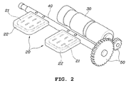
- the air shut-off valve apparatus may further comprise a valve motor 30, which is installed in the main body 12, a valve shaft 40, which is axially rotatably mounted in the main body 12 and to which a plurality of valve flaps 20 is fixedly engaged, and valve gears 50, through which the valve motor 30 is connected to the valve shaft 40 to transmit power from the valve motor 30 to the valve shaft 40.
- valve shaft 40 is mounted outside the air passages 11 so as to avoid causing resistance to the flow of air.
- the valve flaps 20 are adapted to completely cover ends of respective air passages 11 and thus to render the air passages 11 airtight.
- Each of the valve flaps 20 comprises a valve plate 21, which is made of steel or plastic and joined to the valve shaft 40, and a plate cover 22, made of rubber, for covering the valve plate so as to absorb noise and shocks upon contact with the sub-body 13 and to improve airtightness to the air passages 11.
- the air shut-off valve apparatus may further comprise a return spring 60, engaged at one end to the main body 12 and at the other end to the valve shaft 40, for providing rotational torque for the valve shaft 40 to move the valve flaps 20 in such a direction as to close the air passages 11.
- a return spring 60 engaged at one end to the main body 12 and at the other end to the valve shaft 40, for providing rotational torque for the valve shaft 40 to move the valve flaps 20 in such a direction as to close the air passages 11.
- Forms of the air shut-off valve apparatus are structured to rotate the valve shaft 40 using the power generated by the valve motor 30, during which the valve flaps 20 are rotated to close/open the air passages.
- the valve flaps 20 Upon the halt of operation of the fuel cell system (shut down), the valve flaps 20 should not only close the air passages 11, but should also guarantee the airtightness required by the fuel cell system.
- the return spring is provided in accordance with some forms of the present disclosure to prevent a fine gap from forming between the valve flaps 20 and the air passages 11 when the air passages are closed by the valve flaps 20.
- the elastic force of the return spring 40 should be greater than the reaction force of the plate cover 22 in the state in which the valve flaps 20 close the air passages 11.
- the return spring 60 should be designed to have optimal elastic force in consideration both of the elastic force of the plate cover 22, which is made of rubber, and of the power consumption of the valve motor 30.
- valve flaps 20 When the operation of the fuel cell system is halted (shut down), not only is a closing force exerted for the valve flaps 20 to close the air passages 11, but a pressure difference is also created between the inside and outside of the air passages 11 closed by the valve flaps 20. Accordingly, the valve flaps 20 can improve the airtightness of the air passages 11, thereby minimizing leakage.
- the restoring force of the return spring 60 compels the valve flaps 20 to close the air passages 11, and thus acts as the closing force of the valve flaps 20.
- the pressure of the air passages 11 on the side of the sub-body 13 based on the valve flaps 20 (outer pressure, P1 in FIG. 3 ) is lower than atmospheric pressure as the air reacts with residual gas in the stack.
- the pressure on the side of the main body 11 based on the valve flaps 20 (inner pressure, P2 in FIG. 2 ) is higher than the pressure of the air passages 11 on the side of the sub-body 13 (P1).
- valve flaps 20 when the operation of the fuel cell system is halted (shut down), the closing force of the valve flaps 20 is generated by the return spring 60 while a pressure difference is created between the inside and the outside on the basis of the valve flaps 20. These two factors enhance the ability of the valve flaps 29 to maintain the airtightness of the air passages 11, thus minimizing leakage.
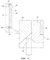
- the plate cover 22 has a cover projection 23 incorporated thereinto, which comes into contact with a bulkhead 13a forming the air passage 11 in the sub-body 13.
- the cover projection 23 is brought into surface contact with the bulkhead 13a in such a manner as to cover one end of the bulkhead 13a.
- M1 there is an overlapping region (M1) between the cover projection 23 and an end of the bulkhead 13a so as to enhance the airtightness with which the air passage is closed by the valve flap 20.
- the valve shaft 40 is positioned outside the air passages 11 such that the center of rotation (C1) of the valve shaft is aligned with the end line of the bulkhead 13a according to a vertical line (L1).
- the valve plate 21 is jointed to the valve shaft 40 at a position eccentric to the center of rotation (C1).
- the valve flap 20 has a structure that is eccentric to the center of rotation (C1) of the valve shaft 40 by a length equal to the projection length (L2) of the cover projection 23.
- butterfly-type valves are, for the most part, structured to have the valve plate 21 aligned with the center of rotation (C1) of the valve shaft 40, as shown in FIG. 7 .
- the cover projection 23 proximal to the center of rotation (C1) is first brought into contact with the bulkhead 13a of the sub-body 13 (upper cover projection in FIG. 7 ) while the cover projection 23 distal to the center of rotation (C1) remains spaced apart from the bulkhead 13a of the sub-body 13 (lower cover projection).
- the lower cover projection 23, which is spaced apart from the bulkhead 13a of the sub-body 13, must be in contact with the bulkhead 13a of the sub-body 13.
- the valve motor 30 is required to further operate, and the resistance occurring between the upper cover projection 23 and the bulkhead 13a increases the consumption of power. In severe cases, the valve motor may be damaged by fire.
- the valve flap 20 that is attached to the valve shaft 40 at a position eccentric to the center of rotation (C1) by a length equal to the projection length (L2) of the cover projection 23 in accordance with some embodiments of the present disclosure allows the cover projections 23, whether proximal (upper) or distal (lower) to the center of rotation (C1), to contact the bulkhead 13a of the sub-body 13, at the same time as the valve flap 20 moves to convert the air passage from an open state to a closed state.
- the valve motor 30 can be made to consume less power and can be prevented from being damaged by a fire in accordance with some embodiments of the present disclosure.
- valve flap 20 when fully opened, forms an acute angle ( ⁇ 1) with respect to its closed state.
- valve flap 20 When maximally opened, the valve flap 20 advantageously forms an acute angle ( ⁇ 1) with respect to the vertical line (L1, the closed state of the valve flap) to reduce the resistance to airflow and the final size of the air shut-off valve.
- the air shut-off apparatus can achieve complete airtightness of the air passage 11 even though a butterfly-type valve is used, and thus has advantages over a solenoid-type valve in terms of the number of parts, weight, and production cost.
- the complete closure of the air passage 11 prevents the introduction of foreign matter, thus enhancing the durability of the fuel cell system.
Landscapes
- Engineering & Computer Science (AREA)
- General Engineering & Computer Science (AREA)
- Sustainable Development (AREA)
- Life Sciences & Earth Sciences (AREA)
- Sustainable Energy (AREA)
- Chemical & Material Sciences (AREA)
- Chemical Kinetics & Catalysis (AREA)
- Electrochemistry (AREA)
- General Chemical & Material Sciences (AREA)
- Manufacturing & Machinery (AREA)
- Mechanical Engineering (AREA)
- Fuel Cell (AREA)
- Lift Valve (AREA)
- Valve Housings (AREA)
Applications Claiming Priority (1)
| Application Number | Priority Date | Filing Date | Title |
|---|---|---|---|
| KR1020160019048A KR20170097810A (ko) | 2016-02-18 | 2016-02-18 | 연료전지 시스템용 공기밸브 장치 |
Publications (3)
| Publication Number | Publication Date |
|---|---|
| EP3208876A1 true EP3208876A1 (de) | 2017-08-23 |
| EP3208876B1 EP3208876B1 (de) | 2019-05-08 |
| EP3208876B8 EP3208876B8 (de) | 2019-07-03 |
Family
ID=55646418
Family Applications (1)
| Application Number | Title | Priority Date | Filing Date |
|---|---|---|---|
| EP16163116.3A Active EP3208876B8 (de) | 2016-02-18 | 2016-03-31 | Luftabsperrhahnvorrichtung für ein brennstoffzellensystem |
Country Status (6)
| Country | Link |
|---|---|
| US (1) | US9911991B2 (de) |
| EP (1) | EP3208876B8 (de) |
| JP (2) | JP6795748B2 (de) |
| KR (1) | KR20170097810A (de) |
| CN (1) | CN107093754B (de) |
| DK (1) | DK3208876T3 (de) |
Families Citing this family (17)
| Publication number | Priority date | Publication date | Assignee | Title |
|---|---|---|---|---|
| KR20180069455A (ko) * | 2016-12-15 | 2018-06-25 | 주식회사 현대케피코 | 차량용 연료전지 스택의 공기차단밸브 |
| KR102383253B1 (ko) * | 2017-10-24 | 2022-04-05 | 현대자동차 주식회사 | 밸브 장치 |
| KR102452699B1 (ko) | 2017-12-20 | 2022-10-11 | 현대자동차주식회사 | 응축수 유입을 방지하는 공기 차단기 |
| KR102039636B1 (ko) * | 2017-12-27 | 2019-11-01 | 주식회사 현대케피코 | 공기차단밸브의 실링 구조 |
| KR102002229B1 (ko) * | 2017-12-27 | 2019-07-19 | 주식회사 현대케피코 | 공기차단밸브의 자가 정렬구조 |
| DE102018102062A1 (de) * | 2018-01-30 | 2019-08-01 | Protechna S.A. | Entnahmearmatur für Flüssigkeitsbehälter |
| KR102664114B1 (ko) * | 2018-11-20 | 2024-05-10 | 현대자동차주식회사 | 연료전지 시스템용 공기밸브 장치 |
| KR102673298B1 (ko) * | 2018-12-07 | 2024-06-10 | 현대자동차주식회사 | 연료전지 시스템용 공기밸브 장치 |
| KR102654843B1 (ko) * | 2019-01-02 | 2024-04-05 | 현대자동차주식회사 | 연료전지 시스템용 공기밸브 장치 |
| JP7712912B2 (ja) * | 2019-07-31 | 2025-07-24 | アプライド マテリアルズ インコーポレイテッド | 分離バルブ |
| KR102751297B1 (ko) * | 2020-03-24 | 2025-01-09 | 현대자동차주식회사 | 연료전지 차량용 에어 컨트롤 밸브 |
| KR102923148B1 (ko) * | 2020-09-22 | 2026-02-06 | 현대자동차주식회사 | 연료전지 차량용 에어 컨트롤 밸브 |
| KR102325469B1 (ko) * | 2021-05-18 | 2021-11-15 | (주)사이언스프로버 | 진공 게이트 밸브 |
| DE102022202128A1 (de) * | 2022-03-02 | 2023-09-07 | Bing Power Systems Gmbh | Drosselklappenanordnung |
| KR102716517B1 (ko) * | 2022-11-22 | 2024-10-15 | 주식회사 현대케피코 | 면압 균일화 스윙타입 공기차단밸브 |
| KR102720044B1 (ko) * | 2022-11-22 | 2024-10-22 | 주식회사 현대케피코 | 2중 밀폐 수직립 적용 공기차단밸브 |
| KR102789664B1 (ko) | 2022-12-26 | 2025-04-01 | 주식회사 현대케피코 | 양압 기밀형 공기차단밸브 |
Citations (4)
| Publication number | Priority date | Publication date | Assignee | Title |
|---|---|---|---|---|
| DE10215913C1 (de) * | 2002-04-11 | 2003-10-02 | Daimler Chrysler Ag | Brennstoffzellensystem |
| DE102008035990A1 (de) * | 2008-08-01 | 2010-02-11 | Fraunhofer-Gesellschaft zur Förderung der angewandten Forschung e.V. | Ein Mikroventil und ein Verfahren zur Herstellung desselben |
| US20150068626A1 (en) * | 2013-09-10 | 2015-03-12 | BorgWarner Esslingen GmbH | Valve assembly |
| DE102013021507A1 (de) * | 2013-12-18 | 2015-06-18 | Daimler Ag | Brennstoffzellenanordnung |
Family Cites Families (38)
| Publication number | Priority date | Publication date | Assignee | Title |
|---|---|---|---|---|
| US3861646A (en) * | 1972-10-27 | 1975-01-21 | Dresser Ind | Dual sealing element valve for oil well pumps |
| JPS50128722U (de) | 1974-03-22 | 1975-10-22 | ||
| JPS5697664U (de) * | 1979-12-25 | 1981-08-03 | ||
| FR2487034B1 (fr) * | 1980-07-18 | 1985-09-27 | Pont A Mousson | Robinet a papillon |
| JPS58109670U (ja) * | 1982-01-22 | 1983-07-26 | トヨタ自動車株式会社 | リ−ドバルブ装置 |
| SE444976B (sv) | 1984-01-20 | 1986-05-20 | Agroingengor Ab | Ventilanordning med ett, med ett flertal anslutningar forsett, ventilhus |
| JPH0294979U (de) | 1989-01-17 | 1990-07-27 | ||
| JPH11294267A (ja) * | 1998-04-10 | 1999-10-26 | Hino Motors Ltd | エンジンの排ガス再循環装置 |
| US6135415A (en) * | 1998-07-30 | 2000-10-24 | Siemens Canada Limited | Exhaust gas recirculation assembly |
| US6622986B2 (en) * | 2000-06-27 | 2003-09-23 | Siemens Canada Limited | Regulator valve with spacing chamber |
| US6648018B2 (en) | 2000-06-27 | 2003-11-18 | Siemens Automotive Inc. | Bypass control valve |
| JP4351437B2 (ja) * | 2002-11-29 | 2009-10-28 | 株式会社ケーヒン | 燃料電池用圧力調整装置 |
| US6976359B2 (en) * | 2004-02-17 | 2005-12-20 | Turbonetics, Inc. | Wastegate for a turbocharged internal combustion engine |
| DE202005003123U1 (de) | 2005-02-26 | 2005-05-19 | Reiche, Dirk | Klappenventil |
| JP4687540B2 (ja) * | 2006-04-12 | 2011-05-25 | 株式会社デンソー | 流体制御弁 |
| JP2007317475A (ja) | 2006-05-25 | 2007-12-06 | Toyota Motor Corp | 燃料電池システム |
| JP2008075971A (ja) * | 2006-09-21 | 2008-04-03 | Nidec Sankyo Corp | ダンパー装置 |
| JP5023743B2 (ja) | 2007-03-09 | 2012-09-12 | トヨタ自動車株式会社 | 燃料電池システム |
| JP5217470B2 (ja) * | 2008-02-04 | 2013-06-19 | 日産自動車株式会社 | 燃料電池システム及びその酸化剤極密閉方法 |
| US8415067B2 (en) | 2008-02-14 | 2013-04-09 | GM Global Technology Operations LLC | Three-way diverter assembly for a fuel cell system |
| JP5328213B2 (ja) * | 2008-04-16 | 2013-10-30 | 本田技研工業株式会社 | 燃料電池システム |
| DE102008031280A1 (de) * | 2008-07-02 | 2010-02-04 | Pierburg Gmbh | Anordnung eines Brennstoffzellensystems und Verfahren zum Einschalten und Abschalten eines derartigen Anodengaskreislaufs eines Brennstoffzellensystems |
| DE202009018979U1 (de) * | 2008-10-01 | 2015-02-09 | Borgwarner Inc. | Wastegate mit variabler Strömung |
| CN101555966B (zh) * | 2008-12-31 | 2013-06-12 | 浙江华夏阀门有限公司 | 微观锯齿环密封对接结构 |
| KR101124985B1 (ko) * | 2009-06-19 | 2012-03-27 | 현대자동차주식회사 | 연료전지 스택용 통합형 밸브 장치 |
| KR101134646B1 (ko) | 2010-01-04 | 2012-04-09 | (주)모토닉 | 수소연료전지 차량용 전자제어식 공기차단밸브장치 |
| JP2011222356A (ja) | 2010-04-12 | 2011-11-04 | Honda Motor Co Ltd | 燃料電池システム |
| JP2011253740A (ja) * | 2010-06-03 | 2011-12-15 | Toyota Motor Corp | 燃料電池に酸化剤ガスを供給する流路に配置されるバルブ装置 |
| WO2012007989A1 (ja) | 2010-07-13 | 2012-01-19 | トヨタ自動車株式会社 | 燃料電池用配管ユニットおよびそれを備えた燃料電池ユニット、燃料電池システム |
| KR20120019764A (ko) | 2010-08-26 | 2012-03-07 | 현대자동차주식회사 | 연료전지 시스템용 공기차단밸브 |
| JP2012172519A (ja) * | 2011-02-17 | 2012-09-10 | Denso Corp | フラップバルブ |
| US20120264028A1 (en) * | 2011-04-18 | 2012-10-18 | GM Global Technology Operations LLC | Semi-passive backpressure control valve |
| KR101342538B1 (ko) * | 2011-11-01 | 2013-12-17 | (주) 디에이치홀딩스 | 공기차단밸브 및 이를 이용한 재시동안정화방법 |
| KR101490912B1 (ko) | 2012-12-07 | 2015-02-06 | 현대자동차 주식회사 | 연료전지스택의 공기차단밸브 |
| CN203926834U (zh) * | 2014-04-22 | 2014-11-05 | 微芯科技有限公司 | 节流装置 |
| KR101534746B1 (ko) | 2014-05-21 | 2015-07-07 | 현대자동차 주식회사 | 차량의 연료전지 복합 밸브 |
| JP2016122541A (ja) | 2014-12-24 | 2016-07-07 | トヨタ自動車株式会社 | 燃料電池システムの起動方法 |
| CN204756036U (zh) * | 2015-05-22 | 2015-11-11 | 天津斯维克阀业有限公司 | 一种止回阀 |
-
2016
- 2016-02-18 KR KR1020160019048A patent/KR20170097810A/ko not_active Ceased
- 2016-03-08 US US15/064,225 patent/US9911991B2/en active Active
- 2016-03-25 CN CN201610180377.9A patent/CN107093754B/zh active Active
- 2016-03-31 EP EP16163116.3A patent/EP3208876B8/de active Active
- 2016-03-31 DK DK16163116.3T patent/DK3208876T3/da active
- 2016-04-27 JP JP2016089738A patent/JP6795748B2/ja active Active
-
2020
- 2020-09-29 JP JP2020163952A patent/JP7013541B2/ja active Active
Patent Citations (4)
| Publication number | Priority date | Publication date | Assignee | Title |
|---|---|---|---|---|
| DE10215913C1 (de) * | 2002-04-11 | 2003-10-02 | Daimler Chrysler Ag | Brennstoffzellensystem |
| DE102008035990A1 (de) * | 2008-08-01 | 2010-02-11 | Fraunhofer-Gesellschaft zur Förderung der angewandten Forschung e.V. | Ein Mikroventil und ein Verfahren zur Herstellung desselben |
| US20150068626A1 (en) * | 2013-09-10 | 2015-03-12 | BorgWarner Esslingen GmbH | Valve assembly |
| DE102013021507A1 (de) * | 2013-12-18 | 2015-06-18 | Daimler Ag | Brennstoffzellenanordnung |
Also Published As
| Publication number | Publication date |
|---|---|
| JP6795748B2 (ja) | 2020-12-02 |
| JP7013541B2 (ja) | 2022-01-31 |
| KR20170097810A (ko) | 2017-08-29 |
| EP3208876B1 (de) | 2019-05-08 |
| JP2017147214A (ja) | 2017-08-24 |
| EP3208876B8 (de) | 2019-07-03 |
| JP2021005568A (ja) | 2021-01-14 |
| CN107093754A (zh) | 2017-08-25 |
| US9911991B2 (en) | 2018-03-06 |
| US20170244117A1 (en) | 2017-08-24 |
| DK3208876T3 (da) | 2019-08-05 |
| CN107093754B (zh) | 2021-04-27 |
Similar Documents
| Publication | Publication Date | Title |
|---|---|---|
| US9911991B2 (en) | Air shut-off valve apparatus for fuel cell system | |
| KR102635919B1 (ko) | 연료전지 시스템용 공기밸브 장치 및 그 제어방법 | |
| US8439328B2 (en) | Fluid control valve and fuel cell system | |
| JP5144124B2 (ja) | 燃料電池システム | |
| CN102738489B (zh) | 燃料电池系统及其发电停止方法 | |
| US20100196772A1 (en) | Fuel cell system | |
| US8399140B2 (en) | Fuel cell system | |
| US20090004530A1 (en) | Control valve with enhanced inner surface | |
| JP2012099220A (ja) | 燃料電池システム | |
| KR102654843B1 (ko) | 연료전지 시스템용 공기밸브 장치 | |
| US11688864B2 (en) | Fuel cell system | |
| JP2011222356A (ja) | 燃料電池システム | |
| US20100119912A1 (en) | Fuel cell system | |
| JP5149778B2 (ja) | 燃料電池システム | |
| JP5462133B2 (ja) | 燃料電池システム | |
| JP2009187701A (ja) | 燃料電池システム及びその酸化剤極密閉方法 | |
| KR20190109802A (ko) | 밸브 장치 | |
| JP7104747B2 (ja) | バタフライバルブ及び燃料電池システム | |
| KR20210061885A (ko) | 연료전지용 워터트랩 장치 | |
| KR100957369B1 (ko) | 연료전지의 공기극 개폐장치 | |
| KR102673298B1 (ko) | 연료전지 시스템용 공기밸브 장치 | |
| JP5221919B2 (ja) | 燃料電池システム | |
| JP2024154643A (ja) | 燃料電池制御装置、燃料電池制御方法及び燃料電池システム | |
| CN117766820A (zh) | 燃料电池系统 | |
| JP2005243613A (ja) | 固体高分子形燃料電池の運転方法 |
Legal Events
| Date | Code | Title | Description |
|---|---|---|---|
| PUAI | Public reference made under article 153(3) epc to a published international application that has entered the european phase |
Free format text: ORIGINAL CODE: 0009012 |
|
| STAA | Information on the status of an ep patent application or granted ep patent |
Free format text: STATUS: THE APPLICATION HAS BEEN PUBLISHED |
|
| AK | Designated contracting states |
Kind code of ref document: A1 Designated state(s): AL AT BE BG CH CY CZ DE DK EE ES FI FR GB GR HR HU IE IS IT LI LT LU LV MC MK MT NL NO PL PT RO RS SE SI SK SM TR |
|
| AX | Request for extension of the european patent |
Extension state: BA ME |
|
| STAA | Information on the status of an ep patent application or granted ep patent |
Free format text: STATUS: REQUEST FOR EXAMINATION WAS MADE |
|
| 17P | Request for examination filed |
Effective date: 20180220 |
|
| RBV | Designated contracting states (corrected) |
Designated state(s): AL AT BE BG CH CY CZ DE DK EE ES FI FR GB GR HR HU IE IS IT LI LT LU LV MC MK MT NL NO PL PT RO RS SE SI SK SM TR |
|
| STAA | Information on the status of an ep patent application or granted ep patent |
Free format text: STATUS: EXAMINATION IS IN PROGRESS |
|
| 17Q | First examination report despatched |
Effective date: 20180420 |
|
| GRAP | Despatch of communication of intention to grant a patent |
Free format text: ORIGINAL CODE: EPIDOSNIGR1 |
|
| STAA | Information on the status of an ep patent application or granted ep patent |
Free format text: STATUS: GRANT OF PATENT IS INTENDED |
|
| RIC1 | Information provided on ipc code assigned before grant |
Ipc: H01M 8/04082 20160101ALI20181011BHEP Ipc: F16K 1/18 20060101ALI20181011BHEP Ipc: H01M 8/04089 20160101AFI20181011BHEP Ipc: H01M 8/04223 20160101ALI20181011BHEP Ipc: H01M 8/04119 20160101ALN20181011BHEP |
|
| INTG | Intention to grant announced |
Effective date: 20181102 |
|
| GRAS | Grant fee paid |
Free format text: ORIGINAL CODE: EPIDOSNIGR3 |
|
| GRAA | (expected) grant |
Free format text: ORIGINAL CODE: 0009210 |
|
| STAA | Information on the status of an ep patent application or granted ep patent |
Free format text: STATUS: THE PATENT HAS BEEN GRANTED |
|
| AK | Designated contracting states |
Kind code of ref document: B1 Designated state(s): AL AT BE BG CH CY CZ DE DK EE ES FI FR GB GR HR HU IE IS IT LI LT LU LV MC MK MT NL NO PL PT RO RS SE SI SK SM TR |
|
| REG | Reference to a national code |
Ref country code: GB Ref legal event code: FG4D |
|
| REG | Reference to a national code |
Ref country code: CH Ref legal event code: EP Ref country code: AT Ref legal event code: REF Ref document number: 1131652 Country of ref document: AT Kind code of ref document: T Effective date: 20190515 |
|
| REG | Reference to a national code |
Ref country code: DE Ref legal event code: R081 Ref document number: 602016013471 Country of ref document: DE Owner name: KIA MOTORS CORPORATION, KR Free format text: FORMER OWNERS: DONG HEE INDUSTRIAL CO., LTD., ULSAN, KR; HYUNDAI MOTOR COMPANY, SEOUL, KR; KIA MOTORS CORPORATION, SEOUL, KR Ref country code: DE Ref legal event code: R081 Ref document number: 602016013471 Country of ref document: DE Owner name: HYUNDAI MOTOR COMPANY, KR Free format text: FORMER OWNERS: DONG HEE INDUSTRIAL CO., LTD., ULSAN, KR; HYUNDAI MOTOR COMPANY, SEOUL, KR; KIA MOTORS CORPORATION, SEOUL, KR |
|
| REG | Reference to a national code |
Ref country code: DE Ref legal event code: R096 Ref document number: 602016013471 Country of ref document: DE Ref country code: IE Ref legal event code: FG4D |
|
| RAP2 | Party data changed (patent owner data changed or rights of a patent transferred) |
Owner name: HYUNDAI MOTOR COMPANY Owner name: KIA MOTORS CORPORATION |
|
| REG | Reference to a national code |
Ref country code: CH Ref legal event code: PK Free format text: BERICHTIGUNG B8 |
|
| REG | Reference to a national code |
Ref country code: DK Ref legal event code: T3 Effective date: 20190731 |
|
| REG | Reference to a national code |
Ref country code: NO Ref legal event code: T2 Effective date: 20190508 |
|
| REG | Reference to a national code |
Ref country code: NL Ref legal event code: MP Effective date: 20190508 |
|
| REG | Reference to a national code |
Ref country code: LT Ref legal event code: MG4D |
|
| PG25 | Lapsed in a contracting state [announced via postgrant information from national office to epo] |
Ref country code: SE Free format text: LAPSE BECAUSE OF FAILURE TO SUBMIT A TRANSLATION OF THE DESCRIPTION OR TO PAY THE FEE WITHIN THE PRESCRIBED TIME-LIMIT Effective date: 20190508 Ref country code: NL Free format text: LAPSE BECAUSE OF FAILURE TO SUBMIT A TRANSLATION OF THE DESCRIPTION OR TO PAY THE FEE WITHIN THE PRESCRIBED TIME-LIMIT Effective date: 20190508 Ref country code: ES Free format text: LAPSE BECAUSE OF FAILURE TO SUBMIT A TRANSLATION OF THE DESCRIPTION OR TO PAY THE FEE WITHIN THE PRESCRIBED TIME-LIMIT Effective date: 20190508 Ref country code: LT Free format text: LAPSE BECAUSE OF FAILURE TO SUBMIT A TRANSLATION OF THE DESCRIPTION OR TO PAY THE FEE WITHIN THE PRESCRIBED TIME-LIMIT Effective date: 20190508 Ref country code: FI Free format text: LAPSE BECAUSE OF FAILURE TO SUBMIT A TRANSLATION OF THE DESCRIPTION OR TO PAY THE FEE WITHIN THE PRESCRIBED TIME-LIMIT Effective date: 20190508 Ref country code: HR Free format text: LAPSE BECAUSE OF FAILURE TO SUBMIT A TRANSLATION OF THE DESCRIPTION OR TO PAY THE FEE WITHIN THE PRESCRIBED TIME-LIMIT Effective date: 20190508 Ref country code: PT Free format text: LAPSE BECAUSE OF FAILURE TO SUBMIT A TRANSLATION OF THE DESCRIPTION OR TO PAY THE FEE WITHIN THE PRESCRIBED TIME-LIMIT Effective date: 20190908 Ref country code: AL Free format text: LAPSE BECAUSE OF FAILURE TO SUBMIT A TRANSLATION OF THE DESCRIPTION OR TO PAY THE FEE WITHIN THE PRESCRIBED TIME-LIMIT Effective date: 20190508 |
|
| PG25 | Lapsed in a contracting state [announced via postgrant information from national office to epo] |
Ref country code: GR Free format text: LAPSE BECAUSE OF FAILURE TO SUBMIT A TRANSLATION OF THE DESCRIPTION OR TO PAY THE FEE WITHIN THE PRESCRIBED TIME-LIMIT Effective date: 20190809 Ref country code: LV Free format text: LAPSE BECAUSE OF FAILURE TO SUBMIT A TRANSLATION OF THE DESCRIPTION OR TO PAY THE FEE WITHIN THE PRESCRIBED TIME-LIMIT Effective date: 20190508 Ref country code: BG Free format text: LAPSE BECAUSE OF FAILURE TO SUBMIT A TRANSLATION OF THE DESCRIPTION OR TO PAY THE FEE WITHIN THE PRESCRIBED TIME-LIMIT Effective date: 20190808 Ref country code: RS Free format text: LAPSE BECAUSE OF FAILURE TO SUBMIT A TRANSLATION OF THE DESCRIPTION OR TO PAY THE FEE WITHIN THE PRESCRIBED TIME-LIMIT Effective date: 20190508 |
|
| REG | Reference to a national code |
Ref country code: AT Ref legal event code: MK05 Ref document number: 1131652 Country of ref document: AT Kind code of ref document: T Effective date: 20190508 |
|
| PG25 | Lapsed in a contracting state [announced via postgrant information from national office to epo] |
Ref country code: AT Free format text: LAPSE BECAUSE OF FAILURE TO SUBMIT A TRANSLATION OF THE DESCRIPTION OR TO PAY THE FEE WITHIN THE PRESCRIBED TIME-LIMIT Effective date: 20190508 Ref country code: EE Free format text: LAPSE BECAUSE OF FAILURE TO SUBMIT A TRANSLATION OF THE DESCRIPTION OR TO PAY THE FEE WITHIN THE PRESCRIBED TIME-LIMIT Effective date: 20190508 Ref country code: CZ Free format text: LAPSE BECAUSE OF FAILURE TO SUBMIT A TRANSLATION OF THE DESCRIPTION OR TO PAY THE FEE WITHIN THE PRESCRIBED TIME-LIMIT Effective date: 20190508 Ref country code: RO Free format text: LAPSE BECAUSE OF FAILURE TO SUBMIT A TRANSLATION OF THE DESCRIPTION OR TO PAY THE FEE WITHIN THE PRESCRIBED TIME-LIMIT Effective date: 20190508 Ref country code: SK Free format text: LAPSE BECAUSE OF FAILURE TO SUBMIT A TRANSLATION OF THE DESCRIPTION OR TO PAY THE FEE WITHIN THE PRESCRIBED TIME-LIMIT Effective date: 20190508 |
|
| REG | Reference to a national code |
Ref country code: DE Ref legal event code: R097 Ref document number: 602016013471 Country of ref document: DE |
|
| PG25 | Lapsed in a contracting state [announced via postgrant information from national office to epo] |
Ref country code: SM Free format text: LAPSE BECAUSE OF FAILURE TO SUBMIT A TRANSLATION OF THE DESCRIPTION OR TO PAY THE FEE WITHIN THE PRESCRIBED TIME-LIMIT Effective date: 20190508 Ref country code: IT Free format text: LAPSE BECAUSE OF FAILURE TO SUBMIT A TRANSLATION OF THE DESCRIPTION OR TO PAY THE FEE WITHIN THE PRESCRIBED TIME-LIMIT Effective date: 20190508 |
|
| PLBE | No opposition filed within time limit |
Free format text: ORIGINAL CODE: 0009261 |
|
| STAA | Information on the status of an ep patent application or granted ep patent |
Free format text: STATUS: NO OPPOSITION FILED WITHIN TIME LIMIT |
|
| PG25 | Lapsed in a contracting state [announced via postgrant information from national office to epo] |
Ref country code: TR Free format text: LAPSE BECAUSE OF FAILURE TO SUBMIT A TRANSLATION OF THE DESCRIPTION OR TO PAY THE FEE WITHIN THE PRESCRIBED TIME-LIMIT Effective date: 20190508 |
|
| 26N | No opposition filed |
Effective date: 20200211 |
|
| PG25 | Lapsed in a contracting state [announced via postgrant information from national office to epo] |
Ref country code: PL Free format text: LAPSE BECAUSE OF FAILURE TO SUBMIT A TRANSLATION OF THE DESCRIPTION OR TO PAY THE FEE WITHIN THE PRESCRIBED TIME-LIMIT Effective date: 20190508 |
|
| PG25 | Lapsed in a contracting state [announced via postgrant information from national office to epo] |
Ref country code: SI Free format text: LAPSE BECAUSE OF FAILURE TO SUBMIT A TRANSLATION OF THE DESCRIPTION OR TO PAY THE FEE WITHIN THE PRESCRIBED TIME-LIMIT Effective date: 20190508 |
|
| PG25 | Lapsed in a contracting state [announced via postgrant information from national office to epo] |
Ref country code: MC Free format text: LAPSE BECAUSE OF FAILURE TO SUBMIT A TRANSLATION OF THE DESCRIPTION OR TO PAY THE FEE WITHIN THE PRESCRIBED TIME-LIMIT Effective date: 20190508 |
|
| REG | Reference to a national code |
Ref country code: CH Ref legal event code: PL |
|
| REG | Reference to a national code |
Ref country code: BE Ref legal event code: MM Effective date: 20200331 |
|
| PG25 | Lapsed in a contracting state [announced via postgrant information from national office to epo] |
Ref country code: LU Free format text: LAPSE BECAUSE OF NON-PAYMENT OF DUE FEES Effective date: 20200331 |
|
| PG25 | Lapsed in a contracting state [announced via postgrant information from national office to epo] |
Ref country code: IE Free format text: LAPSE BECAUSE OF NON-PAYMENT OF DUE FEES Effective date: 20200331 Ref country code: LI Free format text: LAPSE BECAUSE OF NON-PAYMENT OF DUE FEES Effective date: 20200331 Ref country code: CH Free format text: LAPSE BECAUSE OF NON-PAYMENT OF DUE FEES Effective date: 20200331 |
|
| PG25 | Lapsed in a contracting state [announced via postgrant information from national office to epo] |
Ref country code: BE Free format text: LAPSE BECAUSE OF NON-PAYMENT OF DUE FEES Effective date: 20200331 |
|
| PG25 | Lapsed in a contracting state [announced via postgrant information from national office to epo] |
Ref country code: MT Free format text: LAPSE BECAUSE OF FAILURE TO SUBMIT A TRANSLATION OF THE DESCRIPTION OR TO PAY THE FEE WITHIN THE PRESCRIBED TIME-LIMIT Effective date: 20190508 Ref country code: CY Free format text: LAPSE BECAUSE OF FAILURE TO SUBMIT A TRANSLATION OF THE DESCRIPTION OR TO PAY THE FEE WITHIN THE PRESCRIBED TIME-LIMIT Effective date: 20190508 |
|
| PG25 | Lapsed in a contracting state [announced via postgrant information from national office to epo] |
Ref country code: MK Free format text: LAPSE BECAUSE OF FAILURE TO SUBMIT A TRANSLATION OF THE DESCRIPTION OR TO PAY THE FEE WITHIN THE PRESCRIBED TIME-LIMIT Effective date: 20190508 Ref country code: IS Free format text: LAPSE BECAUSE OF FAILURE TO SUBMIT A TRANSLATION OF THE DESCRIPTION OR TO PAY THE FEE WITHIN THE PRESCRIBED TIME-LIMIT Effective date: 20190908 |
|
| P01 | Opt-out of the competence of the unified patent court (upc) registered |
Effective date: 20230504 |
|
| PGFP | Annual fee paid to national office [announced via postgrant information from national office to epo] |
Ref country code: GB Payment date: 20260224 Year of fee payment: 11 |
|
| PGFP | Annual fee paid to national office [announced via postgrant information from national office to epo] |
Ref country code: NO Payment date: 20260224 Year of fee payment: 11 Ref country code: DK Payment date: 20260223 Year of fee payment: 11 Ref country code: DE Payment date: 20260220 Year of fee payment: 11 |
|
| PGFP | Annual fee paid to national office [announced via postgrant information from national office to epo] |
Ref country code: FR Payment date: 20260224 Year of fee payment: 11 |