EP3208891A1 - Douille pour fiche électrique et prise électrique souple - Google Patents
Douille pour fiche électrique et prise électrique souple Download PDFInfo
- Publication number
- EP3208891A1 EP3208891A1 EP17154060.2A EP17154060A EP3208891A1 EP 3208891 A1 EP3208891 A1 EP 3208891A1 EP 17154060 A EP17154060 A EP 17154060A EP 3208891 A1 EP3208891 A1 EP 3208891A1
- Authority
- EP
- European Patent Office
- Prior art keywords
- socket
- contact elements
- elements
- isolation
- electrical
- Prior art date
- Legal status (The legal status is an assumption and is not a legal conclusion. Google has not performed a legal analysis and makes no representation as to the accuracy of the status listed.)
- Withdrawn
Links
- 239000000463 material Substances 0.000 claims abstract description 13
- 238000002955 isolation Methods 0.000 claims description 48
- 238000003780 insertion Methods 0.000 claims description 13
- 230000037431 insertion Effects 0.000 claims description 13
- 239000002184 metal Substances 0.000 claims description 9
- 239000004020 conductor Substances 0.000 claims description 6
- 229920001971 elastomer Polymers 0.000 description 3
- 239000000806 elastomer Substances 0.000 description 3
- 230000005236 sound signal Effects 0.000 description 3
- 238000010438 heat treatment Methods 0.000 description 2
- 239000011810 insulating material Substances 0.000 description 2
- -1 polypropylene Polymers 0.000 description 2
- 229920002635 polyurethane Polymers 0.000 description 2
- 239000004814 polyurethane Substances 0.000 description 2
- 229930040373 Paraformaldehyde Natural products 0.000 description 1
- 239000004743 Polypropylene Substances 0.000 description 1
- 230000006978 adaptation Effects 0.000 description 1
- 238000010276 construction Methods 0.000 description 1
- 238000001816 cooling Methods 0.000 description 1
- 238000011161 development Methods 0.000 description 1
- 230000018109 developmental process Effects 0.000 description 1
- 230000000149 penetrating effect Effects 0.000 description 1
- 229920006324 polyoxymethylene Polymers 0.000 description 1
- 229920001155 polypropylene Polymers 0.000 description 1
- 230000002035 prolonged effect Effects 0.000 description 1
- 238000005476 soldering Methods 0.000 description 1
Images
Classifications
-
- H—ELECTRICITY
- H01—ELECTRIC ELEMENTS
- H01R—ELECTRICALLY-CONDUCTIVE CONNECTIONS; STRUCTURAL ASSOCIATIONS OF A PLURALITY OF MUTUALLY-INSULATED ELECTRICAL CONNECTING ELEMENTS; COUPLING DEVICES; CURRENT COLLECTORS
- H01R13/00—Details of coupling devices of the kinds covered by groups H01R12/70 or H01R24/00 - H01R33/00
- H01R13/46—Bases; Cases
-
- H—ELECTRICITY
- H01—ELECTRIC ELEMENTS
- H01R—ELECTRICALLY-CONDUCTIVE CONNECTIONS; STRUCTURAL ASSOCIATIONS OF A PLURALITY OF MUTUALLY-INSULATED ELECTRICAL CONNECTING ELEMENTS; COUPLING DEVICES; CURRENT COLLECTORS
- H01R13/00—Details of coupling devices of the kinds covered by groups H01R12/70 or H01R24/00 - H01R33/00
- H01R13/02—Contact members
- H01R13/10—Sockets for co-operation with pins or blades
- H01R13/11—Resilient sockets
- H01R13/111—Resilient sockets co-operating with pins having a circular transverse section
-
- H—ELECTRICITY
- H01—ELECTRIC ELEMENTS
- H01R—ELECTRICALLY-CONDUCTIVE CONNECTIONS; STRUCTURAL ASSOCIATIONS OF A PLURALITY OF MUTUALLY-INSULATED ELECTRICAL CONNECTING ELEMENTS; COUPLING DEVICES; CURRENT COLLECTORS
- H01R13/00—Details of coupling devices of the kinds covered by groups H01R12/70 or H01R24/00 - H01R33/00
- H01R13/02—Contact members
- H01R13/03—Contact members characterised by the material, e.g. plating, or coating materials
-
- H—ELECTRICITY
- H01—ELECTRIC ELEMENTS
- H01R—ELECTRICALLY-CONDUCTIVE CONNECTIONS; STRUCTURAL ASSOCIATIONS OF A PLURALITY OF MUTUALLY-INSULATED ELECTRICAL CONNECTING ELEMENTS; COUPLING DEVICES; CURRENT COLLECTORS
- H01R13/00—Details of coupling devices of the kinds covered by groups H01R12/70 or H01R24/00 - H01R33/00
- H01R13/40—Securing contact members in or to a base or case; Insulating of contact members
-
- H—ELECTRICITY
- H01—ELECTRIC ELEMENTS
- H01R—ELECTRICALLY-CONDUCTIVE CONNECTIONS; STRUCTURAL ASSOCIATIONS OF A PLURALITY OF MUTUALLY-INSULATED ELECTRICAL CONNECTING ELEMENTS; COUPLING DEVICES; CURRENT COLLECTORS
- H01R24/00—Two-part coupling devices, or either of their cooperating parts, characterised by their overall structure
- H01R24/58—Contacts spaced along longitudinal axis of engagement
-
- H—ELECTRICITY
- H01—ELECTRIC ELEMENTS
- H01R—ELECTRICALLY-CONDUCTIVE CONNECTIONS; STRUCTURAL ASSOCIATIONS OF A PLURALITY OF MUTUALLY-INSULATED ELECTRICAL CONNECTING ELEMENTS; COUPLING DEVICES; CURRENT COLLECTORS
- H01R2107/00—Four or more poles
-
- H—ELECTRICITY
- H01—ELECTRIC ELEMENTS
- H01R—ELECTRICALLY-CONDUCTIVE CONNECTIONS; STRUCTURAL ASSOCIATIONS OF A PLURALITY OF MUTUALLY-INSULATED ELECTRICAL CONNECTING ELEMENTS; COUPLING DEVICES; CURRENT COLLECTORS
- H01R24/00—Two-part coupling devices, or either of their cooperating parts, characterised by their overall structure
- H01R24/60—Contacts spaced along planar side wall transverse to longitudinal axis of engagement
- H01R24/62—Sliding engagements with one side only, e.g. modular jack coupling devices
Definitions
- the disclosure relates to a socket for an electrical plug where the plug comprises two or more electrical contacts positioned on a longitudinal axis.
- the disclosure also relates to a correspondingly constructed electrical plug.
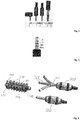
- Fig. 1 shows from left to right a 2.5 mm mono plug, a 3.5 mm mono plug, a 3.5 mm stereo plug and a 6.35 mm stereo plug.
- the two contact elements are called tip and sleeve (TS) in the case of the two mono plugs.
- TS tip and sleeve
- TRS tip, ring and sleeve
- Fig. 2 shows a 3.5 mm 4-conductor TRRS phone connector for stereo unbalanced audio signals plus video signals in the OMTP (Open Mobile Terminal Platform) variant.
- the tip contact L is for the left audio channel
- 1 st ring contact R is for the right audio channel
- 2 nd ring contact AUX is for an aux signal, e.g. microphone signal
- the sleeve contact GND is the back line for all signals (common ground).
- a D-shaped connector plug which includes a flexible portion that allows the connector to bend with respect to an insertion axis.
- the isolation elements may be made of flexible material and some inner elements, too.
- the stereo plug is often used for stereo headphones which are to be connected with an audio player like CD player, DVD player, mp3 player, smart phone, Camcorder, digital still camera or the like.
- a head tracking module detects the movement of the head typically in the form of detecting the azimuth angle in which the user has turned his head and the elevation angle in which the user has turned his head.
- the head tracking module monitors the position of the listener's head every 5 ms.
- different types of headphone plugs are needed which are equipped with more contact elements. At least two additional contact elements are needed, one for the azimuth signal and another for the elevation signal.
- Another object of the disclosure is to provide for an electrical socket which offers more freedom in regard to the positon where the socket can be placed in the player device.
- the contact elements of the socket are mounted along a curved line such that said electrical plug when inserted into the socket will be bent in the form of said curved line.
- This can shorten the socket arrangement in terms of the mounting length.
- This can also provide for more flexibility in terms of the position in the device where the socket can be placed. For example if the socket is curved to the right, the socket can be placed at a location closer to the left where a component inside the device is positioned such that at this position a socket in the classical straight form could not be placed.
- a socket could also be curved to the left when to the right where the socket shall be placed a hurdle is located.
- An aspect of the disclosure relates to a socket comprising a bendable socket body adapted for an insertion of at least a part of an electrical plug, said part being inserted in said socket body along an insertion line, the socket comprising two or more corresponding contact elements mounted on said bendable socket body along said insertion line.
- the socket comprises a straight part comprising at least two of said electrical contact elements, said two electrical contact elements being aligned together when said socket is bent, one of said two electrical contact element being a tip electrical contact element.
- the socket comprises one or more isolation elements which electrically isolate said electrical contact elements against each other.
- said isolation elements and/or said contact elements are formed in a wedge shape.
- said isolation elements are part of an isolation body and said contact elements are mounted at the socket each time between two isolation elements.
- said socket body is bendable in the form of a spiral.
- said isolation elements and/or said contact elements are formed in such a shape such that said contact elements are mounted in said socket along said curved line. This way it can be easy to assemble the socket from single parts.
- said isolation elements are part of a curved isolation body and said contact elements are mounted at the socket each time between two isolation elements. This way the assembling of the socket can even be simpler.
- said contact elements are made of metal in the form of contact springs or spring loaded pins.
- said curved line is in the form of a spiral.
- This shape of the socket can help reducing the length and width of the socket in an optimized way.
- the at least two first contact elements are positioned on a straight line. This way the socket can be made compatible to known mono or stereo jacks which are of smaller length but are rigid.
- the contact elements are made of a flexible material. This way, said electrical plug when inserted into a socket according to the disclosure can be bent in the form of the curved line of the socket.
- the plug comprises at least one isolation element for electrically isolating said two or more contact elements against each other, where said at least one isolation element is being made of flexible isolation material, too.
- a flexible realization of said contact elements is with the help of a braided conductor material, in particular braided metal.
- one or more isolation elements at the sleeve end which will not be bent when the plug is inserted into the curved socket have a smaller length than the remaining isolation elements at the tip end. This can be advantageous if the plug will be bent strongly when inserted into the curved socket, e.g. if the socket has spiral form.
- the plug comprising contact elements and/or the isolation elements is flat in one dimension. This supports that the plug will bent easily when inserted into the curved socket.
- the contact elements and/or the isolation elements may have cuboid form, wherein the cuboid is thin in one dimension.
- a flat cable can be used for connecting the contact elements inside the plug.
- An aspect of the present disclosure relates to a flexible electrical plug comprising two or more electrical contact elements being positioned along a longitudinal axis.
- said contact elements are constructed in a flexible material such that said electrical plug inserted into a socket according to one of the previous claims will be bent in the form of a curved line.
- the contact elements and/or the isolation elements have cuboid form, the cuboid being thin in one dimension.
- said contact elements are made of a braided conductor material, in particular braided metal.
- Another aspect of the disclosure relates to a device comprising a socket according to the present disclosure,according any of its embodiments.
- the device comprises a socket comprising a bendable socket body adapted for an insertion of at least a part of an electrical plug, said part being inserted in said socket body along an insertion line, the socket comprising two or more corresponding contact elements mounted on said bendable socket body along said insertion line.
- the socket comprises a straight part comprising at least two of said electrical contact elements, said two electrical contact elements being aligned together when said socket is bent, one of said two electrical contact element being a tip electrical contact element.
- the socket comprises one or more isolation elements which electrically isolate said electrical contact elements against each other.
- said isolation elements and/or said contact elements are formed in a wedge shape.
- said isolation elements are part of an isolation body and said contact elements are mounted at the socket each time between two isolation elements.
- said contact elements are made of metal in the form of contact springs or spring loaded pins.
- said socket body is bendable in the form of a spiral.
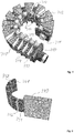
- Fig. 3 shows a first variant of the electrical socket according the disclosure.
- This variant is labelled with reference number 310.
- It consists of a socket body 311 which is made of an insulating material.
- the insulating material may be a rigid elastomer or polyurethane. As an alternative this may also be made of a flexible elastomer e.g. polypropylene or polyoxymethylene.
- the body of the jack socket also comprises a plurality of isolation elements 313.
- the isolation elements are an integrated part of the socket body.
- the isolation elements are separate elements which are attached to the socket body at predefined places. As illustrated in the drawing the isolation elements 313 are wedge shaped.
- the body of the socket 310 extends in longitudinal direction but is curved in this direction.
- the isolation elements 313 with wedge shape are positioned along the curve in equidistance, where the wide end of the wedges are positioned at the outer radius of the curve and the narrow end accordingly at the inner radius.
- Contact elements 312 made of metal are mounted at the body of the socket each time between two isolation elements 313.
- Such contact elements 312 preferably have the form of spring contacts or spring loaded contacts.
- the contact elements 312 are inserted into the socket body at the side of the pins 314 of the contact elements 312. All contact elements 312 have the same shape.
- the contact elements 312 may have a different shape such as wedge shape for example to support better the curved shape of the socket 310.
- the pins 314 of the contact elements 312 have the purpose to be soldered on a circuit board (not shown), e.g. printed circuit board PCB. As an alternative they can be used for placing cable contacts over them or even for soldering cables to them if the socket will not be mounted on a circuit board (not shown).
- the socket does not need to be produced in curved shape.
- the socket will manufactured in the straight line form.
- the socket can be brought into the curved shape form manually. For this it might be needed to heat the socket to a higher temperature so it is easier to bend the socket into the wanted curve shape. Heating could be done with the help of a heating fan for example.
- the socket remains in the curved form and becomes rigid again.
- the first three contact elements of the socket 310 are aligned straight at the socket 310. This has the advantage, that a typical 3.5 mm stereo jack can be inserted into socket 313, too. This way the socket is made compatible to the classical TRS stereo plug.
- Fig. 3 depicts the 3.5 mm stereo jack 330 which thus can be inserted into the socket 310, too.
- Fig. 3 further depicts a prolonged version of a headphone jack 320.
- This version comprises contacts 321 in the TRRRRRS format.
- the thickness is also 3.5 mm.
- An example of a contact description is provided in the table below: Contact Description Tip Left Audio Signal Ring Right Audio Signal Ring Vcc Supply Voltage Ring Microphone Signal Ring Azimuth Signal Ring Elevation Signal Sleeve GND Common Ground
- Azimuth signal and elevation signals are signals which the head tracker in the headphone is generating. To work properly the supply voltage for the head tracker is provided by the contact ring 2.
- the headphone is also comprising a microphone, such that the microphone signal is available on ring 3.
- the headphone jack 320 also comprises isolation elements 322 which optionally are made of flexible material, in particular a flexible elastomer or polyurethane, as mentioned above for the socket 310.
- the contacts 321 of the headphone jack 320 are made of flexible material.
- a preferred example of a flexible conductor material for the contacts 321 is in the form of braided metal. This way the headphone jack 320 can be bent along the longitudinal direction as indicated in the drawing.
- the isolation elements 322 have equal length.
- the first three isolation elements 322 at the sleeve end of the plug 320 which will not be bent when the plug 320 is inserted into the curved socket 310, have a smaller length than the remaining three isolation elements 322 at the tip end (not shown). This is advantageous if the plug 320 will be bent strongly when the plug is inserted into the curved socket, e.g. if the socket 310 has spiral form.
- Fig. 4 shows the example of a socket 310 shaped in spiral form, i.e. the curved line has spiral form.
- This socket arrangement is very compact in size, such that the socket 310 can be mounted in small devices where mounting space is very limited.
- the first 4 contact elements 312 are positioned on a straight line such that the socket 310 is compatible to TS, TRS, and TRRS plugs.
- Fig. 5 shows a flat form of a headphone plug 340.
- the plug 340 is shown in its bent form when inserted into the socket.
- the plug 340 is straight when not inserted into the socket.
- the contact elements 341 are not ring contacts and also the isolation elements 342 are not rings. Instead the contact elements 341 and isolation elements 342 have cuboid form. Since the cuboids are thin in one of the three dimensions, the plug 340 is very flexible in this direction and will bent easily when inserted into the corresponding socket (not shown). This construction of the plug therefore allows not to use flexible contact elements 341. It is sufficient to use flexible isolation elements 342.
- Another advantage is that a flat cable can be used inside the plug 340 for connecting the contact elements 341.
- other flat forms of contact elements and isolation elements than cuboids will be used.
Landscapes
- Coupling Device And Connection With Printed Circuit (AREA)
Applications Claiming Priority (1)
| Application Number | Priority Date | Filing Date | Title |
|---|---|---|---|
| EP16305197.2A EP3208890A1 (fr) | 2016-02-19 | 2016-02-19 | Douille pour une fiche électrique et prise électrique souple |
Publications (1)
| Publication Number | Publication Date |
|---|---|
| EP3208891A1 true EP3208891A1 (fr) | 2017-08-23 |
Family
ID=55443208
Family Applications (2)
| Application Number | Title | Priority Date | Filing Date |
|---|---|---|---|
| EP16305197.2A Withdrawn EP3208890A1 (fr) | 2016-02-19 | 2016-02-19 | Douille pour une fiche électrique et prise électrique souple |
| EP17154060.2A Withdrawn EP3208891A1 (fr) | 2016-02-19 | 2017-01-31 | Douille pour fiche électrique et prise électrique souple |
Family Applications Before (1)
| Application Number | Title | Priority Date | Filing Date |
|---|---|---|---|
| EP16305197.2A Withdrawn EP3208890A1 (fr) | 2016-02-19 | 2016-02-19 | Douille pour une fiche électrique et prise électrique souple |
Country Status (2)
| Country | Link |
|---|---|
| US (1) | US20170244192A1 (fr) |
| EP (2) | EP3208890A1 (fr) |
Families Citing this family (1)
| Publication number | Priority date | Publication date | Assignee | Title |
|---|---|---|---|---|
| US10680423B2 (en) * | 2016-11-21 | 2020-06-09 | Icotek Project Gmbh & Co. Kg | Device for introducing a cable into a room |
Citations (6)
| Publication number | Priority date | Publication date | Assignee | Title |
|---|---|---|---|---|
| US5588867A (en) * | 1994-04-19 | 1996-12-31 | The Whitaker Corporation | Curved socket contact |
| WO2011150403A1 (fr) * | 2010-05-28 | 2011-12-01 | Zenith Investments Llc | Connecteur à double orientation à contacts externes |
| GB2489424A (en) * | 2011-03-25 | 2012-10-03 | Ifpl Group Ltd | Electrical plug which can be pivoted out of socket |
| EP2779329A1 (fr) * | 2013-03-15 | 2014-09-17 | NIKE Innovate C.V. | Connecteur électronique ayant une région souple |
| US9142925B2 (en) | 2010-05-28 | 2015-09-22 | Apple Inc. | D-shaped connector |
| EP2961007A1 (fr) * | 2014-06-27 | 2015-12-30 | Xiaomi Inc. | Ensemble de prise de casque d'ecoute et equipement electronique |
Family Cites Families (11)
| Publication number | Priority date | Publication date | Assignee | Title |
|---|---|---|---|---|
| DE411899C (de) * | 1922-09-01 | 1925-04-09 | Robert Bosch Akt Ges | Elektrische Steckerverbindung |
| EP0451525A3 (fr) * | 1990-04-11 | 1991-10-23 | International Business Machines Corporation | Connecteur électrique du type fiche et douille |
| US6848922B2 (en) * | 2003-03-10 | 2005-02-01 | Hypertronics Corporation | Socket contact with integrally formed arc arresting portion |
| WO2008076925A2 (fr) * | 2006-12-15 | 2008-06-26 | Proteus Biomedical, Inc. | Connecteur universel pour dispositif médical implantable |
| US20110140638A1 (en) * | 2009-12-14 | 2011-06-16 | Still Dreaming Llc | Socket Extension Apparatus, Socket Adapter, and Plug Adapter |
| JP5284308B2 (ja) * | 2010-04-19 | 2013-09-11 | 日本メクトロン株式会社 | フレキシブル回路基板及びその製造方法 |
| EP2580824A4 (fr) * | 2010-06-09 | 2014-12-10 | Apple Inc | Connecteur trs souple |
| US8636529B2 (en) * | 2011-02-17 | 2014-01-28 | Corning Gilbert Inc. | Blind mate interconnect and contact |
| KR20140099297A (ko) * | 2011-11-30 | 2014-08-11 | 애플 인크. | 전자 디바이스를 위한 커넥터 |
| US9263818B2 (en) * | 2013-01-04 | 2016-02-16 | Google Inc. | Methods and apparatus related to receptacles and releasable connectors |
| US9898039B2 (en) * | 2015-08-03 | 2018-02-20 | Toyota Motor Engineering & Manufacturing North America, Inc. | Modular smart necklace |
-
2016
- 2016-02-19 EP EP16305197.2A patent/EP3208890A1/fr not_active Withdrawn
-
2017
- 2017-01-31 EP EP17154060.2A patent/EP3208891A1/fr not_active Withdrawn
- 2017-02-10 US US15/430,114 patent/US20170244192A1/en not_active Abandoned
Patent Citations (6)
| Publication number | Priority date | Publication date | Assignee | Title |
|---|---|---|---|---|
| US5588867A (en) * | 1994-04-19 | 1996-12-31 | The Whitaker Corporation | Curved socket contact |
| WO2011150403A1 (fr) * | 2010-05-28 | 2011-12-01 | Zenith Investments Llc | Connecteur à double orientation à contacts externes |
| US9142925B2 (en) | 2010-05-28 | 2015-09-22 | Apple Inc. | D-shaped connector |
| GB2489424A (en) * | 2011-03-25 | 2012-10-03 | Ifpl Group Ltd | Electrical plug which can be pivoted out of socket |
| EP2779329A1 (fr) * | 2013-03-15 | 2014-09-17 | NIKE Innovate C.V. | Connecteur électronique ayant une région souple |
| EP2961007A1 (fr) * | 2014-06-27 | 2015-12-30 | Xiaomi Inc. | Ensemble de prise de casque d'ecoute et equipement electronique |
Non-Patent Citations (2)
| Title |
|---|
| "Klinkenstecker", 17 November 2015 |
| "phone connector (audio", WIKIPEDIA, 25 February 2016 (2016-02-25), Retrieved from the Internet <URL:https://en.wikipedia.org/wiki/Phone> |
Also Published As
| Publication number | Publication date |
|---|---|
| US20170244192A1 (en) | 2017-08-24 |
| EP3208890A1 (fr) | 2017-08-23 |
Similar Documents
| Publication | Publication Date | Title |
|---|---|---|
| US8376789B2 (en) | Jack assemblies with cylindrical contacts | |
| US7780478B2 (en) | Apparatus and methods for connecting two electrical devices together | |
| JP7003912B2 (ja) | 受信機 | |
| CN102157817B (zh) | 天线设置方法及其所使用的同轴连接器 | |
| CN102934296B (zh) | 柔性trs连接器 | |
| US20100279554A1 (en) | Connector arrangement | |
| US9935388B2 (en) | Contact-support mechanism for increased retention force | |
| JP3174582U (ja) | マグネット付きケーブル | |
| CN105431985A (zh) | 角度可变的emi屏蔽组件 | |
| US9774152B2 (en) | Forward and backward compatible 5 pole audio plug and jack system | |
| CN107809021A (zh) | 电连接器 | |
| JPWO2007000814A1 (ja) | コネクタ、回路基板及び電子機器 | |
| US8047878B2 (en) | Hybrid connector jack for an electronic device | |
| CN112186390A (zh) | 电连接器及其制造方法 | |
| US8558114B2 (en) | Transmission wire | |
| EP3208891A1 (fr) | Douille pour fiche électrique et prise électrique souple | |
| CN103887626B (zh) | 同轴连接器 | |
| JP6587243B1 (ja) | 接続装置、プラグおよびソケット | |
| US20150288113A1 (en) | Electronic device | |
| JP6381439B2 (ja) | ケーブル接続構造 | |
| US8870590B2 (en) | Electrical-conductive assembly for signal cable and connecitng line | |
| JP3214114U (ja) | Usbコネクタ | |
| CN207764572U (zh) | 智能手表 | |
| KR101731035B1 (ko) | 커넥팅 부재 및 커넥팅 부재로 연결된 결합 구조물 | |
| CN203553444U (zh) | 电连接器及硬盘组合 |
Legal Events
| Date | Code | Title | Description |
|---|---|---|---|
| PUAI | Public reference made under article 153(3) epc to a published international application that has entered the european phase |
Free format text: ORIGINAL CODE: 0009012 |
|
| AK | Designated contracting states |
Kind code of ref document: A1 Designated state(s): AL AT BE BG CH CY CZ DE DK EE ES FI FR GB GR HR HU IE IS IT LI LT LU LV MC MK MT NL NO PL PT RO RS SE SI SK SM TR |
|
| AX | Request for extension of the european patent |
Extension state: BA ME |
|
| 17P | Request for examination filed |
Effective date: 20180216 |
|
| RBV | Designated contracting states (corrected) |
Designated state(s): AL AT BE BG CH CY CZ DE DK EE ES FI FR GB GR HR HU IE IS IT LI LT LU LV MC MK MT NL NO PL PT RO RS SE SI SK SM TR |
|
| 17Q | First examination report despatched |
Effective date: 20180706 |
|
| STAA | Information on the status of an ep patent application or granted ep patent |
Free format text: STATUS: THE APPLICATION IS DEEMED TO BE WITHDRAWN |
|
| 18D | Application deemed to be withdrawn |
Effective date: 20190327 |