EP3208900A1 - Elektrische vorrichtung für schienenmontage - Google Patents
Elektrische vorrichtung für schienenmontage Download PDFInfo
- Publication number
- EP3208900A1 EP3208900A1 EP16155836.6A EP16155836A EP3208900A1 EP 3208900 A1 EP3208900 A1 EP 3208900A1 EP 16155836 A EP16155836 A EP 16155836A EP 3208900 A1 EP3208900 A1 EP 3208900A1
- Authority
- EP
- European Patent Office
- Prior art keywords
- latch member
- electrical device
- housing
- rail
- recess
- Prior art date
- Legal status (The legal status is an assumption and is not a legal conclusion. Google has not performed a legal analysis and makes no representation as to the accuracy of the status listed.)
- Granted
Links
Images


Classifications
-
- H—ELECTRICITY
- H05—ELECTRIC TECHNIQUES NOT OTHERWISE PROVIDED FOR
- H05K—PRINTED CIRCUITS; CASINGS OR CONSTRUCTIONAL DETAILS OF ELECTRIC APPARATUS; MANUFACTURE OF ASSEMBLAGES OF ELECTRICAL COMPONENTS
- H05K5/00—Casings, cabinets or drawers for electric apparatus
- H05K5/02—Details
- H05K5/0217—Mechanical details of casings
- H05K5/0221—Locks; Latches
-
- H—ELECTRICITY
- H02—GENERATION; CONVERSION OR DISTRIBUTION OF ELECTRIC POWER
- H02B—BOARDS, SUBSTATIONS OR SWITCHING ARRANGEMENTS FOR THE SUPPLY OR DISTRIBUTION OF ELECTRIC POWER
- H02B1/00—Frameworks, boards, panels, desks, casings; Details of substations or switching arrangements
- H02B1/015—Boards, panels, desks; Parts thereof or accessories therefor
- H02B1/04—Mounting thereon of switches or of other devices in general, the switch or device having, or being without, casing
- H02B1/052—Mounting on rails
- H02B1/0523—Mounting on rails locked into position by a sliding member
Definitions
- the present invention relates to an electrical device for rail mounting.
- Such electrical devices are mounted in use in a side-by-side relationship on a carrier rail, the so-called DIN rail (also known as top hat rail according to the European standard EN 50022, in the USA called TS35 rail).
- DIN rail also known as top hat rail according to the European standard EN 50022, in the USA called TS35 rail.
- the present invention can be used with devices such as circuit breakers, fuse units, safety switching and control devices, and rail mounted power supplies, to name only a few.
- Conventional rail mounted electrical devices comprise an electrically insulating housing that is shaped at one side to engage a carrier rail. At this side, the housing has a dovetail shaped transversely extending recess within which the rail is gripped in use. One side of this recess is defined by a latch member movable relatively to the housing to permit a snap-on engagement and disengagement of the housing and the rail, and the latch member is resiliently biased relative to the housing in a direction to reduce the width of the recess and thus to grip the rail in use.
- each device a catch element movable manually, transversely relative to the latch member and cooperating with the housing to permit locking of the latch member in a retracted position.
- the provision of such a catch member simplifies operation by permitting latch members to be locked in their retracted positions but of course increases the complexity, and therefore cost of each unit.
- GB 2216177 A1 proposes an electrical device for rail mounting comprising a housing having a rail receiving recess therein, one edge of said recess being defined by an end region of a latch member movable relative to the housing in a direction transverse to the recess, resilient means biasing the latch member to move relative to the housing in a direction to reduce the width of said recess, and, interengagable surfaces on the housing and the latch member respectively which cooperate, when the latch member is retracted to a predetermined position against the action of said resilient means, to retain the latch member in said retracted position, said surfaces being such that the latch member can be released for movement under the action of said resilient means by a movement of the latch member relative to the housing in a direction transverse to the direction of movement of the latch member under the action of said resilient means.
- the present invention provides an electrical device for rail mounting which comprises a housing having a rail receiving recess therein, at least one edge of said recess being defined by an end region of a latch member that is movable relative to the housing in a direction transverse to the recess. Resilient means are provided for biasing the latch member to move in a direction to reduce the width of said recess.
- the present invention is based on the idea that the resilient means comprise a torsion spring having a first leg and a second leg deflectable around a hinge region, said first leg resting against a protrusion of the housing, and said second leg resting against the latch member.
- This particular design has the advantage that the spring is particularly space saving and yet provides a sufficiently high biasing force.
- the assembly of the housing of the electrical device is significantly facilitated.
- Torsion springs are springs that are designed with ends that can be rotated in angular deflection around a hinge region. This offers resistance to externally applied torque. Torsion springs are for instance close wound coils with the legs arranged at each end. Alternatively, the torsion spring may also be formed from a bent metal sheet. There are a variety of options for end configurations of torsion springs to allow the spring to be anchored in several different configurations. Moreover, the legs may be located at varying positions, angles, or distances from the hinge region of the spring.
- the second leg of the torsion spring is at least partly received in a groove provided at the latch member.
- an angle between the legs is in a range between 20° and 40° in an unloaded state of the torsion spring.
- the angle may be 30°. This value allows a sufficiently long linear movement of the latch member within the housing.
- said torsion spring is arranged in a recess of the latch member that follows the outer contour of the torsion spring in the unloaded state.
- said torsion spring is a flat spring.
- flat springs are parts that are stamped, laser cut, or photo-chemically etched from a sheet of material. In most cases, the blanks are then formed, heat treated as necessary and finished to have their final shape.
- the flat torsion spring has a V-shaped form.
- said first leg has a shorter length than said second leg extending from said hinge region.
- the latch member further comprises a detent lug that engages with a first detent recess at the housing for securing the latch member in a closed position.
- the latch member can be prevented from being released inadvertently.
- the latch member has to be releasable. This can be achieved by providing an opening through which the detent lug is accessible from the outside of the housing for disengaging the detent lug from the housing.
- the housing may comprise an opening for inserting a tool for disengaging the detent lug from the housing. Without using the special tool the latch member cannot be unlocked, so that a particularly secure mounting of the electrical device on the DIN rail can be achieved.
- said housing further comprises a second detent recess for securing the latch member in an open position.
- a second locking mechanism allows a facilitated mounting of the electrical device on the DIN rail. In particular, it is not necessary to manually hold open the latch member against the restoring force of the torsion spring.
- said housing comprises a bottom shell and a cover, wherein said latch member is arranged at said bottom shell.
- the housing comprises an integrally formed fixed rail gripping hook which is arranged opposite to said latch member for gripping the rail.
- This design allows for a particular simple and cost effective assembly because only one latch member is needed.
- the housing may of course also comprise two opposing latch members for gripping the rail.
- the latch members are formed identically.
- a particularly effective actuating of the latch member can be achieved when the housing comprises a retention pin that compresses the torsion spring in an open position of the latch member.
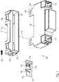
- Figure 1 shows a partly exploded perspective view of an electrical device 100 according to the present invention.
- the electrical device 100 may be any kind of rail mounted electrical device, such as a circuit breaker, fuse unit, safety switching and/or control device, or a rail mounted power supply. Because the electric functionality is not important for the mechanical principle of the present invention, no further details on the electronic components are shown in the drawings. For instance, one or more connector receptacles 110 may be provided for connecting external electrical components to the electrical device 100.
- an electrically insulating housing of the electrical device 100 comprises a bottom shell 102 and a cover 104.
- the cover 104 is fixed on the bottom shell 102 by means of four snap hooks 106 which engage with corresponding recesses 108 in order to form a closed protective housing.
- the housing may also be formed from a single part or from more than two parts.
- the bottom shell 102 and the cover 104 advantageously are fabricated from an electrically insulating plastic material.
- the bottom shell 102 is formed to grip a rail (not shown in the Figures) within a rail recess 112.
- the bottom shell 102 is adapted to be mounted on a so-called DIN rail (also known as top hat rail according to the European standard EN 50022, in the USA called TS35 rail).
- DIN rail also known as top hat rail according to the European standard EN 50022, in the USA called TS35 rail.
- TS35 rail so-called DIN rail
- the mounting technique according to the present invention can of course also be employed with any other cross-sectional form of a mounting rail.
- the rail recess 112 comprises two opposing rail gripping projections 116, at least one of which is movable in a direction across to a longitudinal axis 114 of the rail for mounting and dismounting the electrical device to/from the rail.
- at least one of the rail gripping projections 116 is an integral part of a latch member 118.
- the latch member 118 is held slidably within the bottom shell 102.
- the latch member 118 has an actuating region 122 which passes through an actuating opening 124 provided at the bottom shell 102.
- the actuating region 122 In the fully locked state, the actuating region 122 is received within the actuating opening 124 and the outer surface 126 of the actuating region is flush with the outer surface 128 of the bottom shell 102. In the unlocked state, the actuating region 122 extends outside the actuating opening 124 and is accessible for an operator. In this position, a flat torsion spring 130 is compressed in order to resiliently bias the latch member 118 to automatically move in the direction 120 when released.
- the latch member 118 is secured in the locked as well as the unlocked position by means of a snap fit between the latch member 118 and the bottom shell 102.
- the latch member comprises a resilient catch arm 132.
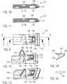
- Fig. 2 shows a schematic sectional view of the bottom shell 102 with two latch members 118 each in a locked position, where the rail gripping projections 116 grip the DIN rail. In this position, the surface is 126 and 128 are flush, so that the latch member 118 is safely stored inside the housing.
- the torsion spring 130 has a first leg 134 and a second leg 136 which are connected to each other via a hinge region 138. The first leg 134 rests against a retention pin 140 which is arranged at that part of the housing which is cut away in the view of Figures 2 and 3 and extends towards the latch member 118. The second leg 136 in held within a groove 142 provided at the latch member 118.
- the retention pin 140 holds back the first leg 134 so that the torsion spring 130 is compressed to include a smaller angle between the first leg 134 and the second leg 136. Thereby energy is stored in the torsion spring 130 that will cause the latch member 118 to move back into the locked position when it is not actively restrained in the unlocked position.
- the bottom shell 102 further comprises stop angles 144 that limit the movement of the latch member 118 in the direction 121 to a distance X. Consequently, the retention pin 140 also deflects the first leg 134 of the torsion spring 130 by a maximum distance of X when the latch member 118 is slid from the locked into the unlocked position.
- the spring 130 is deformed, the second leg 136 is fixed in the groove 142 and additionally rests against a support wall 146. Thereby it can be ensured that the torsion spring biases the latch member 118 with a uniformly distributed force (directed in the direction 120) across the latch member's complete breadth for allowing a smooth sliding movement back into the locked position.
- Fig. 4 shows a top view of the bottom shell shown in Fig. 2 .
- Figures 5 and 6 are sectional views along the lines A-A and B-B of Fig. 4 , respectively.
- two latch members 118 can be inserted into latch member receptacles 148.
- the latch member receptacles 148 are not formed symmetrical to each other, but are formed identical and turned by 180°.
- Figures 7 and 8 show as enlarged details a first snap recess 150 and a second snap recess 152 formed at the housing for retaining the latch member 118 in the locked position and the unlocked position, respectively.
- the first and second snap recesses 150, 152 engage with a detent lug formed at the catch arm 132 of the latch member 118.
- the bottom shell 102 comprises an opening 154.
- the opening 154 preferably only gives access for a suitable tool, for instance a screw driver or the like, so that unintentional releasing of the latch member 118 can be avoided.
- Figures 9 to 11 show different views of the latch member 118 which is fabricated as a part separate from the housing.
- one end of the latch member 118 is formed as a rail gripping projection 116 which in the locked state of the latch member 118 grips behind the edge of a top hat rail as this is known to a person skilled in the art.
- the opposing end of the latch member 118 is formed as an actuating region 122 for pushing the latch member 118 from the outside into the housing (as will be explained in more detail below).
- the latch member 118 For securing the latch member 118 in the locked as well as in the unlocked state, the latch member 118 comprises a resilient catch arm 132.
- the catch arm 132 has a detent lug 156 that engages with either the first snap recess 150 or with the second snap recess 152 of the bottom shell 102 for fixing the latch member 118 in a fully inserted locking position or a partly extracted unlocked position, respectively.
- the catch arm For actuating the catch arm through the opening 154, the catch arm has an essentially planar actuating section 158.
- Stop edges 160 that are provided close to the rail gripping projection 116 interact with the stop angles 144 in order to prevent the latch member 118 to be pushed outside too far when being moved into the unlocked position.
- the latch member 118 is embedded in a depression 162 that essentially follows the outer contour of the torsion spring 130 in a relaxed or only slightly compressed state.
- a support wall 146 is formed that experiences an evenly distributed pressure force exerted by the second leg 136 of the torsion spring 130 when in a compressed state.
- a groove 142 is formed which firmly holds the end of the second leg 136.
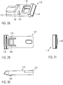
- Fig. 12 and 13 show the mounting are the slack torsion spring 130 inside the depression 162.
- the flat torsion spring 130 may be slightly compressed in the state shown in Fig. 13 , so that both legs are resting against the walls of the depression 162.
- the outer end of the second lead 136 is firmly held in the groove 142.
- the first leg 134 is movable towards the second leg 136.
- the peripheral end of the first leg 134 is accessible for engaging with the retention pin 140 that is provided at the bottom shell 102 of the housing.
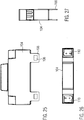
- the torsion spring 130 is depicted in Figures 14 and 15 .
- the torsion spring 130 is a flat spring that is formed from a cut and bent metal sheet. It is clear for a person skilled in the art, that of course also a wire spring, advantageously with some coil windings in the hinge region 138, can be provided.
- Fig. 14 shows the flat torsion spring 130 in its tension free state.
- the angle ⁇ between the first and second legs 134, 136 is approximately 30°.
- other angles ⁇ can be chosen according to the actual required displacement distances X.
- Figures 16 to 18 refer to the latch members 118 being in a locked position ("Position 1"), where the electric device 100 is firmly attached to the rail.
- Figures 19 to 21 show the completely unlocked position (“Position 2"), where both latch members 118 are retracted from the rail so that the electrical device 100 and can be removed from the rail.
- Position 2 the completely unlocked position
- both latch members 118 are pushed towards the rail recess 112 so that a DIN rail can be firmly gripped by the rail gripping projections 116.
- the actuating regions 122 are completely within the bottom shell 102.
- the underlying catch arm 132 can be actuated and the latch member 118 can accordingly be moved into Position 2 (shown in Figures 19 to 21 ). In this position, the actuating region 122 is accessible from the outside.
- the detent lug 156 is held (with only a low force) in the second snap recess 152.
- the latch member 118 is biased against the housing by means of the compressed torsion spring 130 when the latch member 118 is in the unlocked state.
- the bottom shell 102 comprises two opposing latch members 118, so that two movable rail gripping projections 116 are extending into the rail recess 112.
- Figures 22 to 24 show a further embodiment of the present invention, where the bottom shell 102 comprises only one latch member receptacle 148 according to the principles of the present invention.
- the bottom shell 102 according to the present invention comprises a fixed rail gripping hook 164.
- a cover 104 as shown in Fig. 25 to 26 can be clicked on to the bottom shell 102 to form a closed electrically insulating housing.
- the electrically insulating housing may of course also be formed from one integral part or from more than two parts.
- the cover is fixed by resilient flaps 166 having recesses 108 for the snap hooks 106.
- apart from a snap fixed connection also laser welding or gluing or any other suitable connection technique can be employed.
- the latch member 118 is not snap fixed in the open position, but needs to be held back by gripping a recess 172 for instance by means of a suitable tool.
- REFERENCE NUMERALS Reference Numeral Description 100 Electrical device 102 Bottom shell 104 Cover 106 Snap hook 108 Recess for snap hook 110 Connector receptacle 112 Rail recess 114 Longitudinal axis of the rail 116 Rail gripping projection 118 Latch member 120 Direction into locked position (towards middle axis of the rail) 121 Direction into unlocked position (away from middle axis of the rail) 122 Actuating region at the latch member 124 Actuating opening at the housing 126 Outer surface of actuating region 128 Outer surface of bottom shell 130 Flat torsion spring 132 Catch arm 134 First leg 136 Second leg 138 Hinge region 140 Retention pin 142 Groove at the latch member 144 Stop angle 146 Support wall 148 Latch member receptacle 150 First snap recess at housing 152 Second snap
Landscapes
- Engineering & Computer Science (AREA)
- Power Engineering (AREA)
- Microelectronics & Electronic Packaging (AREA)
- Mounting Components In General For Electric Apparatus (AREA)
- Casings For Electric Apparatus (AREA)
Priority Applications (3)
| Application Number | Priority Date | Filing Date | Title |
|---|---|---|---|
| EP16155836.6A EP3208900B1 (de) | 2016-02-16 | 2016-02-16 | Elektrische vorrichtung für schienenmontage |
| CN201710304089.4A CN107104366A (zh) | 2016-02-16 | 2017-02-16 | 用于轨道安装的电气设备 |
| US15/434,955 US10390449B2 (en) | 2016-02-16 | 2017-02-16 | Electrical device for rail mounting |
Applications Claiming Priority (1)
| Application Number | Priority Date | Filing Date | Title |
|---|---|---|---|
| EP16155836.6A EP3208900B1 (de) | 2016-02-16 | 2016-02-16 | Elektrische vorrichtung für schienenmontage |
Publications (2)
| Publication Number | Publication Date |
|---|---|
| EP3208900A1 true EP3208900A1 (de) | 2017-08-23 |
| EP3208900B1 EP3208900B1 (de) | 2020-04-29 |
Family
ID=55405144
Family Applications (1)
| Application Number | Title | Priority Date | Filing Date |
|---|---|---|---|
| EP16155836.6A Active EP3208900B1 (de) | 2016-02-16 | 2016-02-16 | Elektrische vorrichtung für schienenmontage |
Country Status (3)
| Country | Link |
|---|---|
| US (1) | US10390449B2 (de) |
| EP (1) | EP3208900B1 (de) |
| CN (1) | CN107104366A (de) |
Families Citing this family (8)
| Publication number | Priority date | Publication date | Assignee | Title |
|---|---|---|---|---|
| DE102016203700A1 (de) * | 2016-03-07 | 2017-09-07 | Te Connectivity Germany Gmbh | Schienenbefestigungssystem mit Systemkopplung |
| CN109195399B (zh) * | 2018-10-08 | 2024-05-03 | 珠海格力电器股份有限公司 | 导轨安装结构及控制器 |
| US10687433B1 (en) | 2019-06-12 | 2020-06-16 | Phoenix Contact Development and Manufacturing, Inc. | Electrical component enclosure assembly and method of use |
| DE102019214751A1 (de) * | 2019-09-26 | 2021-04-01 | Mahle International Gmbh | Gehäuse |
| CN112576869A (zh) * | 2019-09-27 | 2021-03-30 | 台达电子工业股份有限公司 | 电源模块 |
| US11576275B2 (en) * | 2021-02-26 | 2023-02-07 | Adlink Technology Inc. | DIN rail installation kit and its operation method |
| US12107377B2 (en) | 2021-09-14 | 2024-10-01 | Appleton Grp Llc | Plastic latching system for securement of electronic component to a DIN rail |
| EP4242903B1 (de) * | 2022-03-11 | 2025-10-22 | Suprema Inc. | Endgerätevorrichtungsanordnung und endgeräteausrüstung damit |
Citations (6)
| Publication number | Priority date | Publication date | Assignee | Title |
|---|---|---|---|---|
| DE1162443B (de) * | 1962-07-26 | 1964-02-06 | Siemens Ag | Anordnung zur Befestigung elektrischer Installationsgeraete, insbesondere Leitungsschutzschalter |
| DE1174873B (de) * | 1962-07-26 | 1964-07-30 | Siemens Ag | Befestigungsanordnung fuer elektrische Installationsgeraete, insbesondere Leitungs-schutzschalter |
| FR2432258A1 (fr) * | 1978-07-28 | 1980-02-22 | Legrand Sa | Appareil electrique a fixer sur un rail ou profile a ailes symetriques |
| EP0184143A2 (de) * | 1984-11-29 | 1986-06-11 | Christian Geyer GmbH & Co. | Vorrichtung zur Befestigung eines elektrischen Schaltgerätes |
| GB2216177A (en) | 1988-02-27 | 1989-10-04 | Delta Circuits Protection | Electrical device for rail mounting |
| EP2677846A1 (de) * | 2011-02-17 | 2013-12-25 | Kabushiki Kaisha Yaskawa Denki | Vorrichtung zur befestigung auf din-schienen |
Family Cites Families (12)
| Publication number | Priority date | Publication date | Assignee | Title |
|---|---|---|---|---|
| US5761026A (en) * | 1996-04-02 | 1998-06-02 | Square D Company | Snap-on circuit breaker mounting system |
| US5904592A (en) * | 1998-09-29 | 1999-05-18 | Allen-Bradley Company, Llc | Dual mode din rail latch with tactile feedback |
| US6292076B1 (en) * | 1999-08-30 | 2001-09-18 | Eaton Corporation | Circuit interrupter with improved DIN rail mounting adaptor |
| FR2798813B1 (fr) * | 1999-09-16 | 2001-10-12 | Entrelec Sa | Dispositif de connexion electrique comportant un pied de fixation sur un rail support |
| JP3759063B2 (ja) * | 2002-04-02 | 2006-03-22 | 理化工業株式会社 | 電子機器の取付構造 |
| DE102006049019B4 (de) * | 2006-10-13 | 2009-11-26 | Phoenix Contact Gmbh & Co. Kg | Montageplatte mit Befestigungsmitteln für ein elektrisches Gerät |
| CN101754633B (zh) * | 2008-12-09 | 2011-12-14 | 四零四科技股份有限公司 | 适用于嵌入式轨道的夹持装置 |
| FR2958788B1 (fr) * | 2010-04-09 | 2015-01-30 | Abb France | Varistance comprenant une electrode avec une partie en saillie formant pole et parafoudre comprenant une telle varistance |
| US8226433B1 (en) * | 2011-03-23 | 2012-07-24 | Phoenix Contact Development & Manufacturing, Inc. | Latch assembly for mounting power supply base for a process fieldbus on a DIN rail and method |
| GB2521445A (en) * | 2013-12-20 | 2015-06-24 | Control Tech Ltd | Mounting Latch |
| CN204031683U (zh) * | 2014-07-16 | 2014-12-17 | 光宝电子(广州)有限公司 | 扣合装置 |
| US9374924B2 (en) * | 2014-09-16 | 2016-06-21 | Schneider Electric Buildings, Llc | DIN rail mounted enclosure assembly and method of use |
-
2016
- 2016-02-16 EP EP16155836.6A patent/EP3208900B1/de active Active
-
2017
- 2017-02-16 US US15/434,955 patent/US10390449B2/en not_active Expired - Fee Related
- 2017-02-16 CN CN201710304089.4A patent/CN107104366A/zh active Pending
Patent Citations (6)
| Publication number | Priority date | Publication date | Assignee | Title |
|---|---|---|---|---|
| DE1162443B (de) * | 1962-07-26 | 1964-02-06 | Siemens Ag | Anordnung zur Befestigung elektrischer Installationsgeraete, insbesondere Leitungsschutzschalter |
| DE1174873B (de) * | 1962-07-26 | 1964-07-30 | Siemens Ag | Befestigungsanordnung fuer elektrische Installationsgeraete, insbesondere Leitungs-schutzschalter |
| FR2432258A1 (fr) * | 1978-07-28 | 1980-02-22 | Legrand Sa | Appareil electrique a fixer sur un rail ou profile a ailes symetriques |
| EP0184143A2 (de) * | 1984-11-29 | 1986-06-11 | Christian Geyer GmbH & Co. | Vorrichtung zur Befestigung eines elektrischen Schaltgerätes |
| GB2216177A (en) | 1988-02-27 | 1989-10-04 | Delta Circuits Protection | Electrical device for rail mounting |
| EP2677846A1 (de) * | 2011-02-17 | 2013-12-25 | Kabushiki Kaisha Yaskawa Denki | Vorrichtung zur befestigung auf din-schienen |
Also Published As
| Publication number | Publication date |
|---|---|
| US10390449B2 (en) | 2019-08-20 |
| CN107104366A (zh) | 2017-08-29 |
| US20170238433A1 (en) | 2017-08-17 |
| EP3208900B1 (de) | 2020-04-29 |
Similar Documents
| Publication | Publication Date | Title |
|---|---|---|
| US10390449B2 (en) | Electrical device for rail mounting | |
| US20150102608A1 (en) | Door interlock device for transformer room of vacuum circuit breaker | |
| EP2899813B1 (de) | Steckverbinder | |
| US9806462B2 (en) | Electrical connection terminal having an insert device for providing a counter-bearing for a tool | |
| GB2370432A (en) | Modular fuse holder with fuse drawer | |
| CN105580204A (zh) | 贯穿式端子和电气装置 | |
| WO2015083140A1 (en) | Terminal position assurance member, terminal assembly, connector housing assembly and connector | |
| CN111064017B (zh) | 保护导体端子 | |
| JP6280816B2 (ja) | 電線固定具 | |
| JP5884078B2 (ja) | 電線接続端子及びそれを備えた配線器具 | |
| US9270033B2 (en) | Lug retention arrangement | |
| MXPA02010306A (es) | Barrera para dedos para interruptores de energia electrica e interruptor de energia electrica que lo incorpora. | |
| US9741500B1 (en) | Terminal connecting mechanism for molded case circuit breaker | |
| US20030194887A1 (en) | Connector for electric apparatus | |
| HK1242052A (en) | Electrical device for rail mounting | |
| HK1242052A1 (en) | Electrical device for rail mounting | |
| KR20210123397A (ko) | 보호 도체 연결부 | |
| JP2875750B2 (ja) | レール取付装置 | |
| US11217926B2 (en) | Contact element having a contact body and a spring element arranged thereon | |
| CN109314354B (zh) | 穿引端子 | |
| US20160359272A1 (en) | Enclosure Assembly for an Electrical Connector and Same | |
| JPS5935490B2 (ja) | 電けん操作用延長形押し棒 | |
| JPH0311820Y2 (de) | ||
| JP2011231835A (ja) | 溝付棒状部材用のクランプ及びワイヤーハーネス用プロテクタ | |
| JP4901277B2 (ja) | 閉塞具 |
Legal Events
| Date | Code | Title | Description |
|---|---|---|---|
| PUAI | Public reference made under article 153(3) epc to a published international application that has entered the european phase |
Free format text: ORIGINAL CODE: 0009012 |
|
| STAA | Information on the status of an ep patent application or granted ep patent |
Free format text: STATUS: THE APPLICATION HAS BEEN PUBLISHED |
|
| AK | Designated contracting states |
Kind code of ref document: A1 Designated state(s): AL AT BE BG CH CY CZ DE DK EE ES FI FR GB GR HR HU IE IS IT LI LT LU LV MC MK MT NL NO PL PT RO RS SE SI SK SM TR |
|
| AX | Request for extension of the european patent |
Extension state: BA ME |
|
| STAA | Information on the status of an ep patent application or granted ep patent |
Free format text: STATUS: REQUEST FOR EXAMINATION WAS MADE |
|
| 17P | Request for examination filed |
Effective date: 20180215 |
|
| RBV | Designated contracting states (corrected) |
Designated state(s): AL AT BE BG CH CY CZ DE DK EE ES FI FR GB GR HR HU IE IS IT LI LT LU LV MC MK MT NL NO PL PT RO RS SE SI SK SM TR |
|
| REG | Reference to a national code |
Ref country code: HK Ref legal event code: DE Ref document number: 1242052 Country of ref document: HK |
|
| GRAP | Despatch of communication of intention to grant a patent |
Free format text: ORIGINAL CODE: EPIDOSNIGR1 |
|
| STAA | Information on the status of an ep patent application or granted ep patent |
Free format text: STATUS: GRANT OF PATENT IS INTENDED |
|
| RIC1 | Information provided on ipc code assigned before grant |
Ipc: H02B 1/052 20060101AFI20191101BHEP |
|
| INTG | Intention to grant announced |
Effective date: 20191127 |
|
| GRAS | Grant fee paid |
Free format text: ORIGINAL CODE: EPIDOSNIGR3 |
|
| GRAA | (expected) grant |
Free format text: ORIGINAL CODE: 0009210 |
|
| STAA | Information on the status of an ep patent application or granted ep patent |
Free format text: STATUS: THE PATENT HAS BEEN GRANTED |
|
| AK | Designated contracting states |
Kind code of ref document: B1 Designated state(s): AL AT BE BG CH CY CZ DE DK EE ES FI FR GB GR HR HU IE IS IT LI LT LU LV MC MK MT NL NO PL PT RO RS SE SI SK SM TR |
|
| REG | Reference to a national code |
Ref country code: GB Ref legal event code: FG4D |
|
| REG | Reference to a national code |
Ref country code: CH Ref legal event code: EP |
|
| REG | Reference to a national code |
Ref country code: AT Ref legal event code: REF Ref document number: 1264724 Country of ref document: AT Kind code of ref document: T Effective date: 20200515 |
|
| REG | Reference to a national code |
Ref country code: DE Ref legal event code: R096 Ref document number: 602016034868 Country of ref document: DE |
|
| REG | Reference to a national code |
Ref country code: IE Ref legal event code: FG4D |
|
| REG | Reference to a national code |
Ref country code: NL Ref legal event code: MP Effective date: 20200429 |
|
| REG | Reference to a national code |
Ref country code: LT Ref legal event code: MG4D |
|
| PG25 | Lapsed in a contracting state [announced via postgrant information from national office to epo] |
Ref country code: PT Free format text: LAPSE BECAUSE OF FAILURE TO SUBMIT A TRANSLATION OF THE DESCRIPTION OR TO PAY THE FEE WITHIN THE PRESCRIBED TIME-LIMIT Effective date: 20200831 Ref country code: IS Free format text: LAPSE BECAUSE OF FAILURE TO SUBMIT A TRANSLATION OF THE DESCRIPTION OR TO PAY THE FEE WITHIN THE PRESCRIBED TIME-LIMIT Effective date: 20200829 Ref country code: SE Free format text: LAPSE BECAUSE OF FAILURE TO SUBMIT A TRANSLATION OF THE DESCRIPTION OR TO PAY THE FEE WITHIN THE PRESCRIBED TIME-LIMIT Effective date: 20200429 Ref country code: GR Free format text: LAPSE BECAUSE OF FAILURE TO SUBMIT A TRANSLATION OF THE DESCRIPTION OR TO PAY THE FEE WITHIN THE PRESCRIBED TIME-LIMIT Effective date: 20200730 Ref country code: LT Free format text: LAPSE BECAUSE OF FAILURE TO SUBMIT A TRANSLATION OF THE DESCRIPTION OR TO PAY THE FEE WITHIN THE PRESCRIBED TIME-LIMIT Effective date: 20200429 Ref country code: FI Free format text: LAPSE BECAUSE OF FAILURE TO SUBMIT A TRANSLATION OF THE DESCRIPTION OR TO PAY THE FEE WITHIN THE PRESCRIBED TIME-LIMIT Effective date: 20200429 Ref country code: NO Free format text: LAPSE BECAUSE OF FAILURE TO SUBMIT A TRANSLATION OF THE DESCRIPTION OR TO PAY THE FEE WITHIN THE PRESCRIBED TIME-LIMIT Effective date: 20200729 |
|
| REG | Reference to a national code |
Ref country code: AT Ref legal event code: MK05 Ref document number: 1264724 Country of ref document: AT Kind code of ref document: T Effective date: 20200429 |
|
| PG25 | Lapsed in a contracting state [announced via postgrant information from national office to epo] |
Ref country code: HR Free format text: LAPSE BECAUSE OF FAILURE TO SUBMIT A TRANSLATION OF THE DESCRIPTION OR TO PAY THE FEE WITHIN THE PRESCRIBED TIME-LIMIT Effective date: 20200429 Ref country code: LV Free format text: LAPSE BECAUSE OF FAILURE TO SUBMIT A TRANSLATION OF THE DESCRIPTION OR TO PAY THE FEE WITHIN THE PRESCRIBED TIME-LIMIT Effective date: 20200429 Ref country code: BG Free format text: LAPSE BECAUSE OF FAILURE TO SUBMIT A TRANSLATION OF THE DESCRIPTION OR TO PAY THE FEE WITHIN THE PRESCRIBED TIME-LIMIT Effective date: 20200729 Ref country code: RS Free format text: LAPSE BECAUSE OF FAILURE TO SUBMIT A TRANSLATION OF THE DESCRIPTION OR TO PAY THE FEE WITHIN THE PRESCRIBED TIME-LIMIT Effective date: 20200429 |
|
| PG25 | Lapsed in a contracting state [announced via postgrant information from national office to epo] |
Ref country code: NL Free format text: LAPSE BECAUSE OF FAILURE TO SUBMIT A TRANSLATION OF THE DESCRIPTION OR TO PAY THE FEE WITHIN THE PRESCRIBED TIME-LIMIT Effective date: 20200429 Ref country code: AL Free format text: LAPSE BECAUSE OF FAILURE TO SUBMIT A TRANSLATION OF THE DESCRIPTION OR TO PAY THE FEE WITHIN THE PRESCRIBED TIME-LIMIT Effective date: 20200429 |
|
| PG25 | Lapsed in a contracting state [announced via postgrant information from national office to epo] |
Ref country code: DK Free format text: LAPSE BECAUSE OF FAILURE TO SUBMIT A TRANSLATION OF THE DESCRIPTION OR TO PAY THE FEE WITHIN THE PRESCRIBED TIME-LIMIT Effective date: 20200429 Ref country code: EE Free format text: LAPSE BECAUSE OF FAILURE TO SUBMIT A TRANSLATION OF THE DESCRIPTION OR TO PAY THE FEE WITHIN THE PRESCRIBED TIME-LIMIT Effective date: 20200429 Ref country code: SM Free format text: LAPSE BECAUSE OF FAILURE TO SUBMIT A TRANSLATION OF THE DESCRIPTION OR TO PAY THE FEE WITHIN THE PRESCRIBED TIME-LIMIT Effective date: 20200429 Ref country code: IT Free format text: LAPSE BECAUSE OF FAILURE TO SUBMIT A TRANSLATION OF THE DESCRIPTION OR TO PAY THE FEE WITHIN THE PRESCRIBED TIME-LIMIT Effective date: 20200429 Ref country code: RO Free format text: LAPSE BECAUSE OF FAILURE TO SUBMIT A TRANSLATION OF THE DESCRIPTION OR TO PAY THE FEE WITHIN THE PRESCRIBED TIME-LIMIT Effective date: 20200429 Ref country code: CZ Free format text: LAPSE BECAUSE OF FAILURE TO SUBMIT A TRANSLATION OF THE DESCRIPTION OR TO PAY THE FEE WITHIN THE PRESCRIBED TIME-LIMIT Effective date: 20200429 Ref country code: AT Free format text: LAPSE BECAUSE OF FAILURE TO SUBMIT A TRANSLATION OF THE DESCRIPTION OR TO PAY THE FEE WITHIN THE PRESCRIBED TIME-LIMIT Effective date: 20200429 Ref country code: ES Free format text: LAPSE BECAUSE OF FAILURE TO SUBMIT A TRANSLATION OF THE DESCRIPTION OR TO PAY THE FEE WITHIN THE PRESCRIBED TIME-LIMIT Effective date: 20200429 |
|
| REG | Reference to a national code |
Ref country code: DE Ref legal event code: R097 Ref document number: 602016034868 Country of ref document: DE |
|
| PG25 | Lapsed in a contracting state [announced via postgrant information from national office to epo] |
Ref country code: PL Free format text: LAPSE BECAUSE OF FAILURE TO SUBMIT A TRANSLATION OF THE DESCRIPTION OR TO PAY THE FEE WITHIN THE PRESCRIBED TIME-LIMIT Effective date: 20200429 Ref country code: SK Free format text: LAPSE BECAUSE OF FAILURE TO SUBMIT A TRANSLATION OF THE DESCRIPTION OR TO PAY THE FEE WITHIN THE PRESCRIBED TIME-LIMIT Effective date: 20200429 |
|
| PLBE | No opposition filed within time limit |
Free format text: ORIGINAL CODE: 0009261 |
|
| STAA | Information on the status of an ep patent application or granted ep patent |
Free format text: STATUS: NO OPPOSITION FILED WITHIN TIME LIMIT |
|
| 26N | No opposition filed |
Effective date: 20210201 |
|
| PG25 | Lapsed in a contracting state [announced via postgrant information from national office to epo] |
Ref country code: SI Free format text: LAPSE BECAUSE OF FAILURE TO SUBMIT A TRANSLATION OF THE DESCRIPTION OR TO PAY THE FEE WITHIN THE PRESCRIBED TIME-LIMIT Effective date: 20200429 |
|
| PG25 | Lapsed in a contracting state [announced via postgrant information from national office to epo] |
Ref country code: MC Free format text: LAPSE BECAUSE OF FAILURE TO SUBMIT A TRANSLATION OF THE DESCRIPTION OR TO PAY THE FEE WITHIN THE PRESCRIBED TIME-LIMIT Effective date: 20200429 |
|
| GBPC | Gb: european patent ceased through non-payment of renewal fee |
Effective date: 20210216 |
|
| REG | Reference to a national code |
Ref country code: BE Ref legal event code: MM Effective date: 20210228 |
|
| PG25 | Lapsed in a contracting state [announced via postgrant information from national office to epo] |
Ref country code: LI Free format text: LAPSE BECAUSE OF NON-PAYMENT OF DUE FEES Effective date: 20210228 Ref country code: LU Free format text: LAPSE BECAUSE OF NON-PAYMENT OF DUE FEES Effective date: 20210216 Ref country code: CH Free format text: LAPSE BECAUSE OF NON-PAYMENT OF DUE FEES Effective date: 20210228 |
|
| PG25 | Lapsed in a contracting state [announced via postgrant information from national office to epo] |
Ref country code: FR Free format text: LAPSE BECAUSE OF NON-PAYMENT OF DUE FEES Effective date: 20210228 Ref country code: IE Free format text: LAPSE BECAUSE OF NON-PAYMENT OF DUE FEES Effective date: 20210216 Ref country code: GB Free format text: LAPSE BECAUSE OF NON-PAYMENT OF DUE FEES Effective date: 20210216 |
|
| PG25 | Lapsed in a contracting state [announced via postgrant information from national office to epo] |
Ref country code: BE Free format text: LAPSE BECAUSE OF NON-PAYMENT OF DUE FEES Effective date: 20210228 |
|
| PG25 | Lapsed in a contracting state [announced via postgrant information from national office to epo] |
Ref country code: HU Free format text: LAPSE BECAUSE OF FAILURE TO SUBMIT A TRANSLATION OF THE DESCRIPTION OR TO PAY THE FEE WITHIN THE PRESCRIBED TIME-LIMIT; INVALID AB INITIO Effective date: 20160216 |
|
| PG25 | Lapsed in a contracting state [announced via postgrant information from national office to epo] |
Ref country code: CY Free format text: LAPSE BECAUSE OF FAILURE TO SUBMIT A TRANSLATION OF THE DESCRIPTION OR TO PAY THE FEE WITHIN THE PRESCRIBED TIME-LIMIT Effective date: 20200429 |
|
| PG25 | Lapsed in a contracting state [announced via postgrant information from national office to epo] |
Ref country code: MK Free format text: LAPSE BECAUSE OF FAILURE TO SUBMIT A TRANSLATION OF THE DESCRIPTION OR TO PAY THE FEE WITHIN THE PRESCRIBED TIME-LIMIT Effective date: 20200429 |
|
| PG25 | Lapsed in a contracting state [announced via postgrant information from national office to epo] |
Ref country code: TR Free format text: LAPSE BECAUSE OF FAILURE TO SUBMIT A TRANSLATION OF THE DESCRIPTION OR TO PAY THE FEE WITHIN THE PRESCRIBED TIME-LIMIT Effective date: 20200429 |
|
| REG | Reference to a national code |
Ref country code: HK Ref legal event code: WD Ref document number: 1242052 Country of ref document: HK |
|
| PG25 | Lapsed in a contracting state [announced via postgrant information from national office to epo] |
Ref country code: MT Free format text: LAPSE BECAUSE OF FAILURE TO SUBMIT A TRANSLATION OF THE DESCRIPTION OR TO PAY THE FEE WITHIN THE PRESCRIBED TIME-LIMIT Effective date: 20200429 |
|
| PGFP | Annual fee paid to national office [announced via postgrant information from national office to epo] |
Ref country code: DE Payment date: 20250225 Year of fee payment: 10 |