EP3208931A1 - Dispositif de conversion de puissance triphasé bloqué au point neutre - Google Patents
Dispositif de conversion de puissance triphasé bloqué au point neutre Download PDFInfo
- Publication number
- EP3208931A1 EP3208931A1 EP15852818.2A EP15852818A EP3208931A1 EP 3208931 A1 EP3208931 A1 EP 3208931A1 EP 15852818 A EP15852818 A EP 15852818A EP 3208931 A1 EP3208931 A1 EP 3208931A1
- Authority
- EP
- European Patent Office
- Prior art keywords
- phase
- current
- command voltage
- neutral point
- axis
- Prior art date
- Legal status (The legal status is an assumption and is not a legal conclusion. Google has not performed a legal analysis and makes no representation as to the accuracy of the status listed.)
- Ceased
Links
Images


Classifications
-
- H—ELECTRICITY
- H02—GENERATION; CONVERSION OR DISTRIBUTION OF ELECTRIC POWER
- H02M—APPARATUS FOR CONVERSION BETWEEN AC AND AC, BETWEEN AC AND DC, OR BETWEEN DC AND DC, AND FOR USE WITH MAINS OR SIMILAR POWER SUPPLY SYSTEMS; CONVERSION OF DC OR AC INPUT POWER INTO SURGE OUTPUT POWER; CONTROL OR REGULATION THEREOF
- H02M7/00—Conversion of AC power input into DC power output; Conversion of DC power input into AC power output
- H02M7/42—Conversion of DC power input into AC power output without possibility of reversal
- H02M7/44—Conversion of DC power input into AC power output without possibility of reversal by static converters
- H02M7/48—Conversion of DC power input into AC power output without possibility of reversal by static converters using discharge tubes with control electrode or semiconductor devices with control electrode
-
- H—ELECTRICITY
- H02—GENERATION; CONVERSION OR DISTRIBUTION OF ELECTRIC POWER
- H02P—CONTROL OR REGULATION OF ELECTRIC MOTORS, ELECTRIC GENERATORS OR DYNAMO-ELECTRIC CONVERTERS; CONTROLLING TRANSFORMERS, REACTORS OR CHOKE COILS
- H02P21/00—Arrangements or methods for the control of electric machines by vector control, e.g. by control of field orientation
- H02P21/14—Estimation or adaptation of machine parameters, e.g. flux, current or voltage
-
- H—ELECTRICITY
- H02—GENERATION; CONVERSION OR DISTRIBUTION OF ELECTRIC POWER
- H02M—APPARATUS FOR CONVERSION BETWEEN AC AND AC, BETWEEN AC AND DC, OR BETWEEN DC AND DC, AND FOR USE WITH MAINS OR SIMILAR POWER SUPPLY SYSTEMS; CONVERSION OF DC OR AC INPUT POWER INTO SURGE OUTPUT POWER; CONTROL OR REGULATION THEREOF
- H02M1/00—Details of apparatus for conversion
- H02M1/08—Circuits specially adapted for the generation of control voltages for semiconductor devices incorporated in static converters
-
- H—ELECTRICITY
- H02—GENERATION; CONVERSION OR DISTRIBUTION OF ELECTRIC POWER
- H02M—APPARATUS FOR CONVERSION BETWEEN AC AND AC, BETWEEN AC AND DC, OR BETWEEN DC AND DC, AND FOR USE WITH MAINS OR SIMILAR POWER SUPPLY SYSTEMS; CONVERSION OF DC OR AC INPUT POWER INTO SURGE OUTPUT POWER; CONTROL OR REGULATION THEREOF
- H02M5/00—Conversion of AC power input into AC power output, e.g. for change of voltage, for change of frequency, for change of number of phases
- H02M5/40—Conversion of AC power input into AC power output, e.g. for change of voltage, for change of frequency, for change of number of phases with intermediate conversion into DC
- H02M5/42—Conversion of AC power input into AC power output, e.g. for change of voltage, for change of frequency, for change of number of phases with intermediate conversion into DC by static converters
- H02M5/44—Conversion of AC power input into AC power output, e.g. for change of voltage, for change of frequency, for change of number of phases with intermediate conversion into DC by static converters using discharge tubes or semiconductor devices to convert the intermediate DC into AC
- H02M5/453—Conversion of AC power input into AC power output, e.g. for change of voltage, for change of frequency, for change of number of phases with intermediate conversion into DC by static converters using discharge tubes or semiconductor devices to convert the intermediate DC into AC using devices of a triode or transistor type requiring continuous application of a control signal
- H02M5/458—Conversion of AC power input into AC power output, e.g. for change of voltage, for change of frequency, for change of number of phases with intermediate conversion into DC by static converters using discharge tubes or semiconductor devices to convert the intermediate DC into AC using devices of a triode or transistor type requiring continuous application of a control signal using semiconductor devices only
- H02M5/4585—Conversion of AC power input into AC power output, e.g. for change of voltage, for change of frequency, for change of number of phases with intermediate conversion into DC by static converters using discharge tubes or semiconductor devices to convert the intermediate DC into AC using devices of a triode or transistor type requiring continuous application of a control signal using semiconductor devices only having a rectifier with controlled elements
-
- H—ELECTRICITY
- H02—GENERATION; CONVERSION OR DISTRIBUTION OF ELECTRIC POWER
- H02M—APPARATUS FOR CONVERSION BETWEEN AC AND AC, BETWEEN AC AND DC, OR BETWEEN DC AND DC, AND FOR USE WITH MAINS OR SIMILAR POWER SUPPLY SYSTEMS; CONVERSION OF DC OR AC INPUT POWER INTO SURGE OUTPUT POWER; CONTROL OR REGULATION THEREOF
- H02M7/00—Conversion of AC power input into DC power output; Conversion of DC power input into AC power output
- H02M7/42—Conversion of DC power input into AC power output without possibility of reversal
- H02M7/44—Conversion of DC power input into AC power output without possibility of reversal by static converters
- H02M7/48—Conversion of DC power input into AC power output without possibility of reversal by static converters using discharge tubes with control electrode or semiconductor devices with control electrode
- H02M7/483—Converters with outputs that each can have more than two voltages levels
- H02M7/4833—Capacitor voltage balancing
-
- H—ELECTRICITY
- H02—GENERATION; CONVERSION OR DISTRIBUTION OF ELECTRIC POWER
- H02M—APPARATUS FOR CONVERSION BETWEEN AC AND AC, BETWEEN AC AND DC, OR BETWEEN DC AND DC, AND FOR USE WITH MAINS OR SIMILAR POWER SUPPLY SYSTEMS; CONVERSION OF DC OR AC INPUT POWER INTO SURGE OUTPUT POWER; CONTROL OR REGULATION THEREOF
- H02M7/00—Conversion of AC power input into DC power output; Conversion of DC power input into AC power output
- H02M7/42—Conversion of DC power input into AC power output without possibility of reversal
- H02M7/44—Conversion of DC power input into AC power output without possibility of reversal by static converters
- H02M7/48—Conversion of DC power input into AC power output without possibility of reversal by static converters using discharge tubes with control electrode or semiconductor devices with control electrode
- H02M7/483—Converters with outputs that each can have more than two voltages levels
- H02M7/487—Neutral point clamped inverters
-
- H—ELECTRICITY
- H02—GENERATION; CONVERSION OR DISTRIBUTION OF ELECTRIC POWER
- H02P—CONTROL OR REGULATION OF ELECTRIC MOTORS, ELECTRIC GENERATORS OR DYNAMO-ELECTRIC CONVERTERS; CONTROLLING TRANSFORMERS, REACTORS OR CHOKE COILS
- H02P21/00—Arrangements or methods for the control of electric machines by vector control, e.g. by control of field orientation
- H02P21/0003—Control strategies in general, e.g. linear type, e.g. P, PI, PID, using robust control
-
- H—ELECTRICITY
- H02—GENERATION; CONVERSION OR DISTRIBUTION OF ELECTRIC POWER
- H02P—CONTROL OR REGULATION OF ELECTRIC MOTORS, ELECTRIC GENERATORS OR DYNAMO-ELECTRIC CONVERTERS; CONTROLLING TRANSFORMERS, REACTORS OR CHOKE COILS
- H02P21/00—Arrangements or methods for the control of electric machines by vector control, e.g. by control of field orientation
- H02P21/06—Rotor flux based control involving the use of rotor position or rotor speed sensors
-
- H—ELECTRICITY
- H02—GENERATION; CONVERSION OR DISTRIBUTION OF ELECTRIC POWER
- H02P—CONTROL OR REGULATION OF ELECTRIC MOTORS, ELECTRIC GENERATORS OR DYNAMO-ELECTRIC CONVERTERS; CONTROLLING TRANSFORMERS, REACTORS OR CHOKE COILS
- H02P21/00—Arrangements or methods for the control of electric machines by vector control, e.g. by control of field orientation
- H02P21/22—Current control, e.g. using a current control loop
-
- H—ELECTRICITY
- H02—GENERATION; CONVERSION OR DISTRIBUTION OF ELECTRIC POWER
- H02P—CONTROL OR REGULATION OF ELECTRIC MOTORS, ELECTRIC GENERATORS OR DYNAMO-ELECTRIC CONVERTERS; CONTROLLING TRANSFORMERS, REACTORS OR CHOKE COILS
- H02P27/00—Arrangements or methods for the control of AC motors characterised by the kind of supply voltage
- H02P27/04—Arrangements or methods for the control of AC motors characterised by the kind of supply voltage using variable-frequency supply voltage, e.g. inverter or converter supply voltage
- H02P27/06—Arrangements or methods for the control of AC motors characterised by the kind of supply voltage using variable-frequency supply voltage, e.g. inverter or converter supply voltage using DC to AC converters or inverters
- H02P27/08—Arrangements or methods for the control of AC motors characterised by the kind of supply voltage using variable-frequency supply voltage, e.g. inverter or converter supply voltage using DC to AC converters or inverters with pulse width modulation
- H02P27/14—Arrangements or methods for the control of AC motors characterised by the kind of supply voltage using variable-frequency supply voltage, e.g. inverter or converter supply voltage using DC to AC converters or inverters with pulse width modulation with three or more levels of voltage
Definitions
- the present invention relates to a three-phase neutral point clamped power conversion apparatus and specifically to current control using PWM control.
- FIG. 6 is a block diagram showing a main circuit of a three-phase neutral point clamped power conversion apparatus connected with a load in the form of a motor.
- the power conversion apparatus controls switching devices S1 ⁇ S12 (IGBTs in FIG. 6 ) ON/OFF by inputting gate commands to the switching devices S1 ⁇ S12, and thereby outputs an ac voltage at output terminals U, V and W.
- This power conversion apparatus is arranged to divide a dc voltage P-N by the use of smoothing capacitors Cdc1 and Cdc2, and to produce an output with a PWM (Pulse Width Modulation) of dc potentials P and N and a neutral point potential NP at three levels.
- PWM Pulse Width Modulation
- Patent documents 1 and 2 both employ a neutral point potential control (Neutral Point Control) for suppressing unevenness in the dc voltages Vdc1 and Vdc2 after ACR (current control: Automatic Current Regulator).
- the neutral point potential control is a control to determine a deviation between the dc voltage Vdc1 of smoothing capacitor Cdc1 on the positive side (P side) of the dc voltage P-N and the dc voltage Vdc2 of the smoothing capacitor Cdc2 on the negative side (N side), and to perform a control operation to reduce the deviation toward zero.
- FIG. 7 is a block diagram showing the control circuit of the three-phase neutral point clamped power conversion apparatus.
- a phase detector enc is attached to the motor M and arranged to detect a phase and to provide a detected phase theta_det.
- a three-phase to two-phase converter 1 converts output currents (motor currents) Iu, Iv, Iw by three-phase to two-phase conversion on the basis of the detected phase theta_det, and thereby provides detected d-axis current Id_det and q-axis current Iq_det.
- a current control section 2 performs a PI control to cause the detected d-axis current Id_det and detected q-axis current Iq_det to follow respective target values set equal to a command d-axis current Id_cmd and a command q-axis current Iq_cmd, respectively.
- PI control On the output side of the PI control, there are provided limiters LMT1 and LMT2 for restraining integral outputs at the time of output saturation and thereby stabilizing the system.
- the output of current control section 2 is a two-phase command voltage of Vd_cmd and Vq_cmd.
- the two-phase command voltage Vd_cmd, Vq_cmd is converted, by the two-phase to three-phase conversion with a two-phase to three-phase converter 3, into a three-phase command voltage V_cmd.
- a neutral point potential control section 4 adds a neutral point potential compensation quantity V_cmp to the three-phase command voltage V_cmd, and thereby delivers the command voltage obtained by the addition as a corrected command voltage V_cmd'.
- a limiter LMT3 imposes voltage limitation on the corrected command voltage Vcmd' and supplies a limiter processed command voltage Vcmd" obtained by the voltage limitation, to a PWM process section PWM.
- the limiter LMT3 is provided to prevent later-mentioned gate commands GI_H and GI_L from becoming abnormal pulse (minimal pulse, for example) and to prevent the output voltage and output current of the power conversion apparatus from being distorted.
- the PMW process section PWM produces gate commands GI_H, GI_L for each of switching devices S1 ⁇ S12 by using the limiter processed command voltage Vcmd".
- the gate commands GI_H, GI_L are produced by comparison between a triangular wave carrier signal and the limiter processed command voltage V_cmd", though not shown in FIG. 7 .
- the limiters LMT1 and LMT2 are provided at the output of the PI control for stabilizing the current control, and thereafter the neutral point potential compensation quantity V_cmp is added to the three-phase command voltage V_cmd in the configuration of FIG. 7 .
- the corrected command voltage V_cmd' after the addition is inputted to the limiter LMT3 before the PWM process.
- the limiter processed command voltage V_cmd is subjected to the voltage limitation. Therefore, the effective value of the output voltage of the power conversion apparatus (the voltage between U and V terminals of FIG. 6 , for example) is unable to retain the linearity.
- the time of the voltage limitation becomes long, the effective value of the output current of the power conversion apparatus too loses the linearity and the operation becomes unstable.
- the current control includes the integral action.
- the integral action functions to amplify the deviation with elapse of time.
- the deviation is not reduced, and the integral action becomes excessive for amplifying the command output voltage. Consequently, the effective value of the output current loses the linearity.
- This phenomenon is referred to as windup.
- the output currents Iu, Iv and Iw at the time of occurrence of windup are observed on the frequency axis, there appears an offset of a wide bandwidth of several Hz to several hundreds Hz. That is, many undesired fluctuation or vibrations are involved in the currents.
- the current control is performed on the d, q axes.
- the system does not work properly by performing the anti-windup process (for suppressing the windup) of the ACR directly without modification.
- the corrected command voltage V_cmd' is produced by superimposing the neutral point potential compensation quantity V_cmp on the three-phase command voltage V_cmd, and the command voltage limitation is performed by the limiter LMT3. Consequently, the corrected command voltage V_cmd' reaches the threshold voltage, the voltage limitation is imposed on the limiter processed command voltage V_cmd", and hence the system cannot perform the anti-windup process correctly.
- the limiters LMT1 and LMT2 are provided on the output side of the current control section 2.
- the capacitances of smoothing capacitors Cdc1 and Cdc2 shown in FIG. 6 are set equal to each other.
- the initial charge quantities of smoothing capacitors Cdc1 and Cdc2 are not equal to each other because of nonuniformity caused by the production process and aging degradation. Therefore, there arises a deviation between the dc voltages Vdc1 and Vdc2, and the neutral point potential compensation quantity V_cmp is increased.
- the motor M requires a large output current at the time of start of the motor.
- the superimposition of the neutral point potential compensation quantity V_cmp at the time of start tends to cause an increase of the corrected command voltage V_cmd' to the threshold value and the limitation on the limiter processed command voltage V_cmd", and thereby impedes the stable operation. It is possible to avoid the limitation on the limiter processed command voltage V_cmd" by decreasing the gain of the current control or the neutral point potential control. However, the trade-off for avoiding the limitation is a decrease of the control performance in the steady state. Accordingly, a control mechanism is required for considering interference between the current control and the neutral point potential control without decreasing the gain of the neutral point potential control.
- the load of the power conversion apparatus is an induction machine or a synchronous machine
- the occurrence of the windup could cause fluctuation of torque like the fluctuation of the output current.
- the problem is to suppress interference between the current control and the neutral point potential control in the three-phase neutral point clamped power conversion apparatus performing the PWM control.
- a three-phase neutral point clamped power conversion apparatus comprises, as a control circuit, a first three-phase to two-phase converter to convert a three-phase detected current to a two-phase detected current of a d-axis detected current and a q-axis detected current; a current control section configured to calculate a two-phase command voltage with a current control function of performing a PI control in accordance with a deviation between a d-axis command current and the d-axis detected current and a deviation between a q-axis command current and the q-axis detected current; a two-phase to three-phase converter configured to convert the two-phase command voltage to a three-phase command voltage; a neutral point potential control section configured to calculate a neutral point control compensation quantity in accordance with a deviation between a positive side dc voltage and a negative side dc voltage, and to add the neutral point control
- a load to which a three-phase ac output produced by the power conversion apparatus is supplied is a motor; the second three-phase to two-phase converter is configured to convert the limiter processed command voltage to the feedback quantity in accordance with a detected phase of the motor; the two-phase to three-phase converter is configured to convert the two-phase command voltage to the three-phase command voltage in accordance with the detected phase of the motor; and the first three-phase to two-phase converter is configured to convert a three-phase output current to the d-axis detected current and the q-axis detected current in accordance with the detected phase of the motor.
- the power conversion apparatus is interconnected with a system; the second three-phase to two-phase converter is configured to convert the limiter processed command voltage to the feedback quantity in accordance with a detected phase of the system ; the two-phase to three-phase converter is configured to convert the two-phase command voltage to the three-phase command voltage in accordance with the detected phase of the system; and the first three-phase to two-phase converter is configured to convert a three-phase system current to the d-axis detected current and the q-axis detected current in accordance with the detected phase of the system.
- the corrected command voltage is determined by addition of the neutral point control compensation quantity to a quantity resulting from subtraction of a zero-phase command voltage from the three-phase command voltage outputted by the two-phase to three-phase converter.
- FIGS. 1 ⁇ 5 are views for explaining in detail the three-phase neutral point clamped power conversion apparatus of the present invention in embodiments 1 ⁇ 4.
- FIG. 1 is a block diagram showing a control circuit of the power conversion apparatus according to the embodiment 1.
- the control circuit of the embodiment 1 is designed in consideration of interference between the current control and the neutral point potential control.
- the limiters LMT1 and LMT2 are provided on the output side of the PI control, and the control circuit is arranged to restrain the integration by using the deviation between values before and after each limiter.
- a three-phase to two-phase converter or converting section 5 is arranged to perform a three-phase to two-phase conversion on the limit processed command voltage V_cmd" to be finally inputted into the PWM control section PWM.
- the limit processed command voltage V_cmd" thus converted to the two-phase from the three-phase is used as feedback quantities Vd_back and Vq_back.
- the control circuit of FIG. 1 restrains the integration by feeding back to the input of an integrating section 25, the deviation between the feedback quantity Vd_back or Vq_back and the input into the limiter LMT1 or LMT2 of the current control section 2.
- the current control section 2 is constructed as follows.
- a proportional section 21 multiplies the deviation between the command current Id_cmd and the detected current Id_det, by a proportional gain Kp.
- a subtracting section 22 outputs the deviation between the feedback quantity Vd_back or Vq_back and the input of the limiter LMT1 or LMT2 of the current control section 2.
- a feedback gain section 23 multiplies the output of subtracting section 22 by a feedback gain Kfb.
- An adding section 24 adds the output of feedback gain section 23 to the deviation between command current Id_cmd and the detected current Id_det.
- the integrating section 25 multiplies the output of adding section 24 by an integral gain Ki.
- An adding section 26 adds the output of integrating section 25 and the previous output of adding section 26 one calculating cycle before.
- An adding section 27 adds the output of proportional section 21 and the output of adding section 26, and outputs the result of the addition to the limiter LMT1 and the subtracting section 22.
- control circuit of FIG. 1 is the same as the circuit of FIG. 7 except for the current control section 2 and three-phase to two-phase converter 5.
- the feedback quantities Vd_back and Vq_back are the quantities after the two-phase to three-phase conversion, and accordingly the feedback quantities are not influenced by the neutral point potential compensation quantity V_cmp which is the component of the zero phase. Therefore, the current control and neutral point potential control do not interfere with each other.
- the limiter LMT3 before the PWM process limits the limit processed command voltage V_cmd" even if the corrected command voltage V_cmd' reaches the threshold value, and accordingly, the feedback quantities Vd_back and Vq_back are also limited. Therefore, the system can restrain the integral action and perform the current control stably.
- the three-phase neutral point clamp type power conversion apparatus can perform the neutral point potential control and suppress undesired current fluctuation even if the corrected command voltage V_cmd' reaches the threshold value and the limiter operation is performed.
- the apparatus can prevent torque fluctuation by preventing the current fluctuation.
- the apparatus can improve the stability of the system power source by preventing the current fluctuation.
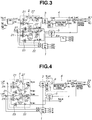
- FIG. 2 is a diagram of a main circuit of the three-phase neutral point clamped power conversion apparatus connected with the system. Between three-phase system voltages Vrs, Vst, Vtr and the three-phase neutral point clamped power conversion apparatus, there are provided input filters Lf, Cf.
- FIG. 3 is a block diagram showing a dc voltage control and a current control of FIG. 2 .
- the system voltages Vrs, Vst and Vtr are measured by using the voltage Vrs as a reference voltage in FIGS. 2 and 3 , and the phase of the system or system phase pll_out is determined by using PLL (Phase Locked Loop) circuit.
- PLL Phase Locked Loop
- the system phase pll_out is used in the three-phase to two-phase converters or converting sections 1 and 5 and the two-phase to three-phase converter or converting section 3.
- the three-phase to two-phase converter 1 converts the system currents Ir, Is, It to the detected currents Id_det, Iq_det on the basis of the system phase pll_out.
- the two-phase to three-phase converter 3 converts the two-phase command voltage Vd_cmd to the three-phase command voltage V_cmd on the basis of the system phase pll_out.
- the three-phase to two-phase converter 5 converts the limit processed command voltage V_cmd" to the feedback quantities Vd_back and Vq_back on the basis of the system phase pl_out.
- the command currents Id_cmd and Iq_cmd used for the current control are determined by determining a deviation between the dc command voltage Vdc_cmd (the command of voltage across the PN terminals in FIG. 2 ) and the sum of the dc voltages Vdc1 and Vdc2, and applying AVR (voltage control: Automatic Voltage Regulator).
- AVR voltage control: Automatic Voltage Regulator
- the apparatus according to the embodiment 2 can prevent interference between the current control and the neutral point potential control, restrain the integral action and thereby provide a stable control characteristic despite the limitation often imposed on the limiter processed command voltage V_cmd" when the corrected command voltage V_cmd' reaches the threshold at the time of voltage increasing operation of the power conversion apparatus.
- FIG. 4 shows the control circuit according to the embodiment 3.
- a subtracting section 6 subtracts a zero-phase command voltage V0_cmd from the three-phase command voltage V_cmd, and thereafter the neutral point potential control is performed.
- the feedback quantities Vd_back and Vq_back can be calculated in the same manner as in the embodiment 1. Since the feedback quantities Vd_back and Vq_back after the three-phase to two-phase conversion are mathematically independent from the zero-phase voltage, there arises no problem.
- the zero-phase command voltage V0_cmd of FIG. 4 corresponds to a voltage command correction signal shown in (b) of FIG. 2 of Patent Document 3.
- the zero-phase modulation is added to the control circuit of the embodiment 2 in order to increase the range of the output voltage of the power conversion apparatus.
- FIG. 5 shows the control circuit according to the embodiment 4.
- the subtracting section 6 subtracts the zero-phase command voltage V0_cmd from the three-phase command voltage V_cmd, and thereafter the neutral point potential control is performed.
- the feedback quantities Vd_back and Vq_back can be calculated in the same manner as in the embodiment 1.
- the zero-phase command voltage of FIG. 5 corresponds to the voltage command correction signal shown in (b) of FIG. 2 of Patent Document 3.
Landscapes
- Engineering & Computer Science (AREA)
- Power Engineering (AREA)
- Control Of Ac Motors In General (AREA)
- Inverter Devices (AREA)
Applications Claiming Priority (2)
| Application Number | Priority Date | Filing Date | Title |
|---|---|---|---|
| JP2014213279A JP6264257B2 (ja) | 2014-10-20 | 2014-10-20 | 三相中性点クランプ式の電力変換装置 |
| PCT/JP2015/078446 WO2016063723A1 (fr) | 2014-10-20 | 2015-10-07 | Dispositif de conversion de puissance triphasé bloqué au point neutre |
Publications (2)
| Publication Number | Publication Date |
|---|---|
| EP3208931A1 true EP3208931A1 (fr) | 2017-08-23 |
| EP3208931A4 EP3208931A4 (fr) | 2018-05-23 |
Family
ID=55760767
Family Applications (1)
| Application Number | Title | Priority Date | Filing Date |
|---|---|---|---|
| EP15852818.2A Ceased EP3208931A4 (fr) | 2014-10-20 | 2015-10-07 | Dispositif de conversion de puissance triphasé bloqué au point neutre |
Country Status (5)
| Country | Link |
|---|---|
| US (1) | US10574163B2 (fr) |
| EP (1) | EP3208931A4 (fr) |
| JP (1) | JP6264257B2 (fr) |
| RU (1) | RU2666125C1 (fr) |
| WO (1) | WO2016063723A1 (fr) |
Families Citing this family (2)
| Publication number | Priority date | Publication date | Assignee | Title |
|---|---|---|---|---|
| WO2020031526A1 (fr) * | 2018-08-07 | 2020-02-13 | 日本電産株式会社 | Dispositif de commande d'entraînement, dispositif d'entraînement et dispositif de direction assistée |
| TWI869003B (zh) * | 2023-10-25 | 2025-01-01 | 國立臺灣大學 | 具有中性線偏置電流補償功能的功率調節器及其控制方法 |
Family Cites Families (21)
| Publication number | Priority date | Publication date | Assignee | Title |
|---|---|---|---|---|
| SU1056147A1 (ru) * | 1981-01-16 | 1983-11-23 | Новосибирский Научно-Исследовательский,Проектно-Конструкторский И Технологический Институт Комплектного Электропривода | Регул тор тока трехфазной нагрузки |
| JPH01298959A (ja) * | 1988-05-27 | 1989-12-01 | Mitsubishi Electric Corp | Pwmコンバータ装置 |
| JP3102499B2 (ja) * | 1991-02-28 | 2000-10-23 | 株式会社東芝 | 中性点クランプ式電力変換器の制御装置 |
| JP2500140B2 (ja) | 1993-02-01 | 1996-05-29 | 株式会社東芝 | 中性点クランプ式コンバ―タの制御装置 |
| US5790396A (en) * | 1995-12-19 | 1998-08-04 | Kabushiki Kaisha Toshiba | Neutral point clamped (NPC) inverter control system |
| JP3186962B2 (ja) * | 1995-12-19 | 2001-07-11 | 株式会社東芝 | Npcインバータ装置 |
| KR19990077114A (ko) | 1996-01-10 | 1999-10-25 | 가나이 쓰도무 | 다중레벨 전력변환장치 |
| JP3233097B2 (ja) | 1998-04-03 | 2001-11-26 | 株式会社日立製作所 | 電力変換装置とその制御方法 |
| JP2003111433A (ja) * | 2001-09-27 | 2003-04-11 | Mitsubishi Electric Corp | 中性点クランプ式3レベルインバータ装置 |
| WO2007135730A1 (fr) * | 2006-05-23 | 2007-11-29 | Mitsubishi Denki Kabushiki Kaisha | Convertisseur d'énergie |
| JP5463289B2 (ja) * | 2008-08-22 | 2014-04-09 | 東芝三菱電機産業システム株式会社 | 電力変換装置 |
| KR101313386B1 (ko) * | 2009-03-25 | 2013-10-14 | 미쓰비시덴키 가부시키가이샤 | 회전 전기 기기의 제어 장치 및 제어 방법 |
| US8508166B2 (en) * | 2009-08-10 | 2013-08-13 | Emerson Climate Technologies, Inc. | Power factor correction with variable bus voltage |
| JP5622437B2 (ja) * | 2010-05-10 | 2014-11-12 | 株式会社東芝 | 中性点クランプ式電力変換装置 |
| US8441820B2 (en) * | 2010-09-29 | 2013-05-14 | General Electric Company | DC-link voltage balancing system and method for multilevel converters |
| JP5928865B2 (ja) * | 2010-11-18 | 2016-06-01 | 富士電機株式会社 | 非接触給電装置の制御方法 |
| KR101562418B1 (ko) * | 2011-07-05 | 2015-10-22 | 엘에스산전 주식회사 | 매입형 영구자석 동기 전동기의 구동장치 |
| JP5803681B2 (ja) * | 2012-01-12 | 2015-11-04 | 株式会社明電舎 | Pwm電力変換器の並列運転装置 |
| WO2014174667A1 (fr) * | 2013-04-26 | 2014-10-30 | 富士電機株式会社 | Dispositif de suppression de résonance |
| JP6342293B2 (ja) * | 2014-10-20 | 2018-06-13 | 株式会社東芝 | 中性点クランプ形電力変換装置およびその制御方法 |
| KR102431991B1 (ko) * | 2015-03-13 | 2022-08-16 | 삼성전자주식회사 | 모터 구동 장치 |
-
2014
- 2014-10-20 JP JP2014213279A patent/JP6264257B2/ja active Active
-
2015
- 2015-10-07 WO PCT/JP2015/078446 patent/WO2016063723A1/fr not_active Ceased
- 2015-10-07 US US15/516,985 patent/US10574163B2/en active Active
- 2015-10-07 RU RU2017115764A patent/RU2666125C1/ru active
- 2015-10-07 EP EP15852818.2A patent/EP3208931A4/fr not_active Ceased
Also Published As
| Publication number | Publication date |
|---|---|
| WO2016063723A1 (fr) | 2016-04-28 |
| US10574163B2 (en) | 2020-02-25 |
| RU2666125C1 (ru) | 2018-09-06 |
| EP3208931A4 (fr) | 2018-05-23 |
| JP6264257B2 (ja) | 2018-01-24 |
| JP2016082760A (ja) | 2016-05-16 |
| US20170302206A1 (en) | 2017-10-19 |
Similar Documents
| Publication | Publication Date | Title |
|---|---|---|
| KR101560669B1 (ko) | 펄스폭변조 전력변환기의 병렬운전 장치 | |
| US9509233B2 (en) | Power converter, power generation system, control apparatus, and power conversion method | |
| US8736220B2 (en) | Inverter control device and power conversion device | |
| US11601080B2 (en) | Motor control device | |
| EP3439163B1 (fr) | Convertisseur de puissance | |
| JP5717808B2 (ja) | 同期電動機の電流制御装置 | |
| US9935567B2 (en) | Rotating electric machine control device | |
| US9871482B2 (en) | Power conversion device | |
| US10199971B2 (en) | Motor controller, flux command generator, and method for generating flux command | |
| US10574163B2 (en) | Three-phase neutral-point-clamped power conversion device | |
| JPH09172783A (ja) | Npcインバータ装置 | |
| US11682998B2 (en) | Motor control method and motor control apparatus | |
| KR20170101130A (ko) | 서보 앰프의 전압 보상 장치 및 서보 앰프의 전압 보상 방법 | |
| US12021469B2 (en) | Rotating machine control device | |
| JP4766456B2 (ja) | 交流電動機の制御装置およびその制御方法 | |
| CN114026779B (zh) | 电力转换装置、电力转换控制装置及控制方法 | |
| WO2016063724A1 (fr) | Dispositif de conversion de puissance triphasee a blocage de point neutre |
Legal Events
| Date | Code | Title | Description |
|---|---|---|---|
| STAA | Information on the status of an ep patent application or granted ep patent |
Free format text: STATUS: THE INTERNATIONAL PUBLICATION HAS BEEN MADE |
|
| PUAI | Public reference made under article 153(3) epc to a published international application that has entered the european phase |
Free format text: ORIGINAL CODE: 0009012 |
|
| STAA | Information on the status of an ep patent application or granted ep patent |
Free format text: STATUS: REQUEST FOR EXAMINATION WAS MADE |
|
| 17P | Request for examination filed |
Effective date: 20170519 |
|
| AK | Designated contracting states |
Kind code of ref document: A1 Designated state(s): AL AT BE BG CH CY CZ DE DK EE ES FI FR GB GR HR HU IE IS IT LI LT LU LV MC MK MT NL NO PL PT RO RS SE SI SK SM TR |
|
| AX | Request for extension of the european patent |
Extension state: BA ME |
|
| DAV | Request for validation of the european patent (deleted) | ||
| DAX | Request for extension of the european patent (deleted) | ||
| A4 | Supplementary search report drawn up and despatched |
Effective date: 20180424 |
|
| RIC1 | Information provided on ipc code assigned before grant |
Ipc: H02P 21/06 20160101ALI20180418BHEP Ipc: H02P 27/14 20060101ALI20180418BHEP Ipc: H02P 21/22 20160101ALI20180418BHEP Ipc: H02M 7/487 20070101AFI20180418BHEP |
|
| STAA | Information on the status of an ep patent application or granted ep patent |
Free format text: STATUS: EXAMINATION IS IN PROGRESS |
|
| 17Q | First examination report despatched |
Effective date: 20191211 |
|
| REG | Reference to a national code |
Ref country code: DE Ref legal event code: R003 |
|
| STAA | Information on the status of an ep patent application or granted ep patent |
Free format text: STATUS: THE APPLICATION HAS BEEN REFUSED |
|
| 18R | Application refused |
Effective date: 20201216 |