EP3208960A1 - Moduswandler und multimoduswellenleiterübertragungsvorrichtung und -verfahren - Google Patents
Moduswandler und multimoduswellenleiterübertragungsvorrichtung und -verfahren Download PDFInfo
- Publication number
- EP3208960A1 EP3208960A1 EP14905486.8A EP14905486A EP3208960A1 EP 3208960 A1 EP3208960 A1 EP 3208960A1 EP 14905486 A EP14905486 A EP 14905486A EP 3208960 A1 EP3208960 A1 EP 3208960A1
- Authority
- EP
- European Patent Office
- Prior art keywords
- waveguide
- mode
- signal
- multimode
- output
- Prior art date
- Legal status (The legal status is an assumption and is not a legal conclusion. Google has not performed a legal analysis and makes no representation as to the accuracy of the status listed.)
- Granted
Links
Images



Classifications
-
- G—PHYSICS
- G02—OPTICS
- G02B—OPTICAL ELEMENTS, SYSTEMS OR APPARATUS
- G02B6/00—Light guides; Structural details of arrangements comprising light guides and other optical elements, e.g. couplings
- G02B6/10—Light guides; Structural details of arrangements comprising light guides and other optical elements, e.g. couplings of the optical waveguide type
- G02B6/14—Mode converters
-
- G—PHYSICS
- G02—OPTICS
- G02B—OPTICAL ELEMENTS, SYSTEMS OR APPARATUS
- G02B6/00—Light guides; Structural details of arrangements comprising light guides and other optical elements, e.g. couplings
- G02B6/10—Light guides; Structural details of arrangements comprising light guides and other optical elements, e.g. couplings of the optical waveguide type
- G02B6/12—Light guides; Structural details of arrangements comprising light guides and other optical elements, e.g. couplings of the optical waveguide type of the integrated circuit kind
-
- G—PHYSICS
- G02—OPTICS
- G02B—OPTICAL ELEMENTS, SYSTEMS OR APPARATUS
- G02B6/00—Light guides; Structural details of arrangements comprising light guides and other optical elements, e.g. couplings
- G02B6/10—Light guides; Structural details of arrangements comprising light guides and other optical elements, e.g. couplings of the optical waveguide type
- G02B6/12—Light guides; Structural details of arrangements comprising light guides and other optical elements, e.g. couplings of the optical waveguide type of the integrated circuit kind
- G02B6/122—Basic optical elements, e.g. light-guiding paths
- G02B6/124—Geodesic lenses or integrated gratings
-
- G—PHYSICS
- G02—OPTICS
- G02B—OPTICAL ELEMENTS, SYSTEMS OR APPARATUS
- G02B6/00—Light guides; Structural details of arrangements comprising light guides and other optical elements, e.g. couplings
- G02B6/10—Light guides; Structural details of arrangements comprising light guides and other optical elements, e.g. couplings of the optical waveguide type
- G02B6/12—Light guides; Structural details of arrangements comprising light guides and other optical elements, e.g. couplings of the optical waveguide type of the integrated circuit kind
- G02B6/126—Light guides; Structural details of arrangements comprising light guides and other optical elements, e.g. couplings of the optical waveguide type of the integrated circuit kind using polarisation effects
-
- G—PHYSICS
- G02—OPTICS
- G02B—OPTICAL ELEMENTS, SYSTEMS OR APPARATUS
- G02B6/00—Light guides; Structural details of arrangements comprising light guides and other optical elements, e.g. couplings
- G02B6/10—Light guides; Structural details of arrangements comprising light guides and other optical elements, e.g. couplings of the optical waveguide type
- G02B6/12—Light guides; Structural details of arrangements comprising light guides and other optical elements, e.g. couplings of the optical waveguide type of the integrated circuit kind
- G02B6/13—Integrated optical circuits characterised by the manufacturing method
-
- G—PHYSICS
- G02—OPTICS
- G02B—OPTICAL ELEMENTS, SYSTEMS OR APPARATUS
- G02B6/00—Light guides; Structural details of arrangements comprising light guides and other optical elements, e.g. couplings
- G02B6/24—Coupling light guides
- G02B6/36—Mechanical coupling means
- G02B6/38—Mechanical coupling means having fibre to fibre mating means
- G02B6/3807—Dismountable connectors, i.e. comprising plugs
- G02B6/3873—Connectors using guide surfaces for aligning ferrule ends, e.g. tubes, sleeves, V-grooves, rods, pins, balls
- G02B6/3885—Multicore or multichannel optical connectors, i.e. one single ferrule containing more than one fibre, e.g. ribbon type
-
- H—ELECTRICITY
- H04—ELECTRIC COMMUNICATION TECHNIQUE
- H04B—TRANSMISSION
- H04B10/00—Transmission systems employing electromagnetic waves other than radio-waves, e.g. infrared, visible or ultraviolet light, or employing corpuscular radiation, e.g. quantum communication
- H04B10/25—Arrangements specific to fibre transmission
- H04B10/2581—Multimode transmission
-
- H—ELECTRICITY
- H04—ELECTRIC COMMUNICATION TECHNIQUE
- H04J—MULTIPLEX COMMUNICATION
- H04J14/00—Optical multiplex systems
- H04J14/04—Mode multiplex systems
-
- G—PHYSICS
- G02—OPTICS
- G02B—OPTICAL ELEMENTS, SYSTEMS OR APPARATUS
- G02B6/00—Light guides; Structural details of arrangements comprising light guides and other optical elements, e.g. couplings
- G02B6/10—Light guides; Structural details of arrangements comprising light guides and other optical elements, e.g. couplings of the optical waveguide type
- G02B6/12—Light guides; Structural details of arrangements comprising light guides and other optical elements, e.g. couplings of the optical waveguide type of the integrated circuit kind
- G02B2006/12083—Constructional arrangements
- G02B2006/121—Channel; buried or the like
-
- G—PHYSICS
- G02—OPTICS
- G02B—OPTICAL ELEMENTS, SYSTEMS OR APPARATUS
- G02B6/00—Light guides; Structural details of arrangements comprising light guides and other optical elements, e.g. couplings
- G02B6/10—Light guides; Structural details of arrangements comprising light guides and other optical elements, e.g. couplings of the optical waveguide type
- G02B6/12—Light guides; Structural details of arrangements comprising light guides and other optical elements, e.g. couplings of the optical waveguide type of the integrated circuit kind
- G02B6/122—Basic optical elements, e.g. light-guiding paths
- G02B6/125—Bends, branchings or intersections
-
- G—PHYSICS
- G02—OPTICS
- G02B—OPTICAL ELEMENTS, SYSTEMS OR APPARATUS
- G02B6/00—Light guides; Structural details of arrangements comprising light guides and other optical elements, e.g. couplings
- G02B6/24—Coupling light guides
- G02B6/26—Optical coupling means
- G02B6/28—Optical coupling means having data bus means, i.e. plural waveguides interconnected and providing an inherently bidirectional system by mixing and splitting signals
- G02B6/2804—Optical coupling means having data bus means, i.e. plural waveguides interconnected and providing an inherently bidirectional system by mixing and splitting signals forming multipart couplers without wavelength selective elements, e.g. "T" couplers, star couplers
- G02B6/2821—Optical coupling means having data bus means, i.e. plural waveguides interconnected and providing an inherently bidirectional system by mixing and splitting signals forming multipart couplers without wavelength selective elements, e.g. "T" couplers, star couplers using lateral coupling between contiguous fibres to split or combine optical signals
Definitions
- the present invention relates to the communications field, and in particular, to a mode converter, a multimode waveguide transmission apparatus, and method.
- a transmission capacity may be expanded by introducing a wavelength division multiplexing (WDM, Wavelength Division Multiplexing) technology, a polarization division multiplexing (PDM, Polarization Division Multiplexing) technology, and a mode division multiplexing (MDM, Mode Division Multiplexing) technology, and the WDM and PDM technologies have been applied to a single-mode optical waveguide.
- WDM wavelength division multiplexing
- PDM Polarization Division Multiplexing
- MDM Mode Division Multiplexing
- a multimode waveguide may greatly expand the transmission capacity by using the mode division multiplexing technology.
- the mode multiplexer and the mode demultiplexer may implement the short-range optical interconnection by using the multimode waveguide.
- a multimode demultiplexer is used to demultiplex an input multimode signal into a single-mode waveguide, and then a multimode multiplexer is used to multiplex the signal into a multimode waveguide, so as to complete a conversion between different modes.
- an insertion loss (the insertion loss refers to a signal loss caused when a cable or a component is inserted between a transmitter and a receiver) is relatively large.
- all modes are converted in a unified manner, and when only some modes need to be converted, all the modes may need to be demultiplexed into a single-mode waveguide, and therefore, an overall size is relatively large, and an optical switching system cannot be easily implemented.
- Embodiments of the present invention provide a mode converter, a multimode waveguide transmission apparatus, and a method, so as to conveniently implement a conversion between different modes.
- a first aspect of the embodiments of the present invention provides a mode converter, including:
- the first conversion waveguide further includes an input bend waveguide, a connection waveguide, and an output bend waveguide, where the input coupling waveguide is configured to perform the evanescent wave coupling with the first signal transmitted in the input multimode waveguide, so that the first signal that is in the first mode and that is in the input multimode waveguide is coupled to a third mode of the input coupling waveguide; the output coupling waveguide is configured to perform the evanescent wave coupling with the output multimode waveguide, so that the first signal that is in the third mode and that is output by the output coupling waveguide is coupled to the second mode of the output multimode waveguide; the input bend waveguide is configured to prevent the connection waveguide from approaching the input multimode waveguide; the output bend waveguide is configured to prevent the connection waveguide from approaching the output multimode waveguide; and the connection waveguide is configured to separately connect the input bend waveguide and the output bend waveguide.
- connection waveguide includes a tapered waveguide; and widths of head and tail ends of the tapered waveguide are respectively equal to widths of the input bend waveguide and the output bend waveguide.
- a width of the input coupling waveguide meets the following condition: the first mode of the input multimode waveguide and the third mode of the input coupling waveguide meet a phase matching condition; a length of the input coupling waveguide meets the following condition: the first signal in the first mode is coupled to the third mode of the input coupling waveguide; a width of the output coupling waveguide meets the following condition: the third mode of the output multimode waveguide and the second mode of the output coupling waveguide meet the phase matching condition; and a length of the output coupling waveguide meets the following condition: the first signal that is in the third mode and that is output by the output coupling waveguide is coupled to the second mode of the output multimode waveguide.
- the input bend waveguide includes an S-shape waveguide, or a combination of a 90-degree circular waveguide and a straight waveguide; and the width of the input bend waveguide is equal to the width of the input coupling waveguide; and the output bend waveguide includes the S-shape waveguide, or a combination of the 90-degree circular waveguide and the straight waveguide; and the width of the output bend waveguide is equal to the width of the output coupling waveguide.
- widths of the input multimode waveguide and the output multimode waveguide are the same; or widths of the input multimode waveguide and the output multimode waveguide are different.
- the input multimode waveguide is further configured to receive a second signal, and a mode of the second signal is a fourth mode; and the multimode waveguide transmission apparatus further includes a second conversion waveguide, where the second conversion waveguide has an input coupling waveguide with a third effective refractive index, and has an output coupling waveguide with a fourth effective refractive index; and the third effective refractive index is corresponding to an effective refractive index of the second signal that is in the fourth mode and that is in the input multimode waveguide, and the fourth effective refractive index is corresponding to an effective refractive index of the second signal that is in a fifth mode and that is in the output multimode waveguide; the second conversion waveguide is configured to: perform the evanescent wave coupling on the second signal transmitted in the input multimode waveguide, and couple the second signal to the fifth mode of the output multimode waveguide by using the output coupling waveguide
- the input multimode waveguide is further configured to receive a third signal in a sixth mode; and the input multimode waveguide is connected to the output multimode waveguide, and the third signal in the sixth mode is transmitted from the input multimode waveguide to the output multimode waveguide, and then is output by the output multimode waveguide.
- a second aspect of the embodiments of the present invention provides a multimode waveguide transmission apparatus, including:
- the mode converter is further configured to perform the mode conversion on a third signal that is input, and a mode of the third signal is a third mode before the first mode converter performs the mode conversion; and the multimode transmission waveguide is further configured to transmit the third signal, and in the first mode, the second mode, or the third mode, the first signal, the second signal, and the third signal are transmitted for the equal distance in the multimode transmission waveguide.
- the mode converter includes an input multimode waveguide, an output multimode waveguide, and a conversion waveguide, where the input multimode waveguide is configured to receive the first signal and the second signal; the conversion waveguide is configured to perform the mode conversion on the first signal and the second signal that are transmitted in the input multimode waveguide; and the output multimode waveguide is configured to output the first signal and the second signal that are obtained after the mode conversion.
- the conversion waveguide includes a first conversion waveguide, where the first conversion waveguide has an input coupling waveguide with a first effective refractive index, and has an output coupling waveguide with a second effective refractive index; and the first effective refractive index is corresponding to an effective refractive index of the first signal that is in the first mode and that is in the input multimode waveguide, and the second effective refractive index is corresponding to an effective refractive index of the first signal that is in the second mode and that is in the output multimode waveguide; and the first conversion waveguide is configured to: perform, by using the input coupling waveguide, evanescent wave coupling on the first signal that is in the first mode and that is transmitted in the input multimode waveguide, and couple the first signal to the second mode of the output multimode waveguide by using the output coupling waveguide, so as to obtain the first signal in the second mode.
- the first conversion waveguide further includes an input bend waveguide, a connection waveguide, and an output bend waveguide, where the input coupling waveguide is configured to perform the evanescent wave coupling with the first signal transmitted in the input multimode waveguide, so that the first signal that is in the first mode and that is in the input multimode waveguide is coupled to a fourth mode of the input coupling waveguide; the output coupling waveguide is configured to perform the evanescent wave coupling with the output multimode waveguide, so that the first signal that is in the fourth mode and that is output by the output coupling waveguide is coupled to the second mode of the output multimode waveguide; the input bend waveguide is configured to prevent the connection waveguide from approaching the input multimode waveguide; the output bend waveguide is configured to prevent the connection waveguide from approaching the output multimode waveguide; and the connection waveguide is configured to separately connect the input bend waveguide and the output bend waveguide.
- connection waveguide includes a tapered waveguide; and widths of head and tail ends of the tapered waveguide are respectively equal to widths of the input bend waveguide and the output bend waveguide.
- a width of the input coupling waveguide meets the following condition: the first mode of the input multimode waveguide and a fourth mode of the input coupling waveguide meet a phase matching condition; a length of the input coupling waveguide meets the following condition: the first signal in the first mode is coupled to the fourth mode of the input coupling waveguide; a width of the output coupling waveguide meets the following condition: the fourth mode of the output multimode waveguide and the second mode of the output coupling waveguide meet the phase matching condition; and a length of the output coupling waveguide meets the following condition: the first signal that is in the fourth mode and that is output by the output coupling waveguide is coupled to the second mode of the output multimode waveguide.
- the input bend waveguide includes an S-shape waveguide, or a combination of a 90-degree circular waveguide and a straight waveguide; and a width of the input bend waveguide is equal to a width of the input coupling waveguide; and the output bend waveguide includes the S-shape waveguide, or a combination of the 90-degree circular waveguide and the straight waveguide; and the width of the output bend waveguide is equal to the width of the output coupling waveguide.
- widths of the input multimode waveguide and the output multimode waveguide are the same; or widths of the input multimode waveguide and the output multimode waveguide are different.
- a third aspect of the embodiments of the present invention provides a signal transmission method, including:
- the mode converter includes the input multimode waveguide, the output multimode waveguide, and the first conversion waveguide.
- the first conversion waveguide performs, by using an input coupling waveguide, evanescent wave coupling on a first signal that is in a first mode and that is transmitted in the input multimode waveguide, and couples the first signal to a second mode of the output multimode waveguide by using an output coupling waveguide.
- a mode conversion of a signal is completed by using only one conversion device, thereby reducing an insertion loss in a signal conversion process.
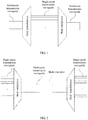
- FIG. 2 for a schematic diagram of multimode waveguide interconnection, refer to FIG. 2 .
- a mode converter needs to be disposed between a mode multiplexer and a mode demultiplexer in FIG. 2 , so as to perform a mode conversion on the signal that is in multiple modes and that is in the multimode waveguide.
- an embodiment of a mode converter in this embodiment of the present invention includes:
- the input multimode waveguide 121 is configured to receive a first signal, and a mode of the first signal is a first mode.
- the first conversion waveguide 123 has an input coupling waveguide 1231 with a first effective refractive index, and has an output coupling waveguide 1235 with a second effective refractive index; and the first effective refractive index is corresponding to an effective refractive index of the first signal that is in the first mode and that is in the input multimode waveguide, and the second effective refractive index is corresponding to an effective refractive index of the first signal that is in a second mode and that is in the output multimode waveguide.
- the input coupling waveguide 1231 and the output coupling waveguide 1235 each may be a multimode waveguide, or may be a single-mode waveguide, and no specific limitation is imposed herein.
- the first conversion waveguide 123 is configured to: perform, by using the input coupling waveguide 1231, evanescent wave coupling on the first signal that is in the first mode and that is transmitted in the input multimode waveguide, and couple the first signal to the second mode of the output multimode waveguide by using the output coupling waveguide 1235, so as to obtain the first signal in the second mode.
- the output multimode waveguide 122 is configured to output the first signal in the second mode.
- widths of the input multimode waveguide and the output multimode waveguide may be the same, or may be different. This is specifically determined according to an actual signal mode and the effective refractive index, and no limitation is imposed herein.
- the first conversion waveguide in this embodiment of the present invention may further include an input bend waveguide 1232, a connection waveguide 1233, and an output bend waveguide 1234.
- Waveguide widths of input coupling waveguides 1231 are different from each other, and waveguide widths of output coupling waveguides 1235 are different from each other.
- the input coupling waveguide 1231 is configured to perform the evanescent wave coupling with the first signal transmitted in the input multimode waveguide, so that the first signal that is in the first mode and that is in the input multimode waveguide is coupled to a third mode of the input coupling waveguide.
- a width of the input coupling waveguide meets the following condition: the first mode of the input multimode waveguide and the third mode of the input coupling waveguide meet a phase matching condition; and a length of the input coupling waveguide meets the following condition: the first signal in the first mode is coupled to the third mode of the input coupling waveguide.
- the output coupling waveguide 1235 is configured to perform the evanescent wave coupling with the output multimode waveguide, so that the first signal that is in the third mode and that is output by the output coupling waveguide is coupled to the second mode of the output multimode waveguide.
- a width of the output coupling waveguide meets the following condition: the third mode of the output multimode waveguide and the second mode of the output coupling waveguide meet the phase matching condition; and a length of the output coupling waveguide meets the following condition: the first signal that is in the third mode and that is output by the output coupling waveguide is coupled to the second mode of the output multimode waveguide.
- the input bend waveguide 1232 is configured to prevent the connection waveguide from approaching the input multimode waveguide.
- the output bend waveguide 1234 is configured to prevent the connection waveguide from approaching the output multimode waveguide.
- connection waveguide 1233 is configured to connect the input bend waveguide and the output bend waveguide.
- the effective refractive index in this embodiment of the present invention is an important and a common parameter in an optical waveguide, and is related to a dimension of a waveguide and a refractive index of a material of the waveguide. Once the dimension and the material that are of the waveguide are determined, the effective refractive index of the waveguide is also determined. Effective refractive indexes that are in different modes and that are transmitted in the waveguide are different from each other, as shown in the following Table 1.
- Table 1 Waveguide widths are equal to 2 ⁇ m TE 0 2.828 TM 0 2.04 TE 1 2.749 TM 1 1.948 TE 2 2.613 TM 2 1.793 TE 3 2.412 TM 3 1.578 TE 4 2.131 TE 5 1.758
- TE x and TM x represent different modes.
- the effective refractive index in each mode is shown in Table 1.
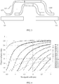
- FIG. 5 shows a relationship between the effective refractive index and the waveguide width. Curves in FIG. 5 represent different modes. A straight dashed line with a horizontal coordinate value of 2 indicates the effective refractive index in each mode when the waveguide widths are 2 ⁇ m.
- a waveguide width of the input multimode waveguide is 1.7 ⁇ m
- a waveguide width of the output multimode waveguide is 1.7 ⁇ m
- a waveguide width of the input coupling waveguide is 0.4 ⁇ m
- a waveguide width of the output multimode waveguide is 0.55 ⁇ m
- all waveguide heights are 0.22 ⁇ m.
- This group of the parameters may be used to convert the TE 3 mode of a multimode waveguide to the TE 2 mode (for the specific parameters, refer to Table 2).
- the first signal in the first mode when the first signal in the first mode is transmitted to the input multimode waveguide 121, because the input multimode waveguide 121 and the input coupling waveguide 1231 in the first conversion waveguide 123 meet the phase matching condition, the first signal is coupled to the first conversion waveguide 123 for transmission. In this case, the mode of the first signal is converted from the original first mode to the third mode corresponding to the first conversion waveguide 123.
- the first signal in the third mode is transmitted to the output coupling waveguide 1235 in the first conversion waveguide 123, because the output multimode waveguide 123 and the output coupling waveguide 1235 in the first conversion waveguide 123 meet the phase matching condition, the first signal is coupled to the output multimode waveguide 122 for transmission.
- the mode of the first signal is converted, according to the second effective refractive index corresponding to the output coupling waveguide 1235 in the first conversion waveguide 123, from the third mode to the second mode corresponding to the output multimode waveguide 122.
- the first signal is converted from the first mode to the second mode.
- a conversion waveguide in this embodiment of the present invention further includes a second conversion waveguide.
- the second conversion waveguide has an input coupling waveguide with a third effective refractive index, and has an output coupling waveguide with a fourth effective refractive index; and the third effective refractive index is corresponding to an effective refractive index of the second signal that is in the fourth mode and that is in the input multimode waveguide, and the fourth effective refractive index is corresponding to an effective refractive index of the second signal that is in a fifth mode and that is in the output multimode waveguide.
- the second conversion waveguide is configured to: perform the evanescent wave coupling on the second signal transmitted in the input multimode waveguide, and couple the second signal to the fifth mode of the output multimode waveguide by using the output coupling waveguide, so as to obtain the second signal in the fifth mode.
- the mode converter may include multiple conversion waveguides.
- One conversion waveguide performs a mode conversion on signals in one mode, and no specific limitation is imposed herein.
- the input multimode waveguide is further configured to receive a third signal in a sixth mode.
- the input multimode waveguide is connected to the output multimode waveguide, and the third signal in the sixth mode is transmitted from the input multimode waveguide to the output multimode waveguide, and then is output by the output multimode waveguide.
- the mode converter in this embodiment of the present invention may further transmit a signal that does not require the mode conversion (for example, the third signal in the sixth mode).
- a signal that does not require the mode conversion for example, the third signal in the sixth mode.
- the first effective refractive index and “the second effective refractive index” represent only two different effective refractive indexes, and do not specifically refer to any effective refractive index in actual application;
- the first signal and “the second signal” represent two different signals, and do not specifically refer to any signal in actual application;
- the first mode” and “the second mode” represent two different signal modes, and do not specifically refer to any signal mode in actual application;
- any concept of "N th " is only for ease of description, and does not specifically refer to any specific concept in actual application.
- a multimode transmission waveguide transmits multiple signals to the input multimode waveguide 121.
- the signals are corresponding to different modes.
- the input coupling waveguide 1231 performs the evanescent wave coupling with the first signal that is in the first mode and that is transmitted in the input multimode waveguide 121 (in this case, the first signal is converted from the first mode to the third mode, and the effective refractive index that is in the third mode and that is of the input coupling waveguide 1231 is the first effective refractive index); when the signal is transmitted in the conversion waveguide 123, after the signal enters the output coupling waveguide 1235 by using the connection waveguide in the conversion waveguide 123 (in this case, the first signal is still in the third mode, but the effective refractive index that is in the third mode and that is of the output coupling waveguide 1235 is the second effective refr
- the mode converter includes the input multimode waveguide, the output multimode waveguide, and the first conversion waveguide.
- the first conversion waveguide performs, by using an input coupling waveguide, evanescent wave coupling on a first signal that is in a first mode and that is transmitted in the input multimode waveguide, and couples the first signal to the second mode of the output multimode waveguide by using an output coupling waveguide.
- a mode conversion of a signal is completed by using only one conversion device, thereby reducing an insertion loss in a signal conversion process.
- an embodiment of a mode converter in this embodiment of the present invention includes:
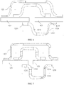
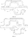
- widths of the input multimode waveguide 121 and the output multimode waveguide 122 may be the same, as shown in FIG. 6 and FIG. 7 ; optionally, widths of the input multimode waveguide 121 and the output multimode waveguide 122 may be different, as shown in FIG. 8 and FIG. 9 , so as to implement a mode conversion between multimode waveguides that have different widths.
- the conversion waveguide 123 includes the input coupling waveguide 1231, an input bend waveguide 1232, a connection waveguide 1233, an output bend waveguide 1234, and the output coupling waveguide 1235.
- Waveguide widths of input coupling waveguides 1231 are different from each other, and waveguide widths of output coupling waveguides 1235 are different from each other.
- the corresponding two modes meet a phase matching condition.
- An energy coupling and the mode conversion may be performed between modes that meet the phase matching condition.
- One mode of one waveguide may be coupled, by selecting appropriate waveguide spacing and an appropriate coupling length, to the other mode corresponding to the other waveguide.
- the input bend waveguide 1232 is configured to prevent the connection waveguide 1233 from approaching the input multimode waveguide 121. Specifically, after the input coupling waveguide 1231 completes a signal coupling, to prevent the first signal obtained after the mode conversion from being reversely coupled to the input multimode waveguide 121, the input bend waveguide 1232 needs to be disposed.
- the output bend waveguide 1234 is configured to prevent the connection waveguide 1233 from approaching the output multimode waveguide. Specifically, after the output coupling waveguide 1235 couples a signal to the output multimode waveguide 122, to prevent the first signal obtained after the mode conversion from being reversely coupled to the output coupling waveguide 1235, the output bend waveguide 1234 needs to be disposed.
- the input bend waveguide 1232 or the output bend waveguide 1234 may be an S-shape waveguide, or a combination of a 90-degree circular waveguide and a straight waveguide; and a width of the input bend waveguide is equal to a width of the input coupling waveguide, and a width of the output bend waveguide is equal to a width of the output coupling waveguide.
- the output bend waveguide 1234 and the input bend waveguide 1232 may be the S-shape waveguide, refer to FIG. 6 or FIG. 8 ; for a scenario in which the output bend waveguide 1234 and the input bend waveguide 1232 may be a combination of the 90-degree circular waveguide and the straight waveguide, refer to FIG. 7 or FIG. 9 .
- connection waveguide 1233 is configured to connect to the input bend waveguide 1232 and the output bend waveguide 1234.
- the connection waveguide may include a tapered waveguide; widths of head and tail ends of the tapered waveguide are respectively equal to the widths of the input bend waveguide 1232 and the output bend waveguide 1233.
- the connection waveguide may include a straight waveguide, and the straight waveguide is connected to the tapered waveguide, so as to adapt to a position and a length that are of the input bend waveguide 1232 or the output bend waveguide 1233.
- the tapered waveguide may be an adiabatic tapered waveguide; when performing the mode conversion on the signal, the adiabatic tapered waveguide may effectively reduce an extra energy loss.
- connection waveguide uses the adiabatic tapered waveguide; when the mode conversion is performed on N signals, those signals that do not require the mode conversion may be directly retained in a multimode transmission waveguide, so as to decrease a quantity of coupling waveguides. As shown in FIG. 10 and FIG. 11 , those signals that do not require the mode conversion are directly transmitted from the input multimode waveguide 121 to the output multimode waveguide 122.
- the mode converter has a simple device structure, is compatible with the CMOS process, and can be easily integrated; in addition, the mode converter in this embodiment of the present invention imposes no limitation on a mode quantity and a polarization state that are of a multimode waveguide, and can increase or decrease a quantity of conversion waveguides and some components according to an actual situation, so as to adapt to an actual application scenario; further, the mode converter can be used in a multi-wavelength condition.
- This embodiment of the present invention further provides a multimode waveguide transmission apparatus, which is configured to resolve problems of the dispersion delay and the power imbalance that are caused by different modes of the signal in the multimode signal transmission process of a system on chip.
- a multimode waveguide transmission apparatus which is configured to resolve problems of the dispersion delay and the power imbalance that are caused by different modes of the signal in the multimode signal transmission process of a system on chip.
- the multimode waveguide transmission apparatus and a corresponding signal transmission method provided in this embodiment of the present invention are mainly an improvement on a multimode waveguide connection part between a mode multiplexer and a mode demultiplexer in FIG. 2 .
- an embodiment of a multimode waveguide transmission apparatus in this embodiment of the present invention includes:
- a connection relationship between a quantity of segments of the multimode transmission waveguides 11 and the mode converters 12 may be as follows: The quantity of the segments of the multimode transmission waveguides 11 and a quantity of the mode converters 12 may be equal, and the first multimode transmission waveguide 11 is disposed before the first mode converter 12, as shown in FIG. 5 ; optionally, the quantity of the segments of the multimode transmission waveguides 11 and a quantity of the mode converters 12 may be equal, and the first mode converter 12 is disposed before the first multimode transmission waveguide 11; optionally, the quantity of the segments of the multimode transmission waveguides 11 may be one more than a quantity of the mode converters 12, and the first multimode transmission waveguide 11 is disposed before the first mode converter 12.
- the M or M+1 multimode transmission waveguides 11 may have the same physical structure.
- the mode converter 12 is configured to separately perform the mode conversion on a first signal and a second signal that are input, where modes of the first signal and the second signal are respectively a first mode and a second mode before the first mode converter performs the mode conversion, and when the last mode converter completes the conversion, a mode of each signal is the same as a mode before the first mode conversion.
- the multimode transmission waveguide 11 is configured to transmit the first signal and the second signal, where in the first mode or the second mode, the first signal and the second signal are transmitted for an equal distance in the multimode transmission waveguide.
- the described "equal transmission distance" is not strictly equal.
- there may be a specific error range which is specifically subject to an effect of compensating for a dispersion delay and a power imbalance that are between modes of a multimode waveguide.
- a first signal be a signal 1
- a second signal be a signal 2
- a first mode be a mode 1
- a second mode be a mode 1
- a first multimode transmission waveguide be a multimode transmission waveguide 111
- a second multimode transmission waveguide be a multimode transmission waveguide 112.
- the signal 1 in the mode 0 and the signal 2 in the mode 1 are transmitted in the first multimode transmission waveguide, and the signal 1 and the signal 2 are transmitted from the first multimode transmission waveguide to a first mode converter.
- the signal 1 is converted from the mode 0 to the mode 1
- the signal 2 is converted from the mode 1 to the mode 0, and the signal 1 in the mode 1 and the signal 2 in the mode 0 are transmitted to the second multimode transmission waveguide, and then are transmitted to a second mode converter.
- the signal 1 is converted from the mode 1 to the mode 0, the signal 2 is converted from the mode 1 to the mode 0, and then the signal 1 in the mode 0 and the signal 2 in the mode 1 are output.
- the signal 1 and the signal 2 are transmitted for an equal distance in the multimode transmission waveguide.
- the signal 1 and the signal 2 are also transmitted for an equal distance in the multimode transmission waveguide.
- the distance transmitted in the multimode transmission waveguide includes the sum of distances transmitted in the multimode transmission waveguide 111 and the multimode transmission waveguide 112. It may be understood that, regardless of a quantity of segments included in the multimode transmission waveguide, this embodiment of the present invention focuses on the sum of lengths of multiple multimode transmission waveguides.
- the mode converter is further configured to perform the mode conversion on a third signal that is input, and a mode of the third signal is a third mode before the first mode converter performs the mode conversion.
- the multimode transmission waveguide is further configured to transmit the third signal, and in the first mode, the second mode, or the third mode, the first signal, the second signal, and the third signal are transmitted for the equal distance in the multimode transmission waveguide.
- a first signal be a signal 1
- a second signal be a signal 2
- a third signal be a signal 3
- a first mode be a mode 0,
- a second mode be a mode 1
- a third mode be a mode 2
- a first multimode transmission waveguide be a multimode transmission waveguide 111
- a second multimode transmission waveguide be a multimode transmission waveguide 112
- a third multimode transmission waveguide be a multimode transmission waveguide 113.
- the signal 1 in the mode 0, the signal 2 in the mode 1, and the signal 3 in the mode 2 are transmitted in the first multimode transmission waveguide, and the signal 1, the signal 2 and the signal 3 are transmitted from the first multimode transmission waveguide to a first mode converter.
- the signal 1 is converted from the mode 0 to the mode 1
- the signal 2 is converted from the mode 1 to the mode 2
- the signal 3 is converted from the mode 2 to the mode 0.
- the signal 1 in the mode 1, the signal 2 in the mode 2, and the signal 3 in the mode 0 are transmitted to the second multimode transmission waveguide, and then are transmitted to a second mode converter.
- the signal 1 is converted from the mode 1 to the mode 2
- the signal 2 is converted from the mode 2 to the mode 0
- the signal 3 is converted from the mode 0 to the mode 1.
- the signal 1 in the mode 2, the signal 2 in the mode 0, and the signal 3 in the mode 1 are transmitted to the third multimode transmission waveguide, and then are transmitted to a third mode converter.
- the signal 1 is converted from the mode 2 to the mode 0, the signal 2 is converted from the mode 0 to the mode 1, and the signal 3 is converted from the mode 1 to the mode 2; and then the signal 1 in the mode 0, the signal 2 in the mode 1, and the signal 3 in the mode 2 are output.
- the signal 1, the signal 2, and the signal 3 are transmitted for an equal distance in the multimode transmission waveguide.
- the signal 1, the signal 2, and the signal 3 are transmitted for an equal distance in the multimode transmission waveguide.
- the signal 1, the signal 2, and the signal 3 are transmitted for an equal distance in the multimode transmission waveguide.
- the distance transmitted in the multimode transmission waveguide includes the sum of distances transmitted in the multimode transmission waveguide 111, the multimode transmission waveguide 112, and the multimode transmission waveguide 113.
- a quantity of mode converters may be greater than a quantity of signals that require a mode conversion. That is, if N signals corresponding to N modes need to be transmitted in a multimode waveguide transmission apparatus in this embodiment of the present invention, in a process of performing the mode conversion by multiple mode converters, not only the conversion between the N modes is performed on the N signals, but also the conversion between M (M is an integer greater than N) modes can be completed, provided that the M modes include the N modes, and when the last mode converter completes the conversion, a mode of each signal is the same as a mode before the first mode conversion.
- the N signals in their respective original modes are transmitted from a first multimode transmission waveguide 11 to a first mode converter 12.
- the mode converter 12 couples signals received by an input multimode waveguide 121 to a conversion waveguide 123, and after a mode conversion of each signal is completed, each signal is output by an output multimode waveguide 122 to a second multimode transmission waveguide 11.
- the N signals are transmitted in the second multimode transmission waveguide 11 after the first mode converter 12 completes the mode conversion.
- a signal is transmitted for a fixed distance in a multimode transmission waveguide 11; when being transmitted to the last multimode transmission waveguide 11, each signal undergoes a transmission state in at least N modes; and after the last multimode transmission waveguide 11 transmits the N signals to the last mode converter 12, the last mode conversion is that a mode X is converted to the original mode of the signal before the first mode conversion, where the mode X may be any one of N modes corresponding to the N signals except the original mode.
- any two of the N signals are transmitted for an equal distance in the multimode transmission waveguide, and the N signals are all output to a mode demultiplexer in their respective original modes.
- At least N mode converters 12 may be implemented based on a same physical structure or different physical structures, provided that an effect produced by a cascade of the at least N mode converters 12 is that "the conversion between different modes is performed on each signal for at least N times, and during the last conversion, the mode of each signal is the same as the mode before the first mode conversion".
- the multimode transmission waveguide 11 also has N segments of equal lengths. If the quantity of the mode converters 12 is greater than N, at least one mode is converted twice in the mode conversion performed by the at least N mode converters; although the quantity of the segments of the multimode transmission waveguides 11 is equal to the quantity of the mode converters 12, the lengths of the segments may be different, that is, when a mode is converted twice, the sum of distances of subsequent two corresponding multimode transmission waveguides 11 is equal to a distance of the multimode transmission waveguide 11 when a mode is converted only once.
- each signal is transmitted for a distance in a multimode transmission waveguide, the conversion between different modes is performed on each signal for at least N times, and in any one of the N modes, any two of the N signals are transmitted for an equal distance in the multimode transmission waveguide, thereby compensating for a dispersion delay and a power imbalance that are between modes of a multimode waveguide in a system on chip.
- an embodiment of a mode converter 12 in this embodiment of the present invention includes:
- the first conversion waveguide has an input coupling waveguide with a first effective refractive index, and has an output coupling waveguide with the second effective refractive index; and the first effective refractive index is corresponding to an effective refractive index of the first signal that is in a first mode and that is in the input multimode waveguide, and the second effective refractive index is corresponding to an effective refractive index of the first signal that is in the second mode and that is in the output multimode waveguide.
- the first conversion waveguide is configured to: perform, by using the input coupling waveguide, evanescent wave coupling on the first signal that is in the first mode and that is transmitted in the input multimode waveguide, and couple the first signal to the second mode of the output multimode waveguide by using the output coupling waveguide, so as to obtain the first signal in the second mode.
- widths of the input multimode waveguide 121 and the output multimode waveguide 122 may be the same, as shown in FIG. 6 and FIG. 7 ; optionally, widths of the input multimode waveguide 121 and the output multimode waveguide 122 may be different, as shown in FIG. 8 and FIG. 9 , so as to implement a mode conversion between multimode waveguides that have different widths.
- the first conversion waveguide 123 includes the input coupling waveguide 1231, an input bend waveguide 1232, a connection waveguide 1233, an output bend waveguide 1234, and the output coupling waveguide 1235.
- Waveguide widths of input coupling waveguides 1231 are different from each other, and waveguide widths of output coupling waveguides 1235 are different from each other.
- the input bend waveguide 1232 or the output bend waveguide 1234 may be an S-shape waveguide, or a combination of a 90-degree circular waveguide and a straight waveguide; and a width of the input bend waveguide is equal to a width of the input coupling waveguide, and a width of the output bend waveguide is equal to a width of the output coupling waveguide.
- the output bend waveguide 1234 and the input bend waveguide 1232 may be the S-shape waveguide, refer to FIG. 6 or FIG. 8 ; for a scenario in which the output bend waveguide 1234 and the input bend waveguide 1232 may be a combination of the 90-degree circular waveguide and the straight waveguide, refer to FIG. 7 or FIG. 9 .
- connection waveguide 1233 is configured to connect to the input bend waveguide 1232 and the output bend waveguide 1234.
- the connection waveguide may include a tapered waveguide; widths of head and tail ends of the tapered waveguide are respectively equal to the widths of the input bend waveguide 1232 and the output bend waveguide 1233.
- the connection waveguide may include a straight waveguide, and the straight waveguide is connected to the tapered waveguide, so as to adapt to a position and a length that are of the input bend waveguide 1232 or the output bend waveguide 1233.
- the tapered waveguide may be an adiabatic tapered waveguide; when performing the mode conversion on the signal, the adiabatic tapered waveguide may effectively reduce an extra energy loss.
- N is a quantity of signals that require a mode conversion. If the quantity of the signals received by the input multimode waveguide is greater than N (that is, not all signals require a mode conversion), any conversion waveguide in the mode converter in a multimode waveguide transmission apparatus can couple the signals that do not require the mode conversion. As shown in FIG. 10 and FIG. 11 , those signals that do not require the mode conversion are directly transmitted from the input multimode waveguide 121 to the output multimode waveguide 122.
- an embodiment of the signal transmission method in this embodiment of the present invention includes:
- the multimode waveguide transmission apparatus receives the first signal and the second signal, where modes of the first signal and the second signal are respectively a first mode and a second mode before the first mode converter performs a mode conversion.
- the multimode waveguide transmission apparatus may be configured to handle problems of chromatic aberration and power imbalance transmission that are of at least two signals.
- the multimode waveguide transmission apparatus separately performs the mode conversion on the first signal and the second signal, and transmits, by using a multimode transmission waveguide, the first signal and the second signal that are obtained after the mode conversion, so that in the first mode or the second mode, the first signal and the second signal are transmitted for an equal distance in the multimode transmission waveguide.
- the multimode waveguide transmission apparatus outputs the first signal and the second signal, where modes of the first signal and the second signal that are output are the same as their respective modes before the first mode conversion.
- the mode converter in this embodiment of the present invention is a device that has a function of performing the mode conversion on the signal, which may be specifically a mode converter described in the embodiment of the present invention shown in FIG. 3 , or may be a mode converter shown in FIG. 1 .
- each signal is transmitted for a distance in a multimode transmission waveguide; the conversion between the two modes is performed on each signal for at least twice; and in either of the two modes, the two signals are transmitted for an equal distance in the multimode transmission waveguide, thereby compensating for a dispersion delay and a power imbalance that are between modes of a multimode waveguide in a system on chip.
- a mode converter in a multimode waveguide transmission apparatus separately couples the N signals received by an input multimode waveguide to different conversion waveguides, and after a mode conversion of the N signals is completed, the N signals are output by an output multimode waveguide in the multimode waveguide transmission apparatus to a second multimode transmission waveguide.
- the N signals are transmitted in the second multimode transmission waveguide after a first mode converter completes the mode conversion.
- a signal is transmitted for a fixed distance in a multimode transmission waveguide; when being transmitted to the last multimode transmission waveguide, each signal undergoes a transmission state in the at least N modes; and after the last multimode transmission waveguide transmits the N signals to the last mode converter, the last mode conversion is that a mode X is converted to an original mode of the signal before the first mode conversion, where the mode X may be any one of the N modes corresponding to the N signals except the original mode.
- the mode X may be any one of the N modes corresponding to the N signals except the original mode.
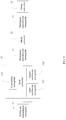
- the mode conversion of each signal may follow the following control logic:
- a specific conversion of each signal to a specific mode in the mode conversion may be randomly determined, or may be determined according to a preset mode conversion order (that is, various modes are numbered and sorted, and then are converted according to a fixed order), and no specific limitation is imposed herein.
Landscapes
- Physics & Mathematics (AREA)
- Engineering & Computer Science (AREA)
- General Physics & Mathematics (AREA)
- Optics & Photonics (AREA)
- Microelectronics & Electronic Packaging (AREA)
- Computer Networks & Wireless Communication (AREA)
- Signal Processing (AREA)
- Electromagnetism (AREA)
- Optical Integrated Circuits (AREA)
- Optical Communication System (AREA)
Applications Claiming Priority (1)
| Application Number | Priority Date | Filing Date | Title |
|---|---|---|---|
| PCT/CN2014/090614 WO2016070420A1 (zh) | 2014-11-07 | 2014-11-07 | 一种模式转换器、多模波导传输装置及方法 |
Publications (3)
| Publication Number | Publication Date |
|---|---|
| EP3208960A1 true EP3208960A1 (de) | 2017-08-23 |
| EP3208960A4 EP3208960A4 (de) | 2018-01-24 |
| EP3208960B1 EP3208960B1 (de) | 2019-09-11 |
Family
ID=55908435
Family Applications (1)
| Application Number | Title | Priority Date | Filing Date |
|---|---|---|---|
| EP14905486.8A Active EP3208960B1 (de) | 2014-11-07 | 2014-11-07 | Moduswandler |
Country Status (4)
| Country | Link |
|---|---|
| US (1) | US10353148B2 (de) |
| EP (1) | EP3208960B1 (de) |
| CN (1) | CN106797271B (de) |
| WO (1) | WO2016070420A1 (de) |
Cited By (1)
| Publication number | Priority date | Publication date | Assignee | Title |
|---|---|---|---|---|
| EP3993284A1 (de) * | 2020-10-28 | 2022-05-04 | Airbus (S.A.S.) | Optischer freiraumempfänger |
Families Citing this family (13)
| Publication number | Priority date | Publication date | Assignee | Title |
|---|---|---|---|---|
| CN105829930B (zh) * | 2014-10-24 | 2019-04-26 | 华为技术有限公司 | 模式复用解复用器和交换节点 |
| WO2016100989A2 (en) * | 2014-12-19 | 2016-06-23 | Cornell University | Processing of multimode optical signals |
| US9606293B2 (en) * | 2015-06-29 | 2017-03-28 | Elenion Technologies, Llc | Bent taper with varying widths for an optical waveguide |
| CN106842430A (zh) * | 2017-04-05 | 2017-06-13 | 电子科技大学 | 一种非对称定向耦合器 |
| FR3075990A1 (fr) * | 2017-12-21 | 2019-06-28 | Orange | Modes spatiaux multimodaux augmentes pour fibre optique |
| JP7061771B2 (ja) * | 2018-04-18 | 2022-05-02 | 日本電信電話株式会社 | モード交換器 |
| JP7181458B2 (ja) * | 2018-12-17 | 2022-12-01 | 日本電信電話株式会社 | 光中継装置 |
| JP7189432B2 (ja) * | 2019-01-10 | 2022-12-14 | 日本電信電話株式会社 | 光信号処理装置 |
| CN114257329B (zh) * | 2020-09-25 | 2023-11-03 | 华为技术有限公司 | 光信号发射设备、光信号接收设备以及光信号传输系统 |
| JP7088344B1 (ja) * | 2021-02-25 | 2022-06-21 | 沖電気工業株式会社 | グレーティングフィルタ |
| CN113204074A (zh) * | 2021-04-21 | 2021-08-03 | 上海大学 | 一种基于紫外灰度光刻法制备的非等高光波导定向模式耦合器 |
| CN113281843B (zh) * | 2021-05-25 | 2022-07-12 | 华中科技大学 | 一种基于聚合物的四模模式循环转换器 |
| CN114839718B (zh) * | 2022-03-03 | 2023-03-31 | 上海大学 | 一种光波导多级耦合模分复用器 |
Family Cites Families (15)
| Publication number | Priority date | Publication date | Assignee | Title |
|---|---|---|---|---|
| KR100350413B1 (ko) * | 2000-10-02 | 2002-08-28 | (주)젠포토닉스 | 외부 조절이 가능한 광도파로형 고차모드 발생기 |
| US20020150333A1 (en) * | 2001-02-17 | 2002-10-17 | Reed William Alfred | Fiber devices using grin fiber lenses |
| AU2003231349A1 (en) * | 2002-05-28 | 2003-12-12 | Optun (Bvi) Ltd. | Method and apparatus for optical mode division multiplexing and demultiplexing |
| US6870987B2 (en) * | 2002-08-20 | 2005-03-22 | Lnl Technologies, Inc. | Embedded mode converter |
| US6937788B2 (en) | 2002-09-04 | 2005-08-30 | Furukawa Electric North America | Adjustable dispersion compensator with few mode fibers and switchable mode converters |
| CN1492617A (zh) * | 2003-08-21 | 2004-04-28 | 武汉光迅科技有限责任公司 | 阵列式波导多路复用/解复用器 |
| FR2860598B1 (fr) * | 2003-10-03 | 2005-12-16 | Cit Alcatel | Supression de mode(s) de propagation de signaux indesirables en aval d'un convertisseur de mode |
| US8189972B2 (en) * | 2009-03-31 | 2012-05-29 | Infinera Corporation | Optical mode coupler |
| JP5764776B2 (ja) * | 2010-10-08 | 2015-08-19 | 国立研究開発法人産業技術総合研究所 | 光学変換素子 |
| EP2521289B1 (de) | 2011-05-04 | 2014-03-05 | Alcatel Lucent | Optischer Empfänger für multimodale Kommunikation |
| KR101639602B1 (ko) * | 2011-09-27 | 2016-07-14 | 니폰덴신뎅와 가부시키가이샤 | 광합류분기기, 쌍방향 광전파기, 및 광송수신 시스템 |
| EP2645609B1 (de) | 2012-03-30 | 2014-10-29 | Alcatel Lucent | Verfahren zur optischen Datenübertragung mittels Multiplex durch Modenteilung |
| JPWO2014034249A1 (ja) * | 2012-08-27 | 2016-08-08 | 国立大学法人九州大学 | モード変換素子 |
| CN103217738B (zh) * | 2013-03-27 | 2015-05-13 | 浙江大学 | 一种基于光栅辅助型耦合器的模式上下路复用与解复用器 |
| JP6312198B2 (ja) * | 2013-12-20 | 2018-04-18 | Kddi株式会社 | 光合波装置および光分波装置 |
-
2014
- 2014-11-07 WO PCT/CN2014/090614 patent/WO2016070420A1/zh not_active Ceased
- 2014-11-07 EP EP14905486.8A patent/EP3208960B1/de active Active
- 2014-11-07 CN CN201480081499.1A patent/CN106797271B/zh active Active
-
2017
- 2017-05-05 US US15/587,468 patent/US10353148B2/en active Active
Cited By (3)
| Publication number | Priority date | Publication date | Assignee | Title |
|---|---|---|---|---|
| EP3993284A1 (de) * | 2020-10-28 | 2022-05-04 | Airbus (S.A.S.) | Optischer freiraumempfänger |
| GB2600437A (en) * | 2020-10-28 | 2022-05-04 | Airbus Sas | Free space optical receiver |
| US11522610B2 (en) | 2020-10-28 | 2022-12-06 | Airbus Sas | Free space optical receiver |
Also Published As
| Publication number | Publication date |
|---|---|
| US10353148B2 (en) | 2019-07-16 |
| EP3208960A4 (de) | 2018-01-24 |
| CN106797271A (zh) | 2017-05-31 |
| WO2016070420A1 (zh) | 2016-05-12 |
| CN106797271B (zh) | 2019-06-11 |
| EP3208960B1 (de) | 2019-09-11 |
| US20170299812A1 (en) | 2017-10-19 |
Similar Documents
| Publication | Publication Date | Title |
|---|---|---|
| US10353148B2 (en) | Mode converter, multimode waveguide transmission apparatus, and method | |
| EP3203281B1 (de) | Modusmultiplexer-demultiplexer und vermittlungsknoten | |
| US10241273B2 (en) | Polarization rotator and optical signal processing method | |
| US9766405B2 (en) | System and method for photonic detection and excitation of multiple fibre modes | |
| CN114460694B (zh) | 一种光模块、插芯及光纤连接器 | |
| JP5773521B2 (ja) | モード合分波器、光送受信装置及び光通信システム | |
| CN107272115A (zh) | 一种基于三芯光纤的模式复用器/解复用器 | |
| JP5988100B2 (ja) | モード合分波器 | |
| US20190158190A1 (en) | Optical receiver module and operation method thereof | |
| CN104730645A (zh) | 一种用于模式复用-波分复用混合技术的复用-解复用器 | |
| EP3629068B1 (de) | Optischer add-/drop-multiplexer | |
| CN111147961B (zh) | 垂直腔面发射激光器(vcsel)的双频带波分复用(wdm)链路 | |
| CN105391494A (zh) | 光收发模块及利用光收发模块的400Gbps级光通信系统 | |
| CN214626981U (zh) | 一种基于低串扰少模-多芯光纤的量子与经典融合系统 | |
| JP5876266B2 (ja) | 光受信装置、マルチコア光ファイバ及び光伝送システム | |
| CN112953639B (zh) | 基于低串扰少模-多芯光纤的量子与经典融合系统和方法 | |
| CN110542950A (zh) | 一种基于空间三维波导的简并模式组的模式解复用器 | |
| JP6384871B2 (ja) | モード合分波器 | |
| CN113126207B (zh) | 光纤信号模式转换装置、转换方法及光纤传输系统 | |
| CN114089472A (zh) | 一种聚合物模式复用器、空分复用器件及空分复用方法 | |
| CN108508530A (zh) | 耦合四芯光纤 | |
| CN107076927B (zh) | 一种偏振模式转换器 | |
| CN204190773U (zh) | 一种光模块 | |
| CN212543784U (zh) | 一种信号传输系统 | |
| CN201438232U (zh) | 一种混合集成式olt光接收装置 |
Legal Events
| Date | Code | Title | Description |
|---|---|---|---|
| STAA | Information on the status of an ep patent application or granted ep patent |
Free format text: STATUS: THE INTERNATIONAL PUBLICATION HAS BEEN MADE |
|
| PUAI | Public reference made under article 153(3) epc to a published international application that has entered the european phase |
Free format text: ORIGINAL CODE: 0009012 |
|
| STAA | Information on the status of an ep patent application or granted ep patent |
Free format text: STATUS: REQUEST FOR EXAMINATION WAS MADE |
|
| 17P | Request for examination filed |
Effective date: 20170519 |
|
| AK | Designated contracting states |
Kind code of ref document: A1 Designated state(s): AL AT BE BG CH CY CZ DE DK EE ES FI FR GB GR HR HU IE IS IT LI LT LU LV MC MK MT NL NO PL PT RO RS SE SI SK SM TR |
|
| AX | Request for extension of the european patent |
Extension state: BA ME |
|
| RIC1 | Information provided on ipc code assigned before grant |
Ipc: H04J 14/04 20060101AFI20170913BHEP Ipc: G02B 6/14 20060101ALI20170913BHEP Ipc: H04B 10/2581 20130101ALI20170913BHEP |
|
| A4 | Supplementary search report drawn up and despatched |
Effective date: 20171221 |
|
| RIC1 | Information provided on ipc code assigned before grant |
Ipc: H04J 14/04 20060101AFI20171215BHEP Ipc: H04B 10/2581 20130101ALI20171215BHEP Ipc: G02B 6/14 20060101ALI20171215BHEP |
|
| DAX | Request for extension of the european patent (deleted) | ||
| GRAP | Despatch of communication of intention to grant a patent |
Free format text: ORIGINAL CODE: EPIDOSNIGR1 |
|
| STAA | Information on the status of an ep patent application or granted ep patent |
Free format text: STATUS: GRANT OF PATENT IS INTENDED |
|
| RIC1 | Information provided on ipc code assigned before grant |
Ipc: G02B 6/38 20060101ALI20190312BHEP Ipc: H04B 10/2581 20130101ALI20190312BHEP Ipc: G02B 6/14 20060101ALI20190312BHEP Ipc: G02B 6/13 20060101ALI20190312BHEP Ipc: G02B 6/124 20060101ALI20190312BHEP Ipc: G02B 6/126 20060101ALI20190312BHEP Ipc: G02B 6/12 20060101ALI20190312BHEP Ipc: H04J 14/04 20060101AFI20190312BHEP |
|
| INTG | Intention to grant announced |
Effective date: 20190411 |
|
| GRAS | Grant fee paid |
Free format text: ORIGINAL CODE: EPIDOSNIGR3 |
|
| GRAA | (expected) grant |
Free format text: ORIGINAL CODE: 0009210 |
|
| STAA | Information on the status of an ep patent application or granted ep patent |
Free format text: STATUS: THE PATENT HAS BEEN GRANTED |
|
| AK | Designated contracting states |
Kind code of ref document: B1 Designated state(s): AL AT BE BG CH CY CZ DE DK EE ES FI FR GB GR HR HU IE IS IT LI LT LU LV MC MK MT NL NO PL PT RO RS SE SI SK SM TR |
|
| REG | Reference to a national code |
Ref country code: GB Ref legal event code: FG4D |
|
| REG | Reference to a national code |
Ref country code: CH Ref legal event code: EP |
|
| REG | Reference to a national code |
Ref country code: AT Ref legal event code: REF Ref document number: 1179885 Country of ref document: AT Kind code of ref document: T Effective date: 20190915 |
|
| REG | Reference to a national code |
Ref country code: DE Ref legal event code: R096 Ref document number: 602014053692 Country of ref document: DE Ref country code: IE Ref legal event code: FG4D |
|
| REG | Reference to a national code |
Ref country code: NL Ref legal event code: MP Effective date: 20190911 |
|
| REG | Reference to a national code |
Ref country code: LT Ref legal event code: MG4D |
|
| PG25 | Lapsed in a contracting state [announced via postgrant information from national office to epo] |
Ref country code: FI Free format text: LAPSE BECAUSE OF FAILURE TO SUBMIT A TRANSLATION OF THE DESCRIPTION OR TO PAY THE FEE WITHIN THE PRESCRIBED TIME-LIMIT Effective date: 20190911 Ref country code: LT Free format text: LAPSE BECAUSE OF FAILURE TO SUBMIT A TRANSLATION OF THE DESCRIPTION OR TO PAY THE FEE WITHIN THE PRESCRIBED TIME-LIMIT Effective date: 20190911 Ref country code: HR Free format text: LAPSE BECAUSE OF FAILURE TO SUBMIT A TRANSLATION OF THE DESCRIPTION OR TO PAY THE FEE WITHIN THE PRESCRIBED TIME-LIMIT Effective date: 20190911 Ref country code: BG Free format text: LAPSE BECAUSE OF FAILURE TO SUBMIT A TRANSLATION OF THE DESCRIPTION OR TO PAY THE FEE WITHIN THE PRESCRIBED TIME-LIMIT Effective date: 20191211 Ref country code: SE Free format text: LAPSE BECAUSE OF FAILURE TO SUBMIT A TRANSLATION OF THE DESCRIPTION OR TO PAY THE FEE WITHIN THE PRESCRIBED TIME-LIMIT Effective date: 20190911 Ref country code: NO Free format text: LAPSE BECAUSE OF FAILURE TO SUBMIT A TRANSLATION OF THE DESCRIPTION OR TO PAY THE FEE WITHIN THE PRESCRIBED TIME-LIMIT Effective date: 20191211 |
|
| PG25 | Lapsed in a contracting state [announced via postgrant information from national office to epo] |
Ref country code: AL Free format text: LAPSE BECAUSE OF FAILURE TO SUBMIT A TRANSLATION OF THE DESCRIPTION OR TO PAY THE FEE WITHIN THE PRESCRIBED TIME-LIMIT Effective date: 20190911 Ref country code: LV Free format text: LAPSE BECAUSE OF FAILURE TO SUBMIT A TRANSLATION OF THE DESCRIPTION OR TO PAY THE FEE WITHIN THE PRESCRIBED TIME-LIMIT Effective date: 20190911 Ref country code: GR Free format text: LAPSE BECAUSE OF FAILURE TO SUBMIT A TRANSLATION OF THE DESCRIPTION OR TO PAY THE FEE WITHIN THE PRESCRIBED TIME-LIMIT Effective date: 20191212 Ref country code: RS Free format text: LAPSE BECAUSE OF FAILURE TO SUBMIT A TRANSLATION OF THE DESCRIPTION OR TO PAY THE FEE WITHIN THE PRESCRIBED TIME-LIMIT Effective date: 20190911 |
|
| REG | Reference to a national code |
Ref country code: AT Ref legal event code: MK05 Ref document number: 1179885 Country of ref document: AT Kind code of ref document: T Effective date: 20190911 |
|
| PG25 | Lapsed in a contracting state [announced via postgrant information from national office to epo] |
Ref country code: EE Free format text: LAPSE BECAUSE OF FAILURE TO SUBMIT A TRANSLATION OF THE DESCRIPTION OR TO PAY THE FEE WITHIN THE PRESCRIBED TIME-LIMIT Effective date: 20190911 Ref country code: PL Free format text: LAPSE BECAUSE OF FAILURE TO SUBMIT A TRANSLATION OF THE DESCRIPTION OR TO PAY THE FEE WITHIN THE PRESCRIBED TIME-LIMIT Effective date: 20190911 Ref country code: AT Free format text: LAPSE BECAUSE OF FAILURE TO SUBMIT A TRANSLATION OF THE DESCRIPTION OR TO PAY THE FEE WITHIN THE PRESCRIBED TIME-LIMIT Effective date: 20190911 Ref country code: NL Free format text: LAPSE BECAUSE OF FAILURE TO SUBMIT A TRANSLATION OF THE DESCRIPTION OR TO PAY THE FEE WITHIN THE PRESCRIBED TIME-LIMIT Effective date: 20190911 Ref country code: RO Free format text: LAPSE BECAUSE OF FAILURE TO SUBMIT A TRANSLATION OF THE DESCRIPTION OR TO PAY THE FEE WITHIN THE PRESCRIBED TIME-LIMIT Effective date: 20190911 Ref country code: PT Free format text: LAPSE BECAUSE OF FAILURE TO SUBMIT A TRANSLATION OF THE DESCRIPTION OR TO PAY THE FEE WITHIN THE PRESCRIBED TIME-LIMIT Effective date: 20200113 Ref country code: IT Free format text: LAPSE BECAUSE OF FAILURE TO SUBMIT A TRANSLATION OF THE DESCRIPTION OR TO PAY THE FEE WITHIN THE PRESCRIBED TIME-LIMIT Effective date: 20190911 |
|
| PG25 | Lapsed in a contracting state [announced via postgrant information from national office to epo] |
Ref country code: SK Free format text: LAPSE BECAUSE OF FAILURE TO SUBMIT A TRANSLATION OF THE DESCRIPTION OR TO PAY THE FEE WITHIN THE PRESCRIBED TIME-LIMIT Effective date: 20190911 Ref country code: SM Free format text: LAPSE BECAUSE OF FAILURE TO SUBMIT A TRANSLATION OF THE DESCRIPTION OR TO PAY THE FEE WITHIN THE PRESCRIBED TIME-LIMIT Effective date: 20190911 Ref country code: IS Free format text: LAPSE BECAUSE OF FAILURE TO SUBMIT A TRANSLATION OF THE DESCRIPTION OR TO PAY THE FEE WITHIN THE PRESCRIBED TIME-LIMIT Effective date: 20200224 Ref country code: CZ Free format text: LAPSE BECAUSE OF FAILURE TO SUBMIT A TRANSLATION OF THE DESCRIPTION OR TO PAY THE FEE WITHIN THE PRESCRIBED TIME-LIMIT Effective date: 20190911 |
|
| REG | Reference to a national code |
Ref country code: DE Ref legal event code: R097 Ref document number: 602014053692 Country of ref document: DE |
|
| REG | Reference to a national code |
Ref country code: CH Ref legal event code: PL |
|
| PLBE | No opposition filed within time limit |
Free format text: ORIGINAL CODE: 0009261 |
|
| STAA | Information on the status of an ep patent application or granted ep patent |
Free format text: STATUS: NO OPPOSITION FILED WITHIN TIME LIMIT |
|
| PG2D | Information on lapse in contracting state deleted |
Ref country code: IS |
|
| PG25 | Lapsed in a contracting state [announced via postgrant information from national office to epo] |
Ref country code: LI Free format text: LAPSE BECAUSE OF NON-PAYMENT OF DUE FEES Effective date: 20191130 Ref country code: CH Free format text: LAPSE BECAUSE OF NON-PAYMENT OF DUE FEES Effective date: 20191130 Ref country code: LU Free format text: LAPSE BECAUSE OF NON-PAYMENT OF DUE FEES Effective date: 20191107 Ref country code: MC Free format text: LAPSE BECAUSE OF FAILURE TO SUBMIT A TRANSLATION OF THE DESCRIPTION OR TO PAY THE FEE WITHIN THE PRESCRIBED TIME-LIMIT Effective date: 20190911 Ref country code: DK Free format text: LAPSE BECAUSE OF FAILURE TO SUBMIT A TRANSLATION OF THE DESCRIPTION OR TO PAY THE FEE WITHIN THE PRESCRIBED TIME-LIMIT Effective date: 20190911 Ref country code: IS Free format text: LAPSE BECAUSE OF FAILURE TO SUBMIT A TRANSLATION OF THE DESCRIPTION OR TO PAY THE FEE WITHIN THE PRESCRIBED TIME-LIMIT Effective date: 20200112 |
|
| 26N | No opposition filed |
Effective date: 20200615 |
|
| PG25 | Lapsed in a contracting state [announced via postgrant information from national office to epo] |
Ref country code: SI Free format text: LAPSE BECAUSE OF FAILURE TO SUBMIT A TRANSLATION OF THE DESCRIPTION OR TO PAY THE FEE WITHIN THE PRESCRIBED TIME-LIMIT Effective date: 20190911 |
|
| GBPC | Gb: european patent ceased through non-payment of renewal fee |
Effective date: 20191211 |
|
| PG25 | Lapsed in a contracting state [announced via postgrant information from national office to epo] |
Ref country code: FR Free format text: LAPSE BECAUSE OF NON-PAYMENT OF DUE FEES Effective date: 20191111 Ref country code: ES Free format text: LAPSE BECAUSE OF FAILURE TO SUBMIT A TRANSLATION OF THE DESCRIPTION OR TO PAY THE FEE WITHIN THE PRESCRIBED TIME-LIMIT Effective date: 20190911 Ref country code: IE Free format text: LAPSE BECAUSE OF NON-PAYMENT OF DUE FEES Effective date: 20191107 Ref country code: GB Free format text: LAPSE BECAUSE OF NON-PAYMENT OF DUE FEES Effective date: 20191211 |
|
| PG25 | Lapsed in a contracting state [announced via postgrant information from national office to epo] |
Ref country code: CY Free format text: LAPSE BECAUSE OF FAILURE TO SUBMIT A TRANSLATION OF THE DESCRIPTION OR TO PAY THE FEE WITHIN THE PRESCRIBED TIME-LIMIT Effective date: 20190911 |
|
| PG25 | Lapsed in a contracting state [announced via postgrant information from national office to epo] |
Ref country code: MT Free format text: LAPSE BECAUSE OF FAILURE TO SUBMIT A TRANSLATION OF THE DESCRIPTION OR TO PAY THE FEE WITHIN THE PRESCRIBED TIME-LIMIT Effective date: 20190911 Ref country code: HU Free format text: LAPSE BECAUSE OF FAILURE TO SUBMIT A TRANSLATION OF THE DESCRIPTION OR TO PAY THE FEE WITHIN THE PRESCRIBED TIME-LIMIT; INVALID AB INITIO Effective date: 20141107 |
|
| PG25 | Lapsed in a contracting state [announced via postgrant information from national office to epo] |
Ref country code: TR Free format text: LAPSE BECAUSE OF FAILURE TO SUBMIT A TRANSLATION OF THE DESCRIPTION OR TO PAY THE FEE WITHIN THE PRESCRIBED TIME-LIMIT Effective date: 20190911 |
|
| PG25 | Lapsed in a contracting state [announced via postgrant information from national office to epo] |
Ref country code: MK Free format text: LAPSE BECAUSE OF FAILURE TO SUBMIT A TRANSLATION OF THE DESCRIPTION OR TO PAY THE FEE WITHIN THE PRESCRIBED TIME-LIMIT Effective date: 20190911 |
|
| P01 | Opt-out of the competence of the unified patent court (upc) registered |
Effective date: 20230524 |
|
| PGFP | Annual fee paid to national office [announced via postgrant information from national office to epo] |
Ref country code: DE Payment date: 20250930 Year of fee payment: 12 |
|
| PGFP | Annual fee paid to national office [announced via postgrant information from national office to epo] |
Ref country code: BE Payment date: 20251003 Year of fee payment: 12 |