EP3208978B1 - Ajustement dynamique de bande passante dans un reseau de transport par paquets - Google Patents
Ajustement dynamique de bande passante dans un reseau de transport par paquets Download PDFInfo
- Publication number
- EP3208978B1 EP3208978B1 EP17164495.8A EP17164495A EP3208978B1 EP 3208978 B1 EP3208978 B1 EP 3208978B1 EP 17164495 A EP17164495 A EP 17164495A EP 3208978 B1 EP3208978 B1 EP 3208978B1
- Authority
- EP
- European Patent Office
- Prior art keywords
- link
- services
- degradation
- service
- degraded
- Prior art date
- Legal status (The legal status is an assumption and is not a legal conclusion. Google has not performed a legal analysis and makes no representation as to the accuracy of the status listed.)
- Active
Links
Images






Classifications
-
- H—ELECTRICITY
- H04—ELECTRIC COMMUNICATION TECHNIQUE
- H04L—TRANSMISSION OF DIGITAL INFORMATION, e.g. TELEGRAPHIC COMMUNICATION
- H04L47/00—Traffic control in data switching networks
- H04L47/10—Flow control; Congestion control
- H04L47/12—Avoiding congestion; Recovering from congestion
- H04L47/125—Avoiding congestion; Recovering from congestion by balancing the load, e.g. traffic engineering
-
- H—ELECTRICITY
- H04—ELECTRIC COMMUNICATION TECHNIQUE
- H04L—TRANSMISSION OF DIGITAL INFORMATION, e.g. TELEGRAPHIC COMMUNICATION
- H04L41/00—Arrangements for maintenance, administration or management of data switching networks, e.g. of packet switching networks
- H04L41/06—Management of faults, events, alarms or notifications
- H04L41/0654—Management of faults, events, alarms or notifications using network fault recovery
-
- H—ELECTRICITY
- H04—ELECTRIC COMMUNICATION TECHNIQUE
- H04L—TRANSMISSION OF DIGITAL INFORMATION, e.g. TELEGRAPHIC COMMUNICATION
- H04L45/00—Routing or path finding of packets in data switching networks
- H04L45/12—Shortest path evaluation
- H04L45/125—Shortest path evaluation based on throughput or bandwidth
-
- H—ELECTRICITY
- H04—ELECTRIC COMMUNICATION TECHNIQUE
- H04L—TRANSMISSION OF DIGITAL INFORMATION, e.g. TELEGRAPHIC COMMUNICATION
- H04L45/00—Routing or path finding of packets in data switching networks
- H04L45/22—Alternate routing
-
- H—ELECTRICITY
- H04—ELECTRIC COMMUNICATION TECHNIQUE
- H04L—TRANSMISSION OF DIGITAL INFORMATION, e.g. TELEGRAPHIC COMMUNICATION
- H04L47/00—Traffic control in data switching networks
- H04L47/10—Flow control; Congestion control
- H04L47/12—Avoiding congestion; Recovering from congestion
- H04L47/122—Avoiding congestion; Recovering from congestion by diverting traffic away from congested entities
-
- H—ELECTRICITY
- H04—ELECTRIC COMMUNICATION TECHNIQUE
- H04L—TRANSMISSION OF DIGITAL INFORMATION, e.g. TELEGRAPHIC COMMUNICATION
- H04L47/00—Traffic control in data switching networks
- H04L47/10—Flow control; Congestion control
- H04L47/24—Traffic characterised by specific attributes, e.g. priority or QoS
- H04L47/2408—Traffic characterised by specific attributes, e.g. priority or QoS for supporting different services, e.g. a differentiated services [DiffServ] type of service
-
- H—ELECTRICITY
- H04—ELECTRIC COMMUNICATION TECHNIQUE
- H04L—TRANSMISSION OF DIGITAL INFORMATION, e.g. TELEGRAPHIC COMMUNICATION
- H04L47/00—Traffic control in data switching networks
- H04L47/70—Admission control; Resource allocation
- H04L47/74—Admission control; Resource allocation measures in reaction to resource unavailability
- H04L47/746—Reaction triggered by a failure
-
- H—ELECTRICITY
- H04—ELECTRIC COMMUNICATION TECHNIQUE
- H04L—TRANSMISSION OF DIGITAL INFORMATION, e.g. TELEGRAPHIC COMMUNICATION
- H04L47/00—Traffic control in data switching networks
- H04L47/70—Admission control; Resource allocation
- H04L47/76—Admission control; Resource allocation using dynamic resource allocation, e.g. in-call renegotiation requested by the user or requested by the network in response to changing network conditions
- H04L47/762—Admission control; Resource allocation using dynamic resource allocation, e.g. in-call renegotiation requested by the user or requested by the network in response to changing network conditions triggered by the network
-
- H—ELECTRICITY
- H04—ELECTRIC COMMUNICATION TECHNIQUE
- H04W—WIRELESS COMMUNICATION NETWORKS
- H04W28/00—Network traffic management; Network resource management
- H04W28/02—Traffic management, e.g. flow control or congestion control
- H04W28/0284—Traffic management, e.g. flow control or congestion control detecting congestion or overload during communication
Definitions
- the present invention relates generally to telecommunications networks and, more particularly to, methods, devices and networks for load sharing in networks with variable link bandwidth.
- a network 100 with variable link capacity is illustrated in FIG. 1 .
- Network 100 includes nodes 110, 120, 130, 140, 150 and 160 (having corresponding switches 112, 122, 132, 142, 152 and 162) and variable or fixed bandwidth links 170 between the various nodes.
- Service paths 180 may be established over at least some of the links 170.
- the main packet transport networks are Ethernet and MPLS (Multi Protocol Label Switching).
- MPLS-TP Transaction Profile
- These technologies are generally clients of the physical transport layers which could be copper, ether or optical fiber.
- networks that utilize microwave links for transport of Ethernet or MPLS packets degradation due to environmental conditions or other impairments could result in loss of traffic on the microwave links.
- New packet transport technologies are also being deployed over the physical layers such as fiber, copper or Ether.
- degradation on microwave links can result in catastrophic loss of services.
- Existing solutions use protection switching where redundancies of these microwave links are deployed. However, this is an expensive solution.
- variable link bandwidth networks do not take full advantage of the offered bandwidth.
- the links are often dimensioned for a guaranteed bandwidth which is a threshold for the availability of the entire link. If the threshold is exceeded, the link is made inoperable and will not be used for user traffic.
- a threshold for the availability of the entire link. If the threshold is exceeded, the link is made inoperable and will not be used for user traffic.
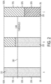
- Such static service allocation is illustrated in FIG. 2 .
- a link threshold 240 for guaranteed service may be pre-determined (corresponding approximately to 62.5% in this exemplary scenario).
- state 210 the full bandwidth is available (i.e. greater than the 62.5% threshold) for the services allocated on the link. Therefore, no problems are encountered.
- state 220 the link bandwidth has decreased to approximately 65% (still greater than the threshold) and some bandwidth is not available (35%). In this state, less bandwidth is made available to the best effort services (i.e. not guaranteed service) and best effort end-users can potentially experience a slower connection (i.e. service degradation). Guaranteed service end-users can still be provided service.
- the link bandwidth has decreased to a level where it is not possible to sustain the guaranteed services (i.e. less than 62.5%).
- the services compete for the same resources, they could potentially all experience service degradation or even a service break down. Since it is not possible to operate in this state, the link can be shut down.
- a command signal needs to be sent to all services to take an alternate route. Transmitting such a signal may not always be possible as bandwidth may not be available to cater for extra bandwidth needed by the service.
- circuitry configured to perform one or more described actions is used herein to refer to any such embodiment (i.e., one or more specialized circuits and/or one or more programmed processors).
- the invention can additionally be considered to be embodied entirely within any form of computer readable carrier, such as solid-state memory, magnetic disk, or optical disk containing an appropriate set of computer instructions that would cause a processor to carry out the techniques described herein.
- any such form of embodiments as described above may be referred to herein as "logic configured to” perform a described action, or alternatively as “logic that” performs a described action.
- the outcome of the static service allocation may be improved by establishing control over the services that should be sustained on a link during bandwidth decrease.
- Some of the services on the link can be blocked and redistributed to other paths through the network in some embodiments.
- the services on the link can even be blocked without redistribution in some embodiments.
- bandwidth may be freed to facilitate better support for the services still allocated on the link (or for those services sharing path with the blocked service).
- the redistributable service allocation according to exemplary embodiments can facilitate operation below the pre-determined threshold such as state 230 of FIG. 2 .
- a network is configured to redistribute the traffic to alternate paths
- the correlation in the bandwidth variation between the different links i.e. "original" and alternate
- Redistribution of traffic between links that experience the same (or similar) physical conditions may not provide same level of performance or resiliency as redistribution over links with diverse physical conditions.
- Load sharing methods may utilize several paths between nodes and can facilitate operation at lower bandwidths.
- the availability requirements on the guaranteed traffic per link can be reduced.
- Exemplary embodiments may be applicable to those variations that are too long to be buffered but not long enough to drive the dimensioning of the network.
- the redistribution of services has to be completed in a timely manner such that an end-user's quality of experience (QoE) is not affected or diminished.
- QoE quality of experience
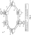
- Network 300 may include a plurality of nodes 310, 320, 330, 340, 350 and 360 (with corresponding switches 312, 322, 332, 342, 352 and 362).
- Network 300 may also include a plurality of links 370 between the nodes.
- two distribution functions 325 and 355 are included.
- Preconfigured service paths 380 and 390 may be setup between the service redistribution functions (via the links). The pre-configuration may take place during network dimensioning.
- the actual path used 380 (referred to as the "active" path for example) may be determined by the redistribution functions 325 and 355 through active monitoring of the connectivity over the paths 380 and 390. Paths that are not used, such as path 390, may be denoted as passive paths. Load sharing over multiple active paths between two service redistribution functions may also be facilitated according to exemplary embodiments.
- While the network of FIG. 3 depicts only one service, additional services can be deployed in a similar fashion. A link can then be traversed by multiple services.
- the variable bandwidth links may influence the redistribution functions by blocking/enabling services and, in effect, forcing a redistribution of those services.
- Exemplary embodiments provide redistribution per service over different paths in a topology consisting not only of primary and backup paths between two nodes, but also an arbitrary number of ingress and egress points. Multiple links may exist between one set of nodes (such as between nodes 310 and 320 for example). Multiple paths may exist between a set of nodes as well.
- Exemplary embodiments for achieving increased capacity and availability in networks with variable link bandwidth detect impairment in a link, communicate information about the impairment to other links and distribute the services from links with reduced bandwidth to other links having the bandwidth available for facilitating the service. Bandwidth requirement on the impaired links is throttled down to a level that can be accommodated by the reduced bandwidth.
- Impairment may be detected if the link level conditions indicate a need for relocation of service with a potential gain.
- Potential gain refers to the ability to use at least some of the available bandwidth (that has been reduced in a degraded link) as opposed to not being able to use any of the available bandwidth.
- Information about the impairment may be communicated for resolution. Signaling between nodes may be used to communicate the impairment information.
- the information that is communicated can include the reduced bandwidth value for example. For example, if a link is set up with 300 Mbps bandwidth and degradation leads to a bandwidth of 200 Mbps in the link, the reduced bandwidth value (i.e. 200 Mbps) can be communicated to the other nodes.
- the resolution may include redistributing services on the impaired links to links which have adequate bandwidth for sustaining the traffic. The changes in the network resulting from the impairment and redistribution can be communicated to the control plane or network management system.
- the detection of impairment includes finding network states that could be gained by a potential redistribution of services. For variable bandwidth networks, this includes having the ability to add services for transmission to links with available bandwidth.
- a link can be used by several services which may have different QoS requirements. Depending on those requirements and the pattern of the link bandwidth variation, the services can be affected in different ways. For links where the link speed varies in such a fashion that buffering alone can not contribute to service degradation, the service (that is affected by the degradation) may be redistributed to other paths through the network.
- Services that can be redistributed may be enabled with impairment detection for those links where bandwidth variation is dimensioned to occur.
- the impairment detection may include evaluating whether the service can be sustained on the link or it has to be moved to another link.
- Link degradation may be detected by utilizing performance parameters for monitoring signal quality.
- the link capacity may be signaled back to the node from which packets are sent over the link. Performance parameters are known and are used to determine packet loss, error rate, etc.
- the PHY mode of a link may be used to detect impairment and redistribution of a service.
- An evaluation of a buffer may also be made to determine if service redistribution is warranted (i.e. congestion may be evaluated on a link in deciding whether to redistribute a service).
- a priority scheme may be applied to determine the order of redistribution of the impaired services.
- the priority may be influenced by factors such as the current link bandwidth, the QoS requirements of the services, the service requirements for bandwidth etc.
- the link improves (i.e. the bandwidth increases to previously set levels for example), an evaluation of services that could be accommodated on the link may be triggered.
- the impairment detection functionality may be located in the network element attached to the variable link function where congestion detection is possible. This location may be at one or both ends of a link depending on whether symmetric or asymmetric traffic patterns are expected.
- the functionality for detecting impairment may be located at a network location that is different from a network location where the impairment may be resolved (by redistributing the impacted service for example). Therefore, the detected impairment (and its scope) has to be communicated to the location of the impairment resolution. This may be accomplished by letting network elements experiencing impairment actively block or drop service path monitoring messages. Dropping or blocking service path monitoring messages can signal link impairment. Such impairment can be signaled to the service resolution functionality.
- Per service path monitoring message is not limited to a particular protocol and may be implemented for Ethernet using Ethernet OAM such as CCM (Continuity Check Message) or other performance parameters as defined in ITU-T Recommendation Y.1731.
- Ethernet OAM such as CCM (Continuity Check Message) or other performance parameters as defined in ITU-T Recommendation Y.1731.
- MPLS/MPLS-TP OAM such as Hello in BDF (bidirectional forwarding detection) as defined by the IETF can be used. Communication of impairment in this manner is interoperable to already deployed networks and network elements.
- the service redistribution function can typically be pre-provisioned with at least two paths.
- the paths may be an active path 380 and a passive path 390 as illustrated in FIG. 3 .
- the alternative paths may be pre-defined during network provisioning for example. Passive paths are not entirely unutilized. They may be used for low priority traffic when not being used as active paths.
- Network planning, control plane and/or network management systems may control how the network responds to variations in link bandwidth.
- Network elements detecting impairment and the network elements implementing the redistribution function are synchronized according to exemplary embodiments. Since exemplary embodiments are implemented per service, deployments having more than two network entry/exists are supported without having to synchronize additional network elements. Service re-routing may be achieved without the need for communication among the edge nodes.
- a set of rules or conditions may be established for links. These rules may specify the action(s) to be taken in case of link degradation.
- the rules may, for example, specify that if bandwidth falls below a particular level in a link, then a service has to be redistributed to another link/path.
- the service that is to be redistributed, and the link to which it is to be redistributed, may also be specified.
- Rules that are specific to each node may be located at the physical layer for each node; rules for the network may be located at the control plane and/or the network management system (NMS).
- NMS network management system
- Different types of services may be affected differently when, on one hand, they run on variable bandwidth links and on the other hand, they are subjected to redistribution to a new path.
- Non-time critical services may handle variations in bandwidth better than real-time services (guaranteed service).
- the traffic may be buffered more extensively and since the service does not have a strict delivery deadline, a good QoE may be offered. Extensive buffering on real-time service, however, may degrade the user QoE.
- the link buffer may be used by the TCP AIMD (Additive Increase/Multiplicative Decrease) congestion avoidance mechanism to handle congestion and maintain a high TCP throughput.
- TCP AIMD Additional Increase/Multiplicative Decrease
- the contents of the buffer can be discarded. The switch and loss of packet(s) can disturb the TCP session and thus reduce the throughput compared to letting the buffer sustains the throughput.
- TCP flows might end up in a slow start phase. Due to the exponential traffic growth during slow start of several TCP flows, disturbance may also occur on the backup path.
- buffer build-up may not be an accurate indicator of service degradation.
- buffer build-up may be a good indication of the commencement of service degradation.
- variable link bandwidth networks may redistribute real-time services before redistributing best effort services.
- the timing requirements for real-time services are strict.
- Method 400 of FIG. 4 may include impairment detection at 410, impairment communication at 420 and impairment resolution at 430.
- Impairment communication may include communicating the impairment to other nodes.
- Impairment resolution may include redistribution of services.
- Node 500 may include an impairment detection module 510, a communication interface 520 and impairment resolution module 530.
- the functionality of modules 510 and 530 was described above.
- the communication interface 520 communicates the impairment detection to other nodes in the network and also facilitates communication between modules 510 and 530.
- As a result of service redistribution that is performed module 530 to resolve an impairment the bandwidth required by services running on the impaired link is reduced so that it does not exceed the available bandwidth.
- the interface 520 may be separated into two functional units, one for communication with the other nodes in the network and one for communication between the impairment detection module 510 and the impairment mitigation module 530.
- Interface 520 can communicate, to the other nodes, the bandwidth available after the impairment and the services running on the link used by the node. Interface 520 can also receive, from the other nodes, information about bandwidth available on links used by the other nodes and services running on those links.
- Modules 510, 520 and 530 can be implemented in one hardware block 540 or in node 500 as separate hardware modules. Traffic congestion may also be monitored on a link using a fixed or configurable threshold setting. The buffer may be monitored for example and if the information in the buffer exceeds a pre-determined threshold, some (or even all in some instances) of the traffic on that congested link can be redistributed to other links.
- Exemplary embodiments as described herein may conform to any technology performing connectivity verification over a set of alternate connections/paths. Therefore, several different realizations are possible. Some examples of these realizations are highlighted below.
- the method as described in exemplary embodiments may be implemented in MPLS-TP, IETF RFC 5921, with a 1:1 protection scheme using an active and a standby path.
- the service path may be mapped to either the transport LSP (Label Switched Path) or a PW (Pseudo Wire). Link bandwidth degradation events may then influence the MPLS-TP protection mechanisms to switch over to an alternate path.
- LSP Label Switched Path
- PW Pseudo Wire
- PBB-TE Provide Backbone Bridge Traffic Engineering
- IEEE 802.1Qay-2009 may implement path protection through a worker path and a protect path.
- Mapping for PBB-TE may be similar to that of MPLS-TP.
- an impaired link may trigger the blocking of BFD Hellos. The traffic or service associated with that route is then forced to take an alternate path.
- performance parameters on microwave links may be monitored. When degradation of these links reaches a threshold that is below a required level, the traffic on these microwave links may be distributed over other transmission links.
- a test signal (e.g. Section 7.7.2N. 173 1) may be used or Synthetic Frame Loss Measurement (SLM) as described in ITU-T recommendation Y.1731 to monitor the microwave links. If a determination is made that the links are degraded, the traffic may be throttled down on these links and consequently the bandwidth of these links is reduced accordingly. Link degradation may always imply activation of bandwidth reduction.
- SLM Synthetic Frame Loss Measurement
- the test signal can, for example, be a pseudo-random bit sequence (PRBS) of 2 31 - 1 or any other suitable test signal.
- PRBS pseudo-random bit sequence
- the test signal can be mapped into the OAM PDU as defined in Y.1731 and the bit errors are monitored on the links. If the errors exceed a threshold, these links can be declared as being degraded and the bandwidth is reduced and the services that are transported on these links can be distributed on other links that are not degraded or have bandwidth available for transporting the diverted services.
- a service redistribution method in accordance with exemplary embodiments may be described with reference to FIGs. 6(A) - 6(C) .
- a normal operating condition is illustrated in FIG. 6(A) .
- Service paths having a 300 Mbps bandwidth may be established between nodes 610 and 620. These paths may be designated as 630 and 640.
- Services S1 and S2 (having a 50 and 75 Mbps requirement respectively) may be assigned to path 630 and service S2 and S4 (having 90 and 40 Mbps requirement respectively) may be assigned to path 640.
- S1 may be a critical service such as voice service for example.
- S2, S3 and S4 may be less critical services such as video services or value-added services.
- the combined requirement for S1 and S2 is 125 Mbps which can be accommodated by path 630 in its normal state of 300 Mbps bandwidth.
- the combined requirement for S3 and S4 of 130 Mbps can be accommodated by path 640 in its normal state of 300 Mbps bandwidth.
- Service path 630 may include a plurality of tunnels 631, 633, 635 and 637 between a plurality of radio towers 632, 634 and 636 as illustrated. Each of the tunnels may have a 300 Mbps bandwidth.
- service path 640 may include tunnels 641, 643, 645 and 647 having a bandwidth of 300 Mbps between radio towers 642, 644 and 646.
- Service path 630 may experience degradation resulting in reduction to a bandwidth of 100 Mbps (in tunnel 635 in this example) and service path 640 may experience degradation resulting in reduction to a bandwidth of 200 Mbps (in tunnel 645 in this example) as illustrated in FIG. 6(B) .
- path 630 could accommodate one of S1 (50 Mbps), S2 (75 Mbps), S3 (90 Mbps) and S4 (40 Mbps) since each of these require less than the available bandwidth of 100 Mbps.
- Path 630 could also accommodate the combined requirements of S1 (50 Mbps) and S4 (40 Mbps) since their combined requirement (90 Mbps) is less than the available bandwidth of 100 Mbps.
- Path 640 with its current available bandwidth of 200 Mbps can accommodate each of the following individual and combined services: S1, S2, S3, S4, S1/S2, S1/S3, S1/S4, S2/S3, S2/S4, S3/S4, S1/S2/S4 and S1/S3/S4.
- the services can be redistributed.
- service S2 can be switched to path 640 and service S4 can be switched to path 630.
- services S1 and S4 are carried by path 630 and services S2 and S3 are carried by path 640.
- the combined requirements of S1 and S4 (90 Mbps) can be accommodated by path 630 even in its degraded state (with 100 Mbps).
- the combined requirements of S2 and S3 (165 Mbps) can be accommodated by path 640 in its degraded state (200 Mbps).
- Services S1 and S2 can be grouped over one path (630) as illustrated in FIGS. 6(A) .
- Services S3 and S4 can be grouped over another path (640). That is, multiple services can be grouped for transmission over one path.
- Performance monitoring of the microwave links can be carried out, but not limited, by the following possible methods: (i) A test signal may be sent as defined in ITU Recommendation Y.1731 for monitoring errors and declaring the link as being degraded at various threshold values; and (ii) Synthetic Frame Loss (SLM) measurement as defined in the latest Y.1731 may be used.
- SLM Synthetic Frame Loss
- a message is sent to each end of the path indicating the current maximum bandwidth that can be utilized on the path as well as communicating with intermediate points along the path.
- the current maximum bandwidth of the path cannot be exceeded as a result of redistributing the services.
- messages may be exchanged or sent between the endpoints of the paths and/or intermediate points along the path to negotiate the redistribution of the services on the path.
- Ring 700 includes nodes 710, 720, 730 and 740 (with corresponding switches 712, 722, 832 and 742) and links L1, L2, L3 and L4 between the nodes.
- the services traversing the ring 700 from nodes 710, 720 and 740 are aggregated into node 730.
- Each of the nodes 710, 720 and 740 can have multiple service redistribution functions associated therewith. These functions are designated as 717, 727 and 747 respectively.
- redistribution functions may be configured over (active) service paths 715, 705/725 and 745 to node 730.
- the passive paths (not illustrated) can be routed in the opposite direction of the associated active path.
- Node 730 may detect impairments on paths 705 and/or 715. According to exemplary embodiments, parts of the services to nodes 710 and 720 (from node 730) traversing paths 715 and 705 may be blocked. The services can then be redistributed on the (currently) passive paths associated (in opposite direction) with paths 745, 725 and 705 from node 730 to nodes 740, 720 and 710 respectively.
- Network 800 includes nodes 810, 820, 830 and 840 (with corresponding switches 812, 822, 832 and 842) and links L1, L2 and L3 between the nodes. As with the aggregation ring 700 of FIG. 7 , some of the nodes can have multiple service redistribution functions. In network 800, nodes 810 and 820 have multiple service redistribution functions associated therewith. These functions are designated as 818 and 828 respectively.
- nodes 830 and 840 provide access to another connectivity domain 850.
- the service paths 815 and 825 i.e. active service paths
- This information i.e. whether they offer connectivity
- No direct communication path is needed between 830 and 840 to exchange information about the states of the links.
- active service path 815 between nodes 810 and 830 is degraded, then the passive service path 816 between nodes 810 and 840 is used to send service from node 810 to node 840.
- active service path 825 between nodes 820 and 840 is degraded, then the passive service path 826 between 820 and 830 is used to send service from node 820 to node 830.
- it is not impossible to use one path for both services if another path is degraded as long as the non-degraded path provides the required bandwidth.
- the load-sharing and redistribution functionality in the necklace network 800 is similar to that of ring network 700.
- the impairment signaling is performed by blocking the service paths. Therefore, the load-sharing method described with reference to network 800 does not introduce any new information that needs to be synchronized between the redistribution functions on nodes 830 and 840. Protections schemes offering one active path already have mechanisms for synchronizing the active/passive path state.
- Links can be used continuously even with degraded conditions (i.e. at a reduced bandwidth). Links can be used in microwave networks or other point to point communications. Exemplary embodiments as described for handling variable bandwidth networks can be implemented utilizing existing technologies.
- Service re-routing is facilitated over complex topologies with several ingress and egress points triggered by impairment conditions on variable bandwidth links.
- Information about the impairment condition is communicated to a limited set of network elements and network level synchronization is not used.
- the response time for addressing impairment conditions is short, typically less then 50 ms. Exemplary embodiments can leverage existing technologies.
Landscapes
- Engineering & Computer Science (AREA)
- Computer Networks & Wireless Communication (AREA)
- Signal Processing (AREA)
- Data Exchanges In Wide-Area Networks (AREA)
Claims (13)
- Procédé de d'ajustement de bande passante dans un réseau de communication comprenant une pluralité de noeuds connectés sur plusieurs liaisons et ayant une pluralité de services exécutés sur les liaisons, le procédé comprenant les étapes consistant àdétecter (410) une dégradation d'une liaison en utilisant des paramètres de performance pour surveiller la qualité de signal, la dégradation invoquant une réduction de la bande passante disponible pour les services exécutés sur la liaison ;communiquer (420) des informations sur la dégradation ; etprovoquer une redistribution (430) de services entre la liaison dégradée et au moins une autre liaison, la redistribution (430) comprenant le maintien d'un service de haute priorité sur la liaison dégradée, si la liaison dégradée peut supporter le service de haute priorité.
- Procédé selon la revendication 1, dans lequel la redistribution (430) s'effectue sur une base par service.
- Procédé selon la revendication 1, dans lequel la redistribution (430) comprend la commutation d'un service à faible priorité de la liaison dégradée vers une autre liaison.
- Procédé selon la revendication 1, dans lequel la redistribution (430) de services comprend :
l'échange de services entre la liaison dégradée et au moins une liaison supplémentaire. - Procédé selon la revendication 4, dans lequel l'échange de services comprend :
le routage d'un service de la liaison dégradée vers une autre liaison et le routage d'un service de l'autre liaison vers la liaison dégradée. - Noeud (500) pour un réseau de communication, le réseau de communication comprenant une pluralité de noeuds connectés sur plusieurs liaisons et ayant une pluralité de services exécutés sur les liaisons, le noeud comprenant :un module de détection de dégradation (510) pour détecter une dégradation dans une liaison en utilisant des paramètres de performance pour surveiller la qualité de signal, la liaison étant utilisée par la pluralité de services, la dégradation invoquant une réduction de la bande passante disponible pour les services exécutés sur la liaison ;une interface de communication (520) pour communiquer des informations sur la dégradation ; etun module de résolution de dégradation (530) pour provoquer une redistribution de services entre la liaison dégradée et au moins une autre liaison, la redistribution comprenant le maintien d'un service de haute priorité sur la liaison dégradée, si la liaison dégradée peut supporter le service de haute priorité.
- Noeud (500) selon la revendication 6, dans lequel l'interface de communication (520) est opérationnelle pour fournir une communication entre le module de détection de dégradation (510) et le module de résolution de dégradation (530) .
- Noeud (500) selon la revendication 6, dans lequel l'interface de communication (520) est opérationnelle pour communiquer des informations sur les services exécutés sur la liaison dégradée.
- Noeud (500) selon la revendication 6, dans lequel l'interface de communication (520) est opérationnelle pour recevoir des informations de bande passante disponible provenant des autres noeuds du réseau, les informations de bande passante disponible correspondant aux liaisons utilisées par les autres noeuds.
- Procédé d'ajustement de bande passante dans un réseau de communication comprenant une pluralité de noeuds connectés sur plusieurs liaisons et ayant une pluralité de services exécutés sur les liaisons, le procédé comprenant les étapes consistant àobtenir des informations sur une dégradation détectée d'une liaison, la dégradation étant détectée en utilisant des paramètres de performance pour surveiller la qualité de signal, la dégradation invoquant une réduction de la bande passante disponible pour les services exécutés sur la liaison ;provoquer une redistribution (430) des services exécutés sur la liaison en réponse aux informations obtenues, les services étant redistribués entre la liaison dégradée et au moins une autre liaison, la redistribution (430) comprenant le maintien d'un service de haute priorité sur la liaison dégradée, si la liaison dégradée peut supporter le service de haute priorité.
- Procédé selon la revendication 10, dans lequel la redistribution (430) s'effectue sur une base par service.
- Procédé selon la revendication 10, dans lequel la redistribution (430) comprend la commutation d'un service à faible priorité de la liaison dégradée vers une autre liaison.
- Module de résolution de dégradation pour un noeud d'un réseau de communication, le réseau de communication comprenant une pluralité de noeuds connectés sur plusieurs liaisons et ayant une pluralité de services exécutés sur les liaisons, le module de résolution de dégradation étant configuré pour :obtenir des informations sur une dégradation détectée d'une liaison, la dégradation étant détectée en utilisant des paramètres de performance pour surveiller la qualité de signal et la liaison étant utilisée par la pluralité de services, la dégradation invoquant une réduction de la bande passante disponible pour les services exécutés sur la liaison ;provoquer une redistribution des services exécutés sur la liaison en réponse aux informations obtenues, les services étant redistribués entre la liaison dégradée et au moins une autre liaison, la redistribution comprenant le maintien d'un service de haute priorité sur la liaison dégradée, si la liaison dégradée peut supporter le service de haute priorité.
Applications Claiming Priority (4)
| Application Number | Priority Date | Filing Date | Title |
|---|---|---|---|
| US201161560187P | 2011-11-15 | 2011-11-15 | |
| US13/493,039 US8953440B2 (en) | 2011-11-15 | 2012-06-11 | Dynamic bandwidth adjustment in packet transport network |
| EP12786967.5A EP2742657B1 (fr) | 2011-11-15 | 2012-11-09 | Ajustement dynamique de bande passante dans un réseau de transport par paquets |
| PCT/EP2012/072252 WO2013072253A1 (fr) | 2011-11-15 | 2012-11-09 | Ajustement dynamique de bande passante dans un réseau de transport par paquets |
Related Parent Applications (2)
| Application Number | Title | Priority Date | Filing Date |
|---|---|---|---|
| EP12786967.5A Division EP2742657B1 (fr) | 2011-11-15 | 2012-11-09 | Ajustement dynamique de bande passante dans un réseau de transport par paquets |
| EP12786967.5A Division-Into EP2742657B1 (fr) | 2011-11-15 | 2012-11-09 | Ajustement dynamique de bande passante dans un réseau de transport par paquets |
Publications (3)
| Publication Number | Publication Date |
|---|---|
| EP3208978A1 EP3208978A1 (fr) | 2017-08-23 |
| EP3208978B1 true EP3208978B1 (fr) | 2025-01-01 |
| EP3208978C0 EP3208978C0 (fr) | 2025-01-01 |
Family
ID=47178686
Family Applications (2)
| Application Number | Title | Priority Date | Filing Date |
|---|---|---|---|
| EP17164495.8A Active EP3208978B1 (fr) | 2011-11-15 | 2012-11-09 | Ajustement dynamique de bande passante dans un reseau de transport par paquets |
| EP12786967.5A Active EP2742657B1 (fr) | 2011-11-15 | 2012-11-09 | Ajustement dynamique de bande passante dans un réseau de transport par paquets |
Family Applications After (1)
| Application Number | Title | Priority Date | Filing Date |
|---|---|---|---|
| EP12786967.5A Active EP2742657B1 (fr) | 2011-11-15 | 2012-11-09 | Ajustement dynamique de bande passante dans un réseau de transport par paquets |
Country Status (4)
| Country | Link |
|---|---|
| US (3) | US8953440B2 (fr) |
| EP (2) | EP3208978B1 (fr) |
| CN (1) | CN103931145B (fr) |
| WO (1) | WO2013072253A1 (fr) |
Families Citing this family (17)
| Publication number | Priority date | Publication date | Assignee | Title |
|---|---|---|---|---|
| US8964553B2 (en) * | 2011-12-13 | 2015-02-24 | Ixia | Network impairment unit with bandwidth-constrained packet duplication |
| US9780964B1 (en) * | 2012-01-23 | 2017-10-03 | Cisco Technology, Inc. | System and method for ring protection switching over adaptive modulation microwave links |
| US9025435B2 (en) * | 2012-10-18 | 2015-05-05 | Ciena Corporation | Optimized seam allocation in an ethernet ring network |
| US9161259B2 (en) | 2013-03-20 | 2015-10-13 | Cisco Technology, Inc. | System and method for layer 3 ring protection with adaptive bandwidth microwave links in a network environment |
| US9392526B2 (en) * | 2013-05-28 | 2016-07-12 | Cisco Technology, Inc. | Protection against fading in a network ring |
| CN103973490B (zh) * | 2014-05-05 | 2016-03-30 | 江苏鑫软图无线技术股份有限公司 | 一种基于数据挖掘的ptn传输带宽自适应调整方法 |
| US10594554B2 (en) * | 2014-05-15 | 2020-03-17 | Applied Invention, Llc | Method and apparatus for communication system upgrade via phased adoption |
| US11182185B2 (en) * | 2014-06-27 | 2021-11-23 | Vmware, Inc. | Network-based signaling to control virtual machine placement |
| US9602374B2 (en) * | 2014-07-21 | 2017-03-21 | Ciena Corporation | Systems and methods for collecting and analyzing data to determine link quality and stability in layer two networks |
| KR101630519B1 (ko) * | 2014-08-12 | 2016-06-24 | 삼성에스디에스 주식회사 | 데이터 트래픽의 전송을 제어하는 장치 및 방법 |
| CN106161276B (zh) * | 2015-04-03 | 2020-01-31 | 华为技术有限公司 | 一种调整网络流量的方法和装置 |
| US10084675B2 (en) * | 2016-04-07 | 2018-09-25 | International Business Machines Corporation | Monitoring connections for data communications |
| US10827001B2 (en) | 2016-07-27 | 2020-11-03 | International Business Machines Corporation | Managing connections for data communications |
| US10742747B2 (en) | 2017-07-06 | 2020-08-11 | International Business Machines Corporation | Managing connections for data communications following socket failure |
| CN109995633B (zh) * | 2017-12-29 | 2021-10-01 | 华为技术有限公司 | 一种芯片及相关设备 |
| US10992567B2 (en) * | 2018-11-21 | 2021-04-27 | Ciena Corporation | Traffic engineering attribute for avoiding packet paths with signal degrade |
| US12531776B2 (en) * | 2022-07-15 | 2026-01-20 | Cisco Technology, Inc. | Extending active measurement protocol with OAM channel |
Family Cites Families (10)
| Publication number | Priority date | Publication date | Assignee | Title |
|---|---|---|---|---|
| EP1096712A3 (fr) * | 1999-10-29 | 2005-09-07 | Nippon Telegraph and Telephone Corporation | Réseau de chemins et procédé d'utilisation de réseau de chemins mettant en oeuvre la conversion du chemin de protection en chemin actif |
| US7545755B2 (en) * | 2000-03-03 | 2009-06-09 | Adtran Inc. | Routing switch detecting change in session identifier before reconfiguring routing table |
| JP3983042B2 (ja) | 2000-12-07 | 2007-09-26 | アルカテル・カナダ・インコーポレイテツド | ソースルーティングシグナリングプロトコル通信ネットワークにおけるコールブロッキングトリガトポロジ更新のためのシステムおよび方法 |
| DE10304347A1 (de) * | 2003-02-03 | 2004-08-19 | Marconi Communications Gmbh | Kommunikationsnetz und Verfahren zur Datenübertragung in einem Kommunikationsnetz |
| US8184549B2 (en) | 2006-06-30 | 2012-05-22 | Embarq Holdings Company, LLP | System and method for selecting network egress |
| CN101232427A (zh) * | 2007-01-23 | 2008-07-30 | 华为技术有限公司 | 一种以太网环保护方法及装置 |
| US8059540B2 (en) * | 2007-05-25 | 2011-11-15 | Futurewei Technologies, Inc. | Policy based and link utilization triggered congestion control |
| JP2009231906A (ja) * | 2008-03-19 | 2009-10-08 | Nec Corp | データ伝送システム、伝送装置、およびプロテクション制御方法 |
| US8619583B2 (en) * | 2010-01-06 | 2013-12-31 | Futurewei Technologies, Inc. | Ingress node controlled path impairment protocol |
| US20110261695A1 (en) | 2010-04-23 | 2011-10-27 | Xiaoming Zhao | System and method for network congestion control |
-
2012
- 2012-06-11 US US13/493,039 patent/US8953440B2/en active Active
- 2012-11-09 WO PCT/EP2012/072252 patent/WO2013072253A1/fr not_active Ceased
- 2012-11-09 EP EP17164495.8A patent/EP3208978B1/fr active Active
- 2012-11-09 CN CN201280056206.5A patent/CN103931145B/zh active Active
- 2012-11-09 EP EP12786967.5A patent/EP2742657B1/fr active Active
-
2014
- 2014-12-23 US US14/581,017 patent/US9264345B2/en active Active
-
2016
- 2016-01-19 US US15/000,366 patent/US9485181B2/en active Active
Also Published As
| Publication number | Publication date |
|---|---|
| US20160142319A1 (en) | 2016-05-19 |
| US9485181B2 (en) | 2016-11-01 |
| CN103931145A (zh) | 2014-07-16 |
| EP2742657A1 (fr) | 2014-06-18 |
| EP2742657B1 (fr) | 2017-05-10 |
| US20150109906A1 (en) | 2015-04-23 |
| WO2013072253A1 (fr) | 2013-05-23 |
| US9264345B2 (en) | 2016-02-16 |
| US20130148494A1 (en) | 2013-06-13 |
| EP3208978A1 (fr) | 2017-08-23 |
| CN103931145B (zh) | 2018-07-24 |
| EP3208978C0 (fr) | 2025-01-01 |
| US8953440B2 (en) | 2015-02-10 |
Similar Documents
| Publication | Publication Date | Title |
|---|---|---|
| EP2742657B1 (fr) | Ajustement dynamique de bande passante dans un réseau de transport par paquets | |
| US9634925B2 (en) | Technique for network routing | |
| US9451500B2 (en) | Conditional routing technique | |
| JP5453535B2 (ja) | 自動保護切替方法およびデバイス | |
| US8139479B1 (en) | Health probing detection and enhancement for traffic engineering label switched paths | |
| CN101577661B (zh) | 一种路径切换的方法和设备 | |
| EP2025096B1 (fr) | Traitement hiérarchisé et propagation d'incidents partiels dans un réseau à commutation de paquets | |
| US8897140B1 (en) | Congestion managed traffic engineering services in multiprotocol label switching and generalized multiprotocol label switching networks | |
| US20090296572A1 (en) | Tunnel establishing method, network node device and network system | |
| EP2475131B1 (fr) | Procédé de notification d informations de largeur de bande, procédé de traitement de service, noeud de réseau et système de communication | |
| CN101874388A (zh) | 在节点之间具有多个路径的网络和用于这样的网络的节点 | |
| KR20140088206A (ko) | 네트워크 측정 트리거들을 사용하는 서비스 보장 | |
| US12010017B2 (en) | Routing online application traffic based on path fate sharing metrics | |
| Srikitja et al. | On providing survivable QoS services in the next generation Internet | |
| Suhaimy et al. | Analysis of MPLS-TP network for different applications | |
| EP2781064B1 (fr) | Technique de routage conditionnel | |
| US9800512B2 (en) | Method and system for prioritising traffic flows | |
| Kanagavelu et al. | A Pro-Active and Adaptive Mechanism | |
| EP2030379A1 (fr) | Restauration efficace de connexions dans des réseaux de communication à plan de commande ip | |
| Francisco et al. | A previous study on Dynamic Alternative Routing with local protection paths in MPLS networks |
Legal Events
| Date | Code | Title | Description |
|---|---|---|---|
| PUAI | Public reference made under article 153(3) epc to a published international application that has entered the european phase |
Free format text: ORIGINAL CODE: 0009012 |
|
| STAA | Information on the status of an ep patent application or granted ep patent |
Free format text: STATUS: REQUEST FOR EXAMINATION WAS MADE |
|
| 17P | Request for examination filed |
Effective date: 20170403 |
|
| AC | Divisional application: reference to earlier application |
Ref document number: 2742657 Country of ref document: EP Kind code of ref document: P |
|
| AK | Designated contracting states |
Kind code of ref document: A1 Designated state(s): AL AT BE BG CH CY CZ DE DK EE ES FI FR GB GR HR HU IE IS IT LI LT LU LV MC MK MT NL NO PL PT RO RS SE SI SK SM TR |
|
| STAA | Information on the status of an ep patent application or granted ep patent |
Free format text: STATUS: EXAMINATION IS IN PROGRESS |
|
| 17Q | First examination report despatched |
Effective date: 20180803 |
|
| REG | Reference to a national code |
Ref country code: DE Ref legal event code: R079 Ref document number: 602012081298 Country of ref document: DE Free format text: PREVIOUS MAIN CLASS: H04L0012700000 Ipc: H04L0045125000 |
|
| GRAP | Despatch of communication of intention to grant a patent |
Free format text: ORIGINAL CODE: EPIDOSNIGR1 |
|
| STAA | Information on the status of an ep patent application or granted ep patent |
Free format text: STATUS: GRANT OF PATENT IS INTENDED |
|
| INTG | Intention to grant announced |
Effective date: 20240705 |
|
| RIC1 | Information provided on ipc code assigned before grant |
Ipc: H04L 47/762 20220101ALI20240624BHEP Ipc: H04L 47/125 20220101ALI20240624BHEP Ipc: H04L 47/74 20220101ALI20240624BHEP Ipc: H04L 45/00 20220101ALI20240624BHEP Ipc: H04L 45/125 20220101AFI20240624BHEP |
|
| GRAS | Grant fee paid |
Free format text: ORIGINAL CODE: EPIDOSNIGR3 |
|
| GRAA | (expected) grant |
Free format text: ORIGINAL CODE: 0009210 |
|
| STAA | Information on the status of an ep patent application or granted ep patent |
Free format text: STATUS: THE PATENT HAS BEEN GRANTED |
|
| AC | Divisional application: reference to earlier application |
Ref document number: 2742657 Country of ref document: EP Kind code of ref document: P |
|
| AK | Designated contracting states |
Kind code of ref document: B1 Designated state(s): AL AT BE BG CH CY CZ DE DK EE ES FI FR GB GR HR HU IE IS IT LI LT LU LV MC MK MT NL NO PL PT RO RS SE SI SK SM TR |
|
| REG | Reference to a national code |
Ref country code: GB Ref legal event code: FG4D |
|
| REG | Reference to a national code |
Ref country code: CH Ref legal event code: EP |
|
| REG | Reference to a national code |
Ref country code: DE Ref legal event code: R096 Ref document number: 602012081298 Country of ref document: DE |
|
| REG | Reference to a national code |
Ref country code: IE Ref legal event code: FG4D |
|
| U01 | Request for unitary effect filed |
Effective date: 20250203 |
|
| U07 | Unitary effect registered |
Designated state(s): AT BE BG DE DK EE FI FR IT LT LU LV MT NL PT RO SE SI Effective date: 20250207 |
|
| PG25 | Lapsed in a contracting state [announced via postgrant information from national office to epo] |
Ref country code: PL Free format text: LAPSE BECAUSE OF FAILURE TO SUBMIT A TRANSLATION OF THE DESCRIPTION OR TO PAY THE FEE WITHIN THE PRESCRIBED TIME-LIMIT Effective date: 20250101 |
|
| PG25 | Lapsed in a contracting state [announced via postgrant information from national office to epo] |
Ref country code: ES Free format text: LAPSE BECAUSE OF FAILURE TO SUBMIT A TRANSLATION OF THE DESCRIPTION OR TO PAY THE FEE WITHIN THE PRESCRIBED TIME-LIMIT Effective date: 20250101 |
|
| PG25 | Lapsed in a contracting state [announced via postgrant information from national office to epo] |
Ref country code: NO Free format text: LAPSE BECAUSE OF FAILURE TO SUBMIT A TRANSLATION OF THE DESCRIPTION OR TO PAY THE FEE WITHIN THE PRESCRIBED TIME-LIMIT Effective date: 20250401 Ref country code: IS Free format text: LAPSE BECAUSE OF FAILURE TO SUBMIT A TRANSLATION OF THE DESCRIPTION OR TO PAY THE FEE WITHIN THE PRESCRIBED TIME-LIMIT Effective date: 20250501 |
|
| PG25 | Lapsed in a contracting state [announced via postgrant information from national office to epo] |
Ref country code: HR Free format text: LAPSE BECAUSE OF FAILURE TO SUBMIT A TRANSLATION OF THE DESCRIPTION OR TO PAY THE FEE WITHIN THE PRESCRIBED TIME-LIMIT Effective date: 20250101 |
|
| PG25 | Lapsed in a contracting state [announced via postgrant information from national office to epo] |
Ref country code: GR Free format text: LAPSE BECAUSE OF FAILURE TO SUBMIT A TRANSLATION OF THE DESCRIPTION OR TO PAY THE FEE WITHIN THE PRESCRIBED TIME-LIMIT Effective date: 20250402 |
|
| PG25 | Lapsed in a contracting state [announced via postgrant information from national office to epo] |
Ref country code: CZ Free format text: LAPSE BECAUSE OF FAILURE TO SUBMIT A TRANSLATION OF THE DESCRIPTION OR TO PAY THE FEE WITHIN THE PRESCRIBED TIME-LIMIT Effective date: 20250101 |
|
| PG25 | Lapsed in a contracting state [announced via postgrant information from national office to epo] |
Ref country code: SM Free format text: LAPSE BECAUSE OF FAILURE TO SUBMIT A TRANSLATION OF THE DESCRIPTION OR TO PAY THE FEE WITHIN THE PRESCRIBED TIME-LIMIT Effective date: 20250101 |
|
| PG25 | Lapsed in a contracting state [announced via postgrant information from national office to epo] |
Ref country code: SK Free format text: LAPSE BECAUSE OF FAILURE TO SUBMIT A TRANSLATION OF THE DESCRIPTION OR TO PAY THE FEE WITHIN THE PRESCRIBED TIME-LIMIT Effective date: 20250101 |
|
| PLBE | No opposition filed within time limit |
Free format text: ORIGINAL CODE: 0009261 |
|
| STAA | Information on the status of an ep patent application or granted ep patent |
Free format text: STATUS: NO OPPOSITION FILED WITHIN TIME LIMIT |
|
| 26N | No opposition filed |
Effective date: 20251002 |
|
| U20 | Renewal fee for the european patent with unitary effect paid |
Year of fee payment: 14 Effective date: 20251126 |
|
| PGFP | Annual fee paid to national office [announced via postgrant information from national office to epo] |
Ref country code: GB Payment date: 20251127 Year of fee payment: 14 |