EP3209094B1 - Gargerät - Google Patents
Gargerät Download PDFInfo
- Publication number
- EP3209094B1 EP3209094B1 EP17152624.7A EP17152624A EP3209094B1 EP 3209094 B1 EP3209094 B1 EP 3209094B1 EP 17152624 A EP17152624 A EP 17152624A EP 3209094 B1 EP3209094 B1 EP 3209094B1
- Authority
- EP
- European Patent Office
- Prior art keywords
- cooking
- appliance
- perforated plates
- cooking chamber
- openings
- Prior art date
- Legal status (The legal status is an assumption and is not a legal conclusion. Google has not performed a legal analysis and makes no representation as to the accuracy of the status listed.)
- Active
Links
Images


Classifications
-
- H—ELECTRICITY
- H05—ELECTRIC TECHNIQUES NOT OTHERWISE PROVIDED FOR
- H05B—ELECTRIC HEATING; ELECTRIC LIGHT SOURCES NOT OTHERWISE PROVIDED FOR; CIRCUIT ARRANGEMENTS FOR ELECTRIC LIGHT SOURCES, IN GENERAL
- H05B6/00—Heating by electric, magnetic or electromagnetic fields
- H05B6/64—Heating using microwaves
- H05B6/6402—Aspects relating to the microwave cavity
-
- H—ELECTRICITY
- H05—ELECTRIC TECHNIQUES NOT OTHERWISE PROVIDED FOR
- H05B—ELECTRIC HEATING; ELECTRIC LIGHT SOURCES NOT OTHERWISE PROVIDED FOR; CIRCUIT ARRANGEMENTS FOR ELECTRIC LIGHT SOURCES, IN GENERAL
- H05B6/00—Heating by electric, magnetic or electromagnetic fields
- H05B6/64—Heating using microwaves
- H05B6/647—Aspects related to microwave heating combined with other heating techniques
-
- H—ELECTRICITY
- H05—ELECTRIC TECHNIQUES NOT OTHERWISE PROVIDED FOR
- H05B—ELECTRIC HEATING; ELECTRIC LIGHT SOURCES NOT OTHERWISE PROVIDED FOR; CIRCUIT ARRANGEMENTS FOR ELECTRIC LIGHT SOURCES, IN GENERAL
- H05B6/00—Heating by electric, magnetic or electromagnetic fields
- H05B6/64—Heating using microwaves
- H05B6/76—Prevention of microwave leakage, e.g. door sealings
Definitions
- the present invention relates to a cooking device with at least one cooking space and at least one high-frequency generator for the dielectric heating of food in the cooking space.
- the cooking space is limited by at least one lockable door and at least one cooking space wall.
- the cooking space is connected via at least one passage opening to at least one device component which is arranged at least partially outside the cooking space.
- the cooking chamber opening is generally closed with a door which essentially does not transmit high-frequency radiation.
- the cooking chamber is usually shielded by its walls. These walls are regularly made of sheet metal and therefore offer suitable shielding.
- the cooking chamber for hot air operation must have corresponding openings through which the hot air can be blown in.
- the hot air heating source must also have a connection to the surroundings of the device through which the air to be heated can be sucked in. Shielding a cooking chamber with such a hot air heating source is therefore often very complex and costly.
- cooking devices have become known in which the shaft or the openings of the hot-air motor are sealed at great expense.
- Cooking devices have also become known in which the hot air device is surrounded by elaborately constructed shielding plates.
- the known shields of such cooking devices generally function reliably, but are associated with a high level of structural complexity and therefore represent a cost-intensive production step.
- Designs of cooking devices of a known type are, for example, in JP 2004 278895A , JP S 60 105835 and or EP 2 520 133 B1 disclosed.
- the cooking device has at least one cooking space and at least one high-frequency generator for the dielectric heating of food in the cooking space.
- the cooking space is limited by at least one lockable door and at least one cooking space wall.
- the cooking space is connected via at least one passage opening to at least one device component which is arranged at least partially outside the cooking space.
- At least one shielding device against the emission of high-frequency radiation from the cooking space is assigned to the cooking space.
- the device component is arranged outside the shielding device.
- the shielding device comprises at least one shielding unit.
- the shielding unit is arranged at least in the area of the passage opening.
- the shielding unit comprises at least two perforated sheets.
- the perforated sheets are arranged in an at least two-layer arrangement.
- the perforated plates are spaced apart to form an intermediate space.
- the perforated sheets run at least in sections between the cooking space and the appliance component.
- the cooking device according to the invention has many advantages.
- a considerable advantage is that the device component is arranged outside the shielding device. This means that there is no need for complex and costly shielding, which would otherwise have to be arranged around the parts of the appliance component which extend from outside into the cooking space.
- the shielding device comprises at least one shielding unit with at least two perforated plates.
- the perforated plates enable the device component arranged outside the shielding device to be connected to the cooking space. For example, hot air can be blown into the cooking space through a perforated plate from a hot air heating source arranged outside the shield.
- the formation of a space between the perforated plates also provides a particularly effective shield against the escape of high-frequency radiation.
- the device component is arranged completely on one side of the shielding device, which is shielded from the high-frequency radiation in the cooking space.
- the device component does not run through the perforated plates.
- the shielding unit particularly preferably comprises two perforated plates, so that a double-layer arrangement results.
- the perforated sheets are preferably made of a steel sheet and / or another metal sheet.
- high-frequency generator is understood to mean all the devices necessary for generating the high-frequency radiation and for transmitting the high-frequency radiation into the cooking space.
- the perforated plates each have a large number of through openings.
- the intermediate space is connected to the cooking space and the appliance component through the through openings.
- the perforated plates preferably have a large number of bores. Perforated sheets can also be used.
- the through openings in particular have a maximum passage width.
- the passage openings preferably have a maximum passage width of one tenth of the wavelength of the electromagnetic radiation provided for the dielectric heating of the food.
- the maximum transmission width is less than 1/20 and preferably less than 1/50 of the wavelength used.
- the maximum transmission width can also be less than 1/100 of the wavelength used.
- the maximum passage width of the through openings is preferably selected such that, on the one hand, effective and reliable shielding can be ensured and, on the other hand, sufficient permeability is available for the connection between the cooking space and the appliance component.
- the through openings are in particular round.
- the maximum passage width then preferably corresponds to the diameter of the passage opening. It is possible that the through openings also have other shapes and are, for example, oval.
- the through openings of the adjacent perforated plates are arranged at least partially offset from one another.
- Such an offset arrangement provides improved shielding.
- the through openings are preferably offset such that there is no alignment line which runs through the through openings of both perforated plates.
- the through openings it is also possible for the through openings to be arranged at least partially and in particular completely one behind the other. Such an arrangement offers improved permeability for the connection between the appliance component and the cooking space.
- the through openings are particularly suitable and designed to allow an air flow and / or steam flow intended for cooking to pass between the appliance component and the cooking space.
- the through openings are particularly preferably suitable and designed to serve as a hot air passage for a hot air device located behind the shielding unit. It is also possible that the through openings are suitable and designed to allow vapors and / or light provided for illuminating the cooking space to pass between the appliance component and the cooking space.
- the through openings cover, for example, a lamp opening or a catalyst device in the cooking space.
- the perforated plates in the region of the intermediate space are preferably at a distance from one another which is greater than their thickness.
- a distance dimensioned in this way can compensate particularly well for any thermal expansion which occurs during operation of the cooking appliance.
- the distance between the perforated plates is several times greater than their thickness.
- the distance is more than 1 mm and in particular more than 2 mm and preferably more than 4 mm.
- the distance between the perforated plates is less than 10 mm and preferably less than 6 mm. Distances with such dimensions are sufficient to compensate for the thermal expansion and still require little installation space.
- the thickness of the perforated sheets is in particular between 0.1 mm and 2 mm. A lower or greater thickness of the perforated plates is also possible.
- At least one of the perforated plates comprises at least one bead which extends into the intermediate space up to the adjacent perforated plate.
- a strut and / or a reinforcing plate can also be provided for this purpose.
- the intermediate space is preferably at least partially delimited by at least one joining section.
- the joining section connects the perforated plates with each other.
- the joining section comprises at least one material connection of the perforated plates to one another.
- the joining section is preferably designed as a welded connection.
- Such a joining section enables a permanent connection of the perforated plates, which is suitable for shielding against high-frequency radiation.
- the joining section is designed to be electrically conductive. Particularly preferably, no through opening is provided in the joining section. In the area of the joining section, the perforated plates are connected to one another in particular without gaps. This can cause leakage of High-frequency radiation can be avoided particularly effectively.
- at least one further component is arranged in the joining section. For example, a further wall or a profile element is arranged between the perforated sheets.
- connection section comprises in particular at least one material connection of at least one of the perforated plates to the cooking chamber wall. This enables a stable and well-shielded connection of the perforated plates to other cooking space walls.
- the integral connection in the connection section is preferably a welded connection.
- the shielding unit preferably extends only in the region of the passage opening.
- Continuous cooking space walls are preferably provided outside the passage opening.
- the cooking space wall is designed, for example, as a muffle or part of a muffle. It is possible that in addition to the perforated sheets, at least one cooking chamber wall is also arranged in the area of the shielding unit. It is possible that the connection section comprises at least one non-integral connection of at least one of the perforated plates to the cooking chamber wall.
- the joining section and / or the connecting section are designed to be enamelable. At least the joining section and / or the connecting section is preferably coated with at least one enamel coating. All cooking chamber walls and shielding units are particularly preferably designed to be enamelable and / or coated with an enamel coating. Such an embodiment enables the entire system of cooking space walls and shielding units to be given an enamel coating. An enamel coating is particularly advantageous when vapors and / or steam flow through the space.
- An enamelled design is present in particular if the components concerned have suitable connections and, for example, tight and continuous welded connections.
- An enamelable joining section and / or connecting section is produced, for example, in the laser welding process and / or roll seam welding process.
- enamel-capable connections are preferably designed such that all areas are accessible to the enamel slip and that no uncoated areas remain after the coating.
- the cooking space walls and shielding units have no enamel coating and are, for example, made of a stainless steel material and / or are painted.
- the cooking space wall is provided at least in sections by at least one perforated plate. This has the advantage that no further changes are necessary in addition to the perforated sheets.
- the cooking chamber wall is preferably provided in the region of the passage opening by at least one of the two perforated plates.
- the passage opening for connecting the cooking space to the appliance component is made available solely through the passage openings of the perforated plates.
- Such an embodiment has the advantage that, in addition to the perforated plates, no further openings are necessary to connect the cooking space to the appliance component.
- the passage opening it is also possible for the passage opening to comprise, in addition to the passage openings of the perforated plates, at least one further wall which likewise has one or more passage openings, for example a reinforcing plate with a recess.
- the device component is at least partially attached to at least one of the perforated plates and in particular to the perforated plate facing away from the cooking chamber.
- a housing of a hot air blower device is attached to one of the perforated plates and welded to the perforated plate, for example. In this way, an uncomplicated and at the same time stable connection of the device components can take place.
- the device component is in particular taken from a group of device components, which comprises the following device components: hot air blower device, circulating air blower device, lighting device for the cooking space, steam generating device, condensate removal device, catalyst device, vapor removal device.
- Such device components can be particularly well connected to the cooking space by the two-layer perforated sheets and are at the same time effectively shielded by the perforated sheets.
- the Figure 1 shows an inventive cooking device 1, which is designed here as an oven 11.
- the oven 11 is provided as a built-in device. It is also possible for the cooking appliance 1 to be designed as a stove or free-standing appliance.
- the cooking device 1 can be operated via an operating device 101 and has a cooking space 2 which can be closed by a door 12.
- a high-frequency generator 3 is provided for the dielectric heating of food in the cooking space.
- High-frequency radiation can be generated via the high-frequency generator 3 and introduced into the cooking space 2, so that food can be cooked.
- Thermal heating sources are also provided for heating the cooking space 2, such as an upper and lower heat source, a grill heat source and / or a hot air heat source. It is also possible that a steam heating source is assigned to the cooking space 2, by means of which dishes can be heated or cooked.
- the cooking device 1 has a hot air blower device 15, through which heated air can be blown into the cooking space 2.
- a passage opening 4 is provided in the rear cooking chamber wall 22, through which the heated air from the hot air blower device 15 flows into the cooking space 2.
- the passage opening 4 here consists of many individual and in particular smaller openings.
- the cooking space 2 is surrounded by a shielding device 6.
- a shielding unit 7 of the shielding device 6 is arranged in the region of the passage opening 4 for the hot air blower device 15.
- the shielding unit 7 is located here between the cooking space 2 and the hot air blower device 15 arranged outside the cooking space.
- the hot air blower device 15 is thus completely outside the shielding device 6.
- the shielding unit 7 comprises two perforated plates 17, 27, which with reference to FIGS Figures 3 to 6 are described in more detail.
- the perforated plates 17, 27 with their numerous through openings provide the through opening 4 for the hot air blower device 15.
- the cooking device 1 preferably comprises further device components 5, which are connected to the cooking chamber 2 via a passage opening 4. These passage openings 4 are preferably also shielded with shielding units 7, not shown here, against the escape of high-frequency radiation.
- Such device components 5 are, for example, a catalytic converter 25 and an illumination device 35, which are shown here in broken lines and are not visible outside the cooking space 2.
- the Figure 2 shows a cooking chamber wall 22 designed as a rear wall.
- the cooking chamber wall 22 has a central passage opening 4, which serves to blow in the hot air generated by a hot air blower device 15.
- four further passage openings 4 are formed on the cooking space wall 22, through which air can also be blown in. These passage openings 4 are each secured by a shielding unit 7 of a shielding device 6 against the escape of high-frequency radiation.
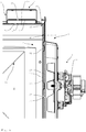
- a cooking device 1 is shown in a sectional view from the side in the region of the hot air blower device 15.
- the cooking space wall 22 has a passage opening 4 in the area of the hot air blower device 15.
- a shielding unit 7 is arranged here.
- the shielding unit 7 comprises two perforated plates 17 and 27.
- the perforated plates 17, 27 have a plurality of through openings 57. For better clarity, only one exemplary through opening 57 is shown in each perforated plate 17, 27 here.
- the perforated plates 17, 27 are arranged at a distance from one another, so that an intermediate space 37 is formed between them.
- the perforated plates 17, 27 have no through openings 57.
- the two perforated sheets 17, 27 are welded to one another outside the passage opening 4 along a joining section 47, for example by a laser welding process or a roller seam welding process.
- the perforated plates 17, 27 are connected to an upper cooking chamber wall 22 and in particular welded along a connecting section 67.
- a bead 77 is stamped here, which extends into the intermediate space 37 as far as the perforated plate 27 lying behind it. It can be provided that the perforated plates 17, 27 are connected to one another in the region of the bead and are welded, for example. As a result, a stable arrangement of the perforated plates 17.27 can be achieved even with large spaces 37.
- the hot air blower device 15 and here comprises a motor 151 which drives a rotor 153 via a shaft 152.
- the hot air blower device 15 is fastened to a housing 154, which in turn is connected to the outer perforated plate 27.
- the hot air blower device 15 has a thermal heating source, not shown here.
- the shielding unit 7 shown here has the advantage that it is arranged between the hot air blower device 15 and the cooking space 2, so that the hot air blower device 15 lies completely outside the shielding device. Since the high-frequency radiation occurring in the cooking space 2 does not even reach the hot air blower device 15 due to the shielding unit 7, the hot air blower device 15 itself no longer has to be shielded. It is particularly advantageous that this eliminates the need for complex shielding of the rotor 153 or the shaft 152. Since these are rotating parts, effective shielding is often associated with very high design costs.
- the shielding unit 7 has the two perforated plates 17, 27, which effectively prevent the high-frequency radiation from escaping from the cooking space 2.
- the perforated plates 17, 27 have a plurality of through openings 57. The heated air can easily flow into the cooking space 2 through these through openings 57. In this case, escape of the high-frequency radiation through the through openings 57 is prevented since the through openings 57 have a maximum passage width of less than one tenth of the wavelength of the high-frequency radiation in the cooking space.
- the through openings shown here are many times smaller than 1/10 of the wavelength of the high-frequency radiation to be shielded.
- a particularly good shielding is achieved by a double-layer and spaced arrangement.
- the perforated plates 17, 27 here have no through openings 57, so that particularly good shielding is also achieved in these sections.
- An advantage of the shielding unit 7 shown here is that the numerous through openings 57 together provide the through opening 4 required for connecting the hot air blower device 15 to the cooking space 2.
- the passage opening 4 and the shield can thus be provided inexpensively by one component.
- the shielding unit 7 thus has the advantage that, in addition to effective shielding, it also contributes to the structural stability of the cooking appliance 1. The use of such a shielding unit 7 can therefore save material and manufacturing effort.
- the perforated plates 17, 27 are arranged here at a distance from one another which is between four and six millimeters. Smaller or larger distances are also possible. Such a distance takes up particularly little installation space and at the same time offers sufficient scope for thermal expansion which occurs during operation.
- a particular advantage of the shielding unit 7 shown here is that it is particularly well suited for an enamel coating. Due to the through openings 57 and the correspondingly dimensioned gaps 37 as well as the joining sections 47 or connecting sections 67 formed in suitable welding processes, the entire system of cooking chamber walls 22 and shielding device 6 can be coated particularly well with an enamel coating.
- the perforated sheets 17, 27 shown here are made in particular from a steel sheet. It is also possible that the perforated plates 17, 27 are made of a stainless steel material.
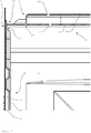
- the Figure 4 shows the cooking appliance 1 in a sectional view from the side in a region of the upper cooking chamber wall 22.
- a catalyst device 25 is arranged here in this region.
- the catalyst device 25 is used to break down odor-causing substances in a vapor which are formed during the cooking processes.
- the catalyst device 25 must be connected to the cooking chamber 2 via a corresponding passage opening 4.
- this passage opening 4 must therefore also be shielded accordingly.
- the shielding again takes place here with a shielding unit 7, which comprises two perforated plates 17, 27 arranged at a distance from one another.
- the catalyst device 25 is therefore completely outside the range in which high-frequency radiation occurs.
- the perforated plates 17, 27 have a plurality of through openings 57, only two of which are shown here by way of example.
- the passage width of the through openings 57 is here as before with reference to FIG Figure 3 described trained.
- the perforated plates 17, 27 are arranged at a distance from one another. A correspondingly effective shielding is achieved in this way.
- the shielding unit 7 is designed here in one layer only.
- the perforated plates 17, 27 are welded together along a joining section 47. No through openings 57 are provided along the joining section.
- a connection section 67 is provided here. In the connection section, that is previously in the Figure 3 Shielding unit 7 described on the rear wall connected to the shielding unit 7 of the upper wall 22 for the catalyst device 25.
- the Figure 5 shows a cooking device 1 in a perspective view from above, in which the previously in the Figure 4 shielding unit 7 described can be seen.
- the catalyst device 25 is not shown here for better clarity.
- the perforated plate 27 facing away from the cooking space and its through openings 57 can be clearly seen here.
- the outer perforated plate 27 is here placed like a lid on the perforated plate 17 facing the cooking space and connected to it along a circular joining section 47.
- the cooking device 1 is shown in a sectional view from the side. In this view, those in the Figure 3 shown hot air blower device 15 and that in the Figure 4 to recognize shown catalyst device 25 together.
- the Figure 6 shows a further sectional view of the cooking device 1 in a side view.
- a shielding unit 7 arranged on the rear side of the cooking appliance 1 with a shielding unit 7 arranged on an upper side of the cooking appliance 1 is shown.
- the upper shielding unit 7 is provided here to shield a catalyst device 25 located outside the cooking chamber 2.
- the shielding unit 7 arranged on the rear of the cooking appliance 1 serves to shield a passage opening 4 for a hot air blower device 15 arranged outside the cooking chamber 2.
Landscapes
- Physics & Mathematics (AREA)
- Electromagnetism (AREA)
- Electric Ovens (AREA)
- Baking, Grill, Roasting (AREA)
Priority Applications (1)
| Application Number | Priority Date | Filing Date | Title |
|---|---|---|---|
| PL17152624T PL3209094T3 (pl) | 2016-02-17 | 2017-01-23 | Urządzenie do gotowania |
Applications Claiming Priority (1)
| Application Number | Priority Date | Filing Date | Title |
|---|---|---|---|
| DE102016102754.5A DE102016102754A1 (de) | 2016-02-17 | 2016-02-17 | Gargerät |
Publications (2)
| Publication Number | Publication Date |
|---|---|
| EP3209094A1 EP3209094A1 (de) | 2017-08-23 |
| EP3209094B1 true EP3209094B1 (de) | 2020-04-22 |
Family
ID=57868151
Family Applications (1)
| Application Number | Title | Priority Date | Filing Date |
|---|---|---|---|
| EP17152624.7A Active EP3209094B1 (de) | 2016-02-17 | 2017-01-23 | Gargerät |
Country Status (3)
| Country | Link |
|---|---|
| EP (1) | EP3209094B1 (pl) |
| DE (1) | DE102016102754A1 (pl) |
| PL (1) | PL3209094T3 (pl) |
Families Citing this family (1)
| Publication number | Priority date | Publication date | Assignee | Title |
|---|---|---|---|---|
| US12140320B2 (en) | 2020-07-29 | 2024-11-12 | Electrolux Home Products, Inc. | Oven cavity wrapper having a structural embossment and associated convection features |
Family Cites Families (6)
| Publication number | Priority date | Publication date | Assignee | Title |
|---|---|---|---|---|
| JPS60105835A (ja) * | 1983-11-14 | 1985-06-11 | Matsushita Electric Ind Co Ltd | 加熱調理器 |
| DE29519895U1 (de) * | 1994-12-20 | 1996-02-08 | Papst-Motoren GmbH & Co KG, 78112 St Georgen | Gerät mit Bauteilen, welche im Betrieb hochfrequente Strahlung und Wärme erzeugen |
| GB2353897B (en) * | 1999-08-31 | 2002-02-20 | Lg Electronics Inc | Microwave lighting apparatus |
| JP2004278895A (ja) * | 2003-03-14 | 2004-10-07 | Matsushita Electric Ind Co Ltd | 調理器 |
| ES2590035T3 (es) * | 2009-12-30 | 2016-11-17 | Arçelik Anonim Sirketi | Un horno |
| JPWO2012073457A1 (ja) * | 2010-12-01 | 2014-05-19 | パナソニック株式会社 | 加熱調理器 |
-
2016
- 2016-02-17 DE DE102016102754.5A patent/DE102016102754A1/de not_active Ceased
-
2017
- 2017-01-23 PL PL17152624T patent/PL3209094T3/pl unknown
- 2017-01-23 EP EP17152624.7A patent/EP3209094B1/de active Active
Non-Patent Citations (1)
| Title |
|---|
| None * |
Also Published As
| Publication number | Publication date |
|---|---|
| EP3209094A1 (de) | 2017-08-23 |
| PL3209094T3 (pl) | 2020-09-21 |
| DE102016102754A1 (de) | 2017-04-27 |
Similar Documents
| Publication | Publication Date | Title |
|---|---|---|
| DE3928572C2 (pl) | ||
| DE2705395B2 (de) | Herd | |
| EP2747515A1 (de) | Gargerät | |
| EP2610557A1 (de) | Backofen mit Unterhitze und Heißluft | |
| DE69633100T2 (de) | Schutzhaube für Konvektions- und Mikrowellenofen | |
| CH656283A5 (de) | Mikrowellenofen. | |
| EP3209094B1 (de) | Gargerät | |
| DE2848658C2 (de) | Mikrowellenherd oder -ofen | |
| EP0671591A1 (de) | Vorrichtung zum Abführen von Wrasen aus einem Backofen | |
| CH661829A5 (de) | Hochfrequenzheizgeraet. | |
| DE2545531C3 (de) | Backofentür mit einem Sichtfenster | |
| DE102014224053A1 (de) | Haushaltsgargerät | |
| DE4322360A1 (de) | Einbauherd | |
| DE2615604B2 (de) | Backofen, insbesondere mit Mitteln zur pyrolytischen Reinigung mit einem Kühlluftgebläse | |
| EP4473798A1 (de) | Haushalts-mikrowellengargerät | |
| EP2444738B1 (de) | Gargerät mit einem Backofen | |
| DE102015102981B4 (de) | Frontblech für ein Gargerät, Baugruppe mit einem Frontblech und einem Innenkasten für ein Gargerät sowie Verfahren zur Herstellung der Baugruppe | |
| DE2555154C2 (de) | Umluftbackofen | |
| DE3126094C2 (de) | Elektrischer Ofen mit einer Mikrowellenheizeinrichtung und weiteren elektrischen Heizeinrichtungen, darunter eine herausnehmbare Grillheizung | |
| DE2705983A1 (de) | Mikrowellendichtung fuer kocheinrichtungen | |
| DE3742375A1 (de) | Ofen mit einem durch eine ofentuer verschliessbaren garraum zum garen von lebensmitteln | |
| EP3601888B1 (de) | Induktionsbackofenvorrichtung | |
| DE202005005143U1 (de) | Mikrowellenofen | |
| EP4380315A1 (de) | Steuerbox für ein gargerät sowie gargerät | |
| EP2463587A2 (de) | Gargerät |
Legal Events
| Date | Code | Title | Description |
|---|---|---|---|
| PUAI | Public reference made under article 153(3) epc to a published international application that has entered the european phase |
Free format text: ORIGINAL CODE: 0009012 |
|
| STAA | Information on the status of an ep patent application or granted ep patent |
Free format text: STATUS: THE APPLICATION HAS BEEN PUBLISHED |
|
| AK | Designated contracting states |
Kind code of ref document: A1 Designated state(s): AL AT BE BG CH CY CZ DE DK EE ES FI FR GB GR HR HU IE IS IT LI LT LU LV MC MK MT NL NO PL PT RO RS SE SI SK SM TR |
|
| AX | Request for extension of the european patent |
Extension state: BA ME |
|
| STAA | Information on the status of an ep patent application or granted ep patent |
Free format text: STATUS: REQUEST FOR EXAMINATION WAS MADE |
|
| 17P | Request for examination filed |
Effective date: 20180223 |
|
| RBV | Designated contracting states (corrected) |
Designated state(s): AL AT BE BG CH CY CZ DE DK EE ES FI FR GB GR HR HU IE IS IT LI LT LU LV MC MK MT NL NO PL PT RO RS SE SI SK SM TR |
|
| GRAP | Despatch of communication of intention to grant a patent |
Free format text: ORIGINAL CODE: EPIDOSNIGR1 |
|
| STAA | Information on the status of an ep patent application or granted ep patent |
Free format text: STATUS: GRANT OF PATENT IS INTENDED |
|
| INTG | Intention to grant announced |
Effective date: 20191212 |
|
| GRAS | Grant fee paid |
Free format text: ORIGINAL CODE: EPIDOSNIGR3 |
|
| GRAA | (expected) grant |
Free format text: ORIGINAL CODE: 0009210 |
|
| STAA | Information on the status of an ep patent application or granted ep patent |
Free format text: STATUS: THE PATENT HAS BEEN GRANTED |
|
| AK | Designated contracting states |
Kind code of ref document: B1 Designated state(s): AL AT BE BG CH CY CZ DE DK EE ES FI FR GB GR HR HU IE IS IT LI LT LU LV MC MK MT NL NO PL PT RO RS SE SI SK SM TR |
|
| REG | Reference to a national code |
Ref country code: CH Ref legal event code: EP |
|
| REG | Reference to a national code |
Ref country code: DE Ref legal event code: R096 Ref document number: 502017004799 Country of ref document: DE |
|
| REG | Reference to a national code |
Ref country code: IE Ref legal event code: FG4D Free format text: LANGUAGE OF EP DOCUMENT: GERMAN |
|
| REG | Reference to a national code |
Ref country code: AT Ref legal event code: REF Ref document number: 1261904 Country of ref document: AT Kind code of ref document: T Effective date: 20200515 |
|
| REG | Reference to a national code |
Ref country code: DE Ref legal event code: R084 Ref document number: 502017004799 Country of ref document: DE |
|
| REG | Reference to a national code |
Ref country code: GB Ref legal event code: 746 Effective date: 20200701 |
|
| REG | Reference to a national code |
Ref country code: LT Ref legal event code: MG4D |
|
| REG | Reference to a national code |
Ref country code: NL Ref legal event code: MP Effective date: 20200422 |
|
| PG25 | Lapsed in a contracting state [announced via postgrant information from national office to epo] |
Ref country code: GR Free format text: LAPSE BECAUSE OF FAILURE TO SUBMIT A TRANSLATION OF THE DESCRIPTION OR TO PAY THE FEE WITHIN THE PRESCRIBED TIME-LIMIT Effective date: 20200723 Ref country code: LT Free format text: LAPSE BECAUSE OF FAILURE TO SUBMIT A TRANSLATION OF THE DESCRIPTION OR TO PAY THE FEE WITHIN THE PRESCRIBED TIME-LIMIT Effective date: 20200422 Ref country code: NL Free format text: LAPSE BECAUSE OF FAILURE TO SUBMIT A TRANSLATION OF THE DESCRIPTION OR TO PAY THE FEE WITHIN THE PRESCRIBED TIME-LIMIT Effective date: 20200422 Ref country code: SE Free format text: LAPSE BECAUSE OF FAILURE TO SUBMIT A TRANSLATION OF THE DESCRIPTION OR TO PAY THE FEE WITHIN THE PRESCRIBED TIME-LIMIT Effective date: 20200422 Ref country code: PT Free format text: LAPSE BECAUSE OF FAILURE TO SUBMIT A TRANSLATION OF THE DESCRIPTION OR TO PAY THE FEE WITHIN THE PRESCRIBED TIME-LIMIT Effective date: 20200824 Ref country code: NO Free format text: LAPSE BECAUSE OF FAILURE TO SUBMIT A TRANSLATION OF THE DESCRIPTION OR TO PAY THE FEE WITHIN THE PRESCRIBED TIME-LIMIT Effective date: 20200722 Ref country code: FI Free format text: LAPSE BECAUSE OF FAILURE TO SUBMIT A TRANSLATION OF THE DESCRIPTION OR TO PAY THE FEE WITHIN THE PRESCRIBED TIME-LIMIT Effective date: 20200422 Ref country code: IS Free format text: LAPSE BECAUSE OF FAILURE TO SUBMIT A TRANSLATION OF THE DESCRIPTION OR TO PAY THE FEE WITHIN THE PRESCRIBED TIME-LIMIT Effective date: 20200822 |
|
| PG25 | Lapsed in a contracting state [announced via postgrant information from national office to epo] |
Ref country code: HR Free format text: LAPSE BECAUSE OF FAILURE TO SUBMIT A TRANSLATION OF THE DESCRIPTION OR TO PAY THE FEE WITHIN THE PRESCRIBED TIME-LIMIT Effective date: 20200422 Ref country code: LV Free format text: LAPSE BECAUSE OF FAILURE TO SUBMIT A TRANSLATION OF THE DESCRIPTION OR TO PAY THE FEE WITHIN THE PRESCRIBED TIME-LIMIT Effective date: 20200422 Ref country code: RS Free format text: LAPSE BECAUSE OF FAILURE TO SUBMIT A TRANSLATION OF THE DESCRIPTION OR TO PAY THE FEE WITHIN THE PRESCRIBED TIME-LIMIT Effective date: 20200422 Ref country code: BG Free format text: LAPSE BECAUSE OF FAILURE TO SUBMIT A TRANSLATION OF THE DESCRIPTION OR TO PAY THE FEE WITHIN THE PRESCRIBED TIME-LIMIT Effective date: 20200722 |
|
| PG25 | Lapsed in a contracting state [announced via postgrant information from national office to epo] |
Ref country code: AL Free format text: LAPSE BECAUSE OF FAILURE TO SUBMIT A TRANSLATION OF THE DESCRIPTION OR TO PAY THE FEE WITHIN THE PRESCRIBED TIME-LIMIT Effective date: 20200422 |
|
| REG | Reference to a national code |
Ref country code: DE Ref legal event code: R097 Ref document number: 502017004799 Country of ref document: DE |
|
| PG25 | Lapsed in a contracting state [announced via postgrant information from national office to epo] |
Ref country code: CZ Free format text: LAPSE BECAUSE OF FAILURE TO SUBMIT A TRANSLATION OF THE DESCRIPTION OR TO PAY THE FEE WITHIN THE PRESCRIBED TIME-LIMIT Effective date: 20200422 Ref country code: RO Free format text: LAPSE BECAUSE OF FAILURE TO SUBMIT A TRANSLATION OF THE DESCRIPTION OR TO PAY THE FEE WITHIN THE PRESCRIBED TIME-LIMIT Effective date: 20200422 Ref country code: EE Free format text: LAPSE BECAUSE OF FAILURE TO SUBMIT A TRANSLATION OF THE DESCRIPTION OR TO PAY THE FEE WITHIN THE PRESCRIBED TIME-LIMIT Effective date: 20200422 Ref country code: SM Free format text: LAPSE BECAUSE OF FAILURE TO SUBMIT A TRANSLATION OF THE DESCRIPTION OR TO PAY THE FEE WITHIN THE PRESCRIBED TIME-LIMIT Effective date: 20200422 Ref country code: ES Free format text: LAPSE BECAUSE OF FAILURE TO SUBMIT A TRANSLATION OF THE DESCRIPTION OR TO PAY THE FEE WITHIN THE PRESCRIBED TIME-LIMIT Effective date: 20200422 Ref country code: DK Free format text: LAPSE BECAUSE OF FAILURE TO SUBMIT A TRANSLATION OF THE DESCRIPTION OR TO PAY THE FEE WITHIN THE PRESCRIBED TIME-LIMIT Effective date: 20200422 |
|
| PG25 | Lapsed in a contracting state [announced via postgrant information from national office to epo] |
Ref country code: SK Free format text: LAPSE BECAUSE OF FAILURE TO SUBMIT A TRANSLATION OF THE DESCRIPTION OR TO PAY THE FEE WITHIN THE PRESCRIBED TIME-LIMIT Effective date: 20200422 |
|
| PLBE | No opposition filed within time limit |
Free format text: ORIGINAL CODE: 0009261 |
|
| STAA | Information on the status of an ep patent application or granted ep patent |
Free format text: STATUS: NO OPPOSITION FILED WITHIN TIME LIMIT |
|
| 26N | No opposition filed |
Effective date: 20210125 |
|
| PG25 | Lapsed in a contracting state [announced via postgrant information from national office to epo] |
Ref country code: SI Free format text: LAPSE BECAUSE OF FAILURE TO SUBMIT A TRANSLATION OF THE DESCRIPTION OR TO PAY THE FEE WITHIN THE PRESCRIBED TIME-LIMIT Effective date: 20200422 |
|
| PG25 | Lapsed in a contracting state [announced via postgrant information from national office to epo] |
Ref country code: MC Free format text: LAPSE BECAUSE OF FAILURE TO SUBMIT A TRANSLATION OF THE DESCRIPTION OR TO PAY THE FEE WITHIN THE PRESCRIBED TIME-LIMIT Effective date: 20200422 |
|
| REG | Reference to a national code |
Ref country code: CH Ref legal event code: PL |
|
| PG25 | Lapsed in a contracting state [announced via postgrant information from national office to epo] |
Ref country code: LU Free format text: LAPSE BECAUSE OF NON-PAYMENT OF DUE FEES Effective date: 20210123 |
|
| REG | Reference to a national code |
Ref country code: BE Ref legal event code: MM Effective date: 20210131 |
|
| PG25 | Lapsed in a contracting state [announced via postgrant information from national office to epo] |
Ref country code: LI Free format text: LAPSE BECAUSE OF NON-PAYMENT OF DUE FEES Effective date: 20210131 Ref country code: CH Free format text: LAPSE BECAUSE OF NON-PAYMENT OF DUE FEES Effective date: 20210131 |
|
| PG25 | Lapsed in a contracting state [announced via postgrant information from national office to epo] |
Ref country code: IE Free format text: LAPSE BECAUSE OF NON-PAYMENT OF DUE FEES Effective date: 20210123 |
|
| PG25 | Lapsed in a contracting state [announced via postgrant information from national office to epo] |
Ref country code: BE Free format text: LAPSE BECAUSE OF NON-PAYMENT OF DUE FEES Effective date: 20210131 |
|
| REG | Reference to a national code |
Ref country code: AT Ref legal event code: MM01 Ref document number: 1261904 Country of ref document: AT Kind code of ref document: T Effective date: 20220123 |
|
| PG25 | Lapsed in a contracting state [announced via postgrant information from national office to epo] |
Ref country code: AT Free format text: LAPSE BECAUSE OF NON-PAYMENT OF DUE FEES Effective date: 20220123 |
|
| PG25 | Lapsed in a contracting state [announced via postgrant information from national office to epo] |
Ref country code: HU Free format text: LAPSE BECAUSE OF FAILURE TO SUBMIT A TRANSLATION OF THE DESCRIPTION OR TO PAY THE FEE WITHIN THE PRESCRIBED TIME-LIMIT; INVALID AB INITIO Effective date: 20170123 |
|
| PG25 | Lapsed in a contracting state [announced via postgrant information from national office to epo] |
Ref country code: CY Free format text: LAPSE BECAUSE OF FAILURE TO SUBMIT A TRANSLATION OF THE DESCRIPTION OR TO PAY THE FEE WITHIN THE PRESCRIBED TIME-LIMIT Effective date: 20200422 |
|
| P01 | Opt-out of the competence of the unified patent court (upc) registered |
Effective date: 20230528 |
|
| PG25 | Lapsed in a contracting state [announced via postgrant information from national office to epo] |
Ref country code: MK Free format text: LAPSE BECAUSE OF FAILURE TO SUBMIT A TRANSLATION OF THE DESCRIPTION OR TO PAY THE FEE WITHIN THE PRESCRIBED TIME-LIMIT Effective date: 20200422 |
|
| PG25 | Lapsed in a contracting state [announced via postgrant information from national office to epo] |
Ref country code: MT Free format text: LAPSE BECAUSE OF FAILURE TO SUBMIT A TRANSLATION OF THE DESCRIPTION OR TO PAY THE FEE WITHIN THE PRESCRIBED TIME-LIMIT Effective date: 20200422 |
|
| PGFP | Annual fee paid to national office [announced via postgrant information from national office to epo] |
Ref country code: PL Payment date: 20251222 Year of fee payment: 10 |
|
| PGFP | Annual fee paid to national office [announced via postgrant information from national office to epo] |
Ref country code: GB Payment date: 20260126 Year of fee payment: 10 |
|
| PGFP | Annual fee paid to national office [announced via postgrant information from national office to epo] |
Ref country code: DE Payment date: 20260131 Year of fee payment: 10 |
|
| PGFP | Annual fee paid to national office [announced via postgrant information from national office to epo] |
Ref country code: IT Payment date: 20260123 Year of fee payment: 10 |
|
| PGFP | Annual fee paid to national office [announced via postgrant information from national office to epo] |
Ref country code: FR Payment date: 20260127 Year of fee payment: 10 |
|
| PGFP | Annual fee paid to national office [announced via postgrant information from national office to epo] |
Ref country code: TR Payment date: 20260113 Year of fee payment: 10 |