EP3209404B1 - Integriertes intelligentes brennstofffiltrationssystem - Google Patents
Integriertes intelligentes brennstofffiltrationssystem Download PDFInfo
- Publication number
- EP3209404B1 EP3209404B1 EP15849321.3A EP15849321A EP3209404B1 EP 3209404 B1 EP3209404 B1 EP 3209404B1 EP 15849321 A EP15849321 A EP 15849321A EP 3209404 B1 EP3209404 B1 EP 3209404B1
- Authority
- EP
- European Patent Office
- Prior art keywords
- fuel
- filter
- water separator
- water
- sensor
- Prior art date
- Legal status (The legal status is an assumption and is not a legal conclusion. Google has not performed a legal analysis and makes no representation as to the accuracy of the status listed.)
- Not-in-force
Links
Images




Classifications
-
- B—PERFORMING OPERATIONS; TRANSPORTING
- B01—PHYSICAL OR CHEMICAL PROCESSES OR APPARATUS IN GENERAL
- B01D—SEPARATION
- B01D36/00—Filter circuits or combinations of filters with other separating devices
- B01D36/003—Filters in combination with devices for the removal of liquids
- B01D36/005—Liquid level sensing means, e.g. for water in gasoil-filters
-
- B—PERFORMING OPERATIONS; TRANSPORTING
- B01—PHYSICAL OR CHEMICAL PROCESSES OR APPARATUS IN GENERAL
- B01D—SEPARATION
- B01D29/00—Filters with filtering elements stationary during filtration, e.g. pressure or suction filters, not covered by groups B01D24/00 - B01D27/00; Filtering elements therefor
- B01D29/50—Filters with filtering elements stationary during filtration, e.g. pressure or suction filters, not covered by groups B01D24/00 - B01D27/00; Filtering elements therefor with multiple filtering elements, characterised by their mutual disposition
- B01D29/56—Filters with filtering elements stationary during filtration, e.g. pressure or suction filters, not covered by groups B01D24/00 - B01D27/00; Filtering elements therefor with multiple filtering elements, characterised by their mutual disposition in series connection
-
- B—PERFORMING OPERATIONS; TRANSPORTING
- B01—PHYSICAL OR CHEMICAL PROCESSES OR APPARATUS IN GENERAL
- B01D—SEPARATION
- B01D29/00—Filters with filtering elements stationary during filtration, e.g. pressure or suction filters, not covered by groups B01D24/00 - B01D27/00; Filtering elements therefor
- B01D29/60—Filters with filtering elements stationary during filtration, e.g. pressure or suction filters, not covered by groups B01D24/00 - B01D27/00; Filtering elements therefor integrally combined with devices for controlling the filtration
- B01D29/606—Filters with filtering elements stationary during filtration, e.g. pressure or suction filters, not covered by groups B01D24/00 - B01D27/00; Filtering elements therefor integrally combined with devices for controlling the filtration by pressure measuring
-
- B—PERFORMING OPERATIONS; TRANSPORTING
- B01—PHYSICAL OR CHEMICAL PROCESSES OR APPARATUS IN GENERAL
- B01D—SEPARATION
- B01D35/00—Filtering devices having features not specifically covered by groups B01D24/00 - B01D33/00, or for applications not specifically covered by groups B01D24/00 - B01D33/00; Auxiliary devices for filtration; Filter housing constructions
- B01D35/18—Heating or cooling the filters
-
- B—PERFORMING OPERATIONS; TRANSPORTING
- B01—PHYSICAL OR CHEMICAL PROCESSES OR APPARATUS IN GENERAL
- B01D—SEPARATION
- B01D36/00—Filter circuits or combinations of filters with other separating devices
- B01D36/003—Filters in combination with devices for the removal of liquids
- B01D36/006—Purge means
-
- B—PERFORMING OPERATIONS; TRANSPORTING
- B01—PHYSICAL OR CHEMICAL PROCESSES OR APPARATUS IN GENERAL
- B01D—SEPARATION
- B01D2201/00—Details relating to filtering apparatus
- B01D2201/54—Computerised or programmable systems
-
- B—PERFORMING OPERATIONS; TRANSPORTING
- B01—PHYSICAL OR CHEMICAL PROCESSES OR APPARATUS IN GENERAL
- B01D—SEPARATION
- B01D2201/00—Details relating to filtering apparatus
- B01D2201/56—Wireless systems for monitoring the filter
Definitions
- the present application relates generally to fuel water separator filter systems.
- Embodiments of this disclosure relate generally to an integrated fuel water separator filter system. More specifically, the embodiments relate to a fuel water separator filter that includes electronic sensors to monitor the life of the fuel water separator filter.
- the fuel water separator filter system includes a fuel water separator with a first fuel water separator filter assembly and a second fuel water separator assembly.
- the first fuel water separator includes an electronic module that contains a fuel heater, a water-in-fuel sensor, and a differential pressure sensor.
- Embodiments of this disclosure relate generally to an integrated fuel water separator filter system. More specifically, the embodiments relate to a fuel water separator filter that includes electronic sensors to monitor the life of the fuel water separator filter.
- the fuel water separator filter system is configured to remove water from fuel before the fuel is supplied to an engine.
- the fuel may be diesel fuel, and the engine may be a diesel engine.
- the integrated fuel water separator filter system 100 may include a first fuel water separator filter and a second fuel water separator filter. As shown in Fig. 1 , fuel may be supplied to the first fuel water separator filter 140 from a fuel tank 110 by a fuel pump, such as a lift pump. The filtered fuel from the first fuel water separator filter 140 may then be supplied to the second fuel water separator filter 150, and the filtered fuel from the second fuel water separator filter 150 may be supplied to an engine 130.
- the first fuel water separator filter 140 may be mounted to a chassis to which the engine 130 and the fuel tank 110 are mounted.
- the chassis may be the chassis of a vehicle.
- the second fuel water separator filter 150 may be mounted to the engine 130, such as to the block of the engine 130.
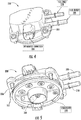
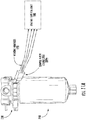
- the first fuel water separator filter 140 includes an electronic module 230, a filter head 220, and a filter 210.
- the filter head 220 may be a formed by a single casting operation, and may be formed from any suitable material, such as a polymer or metal material. According to some embodiments, the filter head 220 may be cast aluminum.
- the filter head 220 is configured to attach to the electronic module 230 and the filter 210 and provide structural support thereto.
- the filter head 220 may additionally include a mounting structure configured to mount the filter head 220 to a chassis containing an engine and a fuel tank.
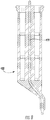
- the filter 210 may be any suitable filter element. As shown in Fig. 3 , the filter 210 may be a spin-on filter that includes a filter shell 410, filter media 440, and a drain valve 420.
- the filter media 440 may be any suitable filter media, such as a pleated filter media.
- a water reservoir 450 may be provided in the filter 210 below the filter media 440, and may be configured to collect and store water that is separated from the fuel by the fuel water separator filter.
- the filter shell 410 includes an attachment structure 412 configured to attach the filter 210 to the filter head 220.
- the attachment structure 412 may be a threaded connection, a twist-lock connection, or a bayonet connection.
- the filter shell 410 may be formed from any suitable material, such as a conductive metal material.
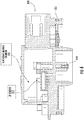
- the electronic module 230 may include an integrated electrical connector 330, a fuel inlet 310, a fuel outlet 320, and a fuel heater 340.
- the electronic module 230 is configured to be attached to the filter head 220 by an attachment mechanism, such as by screws or bolts 350.
- the electronic module 230 includes a seal 352 that is configured to seal against a surface of the filter head 220 when the electronic module is attached to the filter head.
- the seal 352 may be any appropriate structure, such as an o-ring.
- the electronic module 230 is configured to supply fuel from the fuel inlet 310 to an unfiltered fuel region of the filter 210, and receive fuel from a filtered fuel region of the filter 210 such that the filtered fuel may flow out of the fuel outlet 320.
- the fuel heater 340 is configured to heat fuel that flows through the electronic module 230 and filter 210. According to one embodiment, the fuel heater 340 may be a disk type heater. The heating of the fuel may prevent gelation of the fuel, particularly in low-temperature environments.
- the electronic module 230 may be formed from any suitable material by any appropriate process, such as from a polymer material by a casting or molding process.
- the electronic module 230 includes an electronic module chamber 370.
- the electronic module chamber 370 may include a differential pressure sensor 372.
- the differential pressure sensor 372 may be configured to measure the pressure difference between the fuel on the inlet side of the fuel water separator filter 140 and the fuel on the outlet side of the fuel water separator filter. The output of the differential pressure sensor 372 is supplied to the integrated electrical connector 330 by an electrical connection.
- the electronic module 230 may also include a contact 360 configured to electrically communicate with a water-in-fuel sensor pin 430 of the filter 210.
- the contact 360 is configured to electrically connect the integrated electrical connector 330 with the water-in-fuel sensor pin 430 when the filter 210 is installed in the filter head 220.
- the contact 360 may be a metallic contact, such as a metallic screw installed in the electronic module 230 that is configured to abut the water-in-fuel sensor pin 430.
- the water-in-fuel sensor pin 430 may be disposed within a pin support structure 432.
- the pin support structure 432 may be a center tube disposed within the filter 210.
- the pin support structure 432 may also support a strainer configured to remove any residual water from the fuel before the filtered fuel exits the fuel water separator filter, such as a hydrophobic mesh screen.
- the water-in-fuel sensor pin 430 may be configured to extend from the electronic module 230 through the center of the filter media 440 to the water reservoir 450.
- the end of the water-in-fuel sensor pin 430 may be disposed a distance from the bottom surface of water reservoir 450 associated with a water level at which water should be drained from the water reservoir, such as via the drain valve 420.
- An alternative water-in-fuel sensor may be employed in the fuel water separator that does not include a metal pin.
- a water-in-fuel sensor 530 may be employed that does not include a metal pin.
- the water-in-fuel sensor 530 may be formed from a conductive material, such that a separate conductive pin is not required.
- the water-in-fuel sensor 530 may include a strainer 534 that is configured to remove any residual water from the fuel before the filtered fuel exits the fuel water separator filter.
- the strainer 534 may be a center tube disposed within the filter 210.
- the water-in-fuel sensor 530 and strainer 534 may be formed from an electrically conductive polymer, such as a plastic material that includes conductive carbon particles.
- the water-in-fuel sensor 530 and strainer 534 may be formed together in a single forming process, and may both be formed from a hydrophobic electrically conductive polymer or plastic.
- the water-in-fuel sensor 530 may be configured to extend from the electronic module 230 through the center of the filter media 440 to the water reservoir 450.
- the end of the water-in-fuel sensor 530 may be disposed a distance from the bottom surface of water reservoir 450 associated with a water level at which water should be drained from the water reservoir, such as via the drain valve 420.
- the water-on-fuel sensor 530 may function similarly to the water-in-fuel sensor pin 430. Utilizing a water-in-fuel sensor that does not include a metal pin reduces the cost and complexity of the water-in-fuel sensor.
- control module may be an engine control unit (ECU).
- the control module may include a processor and memory, and may be connected to an electrical connector on the first fuel water separator filter.
- the electrical connector may include multiple connection pathways configured to convey sensor signals and/or electrical power, with each pathway being associated with a different sensor or heating element of the first fuel water separator filter.
- the electrical connector may include a 5 volt power supply pin.
- the fuel water separator system may be configured such that the sensors included in the first fuel water separator may monitor the filter life of the entire system, including the second fuel water separator filter.
- the first fuel water separator filter may be configured to reach an end of its useful life, by becoming clogged, before the second fuel water separator filter when the system is in operation.
- a pressure drop across the first fuel water separator such as measured by a differential pressure sensor located therein, indicates the filter life of the entire system because the first fuel water separator filter will always have more remaining life than the second fuel water separator filter.
- a life of a fuel water separator filter with no life remaining may be indicated by a pressure drop across the filter exceeding a predetermined value.
- the water-in-fuel sensor of the first fuel water separator filter is configured to determine when a water level in a water reservoir of the fuel water separator exceeds a predetermined value.
- the water-in-fuel separator includes a metal pin which is configured to connect to the electronic module when the filter is installed in the fuel water separator filter.
- the metal pin may be spring loaded such that an electrical contact is reliably established between the metal pin and a contact on the electronic module when the filter is installed in the fuel water separator.
- the metal pin is connected to a positive terminal of a power supply, such as a 5 volt power supply, and the filter shell may make contact with a ground of the control module via the filter head and chassis or with a ground of the heater element. Contact of the filter shell and the ground of the heater element may be achieved via a flexible clip provided on the heater disc. In cases where two heater discs are present in the fuel water separator filter, the flexible clip may be provided on one of the heater discs.
- a connection is made from the metal pin to the filter shell through the water, and the control module recognizes that the water level has reached a predetermined level.
- a signal such as a light, may then be provided to a user indicating that the water should be drained from the fuel water separator filter via a drain valve.
- Seals may be provided where the metal pin of the water-in-fuel sensor contacts the electronic module to prevent fuel from entering an electronic control chamber. The configuration of the water-in-fuel sensor prevents leaks from the fuel water separator filter by allowing the use of a filter shell without any external leak paths.
- the fuel heater is provided on a filter side of the electronic module.
- Two electrical contact pins of the fuel heater may be connected to the electronic module. Seals may be provided where the electrical contact pins meet the electronic module to prevent fuel from entering the electronic module chamber.
- an electronic intermediary 380 may be provided in the electronic module 230 of the fuel water separator filter.
- the electronic intermediary 380 allows the use of a single integrated electrical connector 330 to transfer signals and/or power from the sensors of the fuel water separator filter to the control module.
- the electronic intermediary 380 may be provided in the electronic module chamber 370 provided in the electronic module 230.
- the use of a single interconnected connector 330 simplifies the user interaction with the device, by providing a single electrical touch point on the fuel water separator filter. Additionally, the use of an integrated connector 330 may prevent the use of counterfeit products with the fuel water separator system that may be of low quality and result in damage to the system and/or engine.
- the electronic intermediary 380 may comprise a printed circuit board (PCB) 385.
- the PCB 385 may be connected to the heater 340, the water-in-fuel sensor 430, and the differential pressure sensor 372 by soldering connections.
- any other appropriate electrical connection between the electronic intermediary 380 and the heater 340, water-in-fuel sensor 430, and the differential pressure sensor 372 may be employed.
- the differential pressure sensor 372 may include an inlet pressure sensing element 372a positioned at the fuel inlet 310 and an outlet pressure sensing element 372b positioned at the fuel outlet 320, each of which are electrically connected to the PCB 385.
- a cap 375 may be placed over the PCB 385 and the electronic components to enclose the electronic module chamber 370.
- An attachment mechanism such as screws or bolts 373, may secure the cover 375 in place in order to hold the PCB 385 and electronic components within the electronic module chamber 370.
- the integrated electrical connector 330 is connected to the electronic intermediary 380 and may be any appropriate integrated electrical connector, such as a 4-pin or a 6-pin electrical connector.
- the integrated electrical connector 330 may be connected to the electronic intermediary 380 by any appropriate connection, such as a soldering connection or a spring connection.
- the integrated electrical connector 330 may be a 6-pin connector, and the pins may correspond to a heater voltage, a heater ground, a water-in-fuel sensor voltage, a differential pressure sensor voltage, a differential pressure sensor power, and a ground shared by the differential pressure sensor and the water-in-fuel sensor.
- the electronic module 230 may include an electronic intermediary, which may be in the form of the PCB 385 described above, that includes a controller area network (CAN) transceiver integrated circuit chip to convert the voltages from the heater, water-in-fuel sensor, and differential pressure sensor.
- CAN controller area network
- the pins may correspond to a CAN Hi voltage, a CAN Lo voltage, a power and a ground.
- Incorporating a CAN-based connection with a 4-pin connector in the electronic module may allow for existing analog circuitry on the ECU to be preserved by freeing up two analog channels in the ECU and eliminating the need for two additional wiring harnesses and connectors as compared to the 6-pin electrical connector described above.
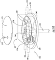
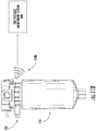
- the electronic intermediary may include a wireless transmitter 330b configured to communicate the state of the heater, water-in-fuel sensor, and differential pressure sensor.
- the wireless transmitter may be built into the housing.
- the wireless transmitter may be a radio frequency (RF) transmitter, such as an ultra-high frequency (UHF) RF transmitter or a RF transmitter configured to communicate with a RF receiver of a vehicle.
- RF radio frequency
- UHF ultra-high frequency
- the wireless transmitter may be configured to broadcast signals received from the sensors over an RF-active, UHF range.
- the wireless transmitter may be incorporated into already existing wireless monitoring systems of a vehicle.
- the wireless transmitter may be configured to communicate with a vehicle's tire pressure monitoring system 800.
- the tire pressure monitoring system 800 may be configured to accept feeds from the sensors via the wireless transmitter. This may allow for further connection to a vehicle's electronic information system in order to communicate the state of the sensors to a vehicle driver in real-time, such as through the vehicle's dashboard display.
- a two-pin electrical connector may be employed, including power and ground connections for the heater.
Landscapes
- Chemical & Material Sciences (AREA)
- Chemical Kinetics & Catalysis (AREA)
- Measuring Fluid Pressure (AREA)
Claims (13)
- Brennstoff-Wasser-Abscheiderfiltersystem (100), Folgendes umfassend:
einen ersten Brennstoff-Wasser-Abscheiderfilter (140), welcher konfiguriert ist, um an einem Fahrgestell eines Fahrzeugs montiert zu werden und um Brennstoff aus einem Brennstofftank (110) aufzunehmen, wobei der erste Brennstoff-Wasser-Abscheiderfilter (140) Folgendes einschließt:einen Filterkopf (220);einen Filter (210), welche abnehmbar mit dem Filterkopf (220) gekoppelt ist, wobei der Filter (210) Folgendes umfasst:einen Filtermantel (410),ein Filtermedium (440), welches innerhalb des Filtermantels (410) angeordnet ist, undeinen Wasser-in-Kraftstoff-Sensor (430, 530), welcher innerhalb des Filtermantels (410) angeordnet ist, undein elektronisches Modul (230), welches am Filterkopf (220) des ersten Brennstoff-Wasser-Abscheiderfilters (140) befestigt ist, wobei das elektronische Modul (230) Folgendes einschließt:eine Kammer (370) eines elektronischen Moduls, welche einen Brennstoffeinlass (310) umfasst, welcher konfiguriert ist, um Brennstoff aufzunehmen und einen Brennstoffauslass (320), welcher konfiguriert ist, um den Brennstoff nach der Filterung durch den Filter (210) auszustoßen,einen Differenzialdrucksensor (372), welcher innerhalb der Kammer (370) des elektronischen Moduls angeordnet ist,einen Brennstofferhitzer (340), wobei ein elektrischer Kontakt (360) in der Kammer des elektronischen Moduls (370) angeordnet und konfiguriert ist, um elektrisch mit dem Wasser-in-Kraftstoff-Sensor (430, 530) gekoppelt zu werden, wenn der Filter (210) mit dem Filterkopf (220) gekoppelt ist, undeinen zweiten Brennstoff-Wasser-Abscheiderfilter (150), welcher konfiguriert ist, um an einem Motor (130) montiert zu werden, wobei der erste Brennstoff-Wasser-Abscheiderfilter (140) gefilterten Brennstoff an den zweiten Brennstoff-Wasser-Abscheiderfilter (150) bereitstellt, und der zweite Brennstoff-Wasser-Abscheiderfilter (150) gefilterten Brennstoff an einen Motor (130) bereitstellt;wobei der erste Brennstoff-Wasser-Abscheiderfilter (140) im vorgelagerten Bereich des zweiten Brennstoff-Wasser-Abscheiderfilters (150) angeordnet ist. - Brennstoff-Wasser-Abscheiderfiltersystem (100) nach Anspruch 1, wobei der elektrische Kontakt (360) konfiguriert ist, um elektrisch mit einem federbelasteten Wasser-in-Kraftstoff-Sensorstift (430) des Filters (210) zu kommunizieren, wenn der Filter (210) in einem Filterkopf (220) installiert ist, wobei der Kontakt (360) ein metallischer Kontakt ist, welcher in dem elektronischen Modul (230) installiert ist, welcher konfiguriert ist, um an den Wasser-in-Kraftstoff-Sensorstift (430) anzustoßen; und welches Folgendes umfasst:
einen elektrischen Verbinder (330), welcher konfiguriert ist, um Strom und/oder Signale zwischen dem Differenzialdrucksensor (372), dem Brennstofferhitzer (340), dem Kontakt (360) und einem Steuermodul zu übertragen. - Brennstoff-Wasser-Abscheiderfiltersystem (100) nach Anspruch 2, wobei das Steuermodul eine Motorsteuerungseinheit umfasst.
- Brennstoff-Wasser-Abscheiderfiltersystem (100) nach Anspruch 2 oder 3, wobei der Brennstofferhitzer (340) ein Plattenerhitzer ist.
- Brennstoff-Wasser-Abscheiderfiltersystem (100) nach einem der Ansprüche 2 bis 4, wobei der elektrische Verbinder (330) einen Verbinder mit sechs Stiften umfasst.
- Brennstoff-Wasser-Abscheiderfiltersystem (100) nach einem der Ansprüche 2 bis 5, ferner umfassend einen Controller Area Network Transceiver, welcher konfiguriert ist, um Spannungen des Differenzialdrucksensors (372), des Brennstofferhitzers (340) und des Wasser-in-Kraftstoff-Sensors (430, 530) umzuwandeln.
- Brennstoff-Wasser-Abscheiderfiltersystem (100) nach einem der Ansprüche 2 bis 6, ferner umfassend einen drahtlosen Übertrager, welcher konfiguriert ist, um einen Zustand des Differenzialdrucksensors (372), einen Zustand des Brennstofferhitzers (340) und einen Zustand des Wasser-in-Kraftstoff-Sensors (430, 530) an das Steuermodul zu kommunizieren.
- Brennstoff-Wasser-Abscheiderfiltersystem (100) nach Anspruch 1, wobei der Filter (210) ferner Folgendes umfasst:ein Ablassventil (420);wobei der Wasser-in-Kraftstoff-Sensor (430, 530) ein Ende einschließt, welches von dem Filtermantel (410) in einem Abstand angeordnet ist, welcher mit einem vorbestimmten Volumen an Wasser verbunden ist, welches in einem Wasserspeicher (450) des Filtermantels (410) gespeichert ist.
- Brennstoff-Wasser-Abscheiderfiltersystem (100) nach Anspruch 8, wobei das Ende des Wasser-in-Kraftstoff-Sensors (430) einen Metallstift einschließt.
- Brennstoff-Wasser-Abscheiderfiltersystem (100) nach Anspruch 9, wobei der Metallstift innerhalb einer Stifthalterungsstruktur (432) angeordnet ist, wobei die Stifthalterungsstruktur (432) eine mittlere Röhre und einen Saugkorb einschließt.
- Brennstoff-Wasser-Abscheiderfiltersystem (100) nach Anspruch 8 bis 10, wobei das Ende des Wasser-in-Kraftstoff-Sensors (430, 530) in einem Abstand von einer Bodenfläche des Wasserspeichers (450) angeordnet ist.
- Brennstoff-Wasser-Abscheiderfiltersystem (100) nach einem der Ansprüche 8 bis 11, wobei der Wasser-in-Kraftstoff-Sensor (530) eine mittlere Röhre und einen Saugkorb (534) einschließt, wobei die mittlere Röhre und der Saugkorb (534) aus einem elektrisch leitfähigen Polymer gebildet sind.
- Brennstoff-Wasser-Abscheiderfiltersystem (100) nach Anspruch 12, wobei der Saugkorb (534) ein hydrophobes Maschensieb umfasst.
Applications Claiming Priority (2)
| Application Number | Priority Date | Filing Date | Title |
|---|---|---|---|
| IN5044DE2014 | 2014-10-08 | ||
| PCT/US2015/054214 WO2016057493A1 (en) | 2014-10-08 | 2015-10-06 | Integrated smart fuel filtration system |
Publications (3)
| Publication Number | Publication Date |
|---|---|
| EP3209404A1 EP3209404A1 (de) | 2017-08-30 |
| EP3209404A4 EP3209404A4 (de) | 2018-08-01 |
| EP3209404B1 true EP3209404B1 (de) | 2021-02-17 |
Family
ID=59381730
Family Applications (1)
| Application Number | Title | Priority Date | Filing Date |
|---|---|---|---|
| EP15849321.3A Not-in-force EP3209404B1 (de) | 2014-10-08 | 2015-10-06 | Integriertes intelligentes brennstofffiltrationssystem |
Country Status (1)
| Country | Link |
|---|---|
| EP (1) | EP3209404B1 (de) |
Family Cites Families (5)
| Publication number | Priority date | Publication date | Assignee | Title |
|---|---|---|---|---|
| US20040118764A1 (en) * | 2002-12-20 | 2004-06-24 | Miller Terry L. | Multiple fuel filter pump module |
| WO2005059862A1 (ja) * | 2003-12-15 | 2005-06-30 | Hitachi, Ltd. | 車載制御装置の情報更新方法と更新情報通信システム、および、車両搭載制御装置と情報管理基地局装置 |
| US9453754B2 (en) * | 2010-04-27 | 2016-09-27 | Cummins Filtration Ip, Inc. | Multi-conductor water in fuel sensor for fill rate detection |
| DE102012005206A1 (de) * | 2012-03-16 | 2013-09-19 | Mann + Hummel Gmbh | Kraftstofffilter einer Brennkraftmaschine und Heiz-Sensor-Modul eines Kraftstofffilters |
| US9112295B2 (en) * | 2012-07-13 | 2015-08-18 | Robert Bosch Gmbh | Modular electrical connector and connection method |
-
2015
- 2015-10-06 EP EP15849321.3A patent/EP3209404B1/de not_active Not-in-force
Non-Patent Citations (1)
| Title |
|---|
| None * |
Also Published As
| Publication number | Publication date |
|---|---|
| EP3209404A1 (de) | 2017-08-30 |
| EP3209404A4 (de) | 2018-08-01 |
Similar Documents
| Publication | Publication Date | Title |
|---|---|---|
| US20170298881A1 (en) | Integrated smart fuel filtration system | |
| US10821382B2 (en) | Electronic filter detection feature for liquid filtration systems | |
| US10010815B2 (en) | Fuel filter of an internal combustion engine and heating sensor module of a fuel filter | |
| RU2605129C2 (ru) | Фильтр для текучей среды с элементом стыковки картриджа фильтра и корпуса | |
| CN100497926C (zh) | 共轨型高压直接喷射柴油机所使用的燃油过滤器 | |
| CN108744689B (zh) | 提供过滤器识别的装置、系统和方法 | |
| EP0362114A2 (de) | Kraftstoffilter und Wasserabscheider, montiert auf beiden Seiten eines Gehäuses | |
| CN1972734A (zh) | 用于柴油内燃机的燃料过滤器 | |
| CN102022235B (zh) | 具有加热装置和水传感器的过滤装置 | |
| EP3667262B1 (de) | Fluidsensoranordnung | |
| WO2020167453A1 (en) | Sensing assembly for use in wirelessly monitoring a status of a filter element | |
| EP3033518B1 (de) | Kraftstofffiltervorrichtung | |
| EP3209404B1 (de) | Integriertes intelligentes brennstofffiltrationssystem | |
| CN210833766U (zh) | 集成式液位传感器 | |
| KR101775119B1 (ko) | 디젤차량의 모듈화된 연료필터장치 | |
| EP1914417A2 (de) | Filter für Brennkraftmaschinen | |
| CN107975405A (zh) | 尿素泵模块 | |
| JP2015225047A (ja) | 液体センサ | |
| CN207036333U (zh) | 一种新型采集分析仪 | |
| JP2015145625A (ja) | センサ装置 | |
| CN119246665A (zh) | 一种过滤检测环及油路 | |
| SE540260C2 (en) | Fuel system and method for indicating water in fuel by use of a conductivity sensor |
Legal Events
| Date | Code | Title | Description |
|---|---|---|---|
| STAA | Information on the status of an ep patent application or granted ep patent |
Free format text: STATUS: THE INTERNATIONAL PUBLICATION HAS BEEN MADE |
|
| PUAI | Public reference made under article 153(3) epc to a published international application that has entered the european phase |
Free format text: ORIGINAL CODE: 0009012 |
|
| STAA | Information on the status of an ep patent application or granted ep patent |
Free format text: STATUS: REQUEST FOR EXAMINATION WAS MADE |
|
| 17P | Request for examination filed |
Effective date: 20170406 |
|
| AK | Designated contracting states |
Kind code of ref document: A1 Designated state(s): AL AT BE BG CH CY CZ DE DK EE ES FI FR GB GR HR HU IE IS IT LI LT LU LV MC MK MT NL NO PL PT RO RS SE SI SK SM TR |
|
| AX | Request for extension of the european patent |
Extension state: BA ME |
|
| RIN1 | Information on inventor provided before grant (corrected) |
Inventor name: SEKAR, MANO Inventor name: MALGORN, GERARD Inventor name: VAIDYA, ABHIJEET Inventor name: ROBINSON, CASEY Inventor name: YESANE, SWATI S. Inventor name: JIANG, ZEMIN Inventor name: SEDZIOL, JON Inventor name: SHIMPI, ABHIJIT |
|
| DAV | Request for validation of the european patent (deleted) | ||
| DAX | Request for extension of the european patent (deleted) | ||
| RIN1 | Information on inventor provided before grant (corrected) |
Inventor name: JIANG, ZEMIN Inventor name: SEDZIOL, JON Inventor name: SEKAR, MANO Inventor name: YESANE, SWATI S. Inventor name: ROBINSON, CASEY Inventor name: VAIDYA, ABHIJEET Inventor name: SHIMPI, ABHIJIT Inventor name: MALGORN, GERARD |
|
| A4 | Supplementary search report drawn up and despatched |
Effective date: 20180702 |
|
| RIC1 | Information provided on ipc code assigned before grant |
Ipc: B01D 29/56 20060101ALI20180626BHEP Ipc: B01D 35/18 20060101ALI20180626BHEP Ipc: B01D 29/60 20060101ALI20180626BHEP Ipc: B01D 17/02 20060101AFI20180626BHEP Ipc: B01D 36/00 20060101ALI20180626BHEP |
|
| STAA | Information on the status of an ep patent application or granted ep patent |
Free format text: STATUS: EXAMINATION IS IN PROGRESS |
|
| 17Q | First examination report despatched |
Effective date: 20191220 |
|
| GRAP | Despatch of communication of intention to grant a patent |
Free format text: ORIGINAL CODE: EPIDOSNIGR1 |
|
| STAA | Information on the status of an ep patent application or granted ep patent |
Free format text: STATUS: GRANT OF PATENT IS INTENDED |
|
| INTG | Intention to grant announced |
Effective date: 20200914 |
|
| GRAS | Grant fee paid |
Free format text: ORIGINAL CODE: EPIDOSNIGR3 |
|
| GRAA | (expected) grant |
Free format text: ORIGINAL CODE: 0009210 |
|
| STAA | Information on the status of an ep patent application or granted ep patent |
Free format text: STATUS: THE PATENT HAS BEEN GRANTED |
|
| AK | Designated contracting states |
Kind code of ref document: B1 Designated state(s): AL AT BE BG CH CY CZ DE DK EE ES FI FR GB GR HR HU IE IS IT LI LT LU LV MC MK MT NL NO PL PT RO RS SE SI SK SM TR |
|
| REG | Reference to a national code |
Ref country code: GB Ref legal event code: FG4D |
|
| REG | Reference to a national code |
Ref country code: CH Ref legal event code: EP |
|
| REG | Reference to a national code |
Ref country code: DE Ref legal event code: R096 Ref document number: 602015065783 Country of ref document: DE |
|
| REG | Reference to a national code |
Ref country code: AT Ref legal event code: REF Ref document number: 1360716 Country of ref document: AT Kind code of ref document: T Effective date: 20210315 |
|
| REG | Reference to a national code |
Ref country code: IE Ref legal event code: FG4D |
|
| REG | Reference to a national code |
Ref country code: LT Ref legal event code: MG9D |
|
| REG | Reference to a national code |
Ref country code: NL Ref legal event code: MP Effective date: 20210217 |
|
| PG25 | Lapsed in a contracting state [announced via postgrant information from national office to epo] |
Ref country code: BG Free format text: LAPSE BECAUSE OF FAILURE TO SUBMIT A TRANSLATION OF THE DESCRIPTION OR TO PAY THE FEE WITHIN THE PRESCRIBED TIME-LIMIT Effective date: 20210517 Ref country code: HR Free format text: LAPSE BECAUSE OF FAILURE TO SUBMIT A TRANSLATION OF THE DESCRIPTION OR TO PAY THE FEE WITHIN THE PRESCRIBED TIME-LIMIT Effective date: 20210217 Ref country code: GR Free format text: LAPSE BECAUSE OF FAILURE TO SUBMIT A TRANSLATION OF THE DESCRIPTION OR TO PAY THE FEE WITHIN THE PRESCRIBED TIME-LIMIT Effective date: 20210518 Ref country code: FI Free format text: LAPSE BECAUSE OF FAILURE TO SUBMIT A TRANSLATION OF THE DESCRIPTION OR TO PAY THE FEE WITHIN THE PRESCRIBED TIME-LIMIT Effective date: 20210217 Ref country code: NO Free format text: LAPSE BECAUSE OF FAILURE TO SUBMIT A TRANSLATION OF THE DESCRIPTION OR TO PAY THE FEE WITHIN THE PRESCRIBED TIME-LIMIT Effective date: 20210517 Ref country code: PT Free format text: LAPSE BECAUSE OF FAILURE TO SUBMIT A TRANSLATION OF THE DESCRIPTION OR TO PAY THE FEE WITHIN THE PRESCRIBED TIME-LIMIT Effective date: 20210617 Ref country code: LT Free format text: LAPSE BECAUSE OF FAILURE TO SUBMIT A TRANSLATION OF THE DESCRIPTION OR TO PAY THE FEE WITHIN THE PRESCRIBED TIME-LIMIT Effective date: 20210217 |
|
| REG | Reference to a national code |
Ref country code: AT Ref legal event code: MK05 Ref document number: 1360716 Country of ref document: AT Kind code of ref document: T Effective date: 20210217 |
|
| PG25 | Lapsed in a contracting state [announced via postgrant information from national office to epo] |
Ref country code: SE Free format text: LAPSE BECAUSE OF FAILURE TO SUBMIT A TRANSLATION OF THE DESCRIPTION OR TO PAY THE FEE WITHIN THE PRESCRIBED TIME-LIMIT Effective date: 20210217 Ref country code: LV Free format text: LAPSE BECAUSE OF FAILURE TO SUBMIT A TRANSLATION OF THE DESCRIPTION OR TO PAY THE FEE WITHIN THE PRESCRIBED TIME-LIMIT Effective date: 20210217 Ref country code: PL Free format text: LAPSE BECAUSE OF FAILURE TO SUBMIT A TRANSLATION OF THE DESCRIPTION OR TO PAY THE FEE WITHIN THE PRESCRIBED TIME-LIMIT Effective date: 20210217 Ref country code: RS Free format text: LAPSE BECAUSE OF FAILURE TO SUBMIT A TRANSLATION OF THE DESCRIPTION OR TO PAY THE FEE WITHIN THE PRESCRIBED TIME-LIMIT Effective date: 20210217 Ref country code: NL Free format text: LAPSE BECAUSE OF FAILURE TO SUBMIT A TRANSLATION OF THE DESCRIPTION OR TO PAY THE FEE WITHIN THE PRESCRIBED TIME-LIMIT Effective date: 20210217 |
|
| PG25 | Lapsed in a contracting state [announced via postgrant information from national office to epo] |
Ref country code: IS Free format text: LAPSE BECAUSE OF FAILURE TO SUBMIT A TRANSLATION OF THE DESCRIPTION OR TO PAY THE FEE WITHIN THE PRESCRIBED TIME-LIMIT Effective date: 20210617 |
|
| PG25 | Lapsed in a contracting state [announced via postgrant information from national office to epo] |
Ref country code: SM Free format text: LAPSE BECAUSE OF FAILURE TO SUBMIT A TRANSLATION OF THE DESCRIPTION OR TO PAY THE FEE WITHIN THE PRESCRIBED TIME-LIMIT Effective date: 20210217 Ref country code: AT Free format text: LAPSE BECAUSE OF FAILURE TO SUBMIT A TRANSLATION OF THE DESCRIPTION OR TO PAY THE FEE WITHIN THE PRESCRIBED TIME-LIMIT Effective date: 20210217 Ref country code: EE Free format text: LAPSE BECAUSE OF FAILURE TO SUBMIT A TRANSLATION OF THE DESCRIPTION OR TO PAY THE FEE WITHIN THE PRESCRIBED TIME-LIMIT Effective date: 20210217 Ref country code: CZ Free format text: LAPSE BECAUSE OF FAILURE TO SUBMIT A TRANSLATION OF THE DESCRIPTION OR TO PAY THE FEE WITHIN THE PRESCRIBED TIME-LIMIT Effective date: 20210217 |
|
| REG | Reference to a national code |
Ref country code: DE Ref legal event code: R097 Ref document number: 602015065783 Country of ref document: DE |
|
| PG25 | Lapsed in a contracting state [announced via postgrant information from national office to epo] |
Ref country code: DK Free format text: LAPSE BECAUSE OF FAILURE TO SUBMIT A TRANSLATION OF THE DESCRIPTION OR TO PAY THE FEE WITHIN THE PRESCRIBED TIME-LIMIT Effective date: 20210217 Ref country code: SK Free format text: LAPSE BECAUSE OF FAILURE TO SUBMIT A TRANSLATION OF THE DESCRIPTION OR TO PAY THE FEE WITHIN THE PRESCRIBED TIME-LIMIT Effective date: 20210217 Ref country code: RO Free format text: LAPSE BECAUSE OF FAILURE TO SUBMIT A TRANSLATION OF THE DESCRIPTION OR TO PAY THE FEE WITHIN THE PRESCRIBED TIME-LIMIT Effective date: 20210217 |
|
| PLBE | No opposition filed within time limit |
Free format text: ORIGINAL CODE: 0009261 |
|
| STAA | Information on the status of an ep patent application or granted ep patent |
Free format text: STATUS: NO OPPOSITION FILED WITHIN TIME LIMIT |
|
| 26N | No opposition filed |
Effective date: 20211118 |
|
| PG25 | Lapsed in a contracting state [announced via postgrant information from national office to epo] |
Ref country code: AL Free format text: LAPSE BECAUSE OF FAILURE TO SUBMIT A TRANSLATION OF THE DESCRIPTION OR TO PAY THE FEE WITHIN THE PRESCRIBED TIME-LIMIT Effective date: 20210217 Ref country code: ES Free format text: LAPSE BECAUSE OF FAILURE TO SUBMIT A TRANSLATION OF THE DESCRIPTION OR TO PAY THE FEE WITHIN THE PRESCRIBED TIME-LIMIT Effective date: 20210217 |
|
| PGFP | Annual fee paid to national office [announced via postgrant information from national office to epo] |
Ref country code: GB Payment date: 20211027 Year of fee payment: 7 Ref country code: DE Payment date: 20211027 Year of fee payment: 7 |
|
| PG25 | Lapsed in a contracting state [announced via postgrant information from national office to epo] |
Ref country code: SI Free format text: LAPSE BECAUSE OF FAILURE TO SUBMIT A TRANSLATION OF THE DESCRIPTION OR TO PAY THE FEE WITHIN THE PRESCRIBED TIME-LIMIT Effective date: 20210217 |
|
| PGFP | Annual fee paid to national office [announced via postgrant information from national office to epo] |
Ref country code: FR Payment date: 20211025 Year of fee payment: 7 |
|
| PG25 | Lapsed in a contracting state [announced via postgrant information from national office to epo] |
Ref country code: IT Free format text: LAPSE BECAUSE OF FAILURE TO SUBMIT A TRANSLATION OF THE DESCRIPTION OR TO PAY THE FEE WITHIN THE PRESCRIBED TIME-LIMIT Effective date: 20210217 |
|
| PG25 | Lapsed in a contracting state [announced via postgrant information from national office to epo] |
Ref country code: IS Free format text: LAPSE BECAUSE OF FAILURE TO SUBMIT A TRANSLATION OF THE DESCRIPTION OR TO PAY THE FEE WITHIN THE PRESCRIBED TIME-LIMIT Effective date: 20210617 |
|
| REG | Reference to a national code |
Ref country code: CH Ref legal event code: PL |
|
| REG | Reference to a national code |
Ref country code: BE Ref legal event code: MM Effective date: 20211031 |
|
| PG25 | Lapsed in a contracting state [announced via postgrant information from national office to epo] |
Ref country code: MC Free format text: LAPSE BECAUSE OF FAILURE TO SUBMIT A TRANSLATION OF THE DESCRIPTION OR TO PAY THE FEE WITHIN THE PRESCRIBED TIME-LIMIT Effective date: 20210217 |
|
| PG25 | Lapsed in a contracting state [announced via postgrant information from national office to epo] |
Ref country code: LU Free format text: LAPSE BECAUSE OF NON-PAYMENT OF DUE FEES Effective date: 20211006 Ref country code: BE Free format text: LAPSE BECAUSE OF NON-PAYMENT OF DUE FEES Effective date: 20211031 |
|
| PG25 | Lapsed in a contracting state [announced via postgrant information from national office to epo] |
Ref country code: LI Free format text: LAPSE BECAUSE OF NON-PAYMENT OF DUE FEES Effective date: 20211031 Ref country code: CH Free format text: LAPSE BECAUSE OF NON-PAYMENT OF DUE FEES Effective date: 20211031 |
|
| PG25 | Lapsed in a contracting state [announced via postgrant information from national office to epo] |
Ref country code: IE Free format text: LAPSE BECAUSE OF NON-PAYMENT OF DUE FEES Effective date: 20211006 |
|
| REG | Reference to a national code |
Ref country code: DE Ref legal event code: R119 Ref document number: 602015065783 Country of ref document: DE |
|
| PG25 | Lapsed in a contracting state [announced via postgrant information from national office to epo] |
Ref country code: HU Free format text: LAPSE BECAUSE OF FAILURE TO SUBMIT A TRANSLATION OF THE DESCRIPTION OR TO PAY THE FEE WITHIN THE PRESCRIBED TIME-LIMIT; INVALID AB INITIO Effective date: 20151006 |
|
| P01 | Opt-out of the competence of the unified patent court (upc) registered |
Effective date: 20230510 |
|
| GBPC | Gb: european patent ceased through non-payment of renewal fee |
Effective date: 20221006 |
|
| PG25 | Lapsed in a contracting state [announced via postgrant information from national office to epo] |
Ref country code: CY Free format text: LAPSE BECAUSE OF FAILURE TO SUBMIT A TRANSLATION OF THE DESCRIPTION OR TO PAY THE FEE WITHIN THE PRESCRIBED TIME-LIMIT Effective date: 20210217 |
|
| PG25 | Lapsed in a contracting state [announced via postgrant information from national office to epo] |
Ref country code: FR Free format text: LAPSE BECAUSE OF NON-PAYMENT OF DUE FEES Effective date: 20221031 Ref country code: DE Free format text: LAPSE BECAUSE OF NON-PAYMENT OF DUE FEES Effective date: 20230503 |
|
| PG25 | Lapsed in a contracting state [announced via postgrant information from national office to epo] |
Ref country code: GB Free format text: LAPSE BECAUSE OF NON-PAYMENT OF DUE FEES Effective date: 20221006 |
|
| PG25 | Lapsed in a contracting state [announced via postgrant information from national office to epo] |
Ref country code: MK Free format text: LAPSE BECAUSE OF FAILURE TO SUBMIT A TRANSLATION OF THE DESCRIPTION OR TO PAY THE FEE WITHIN THE PRESCRIBED TIME-LIMIT Effective date: 20210217 |
|
| PG25 | Lapsed in a contracting state [announced via postgrant information from national office to epo] |
Ref country code: MT Free format text: LAPSE BECAUSE OF FAILURE TO SUBMIT A TRANSLATION OF THE DESCRIPTION OR TO PAY THE FEE WITHIN THE PRESCRIBED TIME-LIMIT Effective date: 20210217 |
|
| PG25 | Lapsed in a contracting state [announced via postgrant information from national office to epo] |
Ref country code: TR Free format text: LAPSE BECAUSE OF FAILURE TO SUBMIT A TRANSLATION OF THE DESCRIPTION OR TO PAY THE FEE WITHIN THE PRESCRIBED TIME-LIMIT Effective date: 20210217 |