EP3209809B1 - Temperierte gaszuleitung mit an mehreren stellen eingespeisten verdünnungsgasströmen - Google Patents
Temperierte gaszuleitung mit an mehreren stellen eingespeisten verdünnungsgasströmen Download PDFInfo
- Publication number
- EP3209809B1 EP3209809B1 EP15781046.6A EP15781046A EP3209809B1 EP 3209809 B1 EP3209809 B1 EP 3209809B1 EP 15781046 A EP15781046 A EP 15781046A EP 3209809 B1 EP3209809 B1 EP 3209809B1
- Authority
- EP
- European Patent Office
- Prior art keywords
- temperature
- gas
- line
- dilution
- controlling
- Prior art date
- Legal status (The legal status is an assumption and is not a legal conclusion. Google has not performed a legal analysis and makes no representation as to the accuracy of the status listed.)
- Active
Links
- 238000010790 dilution Methods 0.000 title claims description 24
- 239000012895 dilution Substances 0.000 title claims description 24
- 239000007789 gas Substances 0.000 claims description 206
- 239000007858 starting material Substances 0.000 claims description 77
- 238000000034 method Methods 0.000 claims description 48
- 239000012159 carrier gas Substances 0.000 claims description 33
- 238000011144 upstream manufacturing Methods 0.000 claims description 30
- 239000000758 substrate Substances 0.000 claims description 21
- 239000007788 liquid Substances 0.000 claims description 13
- 239000007787 solid Substances 0.000 claims description 13
- 239000010410 layer Substances 0.000 claims description 11
- 238000009833 condensation Methods 0.000 claims description 10
- 230000005494 condensation Effects 0.000 claims description 10
- 238000000151 deposition Methods 0.000 claims description 7
- 230000008021 deposition Effects 0.000 claims description 3
- 239000012044 organic layer Substances 0.000 claims description 3
- 230000032258 transport Effects 0.000 description 51
- 239000003085 diluting agent Substances 0.000 description 35
- 238000002156 mixing Methods 0.000 description 22
- 238000005496 tempering Methods 0.000 description 21
- 238000010438 heat treatment Methods 0.000 description 18
- 238000001816 cooling Methods 0.000 description 10
- 239000002184 metal Substances 0.000 description 6
- 229910052751 metal Inorganic materials 0.000 description 6
- XKRFYHLGVUSROY-UHFFFAOYSA-N Argon Chemical compound [Ar] XKRFYHLGVUSROY-UHFFFAOYSA-N 0.000 description 4
- IJGRMHOSHXDMSA-UHFFFAOYSA-N Atomic nitrogen Chemical compound N#N IJGRMHOSHXDMSA-UHFFFAOYSA-N 0.000 description 4
- 239000000203 mixture Substances 0.000 description 4
- 125000002915 carbonyl group Chemical group [*:2]C([*:1])=O 0.000 description 3
- 238000000576 coating method Methods 0.000 description 3
- 239000011261 inert gas Substances 0.000 description 3
- 230000008016 vaporization Effects 0.000 description 3
- UFHFLCQGNIYNRP-UHFFFAOYSA-N Hydrogen Chemical compound [H][H] UFHFLCQGNIYNRP-UHFFFAOYSA-N 0.000 description 2
- 229910052786 argon Inorganic materials 0.000 description 2
- 239000011248 coating agent Substances 0.000 description 2
- 239000001257 hydrogen Substances 0.000 description 2
- 229910052739 hydrogen Inorganic materials 0.000 description 2
- 229910052757 nitrogen Inorganic materials 0.000 description 2
- 239000011368 organic material Substances 0.000 description 2
- 230000001105 regulatory effect Effects 0.000 description 2
- 230000007423 decrease Effects 0.000 description 1
- 238000009795 derivation Methods 0.000 description 1
- 238000001704 evaporation Methods 0.000 description 1
- 230000008020 evaporation Effects 0.000 description 1
- 150000002739 metals Chemical class 0.000 description 1
- 239000000843 powder Substances 0.000 description 1
- 238000004886 process control Methods 0.000 description 1
- 230000005855 radiation Effects 0.000 description 1
- 230000000284 resting effect Effects 0.000 description 1
- 239000000243 solution Substances 0.000 description 1
- 238000005979 thermal decomposition reaction Methods 0.000 description 1
- 238000009834 vaporization Methods 0.000 description 1
Images

Classifications
-
- C—CHEMISTRY; METALLURGY
- C23—COATING METALLIC MATERIAL; COATING MATERIAL WITH METALLIC MATERIAL; CHEMICAL SURFACE TREATMENT; DIFFUSION TREATMENT OF METALLIC MATERIAL; COATING BY VACUUM EVAPORATION, BY SPUTTERING, BY ION IMPLANTATION OR BY CHEMICAL VAPOUR DEPOSITION, IN GENERAL; INHIBITING CORROSION OF METALLIC MATERIAL OR INCRUSTATION IN GENERAL
- C23C—COATING METALLIC MATERIAL; COATING MATERIAL WITH METALLIC MATERIAL; SURFACE TREATMENT OF METALLIC MATERIAL BY DIFFUSION INTO THE SURFACE, BY CHEMICAL CONVERSION OR SUBSTITUTION; COATING BY VACUUM EVAPORATION, BY SPUTTERING, BY ION IMPLANTATION OR BY CHEMICAL VAPOUR DEPOSITION, IN GENERAL
- C23C14/00—Coating by vacuum evaporation, by sputtering or by ion implantation of the coating forming material
- C23C14/06—Coating by vacuum evaporation, by sputtering or by ion implantation of the coating forming material characterised by the coating material
- C23C14/12—Organic material
-
- C—CHEMISTRY; METALLURGY
- C23—COATING METALLIC MATERIAL; COATING MATERIAL WITH METALLIC MATERIAL; CHEMICAL SURFACE TREATMENT; DIFFUSION TREATMENT OF METALLIC MATERIAL; COATING BY VACUUM EVAPORATION, BY SPUTTERING, BY ION IMPLANTATION OR BY CHEMICAL VAPOUR DEPOSITION, IN GENERAL; INHIBITING CORROSION OF METALLIC MATERIAL OR INCRUSTATION IN GENERAL
- C23C—COATING METALLIC MATERIAL; COATING MATERIAL WITH METALLIC MATERIAL; SURFACE TREATMENT OF METALLIC MATERIAL BY DIFFUSION INTO THE SURFACE, BY CHEMICAL CONVERSION OR SUBSTITUTION; COATING BY VACUUM EVAPORATION, BY SPUTTERING, BY ION IMPLANTATION OR BY CHEMICAL VAPOUR DEPOSITION, IN GENERAL
- C23C14/00—Coating by vacuum evaporation, by sputtering or by ion implantation of the coating forming material
- C23C14/22—Coating by vacuum evaporation, by sputtering or by ion implantation of the coating forming material characterised by the process of coating
- C23C14/228—Gas flow assisted PVD deposition
-
- C—CHEMISTRY; METALLURGY
- C23—COATING METALLIC MATERIAL; COATING MATERIAL WITH METALLIC MATERIAL; CHEMICAL SURFACE TREATMENT; DIFFUSION TREATMENT OF METALLIC MATERIAL; COATING BY VACUUM EVAPORATION, BY SPUTTERING, BY ION IMPLANTATION OR BY CHEMICAL VAPOUR DEPOSITION, IN GENERAL; INHIBITING CORROSION OF METALLIC MATERIAL OR INCRUSTATION IN GENERAL
- C23C—COATING METALLIC MATERIAL; COATING MATERIAL WITH METALLIC MATERIAL; SURFACE TREATMENT OF METALLIC MATERIAL BY DIFFUSION INTO THE SURFACE, BY CHEMICAL CONVERSION OR SUBSTITUTION; COATING BY VACUUM EVAPORATION, BY SPUTTERING, BY ION IMPLANTATION OR BY CHEMICAL VAPOUR DEPOSITION, IN GENERAL
- C23C14/00—Coating by vacuum evaporation, by sputtering or by ion implantation of the coating forming material
- C23C14/22—Coating by vacuum evaporation, by sputtering or by ion implantation of the coating forming material characterised by the process of coating
- C23C14/24—Vacuum evaporation
- C23C14/243—Crucibles for source material
-
- C—CHEMISTRY; METALLURGY
- C23—COATING METALLIC MATERIAL; COATING MATERIAL WITH METALLIC MATERIAL; CHEMICAL SURFACE TREATMENT; DIFFUSION TREATMENT OF METALLIC MATERIAL; COATING BY VACUUM EVAPORATION, BY SPUTTERING, BY ION IMPLANTATION OR BY CHEMICAL VAPOUR DEPOSITION, IN GENERAL; INHIBITING CORROSION OF METALLIC MATERIAL OR INCRUSTATION IN GENERAL
- C23C—COATING METALLIC MATERIAL; COATING MATERIAL WITH METALLIC MATERIAL; SURFACE TREATMENT OF METALLIC MATERIAL BY DIFFUSION INTO THE SURFACE, BY CHEMICAL CONVERSION OR SUBSTITUTION; COATING BY VACUUM EVAPORATION, BY SPUTTERING, BY ION IMPLANTATION OR BY CHEMICAL VAPOUR DEPOSITION, IN GENERAL
- C23C14/00—Coating by vacuum evaporation, by sputtering or by ion implantation of the coating forming material
- C23C14/22—Coating by vacuum evaporation, by sputtering or by ion implantation of the coating forming material characterised by the process of coating
- C23C14/54—Controlling or regulating the coating process
- C23C14/541—Heating or cooling of the substrates
-
- C—CHEMISTRY; METALLURGY
- C23—COATING METALLIC MATERIAL; COATING MATERIAL WITH METALLIC MATERIAL; CHEMICAL SURFACE TREATMENT; DIFFUSION TREATMENT OF METALLIC MATERIAL; COATING BY VACUUM EVAPORATION, BY SPUTTERING, BY ION IMPLANTATION OR BY CHEMICAL VAPOUR DEPOSITION, IN GENERAL; INHIBITING CORROSION OF METALLIC MATERIAL OR INCRUSTATION IN GENERAL
- C23C—COATING METALLIC MATERIAL; COATING MATERIAL WITH METALLIC MATERIAL; SURFACE TREATMENT OF METALLIC MATERIAL BY DIFFUSION INTO THE SURFACE, BY CHEMICAL CONVERSION OR SUBSTITUTION; COATING BY VACUUM EVAPORATION, BY SPUTTERING, BY ION IMPLANTATION OR BY CHEMICAL VAPOUR DEPOSITION, IN GENERAL
- C23C16/00—Chemical coating by decomposition of gaseous compounds, without leaving reaction products of surface material in the coating, i.e. chemical vapour deposition [CVD] processes
- C23C16/44—Chemical coating by decomposition of gaseous compounds, without leaving reaction products of surface material in the coating, i.e. chemical vapour deposition [CVD] processes characterised by the method of coating
- C23C16/448—Chemical coating by decomposition of gaseous compounds, without leaving reaction products of surface material in the coating, i.e. chemical vapour deposition [CVD] processes characterised by the method of coating characterised by the method used for generating reactive gas streams, e.g. by evaporation or sublimation of precursor materials
- C23C16/4481—Chemical coating by decomposition of gaseous compounds, without leaving reaction products of surface material in the coating, i.e. chemical vapour deposition [CVD] processes characterised by the method of coating characterised by the method used for generating reactive gas streams, e.g. by evaporation or sublimation of precursor materials by evaporation using carrier gas in contact with the source material
-
- C—CHEMISTRY; METALLURGY
- C23—COATING METALLIC MATERIAL; COATING MATERIAL WITH METALLIC MATERIAL; CHEMICAL SURFACE TREATMENT; DIFFUSION TREATMENT OF METALLIC MATERIAL; COATING BY VACUUM EVAPORATION, BY SPUTTERING, BY ION IMPLANTATION OR BY CHEMICAL VAPOUR DEPOSITION, IN GENERAL; INHIBITING CORROSION OF METALLIC MATERIAL OR INCRUSTATION IN GENERAL
- C23C—COATING METALLIC MATERIAL; COATING MATERIAL WITH METALLIC MATERIAL; SURFACE TREATMENT OF METALLIC MATERIAL BY DIFFUSION INTO THE SURFACE, BY CHEMICAL CONVERSION OR SUBSTITUTION; COATING BY VACUUM EVAPORATION, BY SPUTTERING, BY ION IMPLANTATION OR BY CHEMICAL VAPOUR DEPOSITION, IN GENERAL
- C23C16/00—Chemical coating by decomposition of gaseous compounds, without leaving reaction products of surface material in the coating, i.e. chemical vapour deposition [CVD] processes
- C23C16/44—Chemical coating by decomposition of gaseous compounds, without leaving reaction products of surface material in the coating, i.e. chemical vapour deposition [CVD] processes characterised by the method of coating
- C23C16/455—Chemical coating by decomposition of gaseous compounds, without leaving reaction products of surface material in the coating, i.e. chemical vapour deposition [CVD] processes characterised by the method of coating characterised by the method used for introducing gases into reaction chamber or for modifying gas flows in reaction chamber
- C23C16/45561—Gas plumbing upstream of the reaction chamber
-
- C—CHEMISTRY; METALLURGY
- C23—COATING METALLIC MATERIAL; COATING MATERIAL WITH METALLIC MATERIAL; CHEMICAL SURFACE TREATMENT; DIFFUSION TREATMENT OF METALLIC MATERIAL; COATING BY VACUUM EVAPORATION, BY SPUTTERING, BY ION IMPLANTATION OR BY CHEMICAL VAPOUR DEPOSITION, IN GENERAL; INHIBITING CORROSION OF METALLIC MATERIAL OR INCRUSTATION IN GENERAL
- C23C—COATING METALLIC MATERIAL; COATING MATERIAL WITH METALLIC MATERIAL; SURFACE TREATMENT OF METALLIC MATERIAL BY DIFFUSION INTO THE SURFACE, BY CHEMICAL CONVERSION OR SUBSTITUTION; COATING BY VACUUM EVAPORATION, BY SPUTTERING, BY ION IMPLANTATION OR BY CHEMICAL VAPOUR DEPOSITION, IN GENERAL
- C23C16/00—Chemical coating by decomposition of gaseous compounds, without leaving reaction products of surface material in the coating, i.e. chemical vapour deposition [CVD] processes
- C23C16/44—Chemical coating by decomposition of gaseous compounds, without leaving reaction products of surface material in the coating, i.e. chemical vapour deposition [CVD] processes characterised by the method of coating
- C23C16/52—Controlling or regulating the coating process
Definitions
- the invention relates to an apparatus and a method for depositing one or more particular organic layers on a substrate, with a process gas source having an evaporator, in which evaporator a solid or liquid starting material by supplying heat generated by a Jomperier founded at a source temperature in a gaseous starting material vaporizable, wherein in the evaporator, a carrier gas supply line opens, for feeding a carrier gas stream for transporting the gaseous starting material from the evaporator into a first transport line, wherein the first transport line is temperature-controlled with a line temperature to a line temperature, and in the first transport line, a first diluent gas supply line opens for feeding a dilution gas stream into the first transport line, the first diluent gas feed line being arranged upstream of the line tempering device, and e Inemem by means of a Gaseinlasstemperier worn to a gas inlet temperature tempered gas inlet member which is line connected to the first transport line, wherein a further
- a device for depositing metals in which metal carbonyls in a source are heated to an evaporation temperature.
- the metal carbonyls are fed through a heated gas line in a gas inlet member of a process chamber, in addition to a diluent gas is fed.
- a metal is to be deposited by thermal decomposition of the metal carbonyls.
- the WO 01/61071 A2 describes an apparatus and method for condensation coating. Liquid, stored in a reservoir starting materials are evaporated by the addition of heat. The vapor is passed in gas lines warmer than the sources to a gas inlet member from which the starting materials flow into a process chamber containing a substrate upon which the source is to condense.
- the EP 0 849 375 A2 describes a method and apparatus for vaporizing a liquid source. This is conveyed by a pump from a reservoir and then evaporated by supplying heat.
- a device for vaporizing a solid starting material describes the WO 2012/175128 , It is an organic starting material, which is stored in a heatable process gas source in a porous storage. Through the porous memory, a carrier gas flow is passed. Of the Storage is heated so that the solid starting material evaporates. The resulting gaseous starting material is brought into a process chamber of a reactor having a susceptor on which a substrate is located, on which the gaseous starting material condenses.
- the DE 10 212 923 A1 describes a method for coating a substrate and an associated apparatus, wherein process gas sources are provided, each having a container, each containing a powdery starting material. By adding heat, the powdery starting material is converted into a gaseous starting material, which is transported by means of a carrier gas into a process chamber.
- the WO 01/61071 A2 describes a condensation coating process in which a process gas source is provided, which supplies by the supply of heat, a gaseous starting material, which is transported by means of a carrier gas to a gas inlet member of a reactor. This is done by means of a transport line into which a diluent gas supply line opens.
- a gaseous starting material is provided by means of a process gas source, the condensation temperature is significantly higher than room temperature. This not only has the consequence that the entire transport line from the evaporator to the gas inlet member must be heated. Also, the gas inlet member must be heated so that no condensation of the starting material takes place in the gas inlet member.
- the gas inlet member forms the ceiling of a process chamber. It has a gas outlet surface with a plurality of gas outlet openings, through which the process gas transported by the carrier gas flows into the process chamber. Only a short distance below the Exit surface is the top of the susceptor on which rest one or more substrates.
- a layer of the vaporized organic material is to be deposited. This is done by condensation.
- the surface of the substrate must therefore be at a relatively low temperature.
- the susceptor, on which the substrates rest actively cooled.
- the gas outlet surface leads to heat radiation, but also by heat conduction of the substrate surface. This heat must be removed by maintaining a temperature gradient from the substrate surface to the cooling device of the susceptor. This is only possible by applying external power.
- the invention has for its object to provide measures with which the cooling capacity of the susceptor cooling can be reduced.
- each claim represents an independent solution to the problem.
- the first dilution gas line is arranged upstream of the line temperature control device. Furthermore, a further diluent gas line opens into the gas inlet element upstream of the gas inlet tempering device. Inert gas streams are introduced into the line connection between the process gas source and the gas inlet member through the diluent gas supply lines.
- the diluent gas is preferably the same gas which also forms the carrier gas, for example an inert gas such as argon, nitrogen or hydrogen. There is thus at least a two-stage dilution of the gaseous starting material on the transport path from the evaporator to the gas inlet member.
- a steady or gradual dilution forms the condition that the line temperature of the gas transport line from the evaporator to the gas inlet member If necessary, it can also be gradually lowered. It is therefore provided that the source temperature is greater than the line temperature, the line temperature is in turn greater than the gas inlet temperature and the gas inlet temperature is in turn greater than the susceptor temperature.
- the device according to the invention has a control device with which the source tempering device is regulated to the source temperature, the line tempering device to the line temperature, the gas inlet tempering device to the gas inlet temperature and the Suszeptortemperier adopted to the susceptor temperature.
- Each of the two or more process gas sources has an evaporator in which a solid or liquid feedstock is vaporized by supplying heat into a gaseous feedstock. For this purpose, heat is supplied to the evaporator.
- Each evaporator has a source tempering device for generating the heat of vaporization.
- Each of the sources is kept at a source temperature. The two source temperatures may be different. Likewise, the starting materials may be different from each other.
- the two or more evaporators are each via transport lines with a mixer connected. Each of the transport lines has a line temperature control, which is temperature-controlled to a line temperature. In each transport line, a dilution gas stream is fed upstream of the line tempering device. These gas mixtures are fed into a mixing device.
- the mixing device has a mixer heater, with which the mixing device is heated to a mixer temperature.
- the mixer temperature is lower than each of the line temperatures.
- the mixer temperature is greater than the gas inlet temperature.
- the mixing device is line-connected to the gas inlet element via a further, in particular a third, transport line.
- This third transport line likewise has a line temperature control device which can be temperature-controlled to a line temperature, in particular a third line temperature.
- a further diluent gas feed line opens into the third transport line, through which a dilution gas stream is fed into the transport line.
- the third line temperature is between the mixer temperature and the gas inlet temperature.
- the temperature of the continuously or stepwise diluted process gas stream is lowered continuously or stepwise from the evaporator to the gas outlet surface of the gas inlet member. This is possible because the partial pressure of the gaseous starting material in the gas stream is gradually or continuously lowered as a result of the dilution. Nevertheless, the temperature of the gas stream is above the condensation point of the gaseous starting material at each point of the gas line system between the evaporator and gas outlet opening of the gas inlet member.
- the in the FIG. 1 only schematically illustrated device has a reactor 10, which is a gas-tight closed to the outside housing.
- the housing is evacuated by means of a drain 36 connected to a pump.
- an existing metal susceptor 35 are arranged in the cooling channels 27, with which the upper side of the configured as a cooling block susceptor 35 to a susceptor temperature T 6 of -50 to 10 ° C is temperature controlled.
- the upper side of the susceptor 35 forms the bottom of a process chamber 30, on which one or more substrates 20 are arranged.
- the ceiling of the process chamber 30 is formed by a gas outlet surface of a gas inlet member 31.
- the gas outlet surface of the gas inlet member 31 has a plurality of sieve-like and uniformly distributed over the entire gas outlet surface gas outlet openings 33, from which a process gas can flow into the process chamber 30.
- the gas inlet member 31 may be formed like a shower head.
- the process gas contains a gaseous starting material, which is at a temperature T 5 , which is above its condensation point, in the process chamber 30 is fed.
- the temperature of the surface of the substrate 20 is lower than the condensation temperature of the gaseous starting material, so that the gaseous starting material condenses on the upper side of the substrate 20 as a layer.
- a tempering device 32 is provided within the gas inlet member 31 .
- this tempering device 32 which is formed in the embodiment as a heater, the gaseous starting material to the temperature T 5 (gas inlet temperature) is controlled.
- the device has at least one source 1, in which a solid or liquid starting material 3 is kept ready.
- the starting material 3 is maintained at a source temperature T 1 which is greater than the gas inlet temperature T 5 .
- the starting material 3 may be stored as a porous body, a powder or the like.
- the starting material may also be an occupancy on a porous body.
- a source tempering device 2 is provided, which is a heater. With the heating heat is continuously fed into an evaporator 1 ', which includes the starting material 3, so that the starting material 3 is brought into the gas form.
- a solid starting material but also a liquid starting material can be used.
- a carrier gas feed line 4 opens into the evaporator 1 '.
- a carrier gas stream is fed into the evaporator 1' by means of a mass flow controller 41. These are argon, nitrogen, hydrogen or another inert gas.
- the converted into the gas form starting material 3 is transported through a gas outlet 6 from the evaporator 1 '.
- the Gausaustritt 6 is connected to a transport line 5, so that the gaseous starting material from the gas outlet 6 can be fed into the transport line 5.
- a dilution feed line 8 opens into the subsequent transport line 5.
- a diluent gas is fed into the gas line through the diluent gas line 8.
- the mass flow of the gas fed into the carrier gas feed line and the mass flow of the gas fed into the diluent gas line 8 are controlled by mass flow controllers 41, 42.
- the carrier gas stream transporting the gaseous starting material thus mixes with the dilution gas stream at the feed point 9, the diluent gas being the same gas which also forms the carrier gas stream.
- This line temperature control device 7 is designed as a heating sleeve. It heats the transport line 5 to a transport line temperature T 2 which is lower than the source temperature Z 1 .
- a second process gas source 11 which has a second evaporator 11 'which is likewise provided with a heating device 12, with which a liquid or solid starting material 13 is heated to a second source temperature T 1 '.
- the carrier gas transports the vaporized starting material out of the evaporator 11 'through a gas outlet 16.
- a diluent gas is fed into the gas stream. This is done by means of a diluent gas supply line 18 through which a mass flow of a diluent gas controlled by a mass flow controller 44 is fed.
- a transport line 15 Downstream of the feed point 19 extends a transport line 15 which is surrounded by a heating jacket, which forms a line heating 17, with which the transport line 15 is maintained at a line temperature T 2 '.
- the line temperature T 2 ' is lower than the cell temperature T 1 '.
- the starting material 13 are various organic materials.
- the transport line 5 and the transport line 15 open into a mixing device 21, are arranged in the Gasumlenkrion 23 to mix the entering from the transport lines 5.15 in the mixing device 21 gas mixtures with each other.
- a Mischertemperier sensible 22 is provided within the mixing device 21, a Mischertemperier sensible 22 is provided.
- This is a heating device with which the mixing device 21 and in particular the gas deflecting elements 23 are kept at a mixer temperature T 3 .
- the mixer temperature T 3 is less than the line temperatures T 2 , T 2 '.
- the gas mixture entering the mixing device 21, consisting of carrier gas and gaseous starting material further diluted.
- a further diluent gas feed line 24 opens into the mixing chamber of the mixer 21 upstream of the gas deflecting elements 23 and in particular upstream of the heating device 22.
- the dilution gas stream which is fed through the diluent gas feed line 24 into the mixing chamber is controlled by a mass flow controller 45.
- the mixed gas mixture in the mixing device 21 passes out of the mixing device 21 through a gas outlet 26.
- a gas outlet 26 There is another one Infeed point 29, at which a further diluent gas feed line 28 opens into the gas stream.
- a further diluent gas feed line 28 opens into the gas stream.
- another diluent gas stream which is controlled by a mass flow controller 46, is directed into the gas stream.
- the feed point 29 is located immediately downstream of the gas outlet 26.
- the transport line 25 extending downstream of the feed point 29 is heated by a heating collar 27 to a line temperature T 4 which is lower than the mixer temperature T 3 and greater than the temperature T 5 within the gas inlet element 31.
- the transport line 25 opens into the gas inlet member 31, in which a heater 32 is located. Upstream of the heating device 32, a diluent gas feed line 34 opens into the gas inlet element 31, through which a further diluent gas stream, which is controlled by a mass flow regulator 47, is fed into the gas inlet element 31. The gas stream fed into the gas inlet element 31 is thereby further diluted upstream of the heating device 32.
- the gradual dilution of the gaseous starting material in the gas line between source 1, 11 or evaporator 1 ', 11' and gas inlet member 31 leads to a gradual reduction of the partial pressure of the gaseous starting material or the gaseous starting materials within the gas line system in the flow direction.
- the temperature difference between the temperatures T 5 and T 6 may be greater than the remaining temperature steps.
- the FIG. 3 clarifies the control.
- the device has a control device 38, with which the temperatures T 1 , T 2 , T 1 ', T 2 ', T 3 , T 4 , T 5 and T 6 can be adjusted. This is done by means of regulators and control members, which supply the heating devices 2, 7, 12, 17, 22, 27, 32 with heating power.
- the temperatures T 1 , T 2 , T 1 ', T 2 ', T 3 , T 4 , T 5 and T 6 are measured by means of thermocouples and provided to the controller 38 for control.
- the control device supplies the cooling device 27 with cooling power.
- the control device is able to control the mass flow controllers 41-47 with which the carrier gas flows or dilution gas flows are regulated.
- a device which is characterized in that the first diluent gas supply line 8, 18 is arranged upstream of the line temperature control device 7, 17 and a further diluent gas supply line 34 opens upstream of the gas inlet temperature control device 32 into the gas inlet element 31 for feeding a diluent gas stream into the gas inlet element 31.
- a device characterized in that the first source temperature T 1 , T 1 'is greater than the line temperature T 2 , T 2 ', the line temperature T 2 , T 2 'is greater than the gas inlet temperature T 5 and the gas inlet temperature T 5 greater than the one susceptor temperature T 6
- a device which is characterized by a process gas source having a second evaporator 11 ', in which second evaporator 11' a solid or liquid second starting material by supplying heat generated by a second source tempering device 12 at a second source temperature T 1 'into a second gaseous starting material is vaporizable, wherein in the second evaporator 11 ', a second carrier gas supply line 14 opens for feeding a second carrier gas stream for transporting the second gaseous starting material from the second evaporator 11' in a second transport line 15, wherein the second transport line 15 with a second line temperature control device 17 on a second line temperature T 2 'is tempered and in the second transport line 15, a second diluent gas supply line 18 opens, through which a second diluent gas flow is fed into the second transport line 18, wherein the first transport line 8 and the two te transport line 18 open into a mixer 21, by means of a Mischertemperier sensible 22 is heated to a mixer temperature T 3 , where
- a device which is characterized in that the mixer temperature T 3 is less than the first and the second line temperature T 2 , T 2 'and is greater than the gas inlet temperature T 5 .
- a device which is characterized by a transport line 25 arranged downstream of the mixing device 21 and upstream of the gas inlet element 31 for transporting the gaseous starting material from the mixing device 21 into the gas inlet element 31, which can be temperature-controlled to a line temperature T 4 by means of a line temperature control device 27, upstream of the line Line tempering 27 a diluent gas supply line 28 into the transport line 25 opens for feeding a diluent gas into the transport line 25th
- a method characterized in that by feeding a plurality of diluent gas streams at various locations spaced from each other in the flow direction into a heated conduit connection between evaporator 1 ', 11' and gas inlet member 31, the partial pressure of the gaseous Starting material in the carrier gas stream is gradually reduced, wherein the line connection is heated so that at each point of the line connection, the temperature in the gas stream is greater than the condensation temperature of the gaseous starting material.
Landscapes
- Chemical & Material Sciences (AREA)
- Chemical Kinetics & Catalysis (AREA)
- Engineering & Computer Science (AREA)
- Materials Engineering (AREA)
- Mechanical Engineering (AREA)
- Metallurgy (AREA)
- Organic Chemistry (AREA)
- General Chemical & Material Sciences (AREA)
- Chemical Vapour Deposition (AREA)
- Feeding, Discharge, Calcimining, Fusing, And Gas-Generation Devices (AREA)
Description
- Die Erfindung betrifft eine Vorrichtung und ein Verfahren zum Abscheiden ein oder mehrerer insbesondere organischer Schichten auf einem Substrat, mit einer einen Verdampfer aufweisenden Prozessgasquelle, in welchem Verdampfer ein fester oder flüssiger Ausgangsstoff durch Zufuhr von mit einer Quellentemperiereinrichtung erzeugten Wärme bei einer Quellentemperatur in einen gasförmigen Ausgangsstoff verdampfbar ist, wobei in den Verdampfer eine Trägergaszuleitung mündet, zur Einspeisung eines Trägergasstroms zum Transport des gasförmigen Ausgangsstoffs aus dem Verdampfer in eine erste Transportleitung, wobei die erste Transportleitung mit einer Leitungstemperiereinrichtung auf eine Leitungstemperatur temperierbar ist, und in die erste Transportleitung eine erste Verdünnungsgaszuleitung mündet, zur Einspeisung eines Verdünnungsgasstroms in die erste Transportleitung, wobei die erste Verdünnungsgaszuleitung stromaufwärts der Leitungstemperiereinrichtung angeordnet ist, und mit einem mittels einer Gaseinlasstemperiereinrichtung auf eine Gaseinlasstemperatur temperierbaren Gaseinlassorgan, das mit der ersten Transportleitung leitungsverbunden ist, wobei eine weitere Verdünnungsgaszuleitung stromaufwärts der Gaseinlasstemperiereinrichtung in das Gaseinlassorgan mündet zur Einspeisung eines Verdünnungsgasstroms in das Gaseinlassorgan, mit dem der gasförmige Ausgangsstoff in eine Prozesskammer einspeisbar ist, die einen Suszeptor aufweist, der mittels einer Suszeptortemperiereinrichtung derart auf eine Suszeptortemperatur temperierbar ist, dass auf dem auf dem Suszeptor aufliegenden Substrat mittels des gasförmigen Ausgangsstoffes eine Schicht aufwächst, und eine Steuereinrichtung, die so eingerichtet ist, dass die Quellentemperiereinrichtung auf die Quellentemperatur, die Leitungstemperiereinrichtung auf die Leitungstemperatur, die Gaseinlasstemperiereinrichtung auf die Gaseinlasstemperatur und die Suszeptortemperiereinrichtung auf die Suszeptortemperatur temperiert.
- Aus der
US 2008/0241381 A1 ist eine Vorrichtung zum Abscheiden von Metallen bekannt, bei der in einer Quelle Metallcarbonyle auf eine Verdampfungstemperatur aufgeheizt werden. Mittels eines Trägergases werden die Metallcarbonyle durch eine beheizte Gasleitung in ein Gaseinlassorgan einer Prozesskammer eingespeist, in die zusätzlich ein Verdünnungsgas eingespeist wird. Auf einem Substrat, dessen Temperatur höher ist als die Quellentemperatur soll durch thermische Zerlegung der Metallcarbonyle ein Metall abgeschieden werden. - Die
WO 01/61071 A2 - Die
EP 0 849 375 A2 beschreibt ein Verfahren und eine Vorrichtung zum Verdampfen eines flüssigen Ausgangsstoffes. Dieser wird mit einer Pumpe aus einem Vorratsbehälter gefördert und anschließend durch Wärmezufuhr verdampft. - Eine Vorrichtung zum Verdampfen eines festen Ausgangsstoffs beschreibt die
WO 2012/175128 . Es handelt sich um einen organischen Ausgangsstoff, der in einer beheizbaren Prozessgasquelle in einem porösen Speicher bevorratet wird. Durch den porösen Speicher wird ein Trägergasstrom hindurchgeleitet. Der Speicher wird beheizt, so dass der feste Ausgangsstoff verdampft. Der so entstandene gasförmige Ausgangsstoff wird in eine Prozesskammer eines Reaktors gebracht, die einen Suszeptor aufweist, auf dem ein Substrat liegt, auf dem der gasförmige Ausgangsstoff kondensiert. - Die
DE 10 212 923 A1 beschreibt ein Verfahren zum Beschichten eines Substrates und eine dazugehörige Vorrichtung, wobei Prozessgasquellen vorgesehen sind, die jeweils einen Behälter aufweisen, der jeweils einen pulverförmigen Ausgangsstoff beinhaltet. Durch Hinzufuhr von Wärme wird der pulverförmige Ausgangsstoff in einen gasförmigen Ausgangsstoff gewandelt, der mittels eines Trägergases in eine Prozesskammer transportiert wird. - Die
WO 01/61071 A2 - Bei einem gattungsgemäßen Verfahren bzw. einer gattungsgemäßen Vorrichtung wird mittels einer Prozessgasquelle ein gasförmiger Ausgangsstoff bereitgestellt, dessen Kondensationstemperatur deutlich höher ist als Raumtemperatur. Dies hat nicht nur zur Folge, dass die gesamte Transportleitung vom Verdampfer bis zum Gaseinlassorgan beheizt werden muss. Auch das Gaseinlassorgan muss derart beheizt werden, dass im Gaseinlassorgan keine Kondensation des Ausgangsstoffes stattfindet. Das Gaseinlassorgan bildet die Decke einer Prozesskammer. Es besitzt eine Gasaustrittsfläche mit einer Vielzahl von Gasaustrittsöffnungen, durch die das vom Trägergas transportierte Prozessgas in die Prozesskammer strömt. Nur in einem geringen Abstand unterhalb der Austrittsfläche befindet sich die Oberseite des Suszeptors, auf der ein oder mehrere Substrate aufliegen. Auf den Oberseiten der Substrate soll eine Schicht aus dem verdampften organischen Material abgeschieden werden. Dies erfolgt durch Kondensation. Die Oberfläche des Substrates muss somit auf einer verhältnismäßig tiefen Temperatur liegen. Hierzu wird der Suszeptor, auf dem die Substrate aufliegen, aktiv gekühlt. Die Gasaustrittsfläche führt durch Wärmestrahlung, aber auch durch Wärmeleitung der Substratoberfläche Wärme zu. Diese Wärme muss durch Aufrechterhaltung eines Temperaturgradienten von der Substratoberfläche zur Kühleinrichtung des Suszeptors abgeführt werden. Dies ist nur durch Aufbringung externer Leistung möglich.
- Der Erfindung liegt die Aufgabe zugrunde, Maßnahmen anzugeben, mit denen die Kühlleistung der Suszeptorkühlung verminderbar ist.
- Gelöst wird die Aufgabe durch die in den Ansprüchen angegebene Erfindung, wobei jeder Anspruch eine eigenständige Lösung der Aufgabe darstellt.
- Die erste Verdünnungsgasleitung ist stromaufwärts der Leitungstemperiereinrichtung angeordnet. Ferner mündet eine weitere Verdünnungsgasleitung stromaufwärts der Gaseinlasstemperiereinrichtung in das Gaseinlassorgan. Durch die Verdünnungsgaszuleitungen werden Inertgasströme in die Leitungsverbindung zwischen Prozessgasquelle und Gaseinlassorgan eingebracht. Bei dem Verdünnungsgas handelt es sich bevorzugt um dasselbe Gas, das auch das Trägergas bildet, bspw. ein Inertgas wie Argon, Stickstoff oder Wasserstoff. Es erfolgt somit zumindest eine zweistufige Verdünnung des gasförmigen Ausgangsstoffes auf dem Transportweg vom Verdampfer zum Gaseinlassorgan. Eine stetige oder schrittweise Verdünnung bildet die Voraussetzung, dass die Leitungstemperatur der Gastransportleitung vom Verdampfer zum Gaseinlassorgan schrittweise ggf. auch kontinuierlich abgesenkt werden kann. Es ist deshalb vorgesehen, dass die Quellentemperatur größer ist als die Leitungstemperatur, die Leitungstemperatur wiederum größer ist als die Gaseinlasstemperatur und die Gaseinlasstemperatur wiederum größer ist als die Suszeptortemperatur.
- Die erfindungsgemäße Vorrichtung besitzt eine Steuereinrichtung, mit der die Quellentemperiereinrichtung auf die Quellentemperatur, die Leitungstemperiereinrichtung auf die Leitungstemperatur, die Gaseinlasstemperiereinrichtung auf die Gaseinlasstemperatur und die Suszeptortemperiereinrichtung auf die Suszeptortemperatur geregelt werden. Als Folge dieser Vorrichtungsausgestaltung bzw. Verfahrensführung ist der Temperaturunterschied zwischen Gasaustrittsfläche des Gaseinlassorgans und der zur Gasaustrittsfläche gewandten Oberseite der Substrate geringer als beim Stand der Technik. Als Folge dessen wird weniger Wärme vom Gaseinlassorgan zum Suszeptor transportiert. Die Kühlleistung des Suszeptors ist geringer. Dies hat auch zur Folge, dass ein vertikaler Temperaturgradient innerhalb des Substrates geringer ist als beim Stand der Technik. In einer Weiterbildung der Erfindung ist vorgesehen, dass zwei oder mehr Prozessgasquellen vorgesehen sind. Jede der zwei oder mehreren Prozessgasquellen besitzt einen Verdampfer, in dem ein fester oder flüssiger Ausgangsstoff durch Zufuhr von Wärme in einen gasförmigen Ausgangsstoff verdampft wird. Hierzu wird dem Verdampfer Wärme zugeführt. Jeder Verdampfer besitzt eine Quellentemperiereinrichtung zur Erzeugung der Verdampfungswärme. Jede der Quellen wird auf einer Quellentemperatur gehalten. Die beiden Quellentemperaturen können voneinander verschieden sein. Ebenso können die Ausgangsstoffe voneinander verschieden sein. Die zwei oder mehreren Verdampfer sind jeweils über Transportleitungen mit einem Mischer verbunden. Jede der Transportleitungen besitzt eine Leitungstemperiereinrichtung, die auf eine Leitungstemperatur temperierbar ist. In jeder Transportleitung wird stromaufwärts der Leitungstemperiereinrichtung ein Verdünnungsgasstrom eingespeist. Diese Gasmischungen werden in eine Mischeinrichtung eingespeist. Die Mischeinrichtung besitzt eine Mischerheizeinrichtung, mit der die Mischeinrichtung auf eine Mischertemperatur temperiert wird. Die Mischertemperatur ist geringer als jede der Leitungstemperaturen. Die Mischertemperatur ist aber größer als die Gaseinlasstemperatur. In einer Weiterbildung der Erfindung ist vorgesehen, dass die Mischeinrichtung über eine weitere, insbesondere eine dritte Transportleitung mit dem Gaseinlassorgan leitungsverbunden ist. Diese dritte Transportleitung besitzt ebenfalls eine Leitungstemperiereinrichtung, die auf eine Leitungstemperatur, insbesondere eine dritte Leitungstemperatur, temperierbar ist. Stromaufwärts der dritten Leitungstemperiereinrichtung mündet eine weitere Verdünnungsgaszuleitung in die dritte Transportleitung, durch die ein Verdünnungsgasstrom in die Transportleitung eingespeist wird. Die dritte Leitungstemperatur liegt zwischen der Mischertemperatur und der Gaseinlasstemperatur. Zufolge der erfindungsgemäßen Verfahrensführung in einer erfindungsgemäßen Vorrichtung wird die Temperatur des stetig bzw. schrittweise verdünnten Prozessgasstroms stetig bzw. schrittweise vom Verdampfer bis zur Gasauslassfläche des Gaseinlassorgans abgesenkt. Dies ist möglich, weil der Partialdruck des gasförmigen Ausgangsstoffs im Gasstrom als Folge der Verdünnung schrittweise bzw. stetig abgesenkt wird. Gleichwohl liegt an jeder Stelle des Gasleitungssystems zwischen Verdampfer und Gasaustrittsöffnung des Gaseinlassorgans die Temperatur des Gasstroms oberhalb des Kondensationspunktes des gasförmigen Ausgangsstoffs.
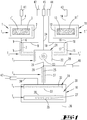
- Ein Ausführungsbeispiel der Erfindung wird nachfolgend anhand beigefügter Zeichnungen erläutert. Es zeigen:
- Fig. 1
- eine schematische Darstellung einer erfindungsgemäßen Vorrichtung,
- Fig. 2
- schematisch den Temperaturverlauf innerhalb des Gasleitungssystems vom Verdampfer 1 zum Suszeptor 35 und
- Fig. 3
- schematisch das Steuerungswerk der Vorrichtung.
- Die in der
Figur 1 lediglich schematisch dargestellte Vorrichtung besitzt einen Reaktor 10, bei dem es sich um ein gasdicht nach außen abgeschlossenes Gehäuse handelt. Das Gehäuse ist mittels einer Ableitung 36, die an eine Pumpe angeschlossen ist, evakuierbar. Innerhalb des Reaktors 10 befindet sich ein aus Metall bestehender Suszeptor 35, in dem Kühlkanäle 27 angeordnet sind, mit denen die Oberseite des als Kühlblock ausgestalteten Suszeptors 35 auf eine Suszeptortemperatur T6 von -50 bis 10°C temperierbar ist. Die Oberseite des Suszeptors 35 bildet den Boden einer Prozesskammer 30, auf dem ein oder mehrere Substrate 20 angeordnet sind. Die Decke der Prozesskammer 30 wird von einer Gasaustrittsfläche eines Gaseinlassorganes 31 ausgebildet. Die Gasaustrittsfläche des Gaseinlassorganes 31 besitzt eine Vielzahl von siebartig und gleichmäßig über die gesamte Gasaustrittsfläche verteilten Gasaustrittsöffnungen 33, aus denen ein Prozessgas in die Prozesskammer 30 einströmen kann. Das Gaseinlassorgan 31 kann duschkopfartig ausgebildet sein. - Das Prozessgas beinhaltet einen gasförmigen Ausgangsstoff, der mit einer Temperatur T5, die oberhalb seines Kondensationspunktes liegt, in die Prozesskammer 30 eingespeist wird. Die Temperatur der Oberfläche des Substrates 20 ist niedriger als die Kondensationstemperatur des gasförmigen Ausgangsstoffes, so dass der gasförmige Ausgangsstoff auf der Oberseite des Substrates 20 als Schicht kondensiert.
- Innerhalb des Gaseinlassorganes 31 ist eine Temperiereinrichtung 32 vorgesehen. Mit dieser Temperiereinrichtung 32, die beim Ausführungsbeispiel als Heizung ausgebildet ist, wird der gasförmige Ausgangsstoff auf die Temperatur T5 (Gaseinlasstemperatur) temperiert.
- Die Vorrichtung besitzt zumindest einen Quelle 1, in der ein fester oder flüssiger Ausgangsstoff 3 bereitgehalten wird. Der Ausgangsstoff 3 wird auf einer Quellentemperatur T1 gehalten, die größer ist als die Gaseinlasstemperatur T5. Der Ausgangsstoff 3 kann als poröser Körper, als Pulver oder dergleichen bevorratet sein. Der Ausgangsstoff kann aber auch eine Belegung auf einem porösen Körper sein. Es ist eine Quellentemperiereinrichtung 2 vorgesehen, bei der es sich um eine Heizung handelt. Mit der Heizung wird stetig Wärme in einen Verdampfer 1' eingespeist, der den Ausgangsstoff 3 beinhaltet, so dass der Ausgangsstoff 3 in die Gasform gebracht wird. Anstelle eines festen Ausgangsstoffes kann aber auch ein flüssiger Ausgangsstoff verwendet werden.
- In den Verdampfer 1' mündet eine Trägergaszuleitung 4. Mittels eines Massenflusscontrolers 41 wird ein Trägergasstrom in den Verdampfer 1' eingespeist. Es handelt sich dabei um Argon, Stickstoff, Wasserstoff oder ein anderes Inertgas. Der in die Gasform gewandelte Ausgangsstoff 3 wird durch einen Gasaustritt 6 aus dem Verdampfer 1' transportiert. Der Gausaustritt 6 ist mit einer Transportleitung 5 verbunden, so dass der gasförmige Ausgangsstoff aus dem Gasaustritt 6 in die Transportleitung 5 eingespeist werden kann. Unmittelbar stromabwärts des Gasaustritts 6 mündet eine Verdünnungszuleitung 8 in die sich daran anschließende Transportleitung 5. Durch die Verdünnungsgasleitung 8 wird ein Verdünnungsgas in die Gasleitung eingespeist. Der Massenfluss des in die Trägergaszuleitung eingespeisten Gases und der Massenfluss des in die Verdünnungsgasleitung 8 eingespeisten Gases wird durch Massenflusscontroler 41, 42 geregelt. Der den gasförmigen Ausgangsstoff transportierende Trägergasstrom mischt sich somit an der Einspeisestelle 9 mit dem Verdünnungsgasstrom, wobei es sich bei dem Verdünnungsgas um dasselbe Gas handelt, das auch den Trägergasstrom bildet.
- Die sich an die Einspeisestelle 9 anschließende Transportleitung 5 wird von einer Heizeinrichtung 7 beheizt. Diese Leitungstemperiereinrichtung 7 ist als Heizmanschette ausgebildet. Sie heizt die Transportleitung 5 auf eine Transportleitungstemperatur T2, die geringer ist als die Quellentemperatur Z1.
- Beim Ausführungsbeispiel ist eine zweite Prozessgasquelle 11 vorgesehen, die einen zweiten Verdampfer 11' aufweist, der ebenfalls mit einer Heizeinrichtung 12 versehen ist, mit der ein flüssiger oder fester Ausgangsstoff 13 auf eine zweite Quellentemperatur T1' temperiert wird. Auch hier mündet in den Verdampfer 11' eine Zuleitung 14, durch die ein mittels Massenflussmesser 43 kontrollierter Trägergasstrom in den Verdampfer 11' eingespeist wird. Das Trägergas transportiert den verdampften Ausgangsstoff durch einen Gasaustritt 16 aus dem Verdampfer 11' heraus.
- An einer Einspeisestelle 19 wird in den Gasstrom ein Verdünnungsgas eingespeist. Dies erfolgt mittels einer Verdünnungsgaszuleitung 18, durch die ein von einem Massenflusscontroler 44 gesteuerter Massenfluss eines Verdünnungsgases eingespeist wird.
- Stromabwärts der Einspeisestelle 19 erstreckt sich eine Transportleitung 15, die von einer Heizmanschette umgeben ist, die eine Leitungsheizung 17 ausbildet, mit der die Transportleitung 15 auf einer Leitungstemperatur T2' gehalten wird. Die Leitungstemperatur T2' ist geringer als die Qellentemperatur T1'. Der Ausgangsstoff 13 sind verschiedene organische Materialien.
- Die Transportleitung 5 und die Transportleitung 15 münden in eine Mischeinrichtung 21, in der Gasumlenkelemente 23 angeordnet sind, um die aus den Transportleitungen 5,15 in die Mischeinrichtung 21 eintretenden Gasmischungen miteinander zu vermischen.
- Innerhalb der Mischeinrichtung 21 ist eine Mischertemperiereinrichtung 22 vorgesehen. Es handelt sich hier um eine Heizeinrichtung, mit der die Mischeinrichtung 21 und insbesondere die Gasumlenkelemente 23 auf einer Mischertemperatur T3 gehalten werden. Die Mischertemperatur T3 ist geringer als die Leitungstemperaturen T2, T2'. Um zu vermeiden, dass der gasförmige Ausgangsstoff an den Gasumlenkflächen 23 kondensiert, wird das in die Mischeinrichtung 21 eintretende Gasgemisch, bestehend aus Trägergas und gasförmigem Ausgangsstoff, weiter verdünnt. Hierzu mündet stromaufwärts der Gasumlenkelemente 23 und insbesondere stromaufwärts der Heizeinrichtung 22 eine weitere Verdünnungsgaszuleitung 24 in die Mischkammer des Mischers 21. Der Verdünnungsgasstrom, der durch die Verdünnungsgaszuleitung 24 in die Mischkammer eingespeist wird, wird von einem Massenflusscontroler 45 gesteuert.
- Das in der Mischeinrichtung 21 gemischte Gasgemisch tritt durch einen Gasaustritt 26 aus der Mischeinrichtung 21 heraus. Dort befindet sich eine weitere Einspeisestelle 29, an der eine weitere Verdünnungsgaszuleitung 28 in den Gasstrom mündet. Durch die Verdünnungsgasleitung 28 wird ein weiterer Verdünnungsgasstrom, der von einem Massenflussregler 46 gesteuert ist, in den Gasstrom geleitet. Die Einspeisestelle 29 befindet sich unmittelbar stromabwärts des Gasaustritts 26.
- Die sich stromabwärts der Einspeisestelle 29 erstreckende Transportleitung 25 wird von einer Heizmanschette 27 auf eine Leitungstemperatur T4 aufgeheizt, die geringer ist als die Mischertemperatur T3 und größer ist als die Temperatur T5 innerhalb des Gaseinlassorgans 31.
- Die Transportleitung 25 mündet in das Gaseinlassorgan 31, in dem sich eine Heizeinrichtung 32 befindet. Stromaufwärts der Heizeinrichtung 32 mündet eine Verdünnungsgaszuleitung 34 in das Gaseinlassorgan 31, durch die ein weiterer Verdünnungsgasstrom, der von einem Massenflussregler 47 gesteuert ist, in das Gaseinlassorgan 31 eingespeist wird. Der in das Gaseinlassorgan 31 eingespeiste Gasstrom wird dadurch stromaufwärts der Heizeinrichtung 32 weiter verdünnt.
- Die schrittweise Verdünnung des gasförmigen Ausgangsstoffs in der Gasleitung zwischen Quelle 1, 11 bzw. Verdampfer 1', 11' und Gaseinlassorgan 31 führt zu einer schrittweisen Verminderung des Partialdrucks des gasförmigen Ausgangsstoffs bzw. der gasförmigen Ausgangsstoffe innerhalb des Gasleitungssystems in Strömungsrichtung. Dies ermöglicht den oben geschilderten Temperaturverlauf im Gastransportsystem, wie er in der
Figur 2 dargestellt ist, aus der hervorgeht, dass die Temperatur zwischen Quelle 1, 11 bzw. Verdampfer 1', Verdampfer 11' und Suszeptor 35 schrittweise absinkt, wobei der Temperaturverlauf in derFigur 2 lediglich qualitativ dargestellt ist. Der Temperaturunterschied zwischen den Temperaturen T5 und T6 kann größer sein als die übrigen Temperaturschritte. - Die
Figur 3 verdeutlicht die Steuerung. Die Vorrichtung besitzt eine Steuereinrichtung 38, mit der die Temperaturen T1, T2, T1', T2', T3, T4, T5 und T6 eingestellt werden können. Dies erfolgt mittels Reglern und Steuergliedern, die die Heizeinrichtungen 2, 7, 12, 17, 22, 27, 32 mit Heizleistung versorgen. Die Temperaturen T1, T2, T1', T2', T3, T4, T5 und T6 werden mittels Thermoelementen gemessen und der Steuereinrichtung 38 zur Regelung zur Verfügung gestellt. Die Steuereinrichtung versorgt die Kühleinrichtung 27 mit Kühlleistung. Ferner ist die Steuereinrichtung in der Lage, die Massenflusscontroler 41 - 47 anzusteuern, mit denen die Trägergasflüsse bzw. Verdünnungsgasflüsse geregelt werden. - Die vorstehenden Ausführungen dienen der Erläuterung der von der Anmeldung insgesamt erfassten Erfindungen, die den Stand der Technik zumindest durch die folgenden Merkmalskombinationen jeweils eigenständig weiterbilden, nämlich:
Eine Vorrichtung, die dadurch gekennzeichnet ist, dass die erste Verdünnungsgaszuleitung 8, 18 stromaufwärts der Leitungstemperiereinrichtung 7, 17 angeordnet ist und eine weitere Verdünnungsgaszuleitung 34 stromaufwärts der Gaseinlasstemperiereinrichtung 32 in das Gaseinlassorgan 31 mündet zur Einspeisung eines Verdünnungsgasstroms in das Gaseinlassorgan 31. - Eine Vorrichtung, die gekennzeichnet ist durch eine Steuereinrichtung, die so eingerichtet ist, dass die Quellentemperiereinrichtung 2, 12 auf die Quellentemperatur T1, T1', die Leitungstemperiereinrichtung 7, 17 auf die Leitungstemperatur T2, T2', die Gaseinlasstemperiereinrichtung 32 auf die Gaseinlasstemperatur T5 und die Suszeptortemperiereinrichtung 27 auf die Suszeptortemperatur T6 temperierbar sind.
- Ein Verfahren, das dadurch gekennzeichnet ist, dass die erste Verdünnungsgaszuleitung 8, 18 stromaufwärts der Leitungstemperiereinrichtung 7,17 angeordnet ist und durch eine weitere Verdünnungsgaszuleitung 34, die stromaufwärts der Gaseinlasstemperiereinrichtung 32 in das Gaseinlassorgan 31 mündet, ein Verdünnungsgasstrom in das Gaseinlassorgan 31 eingespeist wird.
- Eine Vorrichtung, die dadurch gekennzeichnet ist, dass die erste Quellentemperatur T1, T1' größer ist als die Leitungstemperatur T2, T2', die Leitungstemperatur T2, T2' größer ist als die Gaseinlasstemperatur T5 und die Gaseinlasstemperatur T5 größer ist als die eine Suszeptortemperatur T6
- Eine Vorrichtung, die gekennzeichnet ist durch eine einen zweiten Verdampfer 11' aufweisende Prozessgasquelle, in welchem zweiten Verdampfer 11' ein fester oder flüssiger zweiter Ausgangsstoff durch Zufuhr von mit einer zweiten Quellentemperiereinrichtung 12 erzeugten Wärme bei einer zweiten Quellentemperatur T1' in einen zweiten gasförmigen Ausgangsstoff verdampfbar ist, wobei in den zweiten Verdampfer 11' eine zweite Trägergaszuleitung 14 mündet zur Einspeisung eines zweiten Trägergasstroms zum Transport des zweiten gasförmigen Ausgangsstoffs aus dem zweiten Verdampfer 11' in eine zweite Transportleitung 15, wobei die zweite Transportleitung 15 mit einer zweiten Leitungstemperiereinrichtung 17 auf eine zweite Leitungstemperatur T2' temperiert wird und in die zweite Transportleitung 15 eine zweite Verdünnungsgaszuleitung 18 mündet, durch die ein zweiter Verdünnungsgasstrom in die zweite Transportleitung 18 eingespeist wird, wobei die erste Transportleitung 8 und die zweite Transportleitung 18 in einen Mischer 21 münden, der mittels einer Mischertemperiereinrichtung 22 auf eine Mischertemperatur T3 temperiert wird, wobei stromaufwärts der Mischertemperiereinrichtung 22 eine Verdünnungsgaszuleitung 24 in die Mischeinrichtung 21 mündet, mit der ein Verdünnungsgasstrom in die Mischeinrichtung 21 eingespeist wird.
- Ein Verfahren, das gekennzeichnet ist durch eine einen zweiten Verdampfer 11' aufweisende Prozessgasquelle, in welchem zweiten Verdampfer 11' ein fester oder flüssiger zweiter Ausgangsstoff durch Zufuhr von mit einer zweiten Quellentemperiereinrichtung 12 erzeugten Wärme bei einer zweiten Quellentemperatur T1' in einen zweiten gasförmigen Ausgangsstoff verdampft wird, wobei in den zweiten Verdampfer 11' eine zweite Trägergaszuleitung 14 mündet, in die ein zweiter Trägergasstrom eingespeist wird, mit dem der zweite gasförmige Ausgangsstoff aus dem zweiten Verdampfer 11' in eine zweite Transportleitung 15 transportiert wird, wobei die zweite Transportleitung 15 mit einer zweiten Leitungstemperiereinrichtung 17 auf eine zweite Leitungstemperatur T2' temperiert wird und in die zweite Transportleitung 15 eine zweite Verdünnungsgaszuleitung 18 mündet, durch die ein zweiter Verdünnungsgasstrom in die zweite Transportleitung 18 eingespeist wird, wobei die erste Transportleitung 8 und die zweite Transportleitung 18 in einen Mischer 21 münden, der mittels einer Mischertemperiereinrichtung 22 auf eine Mischertemperatur T3 temperiert wird, wobei stromaufwärts der Mischertemperiereinrichtung 22 eine Verdünnungsgaszuleitung 24 in die Mischeinrichtung 21 mündet, mit der ein Verdünnungsgasstrom in die Mischeinrichtung 21 eingespeist wird.
- Eine Vorrichtung, die dadurch gekennzeichnet ist, dass die Mischertemperatur T3 geringer ist als die erste und die zweite Leitungstemperatur T2, T2' und größer ist als die Gaseinlasstemperatur T5.
- Eine Vorrichtung, die gekennzeichnet ist durch einen stromabwärts der Mischeinrichtung 21 und stromaufwärts des Gaseinlassorgans 31 angeordnete Transportleitung 25 zum Transport des gasförmigen Ausgangsstoffs von der Mischeinrichtung 21 in das Gaseinlassorgan 31, welche mittels einer Leitungstemperiereinrichtung 27 auf eine Leitungstemperatur T4 temperierbar ist, wobei stromaufwärts der Leitungstemperiereinrichtung 27 eine Verdünnungsgaszuleitung 28 in die Transportleitung 25 mündet zur Einspeisung eines Verdünnungsgasstroms in die Transportleitung 25.
- Ein Verfahren, das gekennzeichnet ist durch einen stromabwärts der Mischeinrichtung 21 und stromaufwärts des Gaseinlassorgans 31 angeordnete Transportleitung 25 durch die der gasförmige Ausgangsstoff von der Mischeinrichtung 21 in das Gaseinlassorgan 31 transportiert wird, welche mittels einer Leitungstemperiereinrichtung 27 auf eine Leitungstemperatur T4 temperiert wird, wobei stromaufwärts der Leitungstemperiereinrichtung 27 eine Verdünnungsgaszuleitung 28 in die Transportleitung 25 mündet, mit der ein Verdünnungsgasstrom in die Transportleitung 25 eingespeist wird.
- Eine Vorrichtung, die dadurch gekennzeichnet ist, dass die Mischertemperatur T3 größer ist als die Leitungstemperatur T4 und die Leitungstemperatur T4 größer ist als die Gaseinlasstemperatur T5.
- Ein Verfahren, das dadurch gekennzeichnet ist, dass durch Einspeisen von einer Vielzahl von Verdünnungsgasströmen an verschiedenen, voneinander in Strömungsrichtung beabstandeten Stellen in eine beheizte Leitungsverbindung zwischen Verdampfer 1', 11' und Gaseinlassorgan 31 der Partialdruck des gasförmigen Ausgangsstoffes im Trägergasstrom schrittweise vermindert wird, wobei die Leitungsverbindung derart beheizt wird, dass an jeder Stelle der Leitungsverbindung die Temperatur im Gasstrom größer ist als die Kondensationstemperatur des gasförmigen Ausgangsstoffs.
Bezugszeichenliste: 1 Prozess gas quelle 26 Gasaustritt 1' Verdampfer 27 Temperiereinrichtung, Kühleinrichtung T4 2 Heizeinrichtung T1 28 Zuleitung 3 Ausgangsstoff 29 Einspeisestelle 4 Zuleitung 1 30 Prozesskammer 5 Transportleitung 31 Gaseinlassorgan 6 Gasaustritt 32 Heizeinrichtung T5 7 Heizeinrichtung T2 33 Gasaustrittsöffnung 8 Zuleitung 34 Zuleitung 5 9 Einspeisestelle 35 Suszeptor 10 CVD-Reaktor 36 Ableitung 11 Prozessgasquelle 37 Kühleinrichtung T6 11' Verdampfer 38 Steuereinrichtung 12 Heizeinrichtung T1' 39 -------------- 13 Ausgangsstoff 40 -------------- 14 Zuleitung 41 Massenflusscontroler Zul. 1 15 Transportleitung 42 Massenflusscontroler Zul. 2 16 Gasaustritt 43 Massenflusscontroler Zul. 1 17 Heizeinrichtung T2' 44 Massenflusscontroler Zul. 2 18 Zuleitung 45 Massenflusscontroler Zul. 3 19 Einspeisestelle 46 Massenflusscontroler Zul. 4 20 Substrat 47 Massenflusscontroler Zul. 5 21 Mischeinrichtung 22 Heizeinrichtung T3 T1 Quellentemperatur 23 Gaseinlasselement T2 Leitungstemperatur 24 Zuleitung 3 T3 Mischertemperatur 25 Transportleitung T4 Leitungstemperatur T5 Gaseintrittstemperatur T6 Depositionstemperatur Z1 Quellentemperatur
Claims (13)
- Vorrichtung zum Abscheiden ein oder mehrerer Schichten auf einem Substrat (20), mit einer einen Verdampfer (1', 11') aufweisenden Prozessgasquelle (1, 11), in welchem Verdampfer (1', 11') ein fester oder flüssiger Ausgangsstoff durch Zufuhr von mit einer Quellentemperiereinrichtung (2, 12) erzeugten Wärme bei einer Quellentemperatur (T1, T1') in einen gasförmigen Ausgangsstoff verdampfbar ist, wobei in den Verdampfer (1', 11') eine Trägergaszuleitung (4, 14) mündet, zur Einspeisung eines Trägergasstroms zum Transport des gasförmigen Ausgangsstoffs aus dem Verdampfer (1', 11') in eine erste Transportleitung (5, 15), wobei die erste Transportleitung (5,15) mit einer Leitungstemperiereinrichtung (7, 17) auf eine Leitungstemperatur (T2, T2') temperierbar ist, und in die erste Transportleitung (5,15) eine erste Verdünnungsgaszuleitung (8, 18) mündet, zur Einspeisung eines Verdünnungsgasstroms in die erste Transportleitung (5, 15), wobei die erste Verdünnungsgaszuleitung (8, 18) stromaufwärts der Leitungstemperiereinrichtung (7, 17) angeordnet ist, und mit einem mittels einer Gaseinlasstemperiereinrichtung (32) auf eine Gaseinlasstemperatur (T5) temperierbaren Gaseinlassorgan (31), das mit der ersten Transportleitung (8 ,18) leitungsverbunden ist, wobei eine weitere Verdünnungsgaszuleitung (34) stromaufwärts der Gaseinlasstemperiereinrichtung (32) in das Gaseinlassorgan (31) mündet zur Einspeisung eines Verdünnungsgasstroms in das Gaseinlassorgan (31), mit dem der gasförmige Ausgangsstoff in eine Prozesskammer (30) einspeisbar ist, die einen Suszeptor (35) aufweist, der mittels einer Suszeptortemperiereinrichtung (27) derart auf eine Suszeptortemperatur (T6) temperierbar ist, dass auf dem auf dem Suszeptor (35) aufliegenden Substrat (20) mittels des gasförmigen Ausgangsstoffes eine Schicht aufwächst, und eine Steuereinrichtung, die Quellentemperiereinrichtung (2, 12) auf die Quellentemperatur (T1, T1'), die Leitungstemperiereinrichtung (7, 17) auf die Leitungstemperatur (T2, T2'), die Gaseinlasstemperiereinrichtung (32) auf die Gaseinlasstemperatur (T5) und die Suszeptortemperiereinrichtung (27) auf die Suszeptortemperatur (T6) temperiert, dadurch gekennzeichnet, dass die Steuereinrichtung so eingerichtet ist, dass beim Abscheiden der Schicht die Quellentemperatur (T1, T1') größer ist als die Leitungstemperatur (T2, T2), die Leitungstemperatur (T2, T2') größer ist als die Gaseinlasstemperatur (T5) und die Gaseinlasstemperatur (T5) größer ist als die eine Suszeptortemperatur (T6).
- Verfahren zum Abscheiden ein oder mehrerer Schichten auf mindestens einem Substrat (20), mit einer einen Verdampfer (1', 11') aufweisenden Prozessgasquelle (1, 11), in welchem Verdampfer (1', 11') ein fester oder flüssiger Ausgangsstoff durch Zufuhr von mit einer Quellentemperiereinrichtung (2 ,12) erzeugten Wärme bei einer Quellentemperatur (T1, T1') in einen gasförmigen Ausgangsstoff verdampft wird, wobei in den Verdampfer (1', 11') eine Trägergaszuleitung (4, 14) mündet, in die ein erster Trägergasstrom eingespeist wird, mit dem der gasförmige Ausgangsstoff aus dem Verdampfer (1', 11') in eine erste Transportleitung (5, 15) transportiert wird, wobei die erste Transportleitung (5, 15) mit einer Leitungstemperiereinrichtung (7, 17) auf eine Leitungstemperatur (T2, T2') temperiert wird, und in die erste Transportleitung (5, 15) eine erste Verdünnungsgaszuleitung (8, 18) mündet, mit der ein Verdünnungsgasstrom in die erste Transportleitung (5, 15) eingespeist wird, wobei die erste Verdünnungsgaszuleitung (8, 18) stromaufwärts der Leitungstemperiereinrichtung (7, 17) angeordnet ist, und mit einem mittels einer Gaseinlasstemperiereinrichtung (32) auf eine Gaseinlasstemperatur (T5) temperierten Gaseinlassorgan (31), das mit der ersten Transportleitung (8, 18) leitungsverbunden ist, wobei eine weitere Verdünnungsgaszuleitung (34) stromaufwärts der Gaseinlasstemperiereinrichtung (32) in das Gaseinlassorgan (31) mündet zur Einspeisung eines Verdünnungsgasstroms in das Gaseinlassorgan (31), mit dem der gasförmige Ausgangsstoff in eine Prozesskammer (30) eingespeist wird, die einen Suszeptor (35) aufweist, der mittels einer Suszeptortemperiereinrichtung (27) auf eine Suszeptortemperatur (T6) temperiert wird, wobei auf dem auf dem Suszeptor (35) aufliegenden mindestens einem Substrat (20) mittels des gasförmigen Ausgangsstoffes eine Schicht abgeschieden wird, dadurch gekennzeichnet, dass beim Abscheiden der Schicht die Quellentemperatur (T1, T1') größer ist als die Leitungstemperatur (T2, T2'),die Leitungstemperatur (T2, T2') größer ist als die Gaseinlasstemperatur (T5) und die Gaseinlasstemperatur (T5) größer ist als die eine Suszeptortemperatur (T6).
- Vorrichtung nach Anspruch 1, gekennzeichnet durch eine einen zweiten Verdampfer (11') aufweisende Prozessgasquelle, in welchem zweiten Verdampfer (11') ein fester oder flüssiger zweiter Ausgangsstoff durch Zufuhr von mit einer zweiten Quellentemperiereinrichtung (12) erzeugten Wärme bei einer zweiten Quellentemperatur (T1') in einen zweiten gasförmigen Ausgangsstoff verdampfbar ist, wobei in den zweiten Verdampfer (11') eine zweite Trägergaszuleitung (14) mündet zur Einspeisung eines zweiten Trägergasstroms zum Transport des zweiten gasförmigen Ausgangsstoffs aus dem zweiten Verdampfer (11') in eine zweite Transportleitung (15), wobei die zweite Transportleitung (15) mit einer zweiten Leitungstemperiereinrichtung (17) auf eine zweite Leitungstemperatur (T2') temperiert wird und in die zweite Transportleitung (15) eine zweite Verdünnungsgaszuleitung (18) mündet, durch die ein zweiter Verdünnungsgasstrom in die zweite Transportleitung (18) eingespeist wird, wobei die erste Transportleitung (8) und die zweite Transportleitung (18) in einen Mischer (21) münden, der mittels einer Mischertemperiereinrichtung (22) auf eine Mischertemperatur (T3) temperiert wird, wobei stromaufwärts der Mischertemperiereinrichtung (22) eine Verdünnungsgaszuleitung (24) in die Mischeinrichtung (21) mündet, mit der ein Verdünnungsgasstrom in die Mischeinrichtung (21) eingespeist wird.
- Verfahren nach Anspruch 2, gekennzeichnet durch eine einen zweiten Verdampfer (11') aufweisende Prozessgasquelle, in welchem zweiten Verdampfer (11') ein fester oder flüssiger zweiter Ausgangsstoff durch Zufuhr von mit einer zweiten Quellentemperiereinrichtung (12) erzeugten Wärme bei einer zweiten Quellentemperatur (T1') in einen zweiten gasförmigen Ausgangsstoff verdampft wird, wobei in den zweiten Verdampfer (11') eine zweite Trägergaszuleitung (14) mündet, in die ein zweiter Trägergasstrom eingespeist wird, mit dem der zweite gasförmige Ausgangsstoff aus dem zweiten Verdampfer (11') in eine zweite Transportleitung (15) transportiert wird, wobei die zweite Transportleitung (15) mit einer zweiten Leitungstemperiereinrichtung (17) auf eine zweite Leitungstemperatur (T2') temperiert wird und in die zweite Transportleitung (15) eine zweite Verdünnungsgaszuleitung (18) mündet, durch die ein zweiter Verdünnungsgasstrom in die zweite Transportleitung (18) eingespeist wird, wobei die erste Transportleitung (8) und die zweite Transportleitung (18) in einen Mischer (21) münden, der mittels einer Mischertemperiereinrichtung (22) auf eine Mischertemperatur (T3) temperiert wird, wobei stromaufwärts der Mischertemperiereinrichtung (22) eine Verdünnungsgaszuleitung (24) in die Mischeinrichtung (21) mündet, mit der ein Verdünnungsgasstrom in die Mischeinrichtung (21) eingespeist wird.
- Vorrichtung nach Anspruch 3, dadurch gekennzeichnet, dass die Mischertemperatur (T3) geringer ist als die erste und die zweite Leitungstemperatur (T2, T2) und größer ist als die Gaseinlasstemperatur (T5).
- Verfahren nach Anspruch 4, dadurch gekennzeichnet, dass die Mischertemperatur (T3) geringer ist als die erste und die zweite Leitungstemperatur (T2, T2') und größer ist als die Gaseinlasstemperatur (T5).
- Vorrichtung nach Anspruch 3, gekennzeichnet durch einen stromabwärts der Mischeinrichtung (21) und stromaufwärts des Gaseinlassorgans (31) angeordnete Transportleitung (25) zum Transport des gasförmigen Ausgangsstoffs von der Mischeinrichtung (21) in das Gaseinlassorgan (31), welche mittels einer Leitungstemperiereinrichtung (27) auf eine Leitungstemperatur (T4) temperierbar ist, wobei stromaufwärts der Leitungstemperiereinrichtung (27) eine Verdünnungsgaszuleitung (28) in die Transportleitung (25) mündet zur Einspeisung eines Verdünnungsgasstroms in die Transportleitung (25).
- Verfahren nach Anspruch 4, gekennzeichnet durch einen stromabwärts der Mischeinrichtung (21) und stromaufwärts des Gaseinlassorgans (31) angeordnete Transportleitung (25) durch die der gasförmige Ausgangsstoff von der Mischeinrichtung (21) in das Gaseinlassorgan (31) transportiert wird, welche mittels einer Leitungstemperiereinrichtung (27) auf eine Leitungstemperatur (T4) temperiert wird, wobei stromaufwärts der Leitungstemperiereinrichtung (27) eine Verdünnungsgaszuleitung (28) in die Transportleitung (25) mündet, mit der ein Verdünnungsgasstrom in die Transportleitung (25) eingespeist wird.
- Vorrichtung nach einem der Ansprüche 3, 5 oder 7, dadurch gekennzeichnet, dass die Mischertemperatur (T3) größer ist als die Leitungstemperatur (T4) und die Leitungstemperatur (T4) größer ist als die Gaseinlasstemperatur (T5).
- Verfahren nach einem der Ansprüche 4, 6 oder 8, dadurch gekennzeichnet, dass die Mischertemperatur (T3) größer ist als die Leitungstemperatur (T4) und die Leitungstemperatur (T4) größer ist als die Gaseinlasstemperatur (T5).
- Verfahren nach einem der Ansprüche 2, 4, 6, 8 oder 10, dadurch gekennzeichnet, dass durch Einspeisen von einer Vielzahl von Verdünnungsgasströmen an verschiedenen, voneinander in Strömungsrichtung beabstandeten Stellen in eine beheizte Leitungsverbindung zwischen Verdampfer 1', 11') und Gaseinlassorgan (31) der Partialdruck des gasförmigen Ausgangsstoffes im Trägergasstrom schrittweise vermindert wird, wobei die Leitungsverbindung derart beheizt wird, dass an jeder Stelle der Leitungsverbindung die Temperatur im Gasstrom größer ist als die Kondensationstemperatur des gasförmigen Ausgangsstoffs.
- Vorrichtung nach einem der Ansprüche 1, 3, 5 oder 7, dadurch gekennzeichnet, dass die Schichten organische Schichten sind.
- Verfahren nach einem der Ansprüche 2, 4, 6, 8, 10 oder 11, dadurch gekennzeichnet, dass die Schichten organische Schichten sind.
Applications Claiming Priority (2)
| Application Number | Priority Date | Filing Date | Title |
|---|---|---|---|
| DE102014115497.5A DE102014115497A1 (de) | 2014-10-24 | 2014-10-24 | Temperierte Gaszuleitung mit an mehreren Stellen eingespeisten Verdünnungsgasströmen |
| PCT/EP2015/072669 WO2016062514A1 (de) | 2014-10-24 | 2015-10-01 | Temperierte gaszuleitung mit an mehreren stellen eingespeisten verdünnungsgasströmen |
Publications (2)
| Publication Number | Publication Date |
|---|---|
| EP3209809A1 EP3209809A1 (de) | 2017-08-30 |
| EP3209809B1 true EP3209809B1 (de) | 2018-12-05 |
Family
ID=54325520
Family Applications (1)
| Application Number | Title | Priority Date | Filing Date |
|---|---|---|---|
| EP15781046.6A Active EP3209809B1 (de) | 2014-10-24 | 2015-10-01 | Temperierte gaszuleitung mit an mehreren stellen eingespeisten verdünnungsgasströmen |
Country Status (8)
| Country | Link |
|---|---|
| US (1) | US10472718B2 (de) |
| EP (1) | EP3209809B1 (de) |
| JP (1) | JP6688290B2 (de) |
| KR (1) | KR20170072906A (de) |
| CN (1) | CN107075660B (de) |
| DE (1) | DE102014115497A1 (de) |
| TW (1) | TWI668316B (de) |
| WO (1) | WO2016062514A1 (de) |
Families Citing this family (7)
| Publication number | Priority date | Publication date | Assignee | Title |
|---|---|---|---|---|
| DE102014115497A1 (de) * | 2014-10-24 | 2016-05-12 | Aixtron Se | Temperierte Gaszuleitung mit an mehreren Stellen eingespeisten Verdünnungsgasströmen |
| DE102016100625A1 (de) | 2016-01-15 | 2017-07-20 | Aixtron Se | Vorrichtung zum Bereitstellen eines Prozessgases in einer Beschichtungseinrichtung |
| CN112048711A (zh) * | 2019-06-06 | 2020-12-08 | 北京北方华创微电子装备有限公司 | 一种供气管路和气相沉积设备 |
| KR102723200B1 (ko) * | 2019-07-03 | 2024-10-29 | 주성엔지니어링(주) | 가스 공급 장치 및 이를 포함하는 기판 처리 장치 |
| JP7810514B2 (ja) * | 2019-08-21 | 2026-02-03 | エーエスエム・アイピー・ホールディング・ベー・フェー | 成膜原料混合ガス生成装置及び成膜装置 |
| CN116298128B (zh) * | 2023-03-22 | 2026-03-24 | 华中科技大学 | 一种高精度低温气态重金属发生装置及方法 |
| CN119372628B (zh) * | 2024-12-26 | 2025-03-18 | 中微半导体设备(上海)股份有限公司 | 一种半导体处理设备及其固态前驱体输送系统和输送方法 |
Family Cites Families (26)
| Publication number | Priority date | Publication date | Assignee | Title |
|---|---|---|---|---|
| JPH04295089A (ja) * | 1991-03-26 | 1992-10-20 | Kokusai Chodendo Sangyo Gijutsu Kenkyu Center | 酸化物超電導膜製造装置 |
| US5776254A (en) * | 1994-12-28 | 1998-07-07 | Mitsubishi Denki Kabushiki Kaisha | Apparatus for forming thin film by chemical vapor deposition |
| US5670218A (en) * | 1995-10-04 | 1997-09-23 | Hyundai Electronics Industries Co., Ltd. | Method for forming ferroelectric thin film and apparatus therefor |
| TW565626B (en) * | 1996-11-20 | 2003-12-11 | Ebara Corp | Liquid feed vaporization system and gas injection device |
| JP3582437B2 (ja) * | 1999-12-24 | 2004-10-27 | 株式会社村田製作所 | 薄膜製造方法及びそれに用いる薄膜製造装置 |
| WO2001057289A1 (de) * | 2000-02-04 | 2001-08-09 | Aixtron Ag | Vorrichtung und verfahren zum abscheiden einer oder mehrerer schichten auf ein substrat |
| DE10007059A1 (de) | 2000-02-16 | 2001-08-23 | Aixtron Ag | Verfahren und Vorrichtung zur Herstellung von beschichteten Substraten mittels Kondensationsbeschichtung |
| DE10212923A1 (de) | 2002-03-22 | 2004-01-08 | Aixtron Ag | Verfahren zum Beschichten eines Substrates und Vorrichtung zur Durchführung des Verfahrens |
| JP2004349439A (ja) * | 2003-05-22 | 2004-12-09 | Renesas Technology Corp | 基板処理装置 |
| DE102004021578A1 (de) * | 2003-09-17 | 2005-04-21 | Aixtron Ag | Verfahren und Vorrichtung zur Abscheidung von ein-oder mehrkomponentigen Schichten und Schichtfolgen unter Verwendung von nicht-kontinuierlicher Injektion von flüssigen und gelösten Ausgangssubstanzen über eine Mehrkanalinjektionseinheit |
| JP4502189B2 (ja) * | 2004-06-02 | 2010-07-14 | ルネサスエレクトロニクス株式会社 | 薄膜の形成方法および半導体装置の製造方法 |
| JP5358778B2 (ja) | 2005-09-20 | 2013-12-04 | 国立大学法人東北大学 | 成膜装置、蒸発治具、及び、測定方法 |
| JP5179739B2 (ja) * | 2006-09-27 | 2013-04-10 | 東京エレクトロン株式会社 | 蒸着装置、蒸着装置の制御装置、蒸着装置の制御方法および蒸着装置の使用方法 |
| US7586109B2 (en) * | 2007-01-25 | 2009-09-08 | Varian Semiconductor Equipment Associates, Inc. | Technique for improving the performance and extending the lifetime of an ion source with gas dilution |
| DE102007011589A1 (de) * | 2007-03-08 | 2008-09-11 | Schott Ag | Fördereinrichtung für Precursor |
| US7794788B2 (en) * | 2007-03-28 | 2010-09-14 | Tokyo Electron Limited | Method for pre-conditioning a precursor vaporization system for a vapor deposition process |
| DE102009003781A1 (de) * | 2008-06-03 | 2009-12-10 | Aixtron Ag | Verfahren zum Abscheiden eines dünnschichtigen Polymers in einer Niederdruckgasphase |
| DE102008026974A1 (de) * | 2008-06-03 | 2009-12-10 | Aixtron Ag | Verfahren und Vorrichtung zum Abscheiden dünner Schichten aus polymeren Para-Xylylene oder substituiertem Para-Xylylene |
| JP2011063850A (ja) * | 2009-09-17 | 2011-03-31 | Tokyo Electron Ltd | 成膜装置、成膜方法および記憶媒体 |
| KR101711504B1 (ko) | 2011-06-22 | 2017-03-02 | 아익스트론 에스이 | 기상 증착 시스템 및 공급 헤드 |
| DE102011051261A1 (de) * | 2011-06-22 | 2012-12-27 | Aixtron Se | Verfahren und Vorrichtung zum Abscheiden von OLEDs insbesondere Verdampfungsvorrichtung dazu |
| JP5652960B2 (ja) * | 2011-08-01 | 2015-01-14 | 株式会社フジキン | 原料気化供給装置 |
| US9523151B2 (en) * | 2014-02-21 | 2016-12-20 | Tokyo Electron Limited | Vaporizer unit with open cell core and method of operating |
| DE102014115497A1 (de) * | 2014-10-24 | 2016-05-12 | Aixtron Se | Temperierte Gaszuleitung mit an mehreren Stellen eingespeisten Verdünnungsgasströmen |
| JP6565645B2 (ja) * | 2015-12-02 | 2019-08-28 | 東京エレクトロン株式会社 | 原料ガス供給装置、原料ガス供給方法及び記憶媒体 |
| JP6242933B2 (ja) * | 2016-03-31 | 2017-12-06 | 株式会社日立国際電気 | 基板処理装置、半導体装置の製造方法およびプログラム |
-
2014
- 2014-10-24 DE DE102014115497.5A patent/DE102014115497A1/de not_active Withdrawn
-
2015
- 2015-10-01 WO PCT/EP2015/072669 patent/WO2016062514A1/de not_active Ceased
- 2015-10-01 JP JP2017518109A patent/JP6688290B2/ja not_active Expired - Fee Related
- 2015-10-01 EP EP15781046.6A patent/EP3209809B1/de active Active
- 2015-10-01 US US15/517,461 patent/US10472718B2/en active Active
- 2015-10-01 KR KR1020177012636A patent/KR20170072906A/ko not_active Ceased
- 2015-10-01 CN CN201580057372.0A patent/CN107075660B/zh active Active
- 2015-10-19 TW TW104134216A patent/TWI668316B/zh active
Non-Patent Citations (1)
| Title |
|---|
| None * |
Also Published As
| Publication number | Publication date |
|---|---|
| DE102014115497A1 (de) | 2016-05-12 |
| WO2016062514A1 (de) | 2016-04-28 |
| TW201623661A (zh) | 2016-07-01 |
| CN107075660B (zh) | 2019-06-04 |
| TWI668316B (zh) | 2019-08-11 |
| EP3209809A1 (de) | 2017-08-30 |
| US10472718B2 (en) | 2019-11-12 |
| CN107075660A (zh) | 2017-08-18 |
| KR20170072906A (ko) | 2017-06-27 |
| JP2017537220A (ja) | 2017-12-14 |
| JP6688290B2 (ja) | 2020-04-28 |
| US20180265984A1 (en) | 2018-09-20 |
Similar Documents
| Publication | Publication Date | Title |
|---|---|---|
| EP3209809B1 (de) | Temperierte gaszuleitung mit an mehreren stellen eingespeisten verdünnungsgasströmen | |
| EP2470684B1 (de) | Cvd-verfahren und cvd-reaktor | |
| EP1774057B1 (de) | Vorrichtung und verfahren zur chemischen gasphasenabscheidung mit hohem durchsatz | |
| EP1252363B1 (de) | Vorrichtung und verfahren zum abscheiden einer oder mehrerer schichten auf ein substrat | |
| DE69433656T2 (de) | Verfahren zum Einleiten reaktiven Gases in eine Substratbearbeitungsvorrichtung | |
| DE102011089501B4 (de) | Vorrichtung und Verfahren zum Verdampfen von Material aus einer Metallschmelze | |
| DE102014104218A1 (de) | CVD-Reaktor mit Vorlaufzonen-Temperaturregelung | |
| WO2012143257A1 (de) | Vorrichtung und verfahren zum abscheiden von halbleiterschichten mit hcl-zugabe zur unterdrückung parasitären wachstums | |
| EP4211290A2 (de) | Cvd-reaktor mit temperierbarem gaseinlassbereich | |
| WO2016000944A1 (de) | Vorrichtung und verfahren zum erzeugen eines dampfes aus mehreren flüssigen oder festen ausgangsstoffen für eine cvd- oder pvd-einrichtung | |
| WO2018166955A1 (de) | Verfahren und vorrichtung zur thermischen behandlung eines substrates | |
| DE69428485T2 (de) | Gas-Zuführungssystem zur Bildung von Ablagerungen ausgehend von flüssigen Ausgangsprodukten | |
| WO2018064694A1 (de) | Vorrichtung und verfahren zum aufbringen einer kohlenstoffschicht | |
| DE10212923A1 (de) | Verfahren zum Beschichten eines Substrates und Vorrichtung zur Durchführung des Verfahrens | |
| DE102006044626C5 (de) | Aufkohlungsbehandlungsvorrichtung und -verfahren | |
| DE102019217284A1 (de) | Dampfphasenabscheidungsvorrichtung | |
| DE19735399C2 (de) | Gasleitungssystem für einen Prozeßreaktor, insbesondere Vertikalofen, zur Behandlung von Wafern und Verfahren zur Behandlung von Wafern in einem Prozeßreaktor | |
| DE102023100077A1 (de) | Vorrichtung und Verfahren zum Behandeln von Substraten | |
| DE102006013801A1 (de) | Gaseinlassorgan mit gelochter Isolationsplatte | |
| DE102013109696B3 (de) | Beschichtungsverfahren und Beschichtungsvorrichtung | |
| EP3224385B1 (de) | Vorrichtung zum abscheiden einer schicht auf einem substrat | |
| WO2002101806A1 (de) | Verfahren und vorrichtung zur kurzzeitigen thermischen behandlung von flachen g egenständen | |
| EP4417730A1 (de) | Vorrichtung und verfahren zur versorgung einer anlage zur beschichtung von werkstücken mit für den beschichtungsprozess benötigten prozessgasen | |
| DE102015104307B4 (de) | Sputtervorrichtung zur Beschichtung eines Substrats | |
| DE112023004806T5 (de) | Gerät zur gasphasenabscheidung |
Legal Events
| Date | Code | Title | Description |
|---|---|---|---|
| STAA | Information on the status of an ep patent application or granted ep patent |
Free format text: STATUS: THE INTERNATIONAL PUBLICATION HAS BEEN MADE |
|
| PUAI | Public reference made under article 153(3) epc to a published international application that has entered the european phase |
Free format text: ORIGINAL CODE: 0009012 |
|
| STAA | Information on the status of an ep patent application or granted ep patent |
Free format text: STATUS: REQUEST FOR EXAMINATION WAS MADE |
|
| 17P | Request for examination filed |
Effective date: 20170505 |
|
| AK | Designated contracting states |
Kind code of ref document: A1 Designated state(s): AL AT BE BG CH CY CZ DE DK EE ES FI FR GB GR HR HU IE IS IT LI LT LU LV MC MK MT NL NO PL PT RO RS SE SI SK SM TR |
|
| AX | Request for extension of the european patent |
Extension state: BA ME |
|
| RIN1 | Information on inventor provided before grant (corrected) |
Inventor name: GERSDORFF, MARKUS Inventor name: LONG, MICHAEL Inventor name: DAUELSBERG, MARTIN Inventor name: PAGADALA GOPI, BASKAR |
|
| DAV | Request for validation of the european patent (deleted) | ||
| DAX | Request for extension of the european patent (deleted) | ||
| GRAP | Despatch of communication of intention to grant a patent |
Free format text: ORIGINAL CODE: EPIDOSNIGR1 |
|
| STAA | Information on the status of an ep patent application or granted ep patent |
Free format text: STATUS: GRANT OF PATENT IS INTENDED |
|
| INTG | Intention to grant announced |
Effective date: 20180425 |
|
| GRAS | Grant fee paid |
Free format text: ORIGINAL CODE: EPIDOSNIGR3 |
|
| GRAA | (expected) grant |
Free format text: ORIGINAL CODE: 0009210 |
|
| STAA | Information on the status of an ep patent application or granted ep patent |
Free format text: STATUS: THE PATENT HAS BEEN GRANTED |
|
| AK | Designated contracting states |
Kind code of ref document: B1 Designated state(s): AL AT BE BG CH CY CZ DE DK EE ES FI FR GB GR HR HU IE IS IT LI LT LU LV MC MK MT NL NO PL PT RO RS SE SI SK SM TR |
|
| REG | Reference to a national code |
Ref country code: GB Ref legal event code: FG4D Free format text: NOT ENGLISH |
|
| REG | Reference to a national code |
Ref country code: CH Ref legal event code: EP |
|
| REG | Reference to a national code |
Ref country code: AT Ref legal event code: REF Ref document number: 1073159 Country of ref document: AT Kind code of ref document: T Effective date: 20181215 |
|
| REG | Reference to a national code |
Ref country code: IE Ref legal event code: FG4D Free format text: LANGUAGE OF EP DOCUMENT: GERMAN |
|
| REG | Reference to a national code |
Ref country code: DE Ref legal event code: R096 Ref document number: 502015007138 Country of ref document: DE |
|
| REG | Reference to a national code |
Ref country code: NL Ref legal event code: FP |
|
| REG | Reference to a national code |
Ref country code: LT Ref legal event code: MG4D |
|
| PG25 | Lapsed in a contracting state [announced via postgrant information from national office to epo] |
Ref country code: ES Free format text: LAPSE BECAUSE OF FAILURE TO SUBMIT A TRANSLATION OF THE DESCRIPTION OR TO PAY THE FEE WITHIN THE PRESCRIBED TIME-LIMIT Effective date: 20181205 Ref country code: LV Free format text: LAPSE BECAUSE OF FAILURE TO SUBMIT A TRANSLATION OF THE DESCRIPTION OR TO PAY THE FEE WITHIN THE PRESCRIBED TIME-LIMIT Effective date: 20181205 Ref country code: HR Free format text: LAPSE BECAUSE OF FAILURE TO SUBMIT A TRANSLATION OF THE DESCRIPTION OR TO PAY THE FEE WITHIN THE PRESCRIBED TIME-LIMIT Effective date: 20181205 Ref country code: BG Free format text: LAPSE BECAUSE OF FAILURE TO SUBMIT A TRANSLATION OF THE DESCRIPTION OR TO PAY THE FEE WITHIN THE PRESCRIBED TIME-LIMIT Effective date: 20190305 Ref country code: LT Free format text: LAPSE BECAUSE OF FAILURE TO SUBMIT A TRANSLATION OF THE DESCRIPTION OR TO PAY THE FEE WITHIN THE PRESCRIBED TIME-LIMIT Effective date: 20181205 Ref country code: NO Free format text: LAPSE BECAUSE OF FAILURE TO SUBMIT A TRANSLATION OF THE DESCRIPTION OR TO PAY THE FEE WITHIN THE PRESCRIBED TIME-LIMIT Effective date: 20190305 |
|
| PG25 | Lapsed in a contracting state [announced via postgrant information from national office to epo] |
Ref country code: SE Free format text: LAPSE BECAUSE OF FAILURE TO SUBMIT A TRANSLATION OF THE DESCRIPTION OR TO PAY THE FEE WITHIN THE PRESCRIBED TIME-LIMIT Effective date: 20181205 Ref country code: AL Free format text: LAPSE BECAUSE OF FAILURE TO SUBMIT A TRANSLATION OF THE DESCRIPTION OR TO PAY THE FEE WITHIN THE PRESCRIBED TIME-LIMIT Effective date: 20181205 Ref country code: GR Free format text: LAPSE BECAUSE OF FAILURE TO SUBMIT A TRANSLATION OF THE DESCRIPTION OR TO PAY THE FEE WITHIN THE PRESCRIBED TIME-LIMIT Effective date: 20190306 Ref country code: RS Free format text: LAPSE BECAUSE OF FAILURE TO SUBMIT A TRANSLATION OF THE DESCRIPTION OR TO PAY THE FEE WITHIN THE PRESCRIBED TIME-LIMIT Effective date: 20181205 |
|
| PG25 | Lapsed in a contracting state [announced via postgrant information from national office to epo] |
Ref country code: PT Free format text: LAPSE BECAUSE OF FAILURE TO SUBMIT A TRANSLATION OF THE DESCRIPTION OR TO PAY THE FEE WITHIN THE PRESCRIBED TIME-LIMIT Effective date: 20190405 Ref country code: IT Free format text: LAPSE BECAUSE OF FAILURE TO SUBMIT A TRANSLATION OF THE DESCRIPTION OR TO PAY THE FEE WITHIN THE PRESCRIBED TIME-LIMIT Effective date: 20181205 Ref country code: CZ Free format text: LAPSE BECAUSE OF FAILURE TO SUBMIT A TRANSLATION OF THE DESCRIPTION OR TO PAY THE FEE WITHIN THE PRESCRIBED TIME-LIMIT Effective date: 20181205 Ref country code: PL Free format text: LAPSE BECAUSE OF FAILURE TO SUBMIT A TRANSLATION OF THE DESCRIPTION OR TO PAY THE FEE WITHIN THE PRESCRIBED TIME-LIMIT Effective date: 20181205 |
|
| PG25 | Lapsed in a contracting state [announced via postgrant information from national office to epo] |
Ref country code: IS Free format text: LAPSE BECAUSE OF FAILURE TO SUBMIT A TRANSLATION OF THE DESCRIPTION OR TO PAY THE FEE WITHIN THE PRESCRIBED TIME-LIMIT Effective date: 20190405 Ref country code: SK Free format text: LAPSE BECAUSE OF FAILURE TO SUBMIT A TRANSLATION OF THE DESCRIPTION OR TO PAY THE FEE WITHIN THE PRESCRIBED TIME-LIMIT Effective date: 20181205 Ref country code: RO Free format text: LAPSE BECAUSE OF FAILURE TO SUBMIT A TRANSLATION OF THE DESCRIPTION OR TO PAY THE FEE WITHIN THE PRESCRIBED TIME-LIMIT Effective date: 20181205 Ref country code: EE Free format text: LAPSE BECAUSE OF FAILURE TO SUBMIT A TRANSLATION OF THE DESCRIPTION OR TO PAY THE FEE WITHIN THE PRESCRIBED TIME-LIMIT Effective date: 20181205 Ref country code: SM Free format text: LAPSE BECAUSE OF FAILURE TO SUBMIT A TRANSLATION OF THE DESCRIPTION OR TO PAY THE FEE WITHIN THE PRESCRIBED TIME-LIMIT Effective date: 20181205 |
|
| REG | Reference to a national code |
Ref country code: DE Ref legal event code: R097 Ref document number: 502015007138 Country of ref document: DE |
|
| PLBE | No opposition filed within time limit |
Free format text: ORIGINAL CODE: 0009261 |
|
| STAA | Information on the status of an ep patent application or granted ep patent |
Free format text: STATUS: NO OPPOSITION FILED WITHIN TIME LIMIT |
|
| PG25 | Lapsed in a contracting state [announced via postgrant information from national office to epo] |
Ref country code: SI Free format text: LAPSE BECAUSE OF FAILURE TO SUBMIT A TRANSLATION OF THE DESCRIPTION OR TO PAY THE FEE WITHIN THE PRESCRIBED TIME-LIMIT Effective date: 20181205 Ref country code: DK Free format text: LAPSE BECAUSE OF FAILURE TO SUBMIT A TRANSLATION OF THE DESCRIPTION OR TO PAY THE FEE WITHIN THE PRESCRIBED TIME-LIMIT Effective date: 20181205 |
|
| 26N | No opposition filed |
Effective date: 20190906 |
|
| PG25 | Lapsed in a contracting state [announced via postgrant information from national office to epo] |
Ref country code: TR Free format text: LAPSE BECAUSE OF FAILURE TO SUBMIT A TRANSLATION OF THE DESCRIPTION OR TO PAY THE FEE WITHIN THE PRESCRIBED TIME-LIMIT Effective date: 20181205 |
|
| REG | Reference to a national code |
Ref country code: FI Ref legal event code: MAE |
|
| PG25 | Lapsed in a contracting state [announced via postgrant information from national office to epo] |
Ref country code: MC Free format text: LAPSE BECAUSE OF FAILURE TO SUBMIT A TRANSLATION OF THE DESCRIPTION OR TO PAY THE FEE WITHIN THE PRESCRIBED TIME-LIMIT Effective date: 20181205 |
|
| REG | Reference to a national code |
Ref country code: CH Ref legal event code: PL |
|
| REG | Reference to a national code |
Ref country code: NL Ref legal event code: MM Effective date: 20191101 |
|
| PG25 | Lapsed in a contracting state [announced via postgrant information from national office to epo] |
Ref country code: FI Free format text: LAPSE BECAUSE OF NON-PAYMENT OF DUE FEES Effective date: 20191001 Ref country code: LU Free format text: LAPSE BECAUSE OF NON-PAYMENT OF DUE FEES Effective date: 20191001 Ref country code: CH Free format text: LAPSE BECAUSE OF NON-PAYMENT OF DUE FEES Effective date: 20191031 Ref country code: LI Free format text: LAPSE BECAUSE OF NON-PAYMENT OF DUE FEES Effective date: 20191031 |
|
| REG | Reference to a national code |
Ref country code: BE Ref legal event code: MM Effective date: 20191031 |
|
| PG25 | Lapsed in a contracting state [announced via postgrant information from national office to epo] |
Ref country code: NL Free format text: LAPSE BECAUSE OF NON-PAYMENT OF DUE FEES Effective date: 20191101 Ref country code: BE Free format text: LAPSE BECAUSE OF NON-PAYMENT OF DUE FEES Effective date: 20191031 |
|
| GBPC | Gb: european patent ceased through non-payment of renewal fee |
Effective date: 20191001 |
|
| PG25 | Lapsed in a contracting state [announced via postgrant information from national office to epo] |
Ref country code: GB Free format text: LAPSE BECAUSE OF NON-PAYMENT OF DUE FEES Effective date: 20191001 Ref country code: IE Free format text: LAPSE BECAUSE OF NON-PAYMENT OF DUE FEES Effective date: 20191001 Ref country code: FR Free format text: LAPSE BECAUSE OF NON-PAYMENT OF DUE FEES Effective date: 20191031 |
|
| PG25 | Lapsed in a contracting state [announced via postgrant information from national office to epo] |
Ref country code: CY Free format text: LAPSE BECAUSE OF FAILURE TO SUBMIT A TRANSLATION OF THE DESCRIPTION OR TO PAY THE FEE WITHIN THE PRESCRIBED TIME-LIMIT Effective date: 20181205 |
|
| PG25 | Lapsed in a contracting state [announced via postgrant information from national office to epo] |
Ref country code: MT Free format text: LAPSE BECAUSE OF FAILURE TO SUBMIT A TRANSLATION OF THE DESCRIPTION OR TO PAY THE FEE WITHIN THE PRESCRIBED TIME-LIMIT Effective date: 20181205 Ref country code: HU Free format text: LAPSE BECAUSE OF FAILURE TO SUBMIT A TRANSLATION OF THE DESCRIPTION OR TO PAY THE FEE WITHIN THE PRESCRIBED TIME-LIMIT; INVALID AB INITIO Effective date: 20151001 |
|
| REG | Reference to a national code |
Ref country code: AT Ref legal event code: MM01 Ref document number: 1073159 Country of ref document: AT Kind code of ref document: T Effective date: 20201001 |
|
| PG25 | Lapsed in a contracting state [announced via postgrant information from national office to epo] |
Ref country code: AT Free format text: LAPSE BECAUSE OF NON-PAYMENT OF DUE FEES Effective date: 20201001 |
|
| PG25 | Lapsed in a contracting state [announced via postgrant information from national office to epo] |
Ref country code: MK Free format text: LAPSE BECAUSE OF FAILURE TO SUBMIT A TRANSLATION OF THE DESCRIPTION OR TO PAY THE FEE WITHIN THE PRESCRIBED TIME-LIMIT Effective date: 20181205 |
|
| P01 | Opt-out of the competence of the unified patent court (upc) registered |
Effective date: 20230528 |
|
| PGFP | Annual fee paid to national office [announced via postgrant information from national office to epo] |
Ref country code: DE Payment date: 20241121 Year of fee payment: 10 |