EP3209993B1 - Verfahren und vorrichtung zur überwachung von einer flugzeugsturbineschaufel durch messung einer gleichgewichtposition - Google Patents
Verfahren und vorrichtung zur überwachung von einer flugzeugsturbineschaufel durch messung einer gleichgewichtposition Download PDFInfo
- Publication number
- EP3209993B1 EP3209993B1 EP15793872.1A EP15793872A EP3209993B1 EP 3209993 B1 EP3209993 B1 EP 3209993B1 EP 15793872 A EP15793872 A EP 15793872A EP 3209993 B1 EP3209993 B1 EP 3209993B1
- Authority
- EP
- European Patent Office
- Prior art keywords
- blade
- interest
- aircraft
- flight phase
- positions
- Prior art date
- Legal status (The legal status is an assumption and is not a legal conclusion. Google has not performed a legal analysis and makes no representation as to the accuracy of the status listed.)
- Active
Links
Images

Classifications
-
- G—PHYSICS
- G01—MEASURING; TESTING
- G01M—TESTING STATIC OR DYNAMIC BALANCE OF MACHINES OR STRUCTURES; TESTING OF STRUCTURES OR APPARATUS, NOT OTHERWISE PROVIDED FOR
- G01M15/00—Testing of engines
- G01M15/14—Testing gas-turbine engines or jet-propulsion engines
-
- G—PHYSICS
- G01—MEASURING; TESTING
- G01H—MEASUREMENT OF MECHANICAL VIBRATIONS OR ULTRASONIC, SONIC OR INFRASONIC WAVES
- G01H1/00—Measuring characteristics of vibrations in solids by using direct conduction to the detector
- G01H1/003—Measuring characteristics of vibrations in solids by using direct conduction to the detector of rotating machines
- G01H1/006—Measuring characteristics of vibrations in solids by using direct conduction to the detector of rotating machines of the rotor of turbo machines
-
- G—PHYSICS
- G01—MEASURING; TESTING
- G01H—MEASUREMENT OF MECHANICAL VIBRATIONS OR ULTRASONIC, SONIC OR INFRASONIC WAVES
- G01H3/00—Measuring characteristics of vibrations by using a detector in a fluid
-
- G—PHYSICS
- G01—MEASURING; TESTING
- G01H—MEASUREMENT OF MECHANICAL VIBRATIONS OR ULTRASONIC, SONIC OR INFRASONIC WAVES
- G01H3/00—Measuring characteristics of vibrations by using a detector in a fluid
- G01H3/04—Frequency
- G01H3/08—Analysing frequencies present in complex vibrations, e.g. comparing harmonics present
-
- G—PHYSICS
- G05—CONTROLLING; REGULATING
- G05B—CONTROL OR REGULATING SYSTEMS IN GENERAL; FUNCTIONAL ELEMENTS OF SUCH SYSTEMS; MONITORING OR TESTING ARRANGEMENTS FOR SUCH SYSTEMS OR ELEMENTS
- G05B23/00—Testing or monitoring of control systems or parts thereof
- G05B23/02—Electric testing or monitoring
- G05B23/0205—Electric testing or monitoring by means of a monitoring system capable of detecting and responding to faults
- G05B23/0218—Electric testing or monitoring by means of a monitoring system capable of detecting and responding to faults characterised by the fault detection method dealing with either existing or incipient faults
- G05B23/0224—Process history based detection method, e.g. whereby history implies the availability of large amounts of data
- G05B23/0227—Qualitative history assessment, whereby the type of data acted upon, e.g. waveforms, images or patterns, is not relevant, e.g. rule based assessment; if-then decisions
- G05B23/0235—Qualitative history assessment, whereby the type of data acted upon, e.g. waveforms, images or patterns, is not relevant, e.g. rule based assessment; if-then decisions based on a comparison with predetermined threshold or range, e.g. "classical methods", carried out during normal operation; threshold adaptation or choice; when or how to compare with the threshold
-
- G—PHYSICS
- G05—CONTROLLING; REGULATING
- G05B—CONTROL OR REGULATING SYSTEMS IN GENERAL; FUNCTIONAL ELEMENTS OF SUCH SYSTEMS; MONITORING OR TESTING ARRANGEMENTS FOR SUCH SYSTEMS OR ELEMENTS
- G05B2219/00—Program-control systems
- G05B2219/30—Nc systems
- G05B2219/45—Nc applications
- G05B2219/45071—Aircraft, airplane, ship cleaning manipulator, paint stripping
Definitions
- the present invention relates to the field of monitoring a bladed wheel of an aircraft engine. Such monitoring is implemented for example to detect damage to a blade of the wheel.
- An aircraft engine has several padded wheels.
- a bladed wheel can be degraded, for example following an impact of an object against a blade of the wheel, or following a change in the aerodynamic conditions to which the bladed wheel is subjected.
- An object of the present invention is to provide a method and a device for monitoring a bladed wheel of an aircraft engine, making it possible to quickly detect damage to a blade using a reduced number of sensors.
- the dynamic component corresponds to a vibration of the blade around a central position called the equilibrium position.
- the static component corresponding to an offset from this equilibrium position.
- the idea behind the invention consists in detecting the damage of a blade by no longer focusing on the dynamic component of the movement of this blade, but only on its static component.
- the figure 1 illustrates schematically a first embodiment of the method according to the invention, implemented for monitoring a paddle wheel of an aircraft engine.
- steps are implemented in turn during each of the flights in said series of flights. For each flight, these steps are implemented for one or more predetermined flight phase (s) by appraisal during a prior step of the method according to the invention.
- a predetermined flight phase corresponds, at the level of each blade, to a static pressure on the blade and to a speed of rotation of this blade which induce a critical operating mode of the blade.
- critical flight phases are determined as a function of the engine operating parameters (range of rotation speed of the bladed wheel for example) and of the engine environment parameters (temperature, altitude for example). This determination is made by experts.
- the predetermined flight phases which may in particular include an acceleration phase, a deceleration phase, a thrust reversal (or reverse) phase.
- the predetermined flight phases are detected in the current flight phases as a function of the operating parameters of the engine or of its environment.
- a predetermined flight phase is associated with at least part of each time signal.
- the method may include detection of the start and end of the predetermined flight phase, so as to control the recording of the time signal only between these two instants.
- the method can comprise a selection of at least part of an acquired and recorded time signal, this part corresponding to said predetermined flight phase.
- each average position is therefore associated with a blade, a flight, and a flight phase.
- the mean position of a blade designates a position of a fixed point of the blade, relative to a reference, and time averaged.
- the fixed point here is the top of the blade, that is to say the end of the blade opposite the center of rotation of the bladed wheel.
- the instantaneous position of the top of a blade is the position of this point, measured by a sensor and for a given rotation of the bladed wheel
- the average position of the top of a blade is the average of several instantaneous positions, measured for different rotations of the bladed wheel, and by one or more sensors.
- the position is in particular an angular position, on a disc centered on the center of rotation of the bladed wheel.
- Time average is achieved over a small time interval, for example less than 2 minutes.
- the time average can be carried out over a single time interval, or over several discontinuous time intervals all relating to the same flight and to the same flight phase.
- the time average is carried out over 5 to 10 time intervals each of a duration between 1 s and 30 s, for example 10 s.
- the average position of a blade is also called the equilibrium position of the blade, and forms a first position of interest, denoted PI1.
- the equilibrium position of a blade is therefore an indicator making it possible to quickly and easily detect the appearance of damage on a blade. No attempt is made to know the frequency of vibration of the blade. This overcomes the limitations and difficulties of the prior art, in particular relating to the use of a large number of sensors distributed throughout the rotation circumference of the blade, for example on an internal surface of a casing or fairing.
- the figure 2A illustrates schematically the acquisition of a time signal relating to instants of passage of the blades of an aircraft engine in front of a sensor.
- FIG 2A We illustrated in figure 2A the case of a single sensor 21, disposed at the periphery of a bladed wheel 22 having here five blades 23.
- the bladed wheel can be that of a blower, a high pressure compressor, or any other element of a aircraft engine.
- the invention is however not limited to such an arrangement, and may involve several sensors, for example at least three sensors.
- the several sensors are then advantageously distributed irregularly on a casing surrounding the wheel.
- the sensor 21 can be an eddy current sensor, or a capacitive, or optical type sensor, or any other robust, precise, and space-saving sensor. Such a sensor is called a “tip-timing” sensor, because it detects moments of passage relative to a time base.
- the sensor 21 is disposed at the periphery of the bladed wheel 22, and points towards the center of rotation of the bladed wheel 22. It detects the passage of the tips of the blades 23 and identifies the instants of passage relative to a time base.
- a blade vibrates for example between two extreme positions 24A and 24B, between which is its equilibrium position 24C.
- the figure 2B illustrates the time signal 24 acquired by the sensor 21 of the figure 2A .
- the abscissa axis is a time axis.
- Y-axis corresponds to an amplitude.
- the time difference between two pulses 25 corresponds to a distance between the vertices of two adjacent blades, these two quantities being connected by the speed of rotation of the bladed wheel .
- the bladed wheel, or the rotor which drives it in rotation may have a mark detectable by the sensor 21, so that it is possible to discriminate the pulses relating to different turns of the wheel.
- This reference can also be used to calibrate the time signal and to link time differences between pulses to angular differences. Knowing that there are 360 ° between two successive detections of the reference frame, it is possible to convert time intervals into angular deviations. We can also deduce the speed of rotation of the bladed wheel.
- a tone wheel instead of a marker on the bladed wheel or on its rotor, a tone wheel arranged to rotate at the same speed as the bladed wheel is used, and a revolution counter which detects the passage of a marker on the tone wheel.
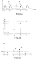
- FIGS 3A to 3C illustrate the measurement of an equilibrium position of a blade, from a time signal of the type represented in figure 2B .
- This measurement implements, for each blade, the application of low frequency filtering on a time signal representative of the movement carried out by the blade.
- the figure 3A illustrates a time signal 34, obtained by synchronizing and combining the time signals each acquired by a sensor, and by selecting only the pulses 35 relating to one of the blades.
- the measurements made by different sensors can be combined knowing the positions of the sensors relative to each other.
- the figure 3B illustrates a graph in which the absolute times t 1 , t 2 , t 3 and t 4 are represented as a function of a reduced time.
- the reduced time corresponds to the time reduced by the speed of rotation of the bladed wheel. This involves correcting the temporal measurements of the effect of a variation in the speed of rotation, from one revolution to the other of the bladed wheel.
- the figure 3C corresponds to the figure 3B , in which the ordinates of the points are corrected for the rotation of the wheel.
- each pulse 35 of the figure 3A corresponds to one wheel revolution.
- each point of the figure 3B corresponds to one wheel revolution.
- the duration for the wheel to rotate 360 ° is deduced from the speed of rotation of the wheel. We subtract from times t 1 , t 2 , t 3 and t 4 the adapted multiples of this duration, so as to overcome the effect of the rotation of the wheel on the measurements t 1 , t 2 , t 3 and t 4 .
- a series of points 36 is thus obtained illustrating the various positions of the blade, taken at each of the turns of the bladed wheel. These positions here correspond to times, but we could also express these positions for example in units of angles, these two concepts being linked by the speed of rotation of the bladed wheel.
- the equilibrium position of the blade is defined by the average value T eq between these different positions. These different positions can define an oscillatory signal, representative of the movement of the blade during the period of measurement of these positions.
- the equilibrium position corresponds to the continuous component (very low frequency) of this oscillatory signal.
- the equilibrium position can be obtained using simple low-pass filtering of this oscillatory signal.
- the equilibrium position can be expressed in units of time or in units of angles. By convention, an equilibrium position is negative in the direction of rotation of the wheel, seen from the front of the aircraft.
- a sub-sampling of the movement actually carried out by the blade does not allow access to the frequency of the blade's oscillation.
- Sub-sampling of the movement actually performed by the blade can result in a bias (constant offset) between the actual equilibrium position of the blade and the measured equilibrium position.
- a bias constant offset
- the invention does not implement heavy data processing: one can be content with acquiring an undersampled signal, and the main data processing to be carried out is simple low-pass filtering.
- the invention therefore offers a means of rapid and inexpensive detection in terms of on-board computing power for damage to a blade.
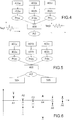
- the figure 4 schematically illustrates a second embodiment of the method according to the invention.
- Steps 401a, 402a correspond to steps 101 and 102 of the figure 1 , implemented for a first flight.
- the first position of interest PI1a is obtained for each blade, corresponding to the equilibrium position of the blade associated with this first flight and with said predetermined flight phase.
- the oscillatory signal corresponding to the movement of a blade during this first flight and for said predetermined flight phase.
- the average value of this oscillatory signal is T eq1 , which corresponds to the first position of interest PI1a.
- Steps 401b, 402b correspond to steps 101 and 102 of the figure 1 , implemented for a second flight.
- the first position of interest PI1b is obtained for each blade, corresponding to this second flight and to said predetermined flight phase.
- Steps 401c, 402c correspond to steps 101 and 102 of the figure 1 , implemented for a third flight.
- the first position of interest PI1c is obtained for each blade, corresponding to this third flight and to said predetermined flight phase.
- the average value of this oscillatory signal is T eq3 , which corresponds to the third position of interest PI1c.
- the method then comprises a step 403 for calculating, for each blade, the average value of the first positions of interest previously measured. This average value is called the second position of interest PI2. There is therefore obtained, for each blade, and for said predetermined flight phase, an average value which integrates the measurements associated with several previous flights, to provide a single value which can be used immediately.
- the median value of said first positions of interest is calculated.
- the different flights considered are successive, the analysis being for example carried out every two or three flights.
- the flights considered are consecutive flights.
- the figure 5 schematically illustrates a third embodiment of the method according to the invention.
- the process illustrated in figure 5 differs from the process illustrated in figure 4 that in that it comprises additional steps using the second position of interest PI2, relating to several flights and to a predetermined flight phase.
- a step 504 the second position of interest PI2 and a reference position associated with said blade are compared for each blade and for said predetermined flight phase.
- the reference position associated with a blade can be a value obtained empirically, for example during one or more flights at the start of the life of the wheel, when it is known that the blade does not show any damage. It is thus very easy to get rid of the effect of a measurement bias.
- the reference position associated with a blade can be a theoretical value, imposed on the manufacturer. This theoretical value can be corrected for a possible measurement bias, so that it can be compared with positions of interest which are themselves measured.
- the reference positions of the blades preferably correspond to blades equi-distributed angularly over 360 °.
- the predetermined threshold can be obtained by correlation with other known techniques for detecting damage to a blade, or from measurements on blades of known damage.
- the predetermined threshold is preferably the same for all the blades.
- the predetermined threshold is preferably the same for all the predetermined flight phases, or at least the same for all the flight phases which are favorable for damage monitoring, namely those where the aerodynamic loading is the most important and where the mechanical stresses exerted on the structure of the blades are therefore the most important.
- step 505 a monitoring is carried out, for each blade and for said predetermined flight phase, of the values taken by the second position of interest PI2 during several sets of flights. It is thus possible to identify a progressive shift in the value taken by the second position of interest PI2 during the flights. This offset is representative of the progressive damage to the blade. For example, there is progressive wear of the blade.
- the invention thus makes it possible to detect the appearance of damage on a blade, this appearance being able to be sudden or progressive.
- the steps of comparing a position of interest to a reference position, and / or of tracking the values taken by a position of interest during the flights, can also be implemented on the first position of interest PI1 .
- the figure 6 illustrates measurements obtained using an advantageous embodiment of the method according to the invention.
- the abscissa axis is graduated in blade index. Here we have represented six blades indexed A1, A2, A3, A4, A5 and A6.
- the ordinate axis corresponds to equilibrium positions. It is graduated for example in angle unit.
- the null ordinate corresponds to the positions of the blades if they were angularly distributed.
- the figure 6 shows a box diagram in which there has been shown, for each blade and for two sets of flights, the first equilibrium positions associated with a predetermined flight phase.
- a first set of ten flights is represented by a solid line segment, and a second set of ten flights is represented by a dotted line segment.
- the two sets of flights are not consecutive.
- the first set of flights corresponds to the start of the bladed wheel's life.
- the second set of flights corresponds to the mid-life of the bladed wheel. For example, more than 1,500 flights separate the first and second flight sets.
- the high value corresponds to the maximum value of the equilibrium positions measured on the set of flights
- the low value corresponds to the minimum value of these same equilibrium positions
- the point corresponds to the average value of these same positions of equilibrium.
- the solid line segment is very far from the dotted line segment, which indicates the appearance of damage on the A4 blade between the two sets of flights studied.
- the dotted segment is much wider than the other segments of the figure 6 .
- This spreading corresponds to a loss of quality of the measurements. If we find this spread on all the blades, we can deduce the appearance of damage to the acquisition chain at the output of sensor 21. We can therefore look for an anomaly in the acquisition chain at output d '' a sensor, by measuring, for each blade, the evolution of the dispersion of the equilibrium positions associated with the same flight phase.
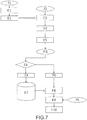
- FIG. 7 the steps implemented during a particular flight of the aircraft. The same steps are repeated for several flights of a series of flights from the aircraft. Preferably, on each flight, the same steps are implemented for several predetermined flight phases.
- step E1 the flight phase in which the aircraft is located is determined during the flight of an aircraft, from data 71.
- Data 71 includes in particular the speed of rotation of the monitored paddle wheel.
- step E2 the recording of a signal 72 is piloted, when it is detected that the aircraft is in a predetermined flight phase according to the invention.
- the recording of the signal 72 corresponds to step E3.
- the signal 72 corresponds to at least part of at least one time signal, each time signal being acquired by a sensor according to the invention.
- a sensor detects the instants of passage of the apices of the blades of the aircraft at a predetermined point.
- Step E3 also includes a matching of a signal part with a predetermined flight phase.
- each signal part is indexed to be associated with a predetermined flight phase.
- step E4 the signal 72 is used to deduce therefrom, for each blade and for a predetermined flight phase, a so-called elementary equilibrium position.
- This step corresponds to obtaining an equilibrium position as detailed with reference to Figures 3A to 3C .
- This step notably includes putting the signal parts in order to juxtapose them by blade and by flight phase, switching to a reduced time scale of the speed of rotation, etc.
- the signal parts can come from different sensors.
- the recording E3 of the signal 72 is carried out for a duration of a few seconds, for example 5 to 20 seconds, and repeated several times during the same predetermined flight phase, for example 5 to 20 times. This same predetermined flight phase can occur several times per flight.
- Each iteration of step E3 corresponds to an iteration of step E4, so that one obtains, for each blade and for the predetermined flight phase, several elementary equilibrium positions.
- steps E3 and E4 are not implemented consecutively. In other words, it is determined that the aircraft is in a first flight phase and a first elementary equilibrium position is calculated for each blade. A little later, it is detected that the aircraft is again in the first flight phase, and a second elementary equilibrium position is calculated for each blade.
- the time signal acquired by each sensor is recorded for the entire duration of the flight, and useful parts of the signal are subsequently selected.
- step E5 for each blade and for each predetermined flight phase, an average of the several elementary equilibrium positions thus obtained is calculated.
- the equilibrium position known as the first position of interest PI1 is obtained. It is a consolidated equilibrium position value.
- equilibrium position measurements which seem aberrant because they are too far from the other measurements, for the same blade, the same flight and the same flight phase.
- step E6 it is determined whether one is in learning configuration 73, or in detection configuration 74.
- the first positions of interest PI1 are stored in a database, during a storage step E7. They may constitute the reference positions each associated with a blade.
- step E6 is followed by a step E8 of analysis and comparison of data, with a view to determining, for each blade, whether it has damage.
- Step E8 uses the data stored in step E7. For example, this involves comparing, for each blade and for each predetermined flight phase, the consolidated equilibrium position (first position of interest) with a reference position. We obtain, at the end from step E8, for each blade and for each predetermined flight phase, a difference between a reference position and a first position of interest.
- step E9 for each blade, this difference is compared to a predetermined threshold 75 associated with said blade.
- step E10 and when this difference is greater than the predetermined threshold for at least one blade and at least one predetermined flight phase, an alert signal is issued identifying the blade and specifying, if necessary, the extent of the damage.
- the threshold can be the same whatever the flight phase.
- the thresholds can be identical for all the blades.
- the alert signal can specify whether the damage requires immediate repair of the bladed wheel, or whether a maintenance step must be scheduled within a fixed period because the bladed wheel simply shows signs of wear.
- steps E6 and following can be implemented on the ground, after transmission to a base on the ground of the equilibrium positions obtained in step E5. It is also possible to carry out steps E4 and E5 on the ground.
- the edge separation is a design choice. In all cases, we will seek to limit the number of calculations performed on-board, the amount of data to be transmitted and the amount of data to be stored on-board.
- Data exchanges can take place when the aircraft is in flight and a data exchange is possible with the ground.
- all of the data acquired during a flight is stored in a memory which is consulted by the base on the ground when the aircraft is on the ground, the memory then being emptied.
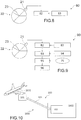
- the figure 8 very schematically illustrates a first embodiment of such a device 80.
- the device according to the invention comprises means 83 for determining which phase of flight the aircraft is in, for example from the speed of rotation of the monitored paddle wheel. This speed of rotation can be obtained by means of the sensor 21.
- Signal processing means 82 such as a computer or a computer, are connected to the sensor 21 to receive a time signal relating to instants of passage of the tips of the blades 23 in front of the sensor.
- the means 83 are also connected to the signal processing means 82.
- the signal processing means 82 are arranged to register the signal supplied by the sensor 21 only at appropriate times.
- These opportune moments, or time ranges of interest, depend on the phase or phases of predetermined flight (s) chosen to implement the method according to the invention. These opportune moments may also depend on the implementation of a consolidation of measures as defined with reference to the figure 7 , about step E5.
- Human-machine interface means can allow a human operator to define upstream the predetermined flight phase (s).
- the signal processing means 82 receive all of the signals acquired by the sensor 21 throughout each flight, and include means for selecting signal parts associated with ranges of interest.
- the signal processing means 82 are also arranged to index a recorded signal, so as to associate it with a predetermined flight phase.
- the signal processing means 82 are arranged to measure, for each blade, and for at least one predetermined flight phase, an equilibrium position of the blade.
- the means 82 notably comprise means for reconstruction, for each flight, for each blade and for each predetermined flight phase, of an oscillatory signal representative of the movement of the blade, and means for low-pass filtering of this signal.
- the means 82 implement in particular a method as described with reference to Figures 3A to 3C . If necessary, the signal processing means 82 implement a consolidation of the equilibrium position measurements, as described with reference to the figure 7 and about step E5.
- the signal processing means 82 provide at the output, for the flight considered, for each blade and for each predetermined flight phase, the equilibrium position called the first position of interest.
- the processing means 82 can also provide a list of several equilibrium positions of the blades, each associated with a predetermined flight and flight phase, said list being presented in the form of a box diagram as illustrated in figure 6 .
- the signal processing means 82 can comprise means for calculating an average or median value of different equilibrium positions of each blade, for the same flight phase and for several flights of a set of flights of the aircraft. .
- the signal processing means 82 can then output, for the set of flights considered, for each blade and for each predetermined flight phase, this mean or median value called the second position of interest.
- the signal processing means 82 can be connected to a memory (not shown), arranged to store the measured equilibrium positions. It is thus possible to monitor the evolution of the equilibrium positions during the flights.
- the figure 9 schematically illustrates a second embodiment of the device 90 according to the invention.
- the figure 9 will only be described for its differences in relation to the figure 8 .
- Comparison means 93 are connected at the input to the signal processing means 82, and to a database 94 storing reference positions.
- the comparison means 93 compare, for each blade and for each predetermined flight phase, the position of interest (first or second) provided by the signal processing means, and a reference position.
- the data stored in the database 94 can be obtained during an initial learning step.
- the comparison means 93 provide at the output, for each blade and for each predetermined flight phase, a difference between a position of interest and a reference position.
- Detection means 95 receive this difference as input, as well as the threshold 75 associated with said blade and with said flight phase (see figure 7 ).
- the thresholds can be stored in a dedicated database, or in the database 94. It can be the same threshold whatever the blade and the flight phase.
- Alert means 96 are arranged to emit an alert signal when this difference is greater than the threshold 75 for at least one blade and at least one flight phase.
- the characteristics of this alert signal are defined with reference to the figure 7 , about step E10.
- the device 90 may comprise means for calculating, for each blade and for each flight phase, a gradient of the positions of interest taken by each blade during several flights of the aircraft. Then, similarly to what is described in connection with means 95 and 96, the device comprises means for comparison with a predetermined threshold and means for emitting an alert signal when this gradient is greater than the predetermined threshold for at least one blade and at least one flight phase.
- the figure 10 schematically illustrates a third embodiment of the device according to the invention.
- the first module is connected to the second module by means of communication symbolized by the arrow 103.
- These may be wireless communication means, or removable wired communication means put in place when the aircraft is on the ground.
- the wireless communication means can be air-ground communication means, using for example the ACARS data transmission system (Aircraft Communication Addressing and Reporting System).
- ACARS data transmission system Aircraft Communication Addressing and Reporting System
- the first module is on board an aircraft 1001, while the second module is on a ground base 1002.
- the assembly forms a system according to the invention 1000, in which a minimum of elements is on board of the aircraft in order to optimize the weight in flight, and above all the resources required on board the aircraft in terms of computing power.
Landscapes
- Physics & Mathematics (AREA)
- General Physics & Mathematics (AREA)
- Engineering & Computer Science (AREA)
- Chemical & Material Sciences (AREA)
- Combustion & Propulsion (AREA)
- Automation & Control Theory (AREA)
- Testing Of Devices, Machine Parts, Or Other Structures Thereof (AREA)
- Testing Of Engines (AREA)
- Length Measuring Devices With Unspecified Measuring Means (AREA)
Claims (14)
- Verfahren zur Überwachung eines Schaufelrades (22) eines Luftfahrzeug-Triebwerks, bestehend aus:- einer Erfassung (1011) mindestens eines Zeitsignals, wobei jedes Zeitsignal bezogen ist auf Zeitpunkte des Durchlaufens von Schaufelblättern (23) des Schaufelrades vor einem Sensor (21); und- eine Bestimmung (1012) einer aktuellen Flugphase des Luftfahrzeugs;- bei jedem Flug in einer Reihe von Flügen des Luftfahrzeugs Abgleich (1021) mindestens eines Teils jedes Zeitsignals mit einer vorbestimmten Flugphase aus einer Gruppe von vorbestimmten Flugphasen, die mindestens eine vorbestimmte Flugphase enthält;dadurch gekennzeichnet,
dass es den folgenden Verfahrensschritt enthält:- für jedes Schaufelblatt (23), für jeden Flug in der genannten Reihe von Flügen des Luftfahrzeugs und für jede vorbestimmte Flugphase Messung (1022) einer ersten vorteilhaften Position (PI1; PI1a; PI1b; PI1c), die gleich der Mittelposition (24C) der Spitze des Schaufelblatts ist, Gleichgewichtsposition genannt, wobei die Mittelposition der Spitze des Schaufelblatts die Position dieser Stelle des Schaufelblatts ist, die zeitlich gemittelt wurde. - Verfahren zur Überwachung nach Anspruch 1,
gekennzeichnet durch eine Messung (402a; 402b; 402c) einer ersten vorteilhaften Position (PI1; Plla; PI1b; PI1c) für jedes Schaufelblatt, für jeden Flug und für mindestens zwei vorbestimmte Flugphasen. - Verfahren zur Überwachung nach einem der Ansprüche 1 und 2,
gekennzeichnet durch eine Berechnung (403) einer zweiten vorteilhaften Position (PI2), die gleich dem Mittelwert oder dem Medianwert von Gleichgewichtspositionen (PI1a; PI1b; PI1c) ist, die jeweils einem von mehreren Flügen des Luftfahrzeugs zugeordnet sind, und zwar eine Berechnung für jedes Schaufelblatt und für jede vorbestimmte Flugphase. - Verfahren zur Überwachung nach einem der Ansprüche 1 bis 3,
gekennzeichnet durch einen Vergleich (504) zwischen einer Bezugsposition und einer vorteilhaften Position, um das Auftreten einer Beschädigung an dem Schaufelblatt zu erkennen. - Verfahren zur Überwachung nach einem der Ansprüche 1 bis 4,
gekennzeichnet durch eine Abfolge (505) der vorteilhaften Positionen während der Flüge, um eine fortschreitende Verschiebung dieser vorteilhaften Positionen zu erkennen. - Verfahren zur Überwachung nach einem der Ansprüche 1 bis 5,
dadurch gekennzeichnet,
dass die Gleichgewichtsposition eines Schaufelblatts mit Hilfe eines einzigen Sensors (21) gemessen wird, der angeordnet wird, um das Durchlaufen einer Spitze eines Schaufelblatts des Schaufelrades an einem vorbestimmten Punkt zu erkennen. - Verfahren zur Überwachung nach einem der Ansprüche 1 bis 6,
gekennzeichnet durch eine Störungssuche in einer Erfassungs-Reihe des mindestens einen Zeitsignals, wobei bei dieser Suche eine Messung der Differenz zwischen den Extrema einer Gruppe von Gleichgewichtspositionen (PI1a; PI1b; PI1c), die einem und demselben Schaufelblatt und einer und derselben vorbestimmten Flugphase zugeordnet sind, durchgeführt wird, wobei die Gleichgewichtspositionen der genannten Gruppe jeweils einem von mehreren Flügen des Luftfahrzeugs entsprechen. - Verfahren zur Überwachung nach einem der Ansprüche 1 bis 7, welches einen vorausgehenden Verfahrensschritt der durch Untersuchung erfolgenden Bestimmung der Gruppe von vorbestimmten Flugphasen enthält, wobei eine vorbestimmte Flugphase für jedes Schaufelblatt einem statischen Druck auf das Schaufelblatt und einer Drehgeschwindigkeit dieses Schaufelblatts entspricht, die eine kritische Betriebsweise des Schaufelblatts bedeuten.
- Vorrichtung zur Überwachung (80; 90; 100) eines Schaufelrades (22) eines Luftfahrzeug-Triebwerks, welche umfasst:- mindestens einen Sensor (21), wobei jeder Sensor vorgesehen ist, um ein Zeitsignal zu erfassen, das bezogen ist auf Zeitpunkte des Durchlaufens von Schaufelblättern des Schaufelrades vor dem Sensor; und- Mittel (83) zur Bestimmung einer aktuellen Flugphase des Luftfahrzeugs;- Mittel zur Verarbeitung des Signals (82), die vorgesehen sind, um- mindestens einen Teil jedes Zeitsignals mit einer vorbestimmten Flugphase aus einer Gruppe von vorbestimmten Flugphasen, die mindestens eine vorbestimmte Flugphase enthält, abzugleichen;dadurch gekennzeichnet,
dass die Mittel zur Verarbeitung des Signals auch vorgesehen sind, um- für jedes Schaufelblatt, für jeden Flug und für jede vorbestimmte Flugphase eine erste vorteilhafte Position (PI1) zu messen, die gleich der Mittelposition (24C) der Spitze des Schaufelblatts ist, Gleichgewichtsposition genannt, wobei die Mittelposition der Spitze des Schaufelblatts die Position dieser Stelle des Schaufelblatts ist, die zeitlich gemittelt wurde; und- die genannten ersten vorteilhaften Positionen (PI1) auszugeben. - Vorrichtung zur Überwachung nach Anspruch 9,
dadurch gekennzeichnet,
dass sie Mittel zur Berechnung einer zweiten vorteilhaften Position (PI2), die gleich dem Mittelwert oder dem Medianwert von Gleichgewichtspositionen (PI1a; PI1b; PI1c) ist, die jeweils einem von mehreren Flügen des Luftfahrzeugs zugeordnet sind, und zwar Mittel zur Berechnung für jedes Schaufelblatt und für jede vorbestimmte Flugphase aufweist. - Vorrichtung zur Überwachung (90; 100) nach einem der Ansprüche 9 und 10,
dadurch gekennzeichnet,
dass sie Mittel des Vergleichs (93) zwischen einer vorteilhaften Position (PI1; PI2) und einer Bezugsposition aufweist. - Vorrichtung zur Überwachung nach einem der Ansprüche 9 bis 11,
dadurch gekennzeichnet,
dass sie Mittel zur Berechnung eines Gradienten von vorteilhaften Positionen (PI1; PI2) während der Flüge aufweist. - Vorrichtung zur Überwachung (80; 90; 100) nach einem der Ansprüche 9 bis 12,
dadurch gekennzeichnet,
dass sie einen einzigen Sensor aufweist. - Vorrichtung zur Überwachung (100) nach einem der Ansprüche 9 bis 13,
dadurch gekennzeichnet,
dass sie aufweist:- ein erstes Modul (101), das den mindestens einen Sensor (21) enthält, und das geeignet ist, an Bord eines Luftfahrzeugs (1001) untergebracht zu werden;- ein zweites Modul (102), das mindestens einen Teil der Mittel zur Verarbeitung des Signals (82) enthält, und das geeignet ist, in einer Base am Boden (1002) installiert zu werden; und- Mittel zur Kommunikation (103) zwischen dem ersten Modul und dem zweiten Modul.
Applications Claiming Priority (2)
| Application Number | Priority Date | Filing Date | Title |
|---|---|---|---|
| FR1460167A FR3027667B1 (fr) | 2014-10-22 | 2014-10-22 | Procede et dispositif de surveillance d'une roue aubagee de moteur d'aeronef par mesure de position d'equilibre |
| PCT/FR2015/052774 WO2016062946A1 (fr) | 2014-10-22 | 2015-10-15 | Procédé et dispositif de surveillance d'une roue aubagée de moteur d'aéronef par mesure de position d'équilibre |
Publications (2)
| Publication Number | Publication Date |
|---|---|
| EP3209993A1 EP3209993A1 (de) | 2017-08-30 |
| EP3209993B1 true EP3209993B1 (de) | 2020-01-29 |
Family
ID=52273281
Family Applications (1)
| Application Number | Title | Priority Date | Filing Date |
|---|---|---|---|
| EP15793872.1A Active EP3209993B1 (de) | 2014-10-22 | 2015-10-15 | Verfahren und vorrichtung zur überwachung von einer flugzeugsturbineschaufel durch messung einer gleichgewichtposition |
Country Status (8)
| Country | Link |
|---|---|
| US (1) | US10852215B2 (de) |
| EP (1) | EP3209993B1 (de) |
| CN (1) | CN107076640B (de) |
| BR (1) | BR112017007968B1 (de) |
| CA (1) | CA2964815C (de) |
| FR (1) | FR3027667B1 (de) |
| RU (1) | RU2686654C2 (de) |
| WO (1) | WO2016062946A1 (de) |
Families Citing this family (9)
| Publication number | Priority date | Publication date | Assignee | Title |
|---|---|---|---|---|
| CN107121276A (zh) * | 2017-06-27 | 2017-09-01 | 华北电力大学(保定) | 一种大功率风力机叶片疲劳试验加载装置 |
| FR3077882B1 (fr) * | 2018-02-12 | 2020-09-04 | Safran Aircraft Engines | Procede et systeme de detection d'un endommagement d'aubes mobiles d'un aeronef |
| FR3077881B1 (fr) * | 2018-02-12 | 2020-02-28 | Safran Aircraft Engines | Procede et systeme de detection d'un endommagement d'aubes mobiles d'un aeronef |
| FR3082313B1 (fr) | 2018-06-06 | 2020-08-28 | Safran Aircraft Engines | Procede et systeme de detection de la position angulaire des aubes d'une roue a aubes d'une turbomachine |
| FR3094350B1 (fr) * | 2019-04-01 | 2021-03-12 | Safran Aircraft Engines | Procédé de surveillance d’au moins un moteur d’aéronef |
| EP3868651B1 (de) | 2020-02-19 | 2023-08-30 | Ratier-Figeac SAS | Zustandsüberwachung basierend auf der schaufelspitzentrajektorie |
| CN111190030B (zh) * | 2020-04-01 | 2021-09-21 | 河南省计量科学研究院 | 一种发动机转速测量仪校准装置 |
| CN113494429B (zh) * | 2021-06-24 | 2022-11-01 | 明阳智慧能源集团股份公司 | 一种风机叶片气动不平衡监测方法 |
| CN115750191B (zh) * | 2022-10-24 | 2024-08-09 | 东方电气自动控制工程有限公司 | 一种水轮机筒形阀系统的控制方法 |
Family Cites Families (12)
| Publication number | Priority date | Publication date | Assignee | Title |
|---|---|---|---|---|
| US5206816A (en) * | 1991-01-30 | 1993-04-27 | Westinghouse Electric Corp. | System and method for monitoring synchronous blade vibration |
| FR2840358B1 (fr) * | 2002-05-28 | 2006-09-15 | Snecma Moteurs | Procede et systeme de detection d'endommagement de rotor d'un moteur d'aeronef |
| US20090228230A1 (en) * | 2008-03-06 | 2009-09-10 | General Electric Company | System and method for real-time detection of gas turbine or aircraft engine blade problems |
| FR2965915B1 (fr) | 2010-10-11 | 2013-08-02 | Snecma | Systeme de surveillance d'un banc d'essai de moteur d'aeronef |
| FR2968038B1 (fr) * | 2010-11-26 | 2012-12-28 | Snecma | Systeme de detection d'un evenement fugace sur une roue aubagee de moteur d'aeronef |
| US9014460B2 (en) * | 2011-11-07 | 2015-04-21 | Siemens Energy, Inc. | Apparatus to measure blade vibration in a turbine engine based on series of images exposed by an imager in response to a sequence of illumination bursts |
| FR2986269B1 (fr) * | 2012-01-30 | 2015-08-07 | Snecma | Systeme de detection d'un impact sur une roue aubagee de moteur d'aeronef |
| FR2988130B1 (fr) * | 2012-03-13 | 2014-05-09 | Snecma | Systeme de detection de defaut sur une roue aubagee de moteur d'aeronef |
| GB201305199D0 (en) * | 2013-03-21 | 2013-05-01 | Rolls Royce Plc | Blade Tip Timing |
| EP2979082B1 (de) | 2013-03-29 | 2023-04-26 | Safran Aircraft Engines | Verfahren und system zur erkennung von defekten auf einem objekt |
| FR3011936B1 (fr) | 2013-10-11 | 2021-09-17 | Snecma | Procede, systeme et programme d'ordinateur d'analyse acoustique d'une machine |
| FR3015670B1 (fr) | 2013-12-20 | 2018-08-10 | Safran Aircraft Engines | Dispositif de detection de premices de defaillance d'un systeme mecanique |
-
2014
- 2014-10-22 FR FR1460167A patent/FR3027667B1/fr active Active
-
2015
- 2015-10-15 EP EP15793872.1A patent/EP3209993B1/de active Active
- 2015-10-15 US US15/520,612 patent/US10852215B2/en active Active
- 2015-10-15 RU RU2017117278A patent/RU2686654C2/ru active
- 2015-10-15 BR BR112017007968-2A patent/BR112017007968B1/pt active IP Right Grant
- 2015-10-15 CN CN201580057169.3A patent/CN107076640B/zh active Active
- 2015-10-15 WO PCT/FR2015/052774 patent/WO2016062946A1/fr not_active Ceased
- 2015-10-15 CA CA2964815A patent/CA2964815C/fr active Active
Non-Patent Citations (1)
| Title |
|---|
| None * |
Also Published As
| Publication number | Publication date |
|---|---|
| BR112017007968B1 (pt) | 2022-07-19 |
| CA2964815C (fr) | 2022-06-14 |
| EP3209993A1 (de) | 2017-08-30 |
| BR112017007968A2 (pt) | 2017-12-19 |
| RU2017117278A (ru) | 2018-11-22 |
| US20170315021A1 (en) | 2017-11-02 |
| FR3027667B1 (fr) | 2020-10-09 |
| WO2016062946A1 (fr) | 2016-04-28 |
| CA2964815A1 (fr) | 2016-04-28 |
| RU2017117278A3 (de) | 2019-03-01 |
| FR3027667A1 (fr) | 2016-04-29 |
| RU2686654C2 (ru) | 2019-04-29 |
| CN107076640A (zh) | 2017-08-18 |
| US10852215B2 (en) | 2020-12-01 |
| CN107076640B (zh) | 2020-10-27 |
Similar Documents
| Publication | Publication Date | Title |
|---|---|---|
| EP3209993B1 (de) | Verfahren und vorrichtung zur überwachung von einer flugzeugsturbineschaufel durch messung einer gleichgewichtposition | |
| CA2746537C (fr) | Standardisation de donnees utilisees pour la surveillance d'un moteur d'aeronef | |
| FR2986269A1 (fr) | Systeme de detection d'un impact sur une roue aubagee de moteur d'aeronef | |
| EP3785006B1 (de) | Verfahren und vorrichtung zur überwachung eines getriebesystems | |
| FR2968038A1 (fr) | Systeme de detection d'un evenement fugace sur une roue aubagee de moteur d'aeronef | |
| CA3028050C (fr) | Procede de surveillance et de detection de la formation d'une degradation dans au moins une piece mobile d'un mecanisme tournant et systeme associe | |
| EP4384792A1 (de) | Verfahren zur erkennung eines lagerfehlers in einem drehsystem und überwachungssystem zur durchführung dieses verfahrens | |
| FR2988130A1 (fr) | Systeme de detection de defaut sur une roue aubagee de moteur d'aeronef | |
| EP3752811B1 (de) | Verfahren und system zur erkennung von schäden an den beweglichen schaufeln eines flugzeuges | |
| EP4058772B1 (de) | Verfahren zur überwachung der torsion einer rotierenden welle an einer turbomaschine eines flugzeugs | |
| WO2007085756A2 (fr) | Dispositif et procede de surveillance d'une grandeur environnementale en temps reel | |
| EP4380804B1 (de) | Verfahren zur ermittlung der verformung eines reifens, der beim rollen einer belastung unterworfen wird | |
| WO2023135379A1 (fr) | Detection d'anomalies de mesure par filtre de kalman appliquee a la navigation | |
| EP4070068B1 (de) | Verfahren zur überwachung einer turbomaschine, vorrichtung, system, flugzeug und computerprogrammprodukt | |
| EP4380805B1 (de) | Verfahren zur ermittlung der deformation eines reifens, der beim rollen einer äusseren spannung ausgesetzt ist | |
| EP4381267B1 (de) | Verfahren zur ermittlung der auf einen luftreifen ausgeübten last beim rollen | |
| EP4281743B1 (de) | Verfahren zur zustandsüberwachung von mechanischen komponenten auf einer wellenleitung, zugehörige überwachungsvorrichtung und system | |
| FR3100613A1 (fr) | Procédé de surveillance d’un train épicycloïdal par mesure d’onde mécanique progressive | |
| EP3535491B1 (de) | Verfahren zum erkennen des ausfalls einer beweglichen komponente einer windturbine | |
| FR3077881A1 (fr) | Procede et systeme de detection d'un endommagement d'aubes mobiles d'un aeronef | |
| WO2019149530A1 (fr) | Methode de determination d'une vitesse de sedimentation ou de cremage | |
| FR3137453A1 (fr) | Procédé d’identification automatique d’une source acoustique a partir d’un signal acoustique produit | |
| FR3018546A1 (fr) | Procede de surveillance de l'etat d'un moteur par surveillance des gaz d'echappement |
Legal Events
| Date | Code | Title | Description |
|---|---|---|---|
| STAA | Information on the status of an ep patent application or granted ep patent |
Free format text: STATUS: THE INTERNATIONAL PUBLICATION HAS BEEN MADE |
|
| PUAI | Public reference made under article 153(3) epc to a published international application that has entered the european phase |
Free format text: ORIGINAL CODE: 0009012 |
|
| STAA | Information on the status of an ep patent application or granted ep patent |
Free format text: STATUS: REQUEST FOR EXAMINATION WAS MADE |
|
| 17P | Request for examination filed |
Effective date: 20170502 |
|
| AK | Designated contracting states |
Kind code of ref document: A1 Designated state(s): AL AT BE BG CH CY CZ DE DK EE ES FI FR GB GR HR HU IE IS IT LI LT LU LV MC MK MT NL NO PL PT RO RS SE SI SK SM TR |
|
| AX | Request for extension of the european patent |
Extension state: BA ME |
|
| DAV | Request for validation of the european patent (deleted) | ||
| DAX | Request for extension of the european patent (deleted) | ||
| GRAP | Despatch of communication of intention to grant a patent |
Free format text: ORIGINAL CODE: EPIDOSNIGR1 |
|
| STAA | Information on the status of an ep patent application or granted ep patent |
Free format text: STATUS: GRANT OF PATENT IS INTENDED |
|
| INTG | Intention to grant announced |
Effective date: 20190814 |
|
| GRAS | Grant fee paid |
Free format text: ORIGINAL CODE: EPIDOSNIGR3 |
|
| GRAA | (expected) grant |
Free format text: ORIGINAL CODE: 0009210 |
|
| STAA | Information on the status of an ep patent application or granted ep patent |
Free format text: STATUS: THE PATENT HAS BEEN GRANTED |
|
| AK | Designated contracting states |
Kind code of ref document: B1 Designated state(s): AL AT BE BG CH CY CZ DE DK EE ES FI FR GB GR HR HU IE IS IT LI LT LU LV MC MK MT NL NO PL PT RO RS SE SI SK SM TR |
|
| REG | Reference to a national code |
Ref country code: GB Ref legal event code: FG4D Free format text: NOT ENGLISH |
|
| REG | Reference to a national code |
Ref country code: CH Ref legal event code: EP |
|
| REG | Reference to a national code |
Ref country code: AT Ref legal event code: REF Ref document number: 1228848 Country of ref document: AT Kind code of ref document: T Effective date: 20200215 |
|
| REG | Reference to a national code |
Ref country code: IE Ref legal event code: FG4D Free format text: LANGUAGE OF EP DOCUMENT: FRENCH |
|
| REG | Reference to a national code |
Ref country code: DE Ref legal event code: R096 Ref document number: 602015046114 Country of ref document: DE |
|
| REG | Reference to a national code |
Ref country code: SE Ref legal event code: TRGR |
|
| REG | Reference to a national code |
Ref country code: NL Ref legal event code: MP Effective date: 20200129 |
|
| PG25 | Lapsed in a contracting state [announced via postgrant information from national office to epo] |
Ref country code: FI Free format text: LAPSE BECAUSE OF FAILURE TO SUBMIT A TRANSLATION OF THE DESCRIPTION OR TO PAY THE FEE WITHIN THE PRESCRIBED TIME-LIMIT Effective date: 20200129 Ref country code: NO Free format text: LAPSE BECAUSE OF FAILURE TO SUBMIT A TRANSLATION OF THE DESCRIPTION OR TO PAY THE FEE WITHIN THE PRESCRIBED TIME-LIMIT Effective date: 20200429 Ref country code: PT Free format text: LAPSE BECAUSE OF FAILURE TO SUBMIT A TRANSLATION OF THE DESCRIPTION OR TO PAY THE FEE WITHIN THE PRESCRIBED TIME-LIMIT Effective date: 20200621 Ref country code: RS Free format text: LAPSE BECAUSE OF FAILURE TO SUBMIT A TRANSLATION OF THE DESCRIPTION OR TO PAY THE FEE WITHIN THE PRESCRIBED TIME-LIMIT Effective date: 20200129 |
|
| REG | Reference to a national code |
Ref country code: LT Ref legal event code: MG4D |
|
| PG25 | Lapsed in a contracting state [announced via postgrant information from national office to epo] |
Ref country code: HR Free format text: LAPSE BECAUSE OF FAILURE TO SUBMIT A TRANSLATION OF THE DESCRIPTION OR TO PAY THE FEE WITHIN THE PRESCRIBED TIME-LIMIT Effective date: 20200129 Ref country code: GR Free format text: LAPSE BECAUSE OF FAILURE TO SUBMIT A TRANSLATION OF THE DESCRIPTION OR TO PAY THE FEE WITHIN THE PRESCRIBED TIME-LIMIT Effective date: 20200430 Ref country code: IS Free format text: LAPSE BECAUSE OF FAILURE TO SUBMIT A TRANSLATION OF THE DESCRIPTION OR TO PAY THE FEE WITHIN THE PRESCRIBED TIME-LIMIT Effective date: 20200529 Ref country code: LV Free format text: LAPSE BECAUSE OF FAILURE TO SUBMIT A TRANSLATION OF THE DESCRIPTION OR TO PAY THE FEE WITHIN THE PRESCRIBED TIME-LIMIT Effective date: 20200129 Ref country code: BG Free format text: LAPSE BECAUSE OF FAILURE TO SUBMIT A TRANSLATION OF THE DESCRIPTION OR TO PAY THE FEE WITHIN THE PRESCRIBED TIME-LIMIT Effective date: 20200429 |
|
| PG25 | Lapsed in a contracting state [announced via postgrant information from national office to epo] |
Ref country code: NL Free format text: LAPSE BECAUSE OF FAILURE TO SUBMIT A TRANSLATION OF THE DESCRIPTION OR TO PAY THE FEE WITHIN THE PRESCRIBED TIME-LIMIT Effective date: 20200129 |
|
| PG25 | Lapsed in a contracting state [announced via postgrant information from national office to epo] |
Ref country code: ES Free format text: LAPSE BECAUSE OF FAILURE TO SUBMIT A TRANSLATION OF THE DESCRIPTION OR TO PAY THE FEE WITHIN THE PRESCRIBED TIME-LIMIT Effective date: 20200129 Ref country code: RO Free format text: LAPSE BECAUSE OF FAILURE TO SUBMIT A TRANSLATION OF THE DESCRIPTION OR TO PAY THE FEE WITHIN THE PRESCRIBED TIME-LIMIT Effective date: 20200129 Ref country code: CZ Free format text: LAPSE BECAUSE OF FAILURE TO SUBMIT A TRANSLATION OF THE DESCRIPTION OR TO PAY THE FEE WITHIN THE PRESCRIBED TIME-LIMIT Effective date: 20200129 Ref country code: EE Free format text: LAPSE BECAUSE OF FAILURE TO SUBMIT A TRANSLATION OF THE DESCRIPTION OR TO PAY THE FEE WITHIN THE PRESCRIBED TIME-LIMIT Effective date: 20200129 Ref country code: LT Free format text: LAPSE BECAUSE OF FAILURE TO SUBMIT A TRANSLATION OF THE DESCRIPTION OR TO PAY THE FEE WITHIN THE PRESCRIBED TIME-LIMIT Effective date: 20200129 Ref country code: SM Free format text: LAPSE BECAUSE OF FAILURE TO SUBMIT A TRANSLATION OF THE DESCRIPTION OR TO PAY THE FEE WITHIN THE PRESCRIBED TIME-LIMIT Effective date: 20200129 Ref country code: DK Free format text: LAPSE BECAUSE OF FAILURE TO SUBMIT A TRANSLATION OF THE DESCRIPTION OR TO PAY THE FEE WITHIN THE PRESCRIBED TIME-LIMIT Effective date: 20200129 Ref country code: SK Free format text: LAPSE BECAUSE OF FAILURE TO SUBMIT A TRANSLATION OF THE DESCRIPTION OR TO PAY THE FEE WITHIN THE PRESCRIBED TIME-LIMIT Effective date: 20200129 |
|
| REG | Reference to a national code |
Ref country code: DE Ref legal event code: R097 Ref document number: 602015046114 Country of ref document: DE |
|
| REG | Reference to a national code |
Ref country code: AT Ref legal event code: MK05 Ref document number: 1228848 Country of ref document: AT Kind code of ref document: T Effective date: 20200129 |
|
| PLBE | No opposition filed within time limit |
Free format text: ORIGINAL CODE: 0009261 |
|
| STAA | Information on the status of an ep patent application or granted ep patent |
Free format text: STATUS: NO OPPOSITION FILED WITHIN TIME LIMIT |
|
| 26N | No opposition filed |
Effective date: 20201030 |
|
| PG25 | Lapsed in a contracting state [announced via postgrant information from national office to epo] |
Ref country code: AT Free format text: LAPSE BECAUSE OF FAILURE TO SUBMIT A TRANSLATION OF THE DESCRIPTION OR TO PAY THE FEE WITHIN THE PRESCRIBED TIME-LIMIT Effective date: 20200129 |
|
| PG25 | Lapsed in a contracting state [announced via postgrant information from national office to epo] |
Ref country code: PL Free format text: LAPSE BECAUSE OF FAILURE TO SUBMIT A TRANSLATION OF THE DESCRIPTION OR TO PAY THE FEE WITHIN THE PRESCRIBED TIME-LIMIT Effective date: 20200129 Ref country code: SI Free format text: LAPSE BECAUSE OF FAILURE TO SUBMIT A TRANSLATION OF THE DESCRIPTION OR TO PAY THE FEE WITHIN THE PRESCRIBED TIME-LIMIT Effective date: 20200129 |
|
| REG | Reference to a national code |
Ref country code: CH Ref legal event code: PL |
|
| PG25 | Lapsed in a contracting state [announced via postgrant information from national office to epo] |
Ref country code: MC Free format text: LAPSE BECAUSE OF FAILURE TO SUBMIT A TRANSLATION OF THE DESCRIPTION OR TO PAY THE FEE WITHIN THE PRESCRIBED TIME-LIMIT Effective date: 20200129 Ref country code: LU Free format text: LAPSE BECAUSE OF NON-PAYMENT OF DUE FEES Effective date: 20201015 |
|
| REG | Reference to a national code |
Ref country code: BE Ref legal event code: MM Effective date: 20201031 |
|
| PG25 | Lapsed in a contracting state [announced via postgrant information from national office to epo] |
Ref country code: BE Free format text: LAPSE BECAUSE OF NON-PAYMENT OF DUE FEES Effective date: 20201031 Ref country code: CH Free format text: LAPSE BECAUSE OF NON-PAYMENT OF DUE FEES Effective date: 20201031 Ref country code: LI Free format text: LAPSE BECAUSE OF NON-PAYMENT OF DUE FEES Effective date: 20201031 |
|
| PG25 | Lapsed in a contracting state [announced via postgrant information from national office to epo] |
Ref country code: IE Free format text: LAPSE BECAUSE OF NON-PAYMENT OF DUE FEES Effective date: 20201015 |
|
| PG25 | Lapsed in a contracting state [announced via postgrant information from national office to epo] |
Ref country code: TR Free format text: LAPSE BECAUSE OF FAILURE TO SUBMIT A TRANSLATION OF THE DESCRIPTION OR TO PAY THE FEE WITHIN THE PRESCRIBED TIME-LIMIT Effective date: 20200129 Ref country code: MT Free format text: LAPSE BECAUSE OF FAILURE TO SUBMIT A TRANSLATION OF THE DESCRIPTION OR TO PAY THE FEE WITHIN THE PRESCRIBED TIME-LIMIT Effective date: 20200129 Ref country code: CY Free format text: LAPSE BECAUSE OF FAILURE TO SUBMIT A TRANSLATION OF THE DESCRIPTION OR TO PAY THE FEE WITHIN THE PRESCRIBED TIME-LIMIT Effective date: 20200129 |
|
| PG25 | Lapsed in a contracting state [announced via postgrant information from national office to epo] |
Ref country code: MK Free format text: LAPSE BECAUSE OF FAILURE TO SUBMIT A TRANSLATION OF THE DESCRIPTION OR TO PAY THE FEE WITHIN THE PRESCRIBED TIME-LIMIT Effective date: 20200129 Ref country code: AL Free format text: LAPSE BECAUSE OF FAILURE TO SUBMIT A TRANSLATION OF THE DESCRIPTION OR TO PAY THE FEE WITHIN THE PRESCRIBED TIME-LIMIT Effective date: 20200129 |
|
| PGFP | Annual fee paid to national office [announced via postgrant information from national office to epo] |
Ref country code: DE Payment date: 20251020 Year of fee payment: 11 |
|
| PGFP | Annual fee paid to national office [announced via postgrant information from national office to epo] |
Ref country code: GB Payment date: 20251029 Year of fee payment: 11 |
|
| PGFP | Annual fee paid to national office [announced via postgrant information from national office to epo] |
Ref country code: IT Payment date: 20251031 Year of fee payment: 11 |
|
| PGFP | Annual fee paid to national office [announced via postgrant information from national office to epo] |
Ref country code: FR Payment date: 20251024 Year of fee payment: 11 |
|
| PGFP | Annual fee paid to national office [announced via postgrant information from national office to epo] |
Ref country code: SE Payment date: 20251023 Year of fee payment: 11 |