EP3209994B1 - Walzeneinheit für einen dynamischen prüfstand zum testen eines zuges, insbesondere eines automatischen unterirdischen zuges, und prüfstand mit solch einer einheit - Google Patents
Walzeneinheit für einen dynamischen prüfstand zum testen eines zuges, insbesondere eines automatischen unterirdischen zuges, und prüfstand mit solch einer einheit Download PDFInfo
- Publication number
- EP3209994B1 EP3209994B1 EP15797124.3A EP15797124A EP3209994B1 EP 3209994 B1 EP3209994 B1 EP 3209994B1 EP 15797124 A EP15797124 A EP 15797124A EP 3209994 B1 EP3209994 B1 EP 3209994B1
- Authority
- EP
- European Patent Office
- Prior art keywords
- train
- rolling
- bench
- unit
- une
- Prior art date
- Legal status (The legal status is an assumption and is not a legal conclusion. Google has not performed a legal analysis and makes no representation as to the accuracy of the status listed.)
- Active
Links
Images


Classifications
-
- G—PHYSICS
- G01—MEASURING; TESTING
- G01M—TESTING STATIC OR DYNAMIC BALANCE OF MACHINES OR STRUCTURES; TESTING OF STRUCTURES OR APPARATUS, NOT OTHERWISE PROVIDED FOR
- G01M17/00—Testing of vehicles
- G01M17/08—Railway vehicles
- G01M17/10—Suspensions, axles or wheels
-
- G—PHYSICS
- G01—MEASURING; TESTING
- G01M—TESTING STATIC OR DYNAMIC BALANCE OF MACHINES OR STRUCTURES; TESTING OF STRUCTURES OR APPARATUS, NOT OTHERWISE PROVIDED FOR
- G01M17/00—Testing of vehicles
- G01M17/08—Railway vehicles
-
- B—PERFORMING OPERATIONS; TRANSPORTING
- B60—VEHICLES IN GENERAL
- B60T—VEHICLE BRAKE CONTROL SYSTEMS OR PARTS THEREOF; BRAKE CONTROL SYSTEMS OR PARTS THEREOF, IN GENERAL; ARRANGEMENT OF BRAKING ELEMENTS ON VEHICLES IN GENERAL; PORTABLE DEVICES FOR PREVENTING UNWANTED MOVEMENT OF VEHICLES; VEHICLE MODIFICATIONS TO FACILITATE COOLING OF BRAKES
- B60T17/00—Component parts, details, or accessories of power brake systems not covered by groups B60T8/00, B60T13/00 or B60T15/00, or presenting other characteristic features
- B60T17/18—Safety devices; Monitoring
- B60T17/20—Safety devices operable by passengers other than the driver, e.g. for railway vehicles
-
- B—PERFORMING OPERATIONS; TRANSPORTING
- B60—VEHICLES IN GENERAL
- B60T—VEHICLE BRAKE CONTROL SYSTEMS OR PARTS THEREOF; BRAKE CONTROL SYSTEMS OR PARTS THEREOF, IN GENERAL; ARRANGEMENT OF BRAKING ELEMENTS ON VEHICLES IN GENERAL; PORTABLE DEVICES FOR PREVENTING UNWANTED MOVEMENT OF VEHICLES; VEHICLE MODIFICATIONS TO FACILITATE COOLING OF BRAKES
- B60T17/00—Component parts, details, or accessories of power brake systems not covered by groups B60T8/00, B60T13/00 or B60T15/00, or presenting other characteristic features
- B60T17/18—Safety devices; Monitoring
- B60T17/22—Devices for monitoring or checking brake systems; Signal devices
- B60T17/228—Devices for monitoring or checking brake systems; Signal devices for railway vehicles
-
- B—PERFORMING OPERATIONS; TRANSPORTING
- B61—RAILWAYS
- B61L—GUIDING RAILWAY TRAFFIC; ENSURING THE SAFETY OF RAILWAY TRAFFIC
- B61L27/00—Central railway traffic control systems; Trackside control; Communication systems specially adapted therefor
- B61L27/60—Testing or simulation
Definitions
- the present invention relates to a test bench for a metro, including an automatic metro.
- the invention relates to a test bench for equipment in use, which is intended to accommodate passengers, once the checks made.
- test tracks can occupy several thousand square meters; such a surface is not always available to implement a test channel and if it is, it can advantageously be assigned to other uses.
- Such a rolling unit advantageously comprises a motor, preferably a geared motor, connected to the pinion, the motor being in particular adapted to modulate the inertia of the inertial mass, and / or to simulate a slope, and / or to compensate for internal friction on the bench.
- the modulation of the inertia of the inertial mass makes it possible to simulate a train of variable weight, for example more or less loaded.
- the tread is notched and the drive wheel is a gear meshing with this notched band.
- the invention also proposes a test bench comprising at least one rolling unit according to the invention.
- the figure 1 illustrates a test bench 1, intended to test an automatic subway train 2. Only a portion of the bench 1, forming a mechanical assembly 3 also called inertial bench, is illustrated in FIG. figure 1 .
- the train 2 comprises two cars 4 each comprising two axles 5, each axle being in the vicinity of a respective end of the car, and each axle carrying two wheels 6. In the example illustrated, the wheels are equipped with tires.
- the mechanical assembly 3 is in charge of the mechanical strength of the train under test, as well as the transmission and recovery of the forces transmitted by the train 2 (traction / braking).
- a rolling unit 8 is placed under each axle 5 of the train 2.
- Chassis 7, formed of a lattice of metal beams, are arranged on both sides of the rolling units.
- the chassis 7 together form a bearing structure 7-7 for a running track 9.
- This track 9 allows the circulation of the train 2 when it is placed on the bench 1.
- the mechanical part is preferably arranged in a pit, not shown in the figures, so that the raceway 9 of the bench is level with a bench access path.
- the bench 1 further comprises a control unit 10, allowing control and control of the bench 1 by a operator.
- This unit 10 is composed of a computer rack 11 comprising the input / output cards, as well as control means, in particular a real-time calculation unit and a unit dedicated to the human-machine interface.
- a graphic interface of the control unit allows the operator access to all the parameters of the bench 1.
- the bench 1 comprises four rolling units 8, arranged so that a respective axle 5 rests on each unit 8.
- the rolling units are substantially identical to each other.
- Each belt comprises a tread 32.
- This band 32 is stretched on two respective rollers 33 and engaged on one of the drive wheels 31.
- the rollers are substantially identical to each other, rotating freely on their respective axes, these axes are horizontal. and coplanar.
- the drive wheel is arranged lower than the rollers; it transmits the movements of the band 32 to the shaft 30 and to the inertial mass 28.
- the drive wheels are pinions 31 and the tread 32 is a notched band meshing with a pinion 31 respectively.
- a rolling zone 34 is formed by the band 32 in its upper part located between the rollers 33.
- This rolling zone 34 is substantially flat and horizontal, it is arranged in the extension of the track 9 carried by the frame 7.
- this zone 34 is arranged to move in a longitudinal direction, defined by the longitudinal direction of the track 9.
- the rolling zone 34 is provided so that a respective wheel 6 of the train 2 rests thereon.
- the band 32 is driven in motion by the rolling of the wheel 6 on the rolling zone 34.
- Holding means not shown, disposed under this zone, allow to limit the deformation of the rolling area under the weight of the train, partially transmitted by the wheel 6. Due to the flatness of the zone 34, the deformation of the tire is substantially identical to what it is on an operating track.
- the length of the rolling zone is chosen long enough to allow longitudinal displacement of the axles during the tests. There is essentially no vertical displacement; the differences in level between the rolling zone 34 and the track 9, which could pose a problem during the installation of the train, can easily be compensated.
- the inertial mass 28 is rotatably mounted on the shaft 30, rigidly connected to the pinions 31, so that it rotates about the axis X30 of this shaft.
- the winding diameter of the band 4 on its pinion 31 is about 800 millimeters and the maximum linear speed of the train 2 is 10 meters per second.
- the maximum rotational speed of the inertial mass 38 is about 4 revolutions per second.
- the inertial mass 28 accumulates or restores energy that simulates the inertia of the train at start-up or braking.
- the inertial mass is disposed between the belts 27, that is to say very close to them.
- the shaft 30 and the inertial masses 28 constitute an extremely rigid transmission, synchronizing the two wheels 6 of the same Axle 5.
- Their high flexural inertia makes the shaft bending effects insignificant.
- the inertial mass is made from a machined steel tube (inside and outside) on which flanges, themselves machined, are reported by screwing. It is mounted on the chassis of the bearing unit via roller bearings.
- the rear axle 5 of the car 4 at the front of the train 2, and the front axle 5 of the car 4 at the rear of the train are close to each other.
- the distance D51 between these two axles is about 3 meters.
- a mechanical connection is used between the corresponding rolling units 8.
- an electric shaft is used to synchronize the corresponding rolling units 8 with each other, the electric shaft forming a virtual link between the masses.
- Such an electric shaft comprises encoders equipping each rolling unit.
- a closed-loop control is carried out, thanks to the speed sensors 15, by the control means of the control unit 9, so as to permanently cancel the difference in speed between the rolling units.
- corrections ordered to both engines are globally zero energy. In this way, we reproduce a mechanical shaft stiff and energy neutral, which does not slow down or accelerate the system.
- Each electric shaft uses two geared motors 26, each mounted on a respective bearing unit 8, at each end of this electric shaft.
- the motors 26 and inverters used are of limited power, in relation to the imbalances to be corrected and not with the total powers on the axles. Their power consumption is low, compatible with the low voltage distribution network 18, since a mechanism for energy recovery 28 is used. In the illustrated example, each motor 26 has a power of 75 kW each.
- the steering of the electric shaft is carried out so that it reproduces a "passive" transmission member, that is to say that, overall, it does not bring or subtract energy to the inertial bench.
- Bumpers 36, 37 are attached to the supporting structure 7-7.
- the bumpers are intended to block the train longitudinally.
- the front bumper 36 is fixed relative to the supporting structure.
- the rear bumper 37 is retractable, so that it can be erased to allow the movements of the train 2, during its introduction or removal from the bench 1.
- the operations of the rear bumper 37 are preferably motorized and manually controlled, for example using a button box.
- Position sensors equip the bumper rear 37, so that the launch of a test is possible only if this bumper is in place.
- Fixing the bumpers 36, 37 on the supporting structure allows a mechanical closure of the tensile forces and thus avoids mechanically soliciting the slab of the pit and the building slab, around the pit.
- the guiding of the train for its introduction or removal from the bench, as well as its lateral support during testing is provided by the lateral guide rails 38.
- the bench 1 further comprises four simulators for the presence of a foreign body. These simulators are arranged on the carrier structure 7-7, so that each is in front of a detection bar of the train tested. When a simulator is activated, an electric cylinder applies a force of 65 N to the detection bars of the trains. When not activated, it is retracted below the running surface. The force exerted is measured by a force cell. A position sensor or electrical end positions provide information on its position.
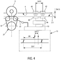
- the figure 4 which does not form part of the invention, schematically illustrates communication means 41-44 of the train 2 with its system infrastructure 10-13.
- the upper part of the figure 4 represents the position of these means of communication relative to the train.
- the lower part of the figure 4 is a detailed view of these means of communication.
- the train communicates via transmitting / receiving antennas 41, 42 which are specific to it, located in the lower part of the train 4, and communicating by induced current with current loops disposed in the channels normally used in operation.
- the bench 1 comprises bench antennas 43, 44 designed to simulate the loops of the operating channel.
- the bench antennas 43, 44 are installed on the structure 7-7, so that each is in front of a respective antenna 41, 44 of the train 2 tested.
- Each antenna 41, 42 of the train 2 is above a bank antenna 43, 44 at a distance D413 substantially equal to the distance between the antennas and the loops on an operating channel.
- the bench antennas are connected to the control unit 10 by the antenna link 13.
- the antennas 41-44 are used for a so-called FS link, where FS is the acronym for Safety Frequency.
- FS is the acronym for Safety Frequency.
- the loops arranged at regular intervals in the operating channel allow to receive a FS carrier that allows the train to slaved speed on the track.
- a real FS antenna 49 comprises a succession of loops 46 which intersect at a defined interval D47.
- Each cross 47 is called a chevron 47.
- Each loop 46 emits a magnetic field that reverses at each chevron.
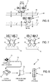
- the figure 6 which does not form part of the invention, illustrates the operation of the link FS on an operating channel.
- the upper part of the figure 6 illustrates a first position of the train 2 with respect to the antenna 19, and, the lower part of the figure 6 illustrates a second position of the train 2 with respect to this antenna.
- the train 2 has two antennas 41, 42 for receiving an FS signal. These antennas 41, 42, respectively known by the names of antenna AREC1 and AREC2, are distant from each other by a fixed distance D412. When these two antennas are above the same loop (upper part of the figure 6 ), they receive a signal in phase. When they are not above the same loop (lower part of the figure 6 ), they receive a signal in opposition of phase. It is this transition that is noted by the train and that allows the detection of rafters.
- the figure 7 which does not form part of the invention, illustrates a simulation of the link FS by the bank 1.
- the left part of the figure 7 illustrates the simulation of a first position of the train 2 in which the FS antennas 41, 42 of the train 2 are above the same loop, and, the right part of the train 2 figure 7 illustrates the simulation of a second position of the train 2 in which the FS antennas 41, 42 of the train 2 are not above the same loop.
- the FS link is simulated by two transmitting antennas 43, 44 located in the bank, each under a respective antenna 41, 42 of the train.
- the transmitting antennas are controlled by the control unit 10 and can generate a signal FS in phase (to the left of the figure 7 ) or in phase opposition (to the right of the figure 7 ).
- the power unit 72, the signal shaping and processing unit and the control computer unit 74 are arranged in the computer rack 11 of the control unit 10.
- a modulation of the FS signal makes it possible to transmit commands to the train.
- This modulation as well as the control of the phase are generated by the unit of shaping and signal processing.
- the link FS ensures the transmission of data for setting the train in motion, in particular the order starting and speed. Special attention is therefore required on the safety aspect of this connection.
- This link must in no case generate a carrier without phase transition while the train is in motion, which would generate a risk of sudden acceleration of the train.
- a speed sensor 51 is installed on one of the belts 27 in order to transmit the speed of rotation.
- the distance D6 represents the distance traveled by the train since the last passage of a chevron.
- the train also has two antennas transmitting anti-collision that cease issuing in some cases related to security. When a lack of emission of these antennas is detected, it causes the stop of the transmission of the signal FS.
- Two antennas receiving collision avoidance signals are placed under the train vis-à-vis anti-collision antennas. These antennas each consist of a housing in which is integrated a coil sized to induce a magnetic coupling for the transmission of information. The received signal is then conditioned and demodulated. The information is transmitted to the control software.
- the train also has telemetry and remote control antennas, called TM / TC antennas.
- a TM / TC link allows exchanges between the train and the control unit.
- the train receives TC signals and responds with TM signals.
- the train has a transmitting antenna TM and receives the TC signals via its AREC antennas 41, 42, provided for the FS signals.
- a signal receiving antenna TM is placed under the train opposite the antenna TM of the train, and a transmitting antenna of the signals TC is placed under the train facing an AREC antenna 41, 42.
- a train / station link called LSV / LVS, allows exchanges between the train and a station.
- the train receives LSV signals and responds with LVS signals.
- the train has an LVS transmit antenna and receives the LSV signals via its AREC antennas 41, 42.
- an antenna receiving signals LVS is placed under the train vis-à-vis the antenna LVS, and an antenna for transmitting signals LSV is placed under the train vis-vis of an AREC antenna.
- the voice exchange When the voice link is established between the station and the train, the voice exchange is operated via a voice antenna located under the train. This antenna operates in transmission and reception.
- a telephone 52 is installed on the desk of the control unit 10 and allows a dialogue with the train.
- the signal transmitted or received by the telephone is conditioned via an electronic resource installed in the bay 11.
- the conditioned signal 14 is then transmitted to an antenna voice installed under the voice antenna of the train.
- the control software of the bank 1 makes it possible to send a TC frame to the train in order to request the establishment of the voice link.
- the control software informs the operator in case of detection of a TM frame transmitted by the train requesting the establishment of the voice link; this information can be reported in a sound and / or visual way.
- Metal studs are generally arranged in the operating channels; they allow a train to know his position on the track and to transmit information.
- An eddy current detector consisting of a bridge of mutual inductances which unbalance in the presence of a metal part to less than 95 mm, is installed in the lower part of the train.
- the pads are metal pieces of varying lengths and spacings installed on the track that are detected by this detector and provide information to the train, including a deceleration instruction or a position information at the dock.
- the figure 9 which is not part of the invention, illustrates a stud simulator 54.
- the simulator 54 comprises a mechanical plate 55 which carries small metal squares 56 that can be electrically isolated or connected.
- relays 57 are used to connect or disconnect the squares. These squares may for example be aluminum or copper.
- the stud detector of the train or not detects the presence of a stud.
- Relays 57 are located near squares 56 that they can isolate or connect electrically and are controlled by a control unit located in bay 11.
- a control unit located in bay 11.
- it connects the set of squares for a duration which is calculated according to the speed of the train. This sequence can be repeated in time to simulate a pair of pads distant from each other by a given distance, so a given time.
- the calculation of the duration of the simulation of a plot is performed by the control software, thanks to the speed sensor 51.
- the train is supplied with electricity by a shoe 61 which is in contact with a feed rail.
- the train 2 is stationary.
- the rail comprises a rail 62.
- the rail 62 comprises a rail section 63 supplied with electricity by a power cable 64.
- the rail further comprises two sections of insulating material 66 disposed on either side of the powered section 63.
- powered section 63 is disposed in the bench 1 so that when the train 2 is in position to be tested, the shoe 61 rests on him.
- the rail further comprises means 67 for driving the powered section 63 in a longitudinal reciprocating motion. This movement allows the wiper not to stick to the rail.
- the powered section 63 further comprises a passive radiator for evacuating the heat due to the friction of the wiper on the rail.
- an electric shaft can be used for the synchronization of all inertial masses, regardless of the distance between them, small or large.
- the bench can also be provided for testing trains comprising a single car or more than two cars. Similarly, it can be provided for a greater or lesser number of axles.
- the inertial mass can be achieved by a foundry process.
- a bench according to the invention is easily adaptable to different types of train. For example, a distance between the rolling units can be easily changed, depending on the distance between the axles of the train to be tested.
Landscapes
- Engineering & Computer Science (AREA)
- Physics & Mathematics (AREA)
- General Physics & Mathematics (AREA)
- Mechanical Engineering (AREA)
- Transportation (AREA)
- Train Traffic Observation, Control, And Security (AREA)
- Electric Propulsion And Braking For Vehicles (AREA)
Claims (4)
- Rolleinheit (8) für einen Prüfstand (1) für einen Zug (2), insbesondere einen automatischen U-Bahnzug, dadurch gekennzeichnet, dass diese umfasst:- zwei Laufbänder (27);- eine Drehwelle (30) mit einer transversalen Achse (X30); und- eine Trägheitsmasse (28), die für einen drehenden Eingriff mit der Welle (30) und um die Achse (X30) montiert ist;wobei jedes Band (27) umfasst:- ein Eingriffsrad (31) vom Typ eines Ritzels, das für einen drehenden Eingriff mit der Welle (30) und um die Achse (X30) montiert ist;- zwei Rollen (33);- ein gezahntes Laufflächenband (32), das über die Rollen gespannt montiert ist und mit dem Antriebsrad (31) kämmt,wobei das Band (32) zwischen den Rollen einen im Wesentlichen horizontalen Abrollbereich (34) bildet und die Bänder (27) derart angeordnet sind, dass auf jedem Abrollbereich (34) ein jeweiliges Rad (6) abrollen kann, das von einem jeweiligen Ende derselben Radachse (5) des Zuges (2) getragen wird, wobei das Abrollen der Räder (6) eine Bewegung der Bänder (27) bewirkt.
- Rolleinheit (8) nach Anspruch 1, dadurch gekennzeichnet, dass die Trägheitsmasse (28) zwischen den Bändern (27) angeordnet ist.
- Rolleinheit (8) nach einem der Ansprüche 1 und 2, dadurch gekennzeichnet, dass diese einen Motor aufweist, vorzugsweise einen Getriebemotor (26), der mit der Trägheitsmasse (28) verbunden ist, wobei der Motor ausgebildet ist zum Anpassen der Trägheit der Trägheitsmasse und/oder zum Simulieren eines Gefälles und/oder zum Kompensieren von inneren Reibungen auf dem Prüfstand.
- Prüfstand (1) für einen Zug (2), insbesondere einen automatischen U-Bahnzug, dadurch gekennzeichnet, dass der Prüfstand mindestens eine Rolleinheit (8) nach einem der vorangehenden Ansprüche aufweist.
Applications Claiming Priority (2)
| Application Number | Priority Date | Filing Date | Title |
|---|---|---|---|
| FR1460213 | 2014-10-23 | ||
| PCT/FR2015/052863 WO2016062980A1 (fr) | 2014-10-23 | 2015-10-23 | Unite de roulement pour un banc dynamique pour tester une rame, notamment une rame de metro automatique, et banc comprennant une telle unite |
Publications (2)
| Publication Number | Publication Date |
|---|---|
| EP3209994A1 EP3209994A1 (de) | 2017-08-30 |
| EP3209994B1 true EP3209994B1 (de) | 2019-11-27 |
Family
ID=54557441
Family Applications (3)
| Application Number | Title | Priority Date | Filing Date |
|---|---|---|---|
| EP15797124.3A Active EP3209994B1 (de) | 2014-10-23 | 2015-10-23 | Walzeneinheit für einen dynamischen prüfstand zum testen eines zuges, insbesondere eines automatischen unterirdischen zuges, und prüfstand mit solch einer einheit |
| EP15797125.0A Active EP3209995B1 (de) | 2014-10-23 | 2015-10-23 | Dynamischer prüfstand zum prüfen eines zugverband, insbesondere eines automatischen u-bahnzugverbands, mit einer elektrischen welle |
| EP15797126.8A Active EP3209531B1 (de) | 2014-10-23 | 2015-10-23 | Vorrichtung zur simulation eines austauschs zwischen einem zug, insbesondere einem automatischen u-bahn-zug, und einem dynamischen, mit solch einer vorrichtung ausgestatteten prüfstand |
Family Applications After (2)
| Application Number | Title | Priority Date | Filing Date |
|---|---|---|---|
| EP15797125.0A Active EP3209995B1 (de) | 2014-10-23 | 2015-10-23 | Dynamischer prüfstand zum prüfen eines zugverband, insbesondere eines automatischen u-bahnzugverbands, mit einer elektrischen welle |
| EP15797126.8A Active EP3209531B1 (de) | 2014-10-23 | 2015-10-23 | Vorrichtung zur simulation eines austauschs zwischen einem zug, insbesondere einem automatischen u-bahn-zug, und einem dynamischen, mit solch einer vorrichtung ausgestatteten prüfstand |
Country Status (7)
| Country | Link |
|---|---|
| US (3) | US10598570B2 (de) |
| EP (3) | EP3209994B1 (de) |
| JP (3) | JP6758305B2 (de) |
| KR (3) | KR20170072317A (de) |
| CN (3) | CN107003211A (de) |
| ES (2) | ES2831452T3 (de) |
| WO (3) | WO2016062983A1 (de) |
Families Citing this family (14)
| Publication number | Priority date | Publication date | Assignee | Title |
|---|---|---|---|---|
| CN107003211A (zh) * | 2014-10-23 | 2017-08-01 | 斯菲瑞测试服务公司 | 用于测试列车尤其是自动地铁列车的动态测试台的滚动单元以及包括该滚动单元的测试台 |
| DE102015007672A1 (de) * | 2015-06-16 | 2016-12-22 | GM Global Technology Operations LLC (n. d. Ges. d. Staates Delaware) | Prüfanordnung zur simulierten Prüfung eines Fahrzeugs auf mindestens einem Prüfstand, Prüfstand mit der Prüfanordnung und Verfahren zur simulierten Prüfung eines Fahrzeugs auf mindestens einem Prüfstand mit der Prüfanordnung |
| CN107526348A (zh) * | 2017-06-07 | 2017-12-29 | 南京铁道职业技术学院 | 地铁系统的控制器的测试装置和方法 |
| CN107505930A (zh) * | 2017-06-07 | 2017-12-22 | 南京铁道职业技术学院 | 地铁的测试装置和方法 |
| RU2668485C1 (ru) * | 2017-10-10 | 2018-10-01 | Федеральное государственное бюджетное образовательное учреждение высшего образования Иркутский государственный университет путей сообщения (ФГБОУ ВО ИрГУПС) | Катковый стенд для оценки динамических параметров тележки вагона |
| US10871421B2 (en) * | 2017-10-19 | 2020-12-22 | Siemens Mobility, Inc. | Locomotive electronic control system testing device and method |
| WO2020209996A1 (en) * | 2019-04-09 | 2020-10-15 | Commscope Technologies Llc | Radio environment monitoring in a base station using a mobile chip |
| FR3096635B1 (fr) * | 2019-06-03 | 2021-06-18 | Safran Landing Systems | Détection de l’état d’un organe de freinage de parc |
| CN112082779B (zh) * | 2019-06-12 | 2022-09-30 | 中南大学 | 地震作用下高速铁路列车走行实时模拟试验系统 |
| CN112393929B (zh) * | 2020-11-17 | 2023-04-28 | 卡斯柯信号有限公司 | 列车静动态测试控制系统及控制方法 |
| US20220268651A1 (en) * | 2021-02-22 | 2022-08-25 | Diversified Products, LLC | Dynamometer For Use With Rail Equipment, And Systems And Methods Of Using Same |
| CN114261383B (zh) * | 2021-12-16 | 2022-10-14 | 中车株洲电力机车有限公司 | 一种齿轨列车带式制动装置间隙指示方法 |
| CN114802352A (zh) * | 2022-03-23 | 2022-07-29 | 张桐 | 一种铁路货车制动装置及其使用方法 |
| DE102023202189A1 (de) * | 2023-03-10 | 2024-09-12 | Siemens Mobility GmbH | Verfahren und System zur Ermittlung von Fahrparametern eines Schienenfahrzeugs |
Family Cites Families (56)
| Publication number | Priority date | Publication date | Assignee | Title |
|---|---|---|---|---|
| US265440A (en) * | 1882-10-03 | Maxim j | ||
| US1950607A (en) * | 1924-10-25 | 1934-03-13 | Bendix Cowdrey Brake Tester In | Testing apparatus |
| GB265440A (en) * | 1926-05-26 | 1927-02-10 | Renault Louis | Apparatus for testing motor vehicles |
| US1894935A (en) * | 1927-01-06 | 1933-01-17 | Bendixcowdrey Brake Tester Inc | Hrake testing equipment |
| US2696104A (en) * | 1951-05-26 | 1954-12-07 | Fairchild Engine & Airplane | Landing gear testing apparatus |
| AT368221B (de) * | 1980-02-27 | 1982-09-27 | Plasser Bahnbaumasch Franz | Schienenkopfoberflaechen-messeinrichtung |
| JPS5718561A (en) * | 1980-07-08 | 1982-01-30 | Mitsubishi Electric Corp | Wayside signal generating equivalent testing system in track type railway |
| US4455866A (en) * | 1982-09-22 | 1984-06-26 | Barrigar Robert H | Motor vehicle testing apparatus |
| JPS59135380A (ja) * | 1983-01-25 | 1984-08-03 | Sumitomo Electric Ind Ltd | 移動体位置制御システムの検査装置 |
| IT1195153B (it) * | 1986-09-05 | 1988-10-12 | Fiat Ferroviaria Savigliano | Apparecchiatura atta ad effettuare spostamenti di veicoli mobili su rotaie e misure sui veicoli stessi |
| NL8700401A (nl) * | 1987-02-17 | 1988-09-16 | Sun Electric Systems Bv | Werkwijze en inrichting voor het beproeven van een antiblokkeersysteem (abs) van een motorvoertuig. |
| US4848142A (en) * | 1987-10-15 | 1989-07-18 | Nissan Motor Sales Co., Ltd. | Motor vehicle performance test apparatus |
| ATE66740T1 (de) | 1988-04-22 | 1991-09-15 | Schenck Ag Carl | Verfahren und vorrichtung zur fuehrung und zum antrieb eines von kraeften beaufschlagten bandantriebs. |
| US5241854A (en) | 1989-01-24 | 1993-09-07 | Kabushiki Kaisha Meidensha | Testing apparatus for bench testing vehicular driving performance |
| JP2874170B2 (ja) * | 1989-01-24 | 1999-03-24 | 株式会社明電舎 | シャシーダイナモメータ |
| JP2594076Y2 (ja) | 1990-02-06 | 1999-04-19 | 株式会社明電舎 | フラットシャシーダイナモメータ |
| US5154076A (en) * | 1991-02-08 | 1992-10-13 | Clayton Industries | Dynamometer for simulating the inertial and road load forces encountered by motor vehicles |
| US5101660A (en) * | 1991-04-05 | 1992-04-07 | Clayton Industries | Method and apparatus for enabling two or four wheel drive vehicles to be tested under simulated road conditions |
| US5269179A (en) * | 1991-11-18 | 1993-12-14 | Frank L. Wells Company | Vehicle testing apparatus |
| JPH06201527A (ja) * | 1993-01-07 | 1994-07-19 | Meidensha Corp | シャシーダイナモメータ |
| US5447060A (en) * | 1993-11-26 | 1995-09-05 | Schenck Pegasus Corporation | Chasis dynamometer with improved torque measurement |
| JP3428208B2 (ja) * | 1994-02-16 | 2003-07-22 | 株式会社明電舎 | 鉄道車両用試験装置 |
| DE19505533A1 (de) * | 1995-02-18 | 1996-08-22 | Teves Gmbh Alfred | Prüfeinheit mit verbesserter Simulationsgüte zur realitätsnahen Prüfung der Fahrdynamik von Kraftfahrzeugen |
| JP3409564B2 (ja) * | 1996-02-28 | 2003-05-26 | 株式会社明電舎 | シャシーダイナモメータ |
| US5844145A (en) * | 1996-03-01 | 1998-12-01 | Snap-On Technologies, Inc. | Chassis dynamometer employing laterally moving roller assemblies during alignment of vehicle |
| US6257054B1 (en) * | 1997-05-21 | 2001-07-10 | Her Majesty The Queen In Right Of Canada, As Represented By The Minister Of Natural Resources | Portable roller dynamometer and vehicle testing method |
| JPH1137904A (ja) * | 1997-07-24 | 1999-02-12 | Hitachi Ltd | 車両の試験装置及び試験方法 |
| JP2000174531A (ja) * | 1998-12-01 | 2000-06-23 | Nippon Signal Co Ltd:The | アンテナ装置及び自動列車制御装置 |
| JP3064498U (ja) * | 1999-06-02 | 2000-01-21 | 三菱電機エンジニアリング株式会社 | 自動列車装置の応動試験装置 |
| US6227625B1 (en) * | 1999-08-24 | 2001-05-08 | Westinghouse Air Brake Company | Two way field tester for EOT device |
| US7188341B1 (en) * | 1999-09-24 | 2007-03-06 | New York Air Brake Corporation | Method of transferring files and analysis of train operational data |
| CN2492846Y (zh) * | 2001-09-03 | 2002-05-22 | 北京铁道工程机电技术研究所 | 铁道机车整车试验装置 |
| US20070271078A1 (en) * | 2002-06-25 | 2007-11-22 | New York Air Brake Corporation | Remote Control Locomotive Simulator |
| US7143017B2 (en) * | 2002-06-25 | 2006-11-28 | New York Air Brake Corporation | Remote control locomotive simulator |
| US7213789B1 (en) * | 2003-04-29 | 2007-05-08 | Eugene Matzan | System for detection of defects in railroad car wheels |
| JP4179277B2 (ja) * | 2004-12-27 | 2008-11-12 | 株式会社日立プラントテクノロジー | 鉄道車両の振動試験方法及び振動試験装置 |
| US20060257826A1 (en) * | 2005-05-11 | 2006-11-16 | Progress Rail Services Corp. | System, method, and apparatus for training railroad personnel in rail vehicle safety and maintenance |
| US8655540B2 (en) * | 2007-08-20 | 2014-02-18 | International Electronic Machines Corp. | Rail vehicle identification and processing |
| WO2009073697A2 (en) * | 2007-12-04 | 2009-06-11 | Techlusion Corporation | Dynamometer |
| JP5387140B2 (ja) * | 2009-05-26 | 2014-01-15 | 株式会社明電舎 | 回転体の角度位置/速度検出装置および動力試験システム |
| KR20110082401A (ko) * | 2010-01-11 | 2011-07-19 | 김봉택 | 열차의 자동 및 일상 검사장치 |
| CN202075135U (zh) * | 2011-03-28 | 2011-12-14 | 辛亮 | 汽车制动检验台的改进 |
| US8596125B2 (en) * | 2011-06-23 | 2013-12-03 | Amsted Rail Company, Inc. | Railway wheel ultrasonic testing apparatus |
| US8596126B2 (en) * | 2011-07-19 | 2013-12-03 | Amsted Rail Company, Inc. | Method and apparatus for a railway wheel ultrasonic testing apparatus |
| CN202305185U (zh) * | 2011-08-29 | 2012-07-04 | 北京新联铁科技发展有限公司 | 轨道车辆转向架动载试验台制动试验装置 |
| ES2398798B1 (es) | 2012-09-17 | 2013-12-03 | Danobat Railway Systems, S. Coop. | Instalación de ensayos dinámicos para testear cojinetes de bogies de vehículos ferroviarios |
| CN102890451B (zh) * | 2012-09-29 | 2014-11-05 | 浙江大学 | 用于车载控制器测试的半实物仿真平台 |
| FR3000798B1 (fr) | 2013-01-10 | 2015-04-17 | Ntn Snr Roulements | Systeme de diagnostic de l'etat structurel d'une unite de roulement d'un engin a roues. |
| CN103217301B (zh) * | 2013-04-11 | 2016-08-03 | 奇瑞汽车股份有限公司 | 一种汽车制动性能检测的装置和方法 |
| CN203698308U (zh) * | 2014-02-17 | 2014-07-09 | 陈昭颖 | 列车进站无线预警系统 |
| DE102014106086A1 (de) * | 2014-04-30 | 2015-11-05 | Knorr-Bremse Systeme für Schienenfahrzeuge GmbH | Rollenprüfstand und Betriebsverfahren für einen Rollenprüfstand |
| CN104071143B (zh) * | 2014-07-10 | 2016-03-16 | 南京浦镇海泰制动设备有限公司 | 一种轨道车辆制动控制单元 |
| CN107003211A (zh) * | 2014-10-23 | 2017-08-01 | 斯菲瑞测试服务公司 | 用于测试列车尤其是自动地铁列车的动态测试台的滚动单元以及包括该滚动单元的测试台 |
| DE102014226910A1 (de) * | 2014-12-23 | 2016-06-23 | Siemens Aktiengesellschaft | Verfahren und Vorrichtung zur Ausführung eines Testvorgangs betreffend ein Schienenfahrzeug |
| JP6471651B2 (ja) * | 2015-08-27 | 2019-02-20 | 株式会社ダイフク | 物品搬送設備 |
| US10029714B2 (en) * | 2016-04-22 | 2018-07-24 | Progress Rail Locomotive Inc. | Locomotive health-based train pacing system |
-
2015
- 2015-10-23 CN CN201580064446.3A patent/CN107003211A/zh active Pending
- 2015-10-23 KR KR1020177014014A patent/KR20170072317A/ko not_active Ceased
- 2015-10-23 WO PCT/FR2015/052867 patent/WO2016062983A1/fr not_active Ceased
- 2015-10-23 EP EP15797124.3A patent/EP3209994B1/de active Active
- 2015-10-23 CN CN201580064440.6A patent/CN107003210B/zh active Active
- 2015-10-23 CN CN201580064439.3A patent/CN107003209B/zh active Active
- 2015-10-23 KR KR1020177014011A patent/KR102611352B1/ko active Active
- 2015-10-23 ES ES15797125T patent/ES2831452T3/es active Active
- 2015-10-23 JP JP2017541171A patent/JP6758305B2/ja active Active
- 2015-10-23 US US15/520,329 patent/US10598570B2/en active Active
- 2015-10-23 WO PCT/FR2015/052865 patent/WO2016062981A1/fr not_active Ceased
- 2015-10-23 EP EP15797125.0A patent/EP3209995B1/de active Active
- 2015-10-23 ES ES15797124T patent/ES2774435T3/es active Active
- 2015-10-23 EP EP15797126.8A patent/EP3209531B1/de active Active
- 2015-10-23 JP JP2017541169A patent/JP6778687B2/ja active Active
- 2015-10-23 US US15/521,020 patent/US10684197B2/en active Active
- 2015-10-23 JP JP2017541170A patent/JP6955444B2/ja active Active
- 2015-10-23 WO PCT/FR2015/052863 patent/WO2016062980A1/fr not_active Ceased
- 2015-10-23 KR KR1020177014016A patent/KR102502564B1/ko active Active
- 2015-10-23 US US15/520,886 patent/US10697859B2/en active Active
Non-Patent Citations (1)
| Title |
|---|
| None * |
Also Published As
| Publication number | Publication date |
|---|---|
| EP3209995B1 (de) | 2020-08-19 |
| JP6778687B2 (ja) | 2020-11-04 |
| EP3209994A1 (de) | 2017-08-30 |
| CN107003209A (zh) | 2017-08-01 |
| EP3209531B1 (de) | 2018-08-29 |
| JP6955444B2 (ja) | 2021-10-27 |
| KR20170072317A (ko) | 2017-06-26 |
| US10697859B2 (en) | 2020-06-30 |
| EP3209531A1 (de) | 2017-08-30 |
| JP6758305B2 (ja) | 2020-09-23 |
| ES2774435T3 (es) | 2020-07-21 |
| US20170336291A1 (en) | 2017-11-23 |
| US20170315023A1 (en) | 2017-11-02 |
| CN107003210B (zh) | 2020-03-06 |
| WO2016062983A1 (fr) | 2016-04-28 |
| KR102611352B1 (ko) | 2023-12-08 |
| KR102502564B1 (ko) | 2023-02-22 |
| EP3209995A1 (de) | 2017-08-30 |
| KR20170072316A (ko) | 2017-06-26 |
| CN107003210A (zh) | 2017-08-01 |
| CN107003211A (zh) | 2017-08-01 |
| US10598570B2 (en) | 2020-03-24 |
| WO2016062981A1 (fr) | 2016-04-28 |
| JP2018504086A (ja) | 2018-02-08 |
| ES2831452T3 (es) | 2021-06-08 |
| JP2017538950A (ja) | 2017-12-28 |
| KR20170072318A (ko) | 2017-06-26 |
| US10684197B2 (en) | 2020-06-16 |
| WO2016062980A1 (fr) | 2016-04-28 |
| JP2017538949A (ja) | 2017-12-28 |
| US20170336292A1 (en) | 2017-11-23 |
| CN107003209B (zh) | 2020-09-01 |
Similar Documents
| Publication | Publication Date | Title |
|---|---|---|
| EP3209994B1 (de) | Walzeneinheit für einen dynamischen prüfstand zum testen eines zuges, insbesondere eines automatischen unterirdischen zuges, und prüfstand mit solch einer einheit | |
| EP1714130B8 (de) | Beweglicher reifenprüfstand und umsetzungsverfahren dafür | |
| CA2960233C (fr) | Vehicule ferroviaire et installation de funiculaire | |
| EP2990292A1 (de) | Anlage und verfahren zum transport über seilbahn | |
| KR101352464B1 (ko) | 급가속 및 급감속이 가능한 모형선 예인전차용 차륜현가장치 | |
| WO2020148408A1 (fr) | Système automatisé de transport de marchandises | |
| FR3084320A1 (fr) | Wagon de mesure de caracteristiques d'une plateforme et d'un armement d'une voie ferree | |
| EP2682321A1 (de) | Diagnosesystem des Strukturzustands von Rollvorrichtungen eines Geräts, einschließlich integrierter Berechnungs- und Analysemittel, die strukturell vom Gerät getrennt sind | |
| JP3382703B2 (ja) | 架空線走行装置 | |
| FR2799162A1 (fr) | Systeme d'entrainement electrique d'un essieu de vehicule automoteur | |
| EP3934959B1 (de) | Kabelfahrzeug-transportanlage und verfahren zum messen einer information bezüglich einer solchen anlage | |
| WO2017093658A1 (fr) | Système de transport guide automatique comportant une plateforme universelle | |
| EP2767818A1 (de) | Diagnosesystem des strukturellen Zustands einer Rolleinheit eines Rollwagens auf einer Schiene, das punktuelle Sende- und Empfangsantennen umfasst |
Legal Events
| Date | Code | Title | Description |
|---|---|---|---|
| STAA | Information on the status of an ep patent application or granted ep patent |
Free format text: STATUS: THE INTERNATIONAL PUBLICATION HAS BEEN MADE |
|
| PUAI | Public reference made under article 153(3) epc to a published international application that has entered the european phase |
Free format text: ORIGINAL CODE: 0009012 |
|
| STAA | Information on the status of an ep patent application or granted ep patent |
Free format text: STATUS: REQUEST FOR EXAMINATION WAS MADE |
|
| 17P | Request for examination filed |
Effective date: 20170418 |
|
| AK | Designated contracting states |
Kind code of ref document: A1 Designated state(s): AL AT BE BG CH CY CZ DE DK EE ES FI FR GB GR HR HU IE IS IT LI LT LU LV MC MK MT NL NO PL PT RO RS SE SI SK SM TR |
|
| AX | Request for extension of the european patent |
Extension state: BA ME |
|
| DAV | Request for validation of the european patent (deleted) | ||
| DAX | Request for extension of the european patent (deleted) | ||
| GRAP | Despatch of communication of intention to grant a patent |
Free format text: ORIGINAL CODE: EPIDOSNIGR1 |
|
| STAA | Information on the status of an ep patent application or granted ep patent |
Free format text: STATUS: GRANT OF PATENT IS INTENDED |
|
| INTG | Intention to grant announced |
Effective date: 20190626 |
|
| GRAS | Grant fee paid |
Free format text: ORIGINAL CODE: EPIDOSNIGR3 |
|
| GRAA | (expected) grant |
Free format text: ORIGINAL CODE: 0009210 |
|
| STAA | Information on the status of an ep patent application or granted ep patent |
Free format text: STATUS: THE PATENT HAS BEEN GRANTED |
|
| AK | Designated contracting states |
Kind code of ref document: B1 Designated state(s): AL AT BE BG CH CY CZ DE DK EE ES FI FR GB GR HR HU IE IS IT LI LT LU LV MC MK MT NL NO PL PT RO RS SE SI SK SM TR |
|
| REG | Reference to a national code |
Ref country code: GB Ref legal event code: FG4D Free format text: NOT ENGLISH |
|
| REG | Reference to a national code |
Ref country code: CH Ref legal event code: EP |
|
| REG | Reference to a national code |
Ref country code: AT Ref legal event code: REF Ref document number: 1207239 Country of ref document: AT Kind code of ref document: T Effective date: 20191215 |
|
| REG | Reference to a national code |
Ref country code: DE Ref legal event code: R096 Ref document number: 602015042605 Country of ref document: DE |
|
| REG | Reference to a national code |
Ref country code: IE Ref legal event code: FG4D Free format text: LANGUAGE OF EP DOCUMENT: FRENCH |
|
| REG | Reference to a national code |
Ref country code: NL Ref legal event code: MP Effective date: 20191127 |
|
| REG | Reference to a national code |
Ref country code: LT Ref legal event code: MG4D |
|
| PG25 | Lapsed in a contracting state [announced via postgrant information from national office to epo] |
Ref country code: FI Free format text: LAPSE BECAUSE OF FAILURE TO SUBMIT A TRANSLATION OF THE DESCRIPTION OR TO PAY THE FEE WITHIN THE PRESCRIBED TIME-LIMIT Effective date: 20191127 Ref country code: BG Free format text: LAPSE BECAUSE OF FAILURE TO SUBMIT A TRANSLATION OF THE DESCRIPTION OR TO PAY THE FEE WITHIN THE PRESCRIBED TIME-LIMIT Effective date: 20200227 Ref country code: LV Free format text: LAPSE BECAUSE OF FAILURE TO SUBMIT A TRANSLATION OF THE DESCRIPTION OR TO PAY THE FEE WITHIN THE PRESCRIBED TIME-LIMIT Effective date: 20191127 Ref country code: SE Free format text: LAPSE BECAUSE OF FAILURE TO SUBMIT A TRANSLATION OF THE DESCRIPTION OR TO PAY THE FEE WITHIN THE PRESCRIBED TIME-LIMIT Effective date: 20191127 Ref country code: NL Free format text: LAPSE BECAUSE OF FAILURE TO SUBMIT A TRANSLATION OF THE DESCRIPTION OR TO PAY THE FEE WITHIN THE PRESCRIBED TIME-LIMIT Effective date: 20191127 Ref country code: LT Free format text: LAPSE BECAUSE OF FAILURE TO SUBMIT A TRANSLATION OF THE DESCRIPTION OR TO PAY THE FEE WITHIN THE PRESCRIBED TIME-LIMIT Effective date: 20191127 Ref country code: NO Free format text: LAPSE BECAUSE OF FAILURE TO SUBMIT A TRANSLATION OF THE DESCRIPTION OR TO PAY THE FEE WITHIN THE PRESCRIBED TIME-LIMIT Effective date: 20200227 Ref country code: GR Free format text: LAPSE BECAUSE OF FAILURE TO SUBMIT A TRANSLATION OF THE DESCRIPTION OR TO PAY THE FEE WITHIN THE PRESCRIBED TIME-LIMIT Effective date: 20200228 |
|
| PG25 | Lapsed in a contracting state [announced via postgrant information from national office to epo] |
Ref country code: HR Free format text: LAPSE BECAUSE OF FAILURE TO SUBMIT A TRANSLATION OF THE DESCRIPTION OR TO PAY THE FEE WITHIN THE PRESCRIBED TIME-LIMIT Effective date: 20191127 Ref country code: IS Free format text: LAPSE BECAUSE OF FAILURE TO SUBMIT A TRANSLATION OF THE DESCRIPTION OR TO PAY THE FEE WITHIN THE PRESCRIBED TIME-LIMIT Effective date: 20200327 Ref country code: RS Free format text: LAPSE BECAUSE OF FAILURE TO SUBMIT A TRANSLATION OF THE DESCRIPTION OR TO PAY THE FEE WITHIN THE PRESCRIBED TIME-LIMIT Effective date: 20191127 |
|
| PG25 | Lapsed in a contracting state [announced via postgrant information from national office to epo] |
Ref country code: AL Free format text: LAPSE BECAUSE OF FAILURE TO SUBMIT A TRANSLATION OF THE DESCRIPTION OR TO PAY THE FEE WITHIN THE PRESCRIBED TIME-LIMIT Effective date: 20191127 |
|
| REG | Reference to a national code |
Ref country code: ES Ref legal event code: FG2A Ref document number: 2774435 Country of ref document: ES Kind code of ref document: T3 Effective date: 20200721 |
|
| PG25 | Lapsed in a contracting state [announced via postgrant information from national office to epo] |
Ref country code: CZ Free format text: LAPSE BECAUSE OF FAILURE TO SUBMIT A TRANSLATION OF THE DESCRIPTION OR TO PAY THE FEE WITHIN THE PRESCRIBED TIME-LIMIT Effective date: 20191127 Ref country code: RO Free format text: LAPSE BECAUSE OF FAILURE TO SUBMIT A TRANSLATION OF THE DESCRIPTION OR TO PAY THE FEE WITHIN THE PRESCRIBED TIME-LIMIT Effective date: 20191127 Ref country code: EE Free format text: LAPSE BECAUSE OF FAILURE TO SUBMIT A TRANSLATION OF THE DESCRIPTION OR TO PAY THE FEE WITHIN THE PRESCRIBED TIME-LIMIT Effective date: 20191127 Ref country code: PT Free format text: LAPSE BECAUSE OF FAILURE TO SUBMIT A TRANSLATION OF THE DESCRIPTION OR TO PAY THE FEE WITHIN THE PRESCRIBED TIME-LIMIT Effective date: 20200419 Ref country code: DK Free format text: LAPSE BECAUSE OF FAILURE TO SUBMIT A TRANSLATION OF THE DESCRIPTION OR TO PAY THE FEE WITHIN THE PRESCRIBED TIME-LIMIT Effective date: 20191127 |
|
| REG | Reference to a national code |
Ref country code: DE Ref legal event code: R097 Ref document number: 602015042605 Country of ref document: DE |
|
| PG25 | Lapsed in a contracting state [announced via postgrant information from national office to epo] |
Ref country code: SM Free format text: LAPSE BECAUSE OF FAILURE TO SUBMIT A TRANSLATION OF THE DESCRIPTION OR TO PAY THE FEE WITHIN THE PRESCRIBED TIME-LIMIT Effective date: 20191127 Ref country code: SK Free format text: LAPSE BECAUSE OF FAILURE TO SUBMIT A TRANSLATION OF THE DESCRIPTION OR TO PAY THE FEE WITHIN THE PRESCRIBED TIME-LIMIT Effective date: 20191127 |
|
| PLBE | No opposition filed within time limit |
Free format text: ORIGINAL CODE: 0009261 |
|
| STAA | Information on the status of an ep patent application or granted ep patent |
Free format text: STATUS: NO OPPOSITION FILED WITHIN TIME LIMIT |
|
| 26N | No opposition filed |
Effective date: 20200828 |
|
| PG25 | Lapsed in a contracting state [announced via postgrant information from national office to epo] |
Ref country code: PL Free format text: LAPSE BECAUSE OF FAILURE TO SUBMIT A TRANSLATION OF THE DESCRIPTION OR TO PAY THE FEE WITHIN THE PRESCRIBED TIME-LIMIT Effective date: 20191127 Ref country code: SI Free format text: LAPSE BECAUSE OF FAILURE TO SUBMIT A TRANSLATION OF THE DESCRIPTION OR TO PAY THE FEE WITHIN THE PRESCRIBED TIME-LIMIT Effective date: 20191127 |
|
| REG | Reference to a national code |
Ref country code: CH Ref legal event code: PL |
|
| PG25 | Lapsed in a contracting state [announced via postgrant information from national office to epo] |
Ref country code: MC Free format text: LAPSE BECAUSE OF FAILURE TO SUBMIT A TRANSLATION OF THE DESCRIPTION OR TO PAY THE FEE WITHIN THE PRESCRIBED TIME-LIMIT Effective date: 20191127 Ref country code: LU Free format text: LAPSE BECAUSE OF NON-PAYMENT OF DUE FEES Effective date: 20201023 |
|
| PG25 | Lapsed in a contracting state [announced via postgrant information from national office to epo] |
Ref country code: CH Free format text: LAPSE BECAUSE OF NON-PAYMENT OF DUE FEES Effective date: 20201031 Ref country code: LI Free format text: LAPSE BECAUSE OF NON-PAYMENT OF DUE FEES Effective date: 20201031 |
|
| PG25 | Lapsed in a contracting state [announced via postgrant information from national office to epo] |
Ref country code: IE Free format text: LAPSE BECAUSE OF NON-PAYMENT OF DUE FEES Effective date: 20201023 |
|
| PG25 | Lapsed in a contracting state [announced via postgrant information from national office to epo] |
Ref country code: TR Free format text: LAPSE BECAUSE OF FAILURE TO SUBMIT A TRANSLATION OF THE DESCRIPTION OR TO PAY THE FEE WITHIN THE PRESCRIBED TIME-LIMIT Effective date: 20191127 Ref country code: MT Free format text: LAPSE BECAUSE OF FAILURE TO SUBMIT A TRANSLATION OF THE DESCRIPTION OR TO PAY THE FEE WITHIN THE PRESCRIBED TIME-LIMIT Effective date: 20191127 Ref country code: CY Free format text: LAPSE BECAUSE OF FAILURE TO SUBMIT A TRANSLATION OF THE DESCRIPTION OR TO PAY THE FEE WITHIN THE PRESCRIBED TIME-LIMIT Effective date: 20191127 |
|
| PG25 | Lapsed in a contracting state [announced via postgrant information from national office to epo] |
Ref country code: MK Free format text: LAPSE BECAUSE OF FAILURE TO SUBMIT A TRANSLATION OF THE DESCRIPTION OR TO PAY THE FEE WITHIN THE PRESCRIBED TIME-LIMIT Effective date: 20191127 |
|
| PGFP | Annual fee paid to national office [announced via postgrant information from national office to epo] |
Ref country code: DE Payment date: 20251029 Year of fee payment: 11 |
|
| PGFP | Annual fee paid to national office [announced via postgrant information from national office to epo] |
Ref country code: GB Payment date: 20251028 Year of fee payment: 11 |
|
| PGFP | Annual fee paid to national office [announced via postgrant information from national office to epo] |
Ref country code: AT Payment date: 20251029 Year of fee payment: 11 |
|
| PGFP | Annual fee paid to national office [announced via postgrant information from national office to epo] |
Ref country code: IT Payment date: 20251029 Year of fee payment: 11 |
|
| PGFP | Annual fee paid to national office [announced via postgrant information from national office to epo] |
Ref country code: FR Payment date: 20251028 Year of fee payment: 11 |
|
| PGFP | Annual fee paid to national office [announced via postgrant information from national office to epo] |
Ref country code: BE Payment date: 20251029 Year of fee payment: 11 |
|
| PGFP | Annual fee paid to national office [announced via postgrant information from national office to epo] |
Ref country code: ES Payment date: 20251103 Year of fee payment: 11 |