EP3210076B1 - Méthode de pilotage pour un afficheur électrophorétique polychrome - Google Patents
Méthode de pilotage pour un afficheur électrophorétique polychrome Download PDFInfo
- Publication number
- EP3210076B1 EP3210076B1 EP15751411.8A EP15751411A EP3210076B1 EP 3210076 B1 EP3210076 B1 EP 3210076B1 EP 15751411 A EP15751411 A EP 15751411A EP 3210076 B1 EP3210076 B1 EP 3210076B1
- Authority
- EP
- European Patent Office
- Prior art keywords
- particles
- type
- driving voltage
- viewing side
- color
- Prior art date
- Legal status (The legal status is an assumption and is not a legal conclusion. Google has not performed a legal analysis and makes no representation as to the accuracy of the status listed.)
- Active
Links
Images


Classifications
-
- G—PHYSICS
- G02—OPTICS
- G02F—OPTICAL DEVICES OR ARRANGEMENTS FOR THE CONTROL OF LIGHT BY MODIFICATION OF THE OPTICAL PROPERTIES OF THE MEDIA OF THE ELEMENTS INVOLVED THEREIN; NON-LINEAR OPTICS; FREQUENCY-CHANGING OF LIGHT; OPTICAL LOGIC ELEMENTS; OPTICAL ANALOGUE/DIGITAL CONVERTERS
- G02F1/00—Devices or arrangements for the control of the intensity, colour, phase, polarisation or direction of light arriving from an independent light source, e.g. switching, gating or modulating; Non-linear optics
- G02F1/01—Devices or arrangements for the control of the intensity, colour, phase, polarisation or direction of light arriving from an independent light source, e.g. switching, gating or modulating; Non-linear optics for the control of the intensity, phase, polarisation or colour
- G02F1/165—Devices or arrangements for the control of the intensity, colour, phase, polarisation or direction of light arriving from an independent light source, e.g. switching, gating or modulating; Non-linear optics for the control of the intensity, phase, polarisation or colour based on translational movement of particles in a fluid under the influence of an applied field
- G02F1/166—Devices or arrangements for the control of the intensity, colour, phase, polarisation or direction of light arriving from an independent light source, e.g. switching, gating or modulating; Non-linear optics for the control of the intensity, phase, polarisation or colour based on translational movement of particles in a fluid under the influence of an applied field characterised by the electro-optical or magneto-optical effect
- G02F1/167—Devices or arrangements for the control of the intensity, colour, phase, polarisation or direction of light arriving from an independent light source, e.g. switching, gating or modulating; Non-linear optics for the control of the intensity, phase, polarisation or colour based on translational movement of particles in a fluid under the influence of an applied field characterised by the electro-optical or magneto-optical effect by electrophoresis
-
- G—PHYSICS
- G02—OPTICS
- G02F—OPTICAL DEVICES OR ARRANGEMENTS FOR THE CONTROL OF LIGHT BY MODIFICATION OF THE OPTICAL PROPERTIES OF THE MEDIA OF THE ELEMENTS INVOLVED THEREIN; NON-LINEAR OPTICS; FREQUENCY-CHANGING OF LIGHT; OPTICAL LOGIC ELEMENTS; OPTICAL ANALOGUE/DIGITAL CONVERTERS
- G02F1/00—Devices or arrangements for the control of the intensity, colour, phase, polarisation or direction of light arriving from an independent light source, e.g. switching, gating or modulating; Non-linear optics
- G02F1/01—Devices or arrangements for the control of the intensity, colour, phase, polarisation or direction of light arriving from an independent light source, e.g. switching, gating or modulating; Non-linear optics for the control of the intensity, phase, polarisation or colour
- G02F1/13—Devices or arrangements for the control of the intensity, colour, phase, polarisation or direction of light arriving from an independent light source, e.g. switching, gating or modulating; Non-linear optics for the control of the intensity, phase, polarisation or colour based on liquid crystals, e.g. single liquid crystal display cells
- G02F1/133—Constructional arrangements; Operation of liquid crystal cells; Circuit arrangements
- G02F1/13306—Circuit arrangements or driving methods for the control of single liquid crystal cells
-
- G—PHYSICS
- G02—OPTICS
- G02F—OPTICAL DEVICES OR ARRANGEMENTS FOR THE CONTROL OF LIGHT BY MODIFICATION OF THE OPTICAL PROPERTIES OF THE MEDIA OF THE ELEMENTS INVOLVED THEREIN; NON-LINEAR OPTICS; FREQUENCY-CHANGING OF LIGHT; OPTICAL LOGIC ELEMENTS; OPTICAL ANALOGUE/DIGITAL CONVERTERS
- G02F1/00—Devices or arrangements for the control of the intensity, colour, phase, polarisation or direction of light arriving from an independent light source, e.g. switching, gating or modulating; Non-linear optics
- G02F1/01—Devices or arrangements for the control of the intensity, colour, phase, polarisation or direction of light arriving from an independent light source, e.g. switching, gating or modulating; Non-linear optics for the control of the intensity, phase, polarisation or colour
- G02F1/165—Devices or arrangements for the control of the intensity, colour, phase, polarisation or direction of light arriving from an independent light source, e.g. switching, gating or modulating; Non-linear optics for the control of the intensity, phase, polarisation or colour based on translational movement of particles in a fluid under the influence of an applied field
- G02F1/1685—Operation of cells; Circuit arrangements affecting the entire cell
-
- G—PHYSICS
- G09—EDUCATION; CRYPTOGRAPHY; DISPLAY; ADVERTISING; SEALS
- G09G—ARRANGEMENTS OR CIRCUITS FOR CONTROL OF INDICATING DEVICES USING STATIC MEANS TO PRESENT VARIABLE INFORMATION
- G09G3/00—Control arrangements or circuits, of interest only in connection with visual indicators other than cathode-ray tubes
- G09G3/20—Control arrangements or circuits, of interest only in connection with visual indicators other than cathode-ray tubes for presentation of an assembly of a number of characters, e.g. a page, by composing the assembly by combination of individual elements arranged in a matrix no fixed position being assigned to or needed to be assigned to the individual characters or partial characters
- G09G3/2007—Display of intermediate tones
- G09G3/2011—Display of intermediate tones by amplitude modulation
-
- G—PHYSICS
- G09—EDUCATION; CRYPTOGRAPHY; DISPLAY; ADVERTISING; SEALS
- G09G—ARRANGEMENTS OR CIRCUITS FOR CONTROL OF INDICATING DEVICES USING STATIC MEANS TO PRESENT VARIABLE INFORMATION
- G09G3/00—Control arrangements or circuits, of interest only in connection with visual indicators other than cathode-ray tubes
- G09G3/20—Control arrangements or circuits, of interest only in connection with visual indicators other than cathode-ray tubes for presentation of an assembly of a number of characters, e.g. a page, by composing the assembly by combination of individual elements arranged in a matrix no fixed position being assigned to or needed to be assigned to the individual characters or partial characters
- G09G3/34—Control arrangements or circuits, of interest only in connection with visual indicators other than cathode-ray tubes for presentation of an assembly of a number of characters, e.g. a page, by composing the assembly by combination of individual elements arranged in a matrix no fixed position being assigned to or needed to be assigned to the individual characters or partial characters by control of light from an independent source
- G09G3/3433—Control arrangements or circuits, of interest only in connection with visual indicators other than cathode-ray tubes for presentation of an assembly of a number of characters, e.g. a page, by composing the assembly by combination of individual elements arranged in a matrix no fixed position being assigned to or needed to be assigned to the individual characters or partial characters by control of light from an independent source using light modulating elements actuated by an electric field and being other than liquid crystal devices and electrochromic devices
- G09G3/344—Control arrangements or circuits, of interest only in connection with visual indicators other than cathode-ray tubes for presentation of an assembly of a number of characters, e.g. a page, by composing the assembly by combination of individual elements arranged in a matrix no fixed position being assigned to or needed to be assigned to the individual characters or partial characters by control of light from an independent source using light modulating elements actuated by an electric field and being other than liquid crystal devices and electrochromic devices based on particles moving in a fluid or in a gas, e.g. electrophoretic devices
-
- G—PHYSICS
- G02—OPTICS
- G02F—OPTICAL DEVICES OR ARRANGEMENTS FOR THE CONTROL OF LIGHT BY MODIFICATION OF THE OPTICAL PROPERTIES OF THE MEDIA OF THE ELEMENTS INVOLVED THEREIN; NON-LINEAR OPTICS; FREQUENCY-CHANGING OF LIGHT; OPTICAL LOGIC ELEMENTS; OPTICAL ANALOGUE/DIGITAL CONVERTERS
- G02F1/00—Devices or arrangements for the control of the intensity, colour, phase, polarisation or direction of light arriving from an independent light source, e.g. switching, gating or modulating; Non-linear optics
- G02F1/01—Devices or arrangements for the control of the intensity, colour, phase, polarisation or direction of light arriving from an independent light source, e.g. switching, gating or modulating; Non-linear optics for the control of the intensity, phase, polarisation or colour
- G02F1/165—Devices or arrangements for the control of the intensity, colour, phase, polarisation or direction of light arriving from an independent light source, e.g. switching, gating or modulating; Non-linear optics for the control of the intensity, phase, polarisation or colour based on translational movement of particles in a fluid under the influence of an applied field
- G02F1/1675—Constructional details
- G02F2001/1678—Constructional details characterised by the composition or particle type
-
- G—PHYSICS
- G09—EDUCATION; CRYPTOGRAPHY; DISPLAY; ADVERTISING; SEALS
- G09G—ARRANGEMENTS OR CIRCUITS FOR CONTROL OF INDICATING DEVICES USING STATIC MEANS TO PRESENT VARIABLE INFORMATION
- G09G2300/00—Aspects of the constitution of display devices
- G09G2300/04—Structural and physical details of display devices
- G09G2300/0439—Pixel structures
- G09G2300/0452—Details of colour pixel setup, e.g. pixel composed of a red, a blue and two green components
-
- G—PHYSICS
- G09—EDUCATION; CRYPTOGRAPHY; DISPLAY; ADVERTISING; SEALS
- G09G—ARRANGEMENTS OR CIRCUITS FOR CONTROL OF INDICATING DEVICES USING STATIC MEANS TO PRESENT VARIABLE INFORMATION
- G09G3/00—Control arrangements or circuits, of interest only in connection with visual indicators other than cathode-ray tubes
- G09G3/20—Control arrangements or circuits, of interest only in connection with visual indicators other than cathode-ray tubes for presentation of an assembly of a number of characters, e.g. a page, by composing the assembly by combination of individual elements arranged in a matrix no fixed position being assigned to or needed to be assigned to the individual characters or partial characters
- G09G3/2003—Display of colours
Definitions
- the present invention is directed to a method of driving an electrophoretic color display device in which each pixel can display at least five color states.
- color filters are often used.
- the most common approach is to add color filters on top of black/white sub-pixels of a pixellated display to display the red, green and blue colors.
- red color is desired
- blue color is desired
- red and blue sub-pixels are turned to the black state so that the only color displayed is blue.
- red and blue sub-pixels are turned to the black state so that the only color displayed is green.
- black state is desired, all three-sub-pixels are turned to the black state.
- the white state is desired, the three sub-pixels are turned to red, green and blue, respectively, and as a result, a white state is seen by the viewer.
- each of the sub-pixels has a reflectance of about one third of the desired white state, the white state is fairly dim.
- a fourth sub-pixel may be added which can display only the black and white states, so that the white level is doubled at the expense of the red, green or blue color level (where each sub-pixel is only one fourth of the area of the pixel).
- Brighter colors can be achieved by adding light from the white pixel, but this is achieved at the expense of color gamut to cause the colors to be very light and unsaturated.
- a similar result can be achieved by reducing the color saturation of the three sub-pixels.
- the white level is normally substantially less than half of that of a black and white display, rendering it an unacceptable choice for display devices, such as e-readers or displays that need well readable black-white brightness and contrast.
- JP 2010-044114A describes a color electrophoretic display having either four types of particles (with two positive and two negative particles) or five types of particles (with three particles of one polarity and two of the opposite polarity), each of the types of particles being of a different color.
- the charges on the various type of particles and the dielectric constants or other physical properties of the various types of particles are arranged to that, when a constant voltage is applied driving two or three types of particles towards a viewing side of the display, initially one type of particles moves faster than the other(s), but after the constant voltage has been applied for an extended period, a different type of particle moves faster (see Figure 2 and Paragraphs [0039]-[0045] of this publication).
- US 2012/0154899 A1 discloses an electrophoretic display comprising capsules with first to fifth particles in a fluid, the capsules being sandwiched between first and second substrates with first and second electrodes.
- the first to fifth particles have the same charge polarity and decreasing charge magnitudes.
- the particles are driven using voltages with different polarities and magnitudes.
- US 2010/0020384 A1 describes an electrophoretic display comprising a pair of substrates, a liquid enclosed between the substrates, and first, second and third colored particles dispersed in the liquid.
- the first colored particles have a first color and move in response to an electric field formed between the substrates.
- the second colored particles have a second color and move in an electric field in an opposite direction of the first colored particles.
- the third colored particles have a third color, and a particle diameter such that the third colored particles move through clearances between the first colored particles and the second colored particles in a state in which the first colored particles and the second colored particles have aggregated together, the third colored particles moving in response to an electric field that is formed between the substrates.
- the present invention provides a driving method for driving an electrophoretic display which comprises a first surface on a viewing side, a second surface, and an electrophoretic fluid sandwiched between a common electrode at the viewing side and a layer of pixel electrodes and comprising a first type of particles, a second type of particles, a third type of particles, a fourth type of particles and a fifth type of particles, all of which are dispersed in a solvent or solvent mixture, wherein:
- the method of the invention further comprises:
- the first and second types of particles may be black and white, or vice versa.
- the first and second types of particles may be black and yellow, or vice versa.
- the first type of particles is black
- the second type of particles is white
- the third, fourth and fifth types of particles are red, green and blue, respectively.
- the first type of particles is black
- the second type of particles is yellow
- the third, fourth and fifth types of particles are blue, red and white, respectively.
- the third, fourth and fifth types of particles may be red, yellow and blue, respectively.
- the fluid may further comprise non-charged or slightly charged neutral buoyancy particles.
- each of steps (iii), (iv) and (v) may be effected by applying the (third, fourth or fifth) driving voltage alternating between the driving voltage and no driving voltage.
- Figure 1 depicts a display layer which can display different color states.
- FIGS 2-1 to 2-5 illustrate various colors transitions occurring in one driving method of the present invention.
- Figure 3 demonstrates single driving pulses.
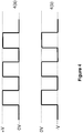
- Figure 4 demonstrates pulsed waveforms.
- Figure 5 demonstrates display cells unaligned with pixel electrodes.
- the electrophoretic fluid used in the driving method of the present invention comprises at least five types of particles dispersed in a dielectric solvent or solvent mixture.
- the particles are herein referred to as a first type of particles, a second type of particles, a third type of particles, a fourth type of particles and a fifth type of particles, as shown in Figure 1 .
- the five types of particles are of different colors.
- the particles may be of any colors as long as the multiple types of particles are visually distinguishable.
- the five types of particles may be any combinations of white particles (W), black particles (K), red particles (R), green particles (G), blue particles (B), cyan particles (C), magenta particles (M) and yellow particles (Y).
- the five different types of particles may have other distinct optical characteristics, such as optical transmission, reflectance, luminescence or, in the case of displays intended for machine reading, pseudo-color in the sense of a change in reflectance of electromagnetic wavelengths outside the visible range.
- the five types of particles have different levels of charge potential.
- the five types of particles may be high-positive particles, mid-positive particles, low-positive particles, high-negative particles and low-negative particles.
- the five types of particles may be high-negative particles, mid-negative particles, low-negative particles, high-positive particles and low-positive particles.
- charge potential in the context of the present application, may be used interchangeably with “zeta potential”.
- the charge polarities and levels of charge potential of the particles may be tuned, according to the method described in US Application Publication No. 2014-0011913 .
- the magnitudes of the "high-positive” particles and the "high-negative” particles may be the same or different.
- the magnitudes of the "low- positive” particles and the "low-negative” particles may be the same or different.
- the charge potentials of the particles may be measured in terms of zeta potential.
- the zeta potential is determined by Colloidal Dynamics AcoustoSizer IIM with a CSPU-100 signal processing unit, ESA EN# Attn flow through cell (K:127).
- the instrument constants such as density of the solvent used in the sample, dielectric constant of the solvent, speed of sound in the solvent, viscosity of the solvent, all of which at the testing temperature (25°C) are entered before testing.
- Pigment samples are dispersed in the solvent (which is usually a hydrocarbon fluid having less than 12 carbon atoms), and diluted to be 5-10% by weight.
- the sample also contains a charge control agent (Solsperse 17000, available from Lubrizol Corporation, a Berkshire Hathaway company; "Solsperse” is a Registered Trade Mark), with a weight ratio of 1:10 of the charge control agent to the particles.
- Solsperse 17000 available from Lubrizol Corporation, a Berkshire Hathaway company; "Solsperse” is a Registered Trade Mark
- the mass of the diluted sample is determined and the sample is then loaded into the flow through cell for determination of the zeta potential.
- the display fluid is sandwiched between two electrode layers.
- One of the electrode layers is a common electrode (11) which is a transparent electrode layer (e.g., ITO), spreading over the entire top of the display device.
- the other electrode layer (12) is a layer of pixel electrodes (12a).
- each pixel has a corresponding pixel electrode (12a).
- the pixel electrodes are described in US Patent No. 7,046,228 . It is noted that while active matrix driving with a thin film transistor (TFT) backplane is mentioned for the layer of pixel electrodes, the scope of the present invention encompasses other types of electrode addressing as long as the electrodes serve the desired functions.
- TFT thin film transistor
- a display device driven by the method of the present invention has two surfaces, a first surface (13) on the viewing side and a second surface (14) on the opposite side from the first surface (13).
- the second surface therefore is on the non-viewing side.
- viewing side refers to the side at which images are viewed.
- the solvent in which the particles are dispersed is clear and colorless. It preferably has a dielectric constant in the range of about 2 to about 30, more preferably about 2 to about 15 for high particle mobility.
- suitable dielectric solvent include hydrocarbons such as isoparaffin, decahydronaphthalene (DECALIN), 5-ethylidene-2-norbornene, fatty oils, paraffin oil, silicon fluids, aromatic hydrocarbons such as toluene, xylene, phenylxylylethane, dodecylbenzene or alkylnaphthalene, halogenated solvents such as perfluorodecalin, perfluorotoluene, perfluoroxylene, dichlorobenzotrifluoride, 3,4,5 - trichlorobenzotrifluoride, chloropentafluoro-benzene, dichlorononane or pentachlorobenzene, and perfluorinated solvents such as FC-43, FC-70 or
- the particles are preferably opaque. They may be primary particles without a polymer shell. Alternatively, each particle may comprise an insoluble core with a polymer shell.
- the core could be either an organic or inorganic pigment, and it may be a single core particle or an aggregate of multiple core particles.
- the particles may also be hollow particles.
- the primary particles or core particles may be TiO 2 , ZrO 2 , ZnO, Al 2 O 3 , Sb 2 O 3 , BaSO 4 , PbSO 4 or the like.
- the primary particles or core particles may be Cl pigment black 26 or 28 or the like (e.g., manganese ferrite black spinel or copper chromite black spinel) or carbon black.
- the primary particles or core particles may include, but are not limited to, CI pigment PR 254, PR122, PR149, PG36, PG58, PG7, PB28, PB15:3, PY83, PY138, PY150, PY155 or PY20.
- CI pigment PR 254, PR122, PR149, PG36, PG58, PG7, PB28, PB15:3, PY83, PY138, PY150, PY155 or PY20 are commonly used organic pigments described in color index handbooks, “ New Pigment Application Technology” (CMC Publishing Co, Ltd, 1986 ) and “ Printing Ink Technology” (CMC Publishing Co, Ltd, 1984 ).
- Clariant Hostaperm Red D3G 70-EDS Hostaperm Pink E-EDS, PV fast red D3G, Hostaperm red D3G 70, Hostaperm Blue B2G-EDS, Hostaperm Yellow H4G-EDS, F2G-EDS, Novoperm Yellow HR-70-EDS, Hostaperm Green GNX, BASF Irgazine red L 3630, Cinquasia Red L 4100 HD, and Irgazin Red L 3660 HD; Sun Chemical phthalocyanine blue, phthalocyanine green, diarylide yellow or diarylide AAOT yellow.
- the primary particles or core particles may also be inorganic pigments, such as red, green, blue and yellow pigments. Examples may include, but are not limited to, CI pigment blue 28, CI pigment green 50 and CI pigment yellow 227.
- the percentages of different types of particles in the fluid may vary. For example, one type of particles may take up 0.1% to 10%, preferably 0.5% to 5%, by volume of the electrophoretic fluid; another type of particles may take up 1% to 50%, preferably 5% to 20%, by volume of the fluid; and each of the remaining types of particles may take up 2% to 20%, preferably 4% to 10%, by volume of the fluid.
- the five types of particles may have different particle sizes.
- the smaller particles may have a size which ranges from about 50 nm to about 800nm.
- the larger particles may have a size which is about 2 to about 50 times, and more preferably about 2 to about 10 times, the sizes of the smaller particles.
- the black particles (K) (i.e., the first type) carry a positive charge and the yellow particles (Y) (i.e., the second type) carry a negative charge.
- the blue (B) i.e., the third type
- red (R) i.e., the fourth type
- the white (W) particles are negatively charged; but their magnitude is less than that of the yellow particles, which means that the yellow particles are high-negative particles and the white particles are low-negative particles.
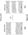
- the low positively charged red and mid positively charged blue particles move slower than the high positively charged black particles and as a result, the blue particles are above the black particles but below the red particles because the blue particles carry higher charge potential than the red particles.
- the black particles are closest to the pixel electrode side.
- the low negatively charged white particles move slower than the high negatively charged yellow particles, and therefore the white particles are below the yellow particles and therefore not seen at the viewing side. In this case, a yellow color is seen at the viewing side (State 2(a) in Figure 2-1 ).
- the high driving voltage applied to cause the transitions shown in Figure 2-1 may be in the form of a single pulse as shown in Figure 3a or 3b or a pulsed waveform as shown in Figure 4a or 4b , in which periods in which the driving voltage is applied alternate with periods in which zero driving voltage is applied.
- the pulsed waveform has alternating 0V and a driving voltage.
- the magnitude of the driving voltage referred to may be or may not be the same as that of the driving voltage for the single pulse method.
- the pulsed waveform may lead to better color performance because it can prevent aggregation of the particles with each other, which usually causes reduction of hiding power of the layers of the particles.
- attraction force in the context of the present application, encompasses electrostatic interactions, linearly dependent on the particle charge potentials, and the attraction force can be further enhanced by introducing other forces, such as Van der Waals forces, hydrophobic interactions or the like.
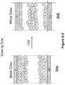
- the electric field generated by the low driving voltage is sufficient to separate the low negatively charged white and low positively charged red particles to cause the red particles to move to the common electrode (21) side (i.e., the viewing side) and the white particles to move to the pixel electrode (22a) side.
- a red color is seen (State 2(c) in Figure 2-2 ).
- the white particles are closest to the pixel electrode.
- the low positive driving voltage used in Figure 2-2 may be applied as a single pulse as shown in Figure 3a or 3b or a pulsed waveform as shown in Figure 4a or 4b .
- the magnitude of the driving voltage in the pulsed waveform may be the same as, or different from, that of the single driving pulse. In the pulsed waveform, there may be 10-200 cycles of pulsing.
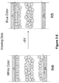
- the electric field generated by the low driving voltage is sufficient to separate the low negatively charged white and the low positively charged red particles to cause the white particles to move to the common electrode side (i.e., the viewing side) and the red particles move to the pixel electrode side.
- the white color is seen (State 2(d) in Figure 2-3 ).
- the red particles, in this case, are closest to the pixel electrode.
- the low negative driving voltage may be applied as a single pulse as shown in Figure 3a or 3b or a pulsed waveform as shown in Figure 4a or 4b .
- the magnitude of the driving voltage in the pulsed waveform may be the same as, or different from, that of the single driving pulse. In the pulsed waveform, there may be 10-200 cycles of pulsing.
- Figure 2-4 shows how a blue color state (which is the color of the second highest positively charged particles) may be achieved from the white state (State 2(d), which is the color of the lower negatively charged particles).
- a medium positive driving voltage (e.g., +12V) is applied to a pixel electrode in the white state (State 2(d) in Figure 2-4 ).
- the voltage applied is not sufficient to separate the high positively charged black from the high negatively charged yellow particles, but sufficient to cause the mid positively charged blue particles to break away from the pack and move towards the viewing side. In this scenario, the high positively charged black particles will not be seen at the viewing side.
- the low negatively charged white particles move away from the viewing side towards the pixel electrode side.
- the electric field generated by the mid positive driving voltage of +12V is sufficient to separate the low negatively charged white particles from the high positively charged black particles.
- the white particles move to the pixel electrode side.
- the low positively charged red particles may be separated from the high negatively charged yellow particles and they move from the pixel electrode side to the common electrode side.
- the blue particles have higher charge potential and move faster than the red particles, a high-quality blue color therefore can be seen at the viewing side.
- This single pulse method with a medium positive driving voltage may lead to the blue color state, with proper timing.
- the driving time for the single pulse may be in the range of about 100 to about 2,000 msec. If the pulse is applied for too long, the red particles will catch up with the blue particles on the viewing side, which may cause some red tint appearing in the blue state.
- the transition shown in Figure 2-4 may be achieved by a pulsed waveform as shown in Figure 4a or 4b .
- the pulsing waveform has alternating 0V and a driving voltage.
- the driving voltage referred to has a magnitude which may or may not be the same as that of the driving voltage for the single pulse method. There may be 10-200 cycles of pulsing.
- the pulsed waveform may lead to better color performance because it can prevent aggregation of the blue particles with each other, which usually causes reduction of hiding power of the layers of the particles.
- a blue state may also be achieved according to Figure 2-5 .
- a mid positive driving voltage e.g., +8V
- the electric field generated by this driving voltage applied is also not sufficient to separate the high positively charged black from the high negatively charged yellow particles, but sufficient to cause the mid positively charged blue particles to break away from the pack and move towards the viewing side (State 2(f) in Figure 2-5 ).
- the red particles as explained above, also move towards the common electrode side, but slower than the blue particles.
- Figure 2-5 shows the possibility that the electric field generated by the driving voltage of +8V is not sufficient to separate the low negatively charged white particles from the high positively charged black particles.
- the non-viewing side may show a mixed color state of yellow, white and black.
- the transition shown in Figure 2-5 may be accomplished by a single pulse method as shown in Figure 3(a) or 3(b) or a pulsed waveform of Figure 4(a) or 4(b) .
- This example uses three levels of positive driving voltage, high positive, medium positive and low positive, and two levels of negative driving voltage, high negative and low negative.
- the medium positive driving voltage may be 40% to 100%, preferably 50% to 90% of the high positive driving voltage and the low positive driving voltage may be 5% to 50%, preferably 15% to 40% of the high positive driving voltage.
- the low negative driving voltage may be 10% to 90%, preferably 30% to 70% of high negative driving voltage.
- the present driving method may make use of three levels of negative driving voltage, high negative, medium negative and low negative and two levels of positive driving voltage, high positive and low positive.
- the medium negative driving voltage may be 40% to 100%, preferably 40% to 90% of the high negative driving voltage and the low negative driving voltage may be 5% to 50%, preferably 10% to 45% of the high negative driving voltage.
- the low positive driving voltage may be 5% to 95%, preferably 25% to 75% of high positive driving voltage.
- the "high" driving voltage (positive or negative) referred to above is usually the driving voltage required to drive a pixel from a color state of one type of the highest charged particles to a color state of another type of highest charged particles which are oppositely charged.
- the first and second types of particles may be black and white, or vice versa.
- the first and second types of particles may be black and yellow, or vice versa.
- the first type of particles is black, the second type of particles is white, and the third, fourth and fifth types of particles are red, green and blue, respectively.
- the first type of particles is black, the second type of particles is yellow, and the third, fourth and fifth types of particles are blue, red and white, respectively.
- the first type of particles is black, the second type of particles is white, and the third, fourth and fifth types of particles are red, yellow and blue, respectively.
- the first type of particles is white, the second type of particles is black, and the third, fourth and fifth types of particles are red, yellow and blue, respectively.
- the fluid may further comprise non-charged or slightly charged neutral buoyancy particles.
- the neutral buoyancy particles are non-charged.
- each of the pixels can display five color states. More color states may be displayed if a pixel consists of three sub-pixels and each of the sub-pixels, as described above, can display five color states. For example, one of the five color states may be displayed by the pixel if all three sub-pixels display that color. In addition, if the three sub-pixels display red, blue and black color states respectively, the pixel will be seen in a magenta color state. If the three sub-pixels display green, blue and black color states respectively, the pixel will be seen in a cyan color state. If the three sub-pixels display red, green and black color states respectively, the pixel will be seen in a yellow color state.
- More color states may be displayed through adjusting driving waveforms or image processing.
- the electrophoretic fluid as described above is filled in display cells.
- the display cells may be microcells as described in US Patent No. 6,930,818 .
- the display cells may also be other types of micro-containers, such as microcapsules, microchannels or equivalents, regardless of their shapes or sizes. All of these are within the scope of the present application.
- FIG. 5 is a cross-section view of an array of display cells.
- the display cells (100) and the pixel electrodes (102a) do not have to be aligned.
- Each pixel (102) may display a color state depending on the driving voltage applied between the common electrode (101) and the corresponding pixel electrode (102a).
- a display cell may be associated with more than one pixel electrode, which leads to the possibility of a display cell displaying more than one color state, as shown.
- a display device using the driving method of the present invention may also be used for decoration purposes, for example, in clothing and accessories (e.g., hats, shoes or wrist bands).
- the fluid used in the driving method of the present invention may further comprise substantially uncharged neutral buoyancy particles.
- substantially uncharged refers to the particles which are either uncharged or carry a charge which is less than 5% of the average charge carried by the higher charged particles.
- the neutral buoyancy particles are non-charged.
- neutral buoyancy refers to particles which do not rise or fall with gravity. In other words, the particles would float in the fluid between the two electrode plates.
- the density of the neutral buoyancy particles may be the same as the density of the solvent or solvent mixture in which they are dispersed.
- the concentration of the substantially uncharged neutral buoyancy particles in the display fluid is preferably in the range of about 0.1 to about 10% by volume, more preferably in the range of about 0.1 to about 5% by volume.
- the substantially uncharged neutral buoyancy particles may be formed from a polymeric material.
- the polymeric material may be a copolymer or a homopolymer.
- polymeric material for the substantially uncharged neutral buoyancy particles may include, but are not limited to, polyacrylate, polymethacrylate, polystyrene, polyaniline, polypyrrole, polyphenol and polysiloxane.
- Specific examples of the polymeric material may include, but are not limited to, poly(pentabromophenyl methacrylate), poly(2-vinylnapthalene), poly(naphthyl methacrylate), poly(alpha-methystyrene), poly(N-benzyl methacrylamide) and poly(benzyl methacrylate).
- the substantially uncharged neutral buoyancy particles are formed from a polymer which is not soluble in the solvent of the display fluid, and also has a high refractive index.
- the refractive index of the substantially uncharged neutral buoyancy particles is different from that of the solvent or solvent mixture in which the particles are dispersed.
- typically the refractive index of the substantially uncharged neutral buoyancy particles is higher than that of the solvent or solvent mixture. In some cases, the refractive index of the substantially uncharged neutral buoyancy particles may be above 1.45.
- the materials for the substantially uncharged neutral buoyancy particles may comprise an aromatic moiety.
- the substantially uncharged neutral buoyancy particles may be prepared from monomers through polymerization techniques, such as suspension polymerization, dispersion polymerization, seed polymerization, soap-free polymerization, emulsion polymerization or physical method, including inverse emulsification-evaporation process.
- the monomers are polymerized in the presence of a dispersant.
- the presence of the dispersant allows the polymer particles to be formed in a desired size range and the dispersant may also form a layer physically or chemically bonded to the surface of the polymer particles to prevent the particles from agglomeration.
- the dispersant preferably has a long chain (of at least eight atoms), which may stabilize the polymer particles in a hydrocarbon solvent.
- Such dispersants may be an acrylate-terminated or vinyl-terminated macromolecule, which are suitable because the acrylate or vinyl group can co-polymerize with the monomer in the reaction medium.
- dispersant is acrylate terminated polysiloxane (Gelest, MCR-M17, MCR-M22),
- the backbone of the macromonomer may be a polyethylene chain and the integer "n" may be 30-200.
- the synthesis of this type of macromonomers may be found in Seigou Kawaguchi et al, Designed Monomers and Polymers, 2000, 3, 263 .
- the dispersants are then preferably also fluorinated.
- the substantially uncharged neutral buoyancy particles may also be formed from a core particle coated with a polymeric shell and the shell may be formed, for example, from any of the polymeric material identified above.
- the core particle may be of an inorganic pigment such as TiO 2 , ZrO 2 , ZnO, Al 2 O 3 , Cl pigment black 26 or 28 or the like (e.g., manganese ferrite black spinel or copper chromite black spinel), or an organic pigment such as phthalocyanine blue, phthalocyanine green, diarylide yellow, diarylide AAOT yellow, and quinacridone, azo, rhodamine, perylene pigment series from Sun Chemical, Hansa yellow G particles from Kanto Chemical, and Carbon Lampblack from Fisher, or the like.
- an inorganic pigment such as TiO 2 , ZrO 2 , ZnO, Al 2 O 3 , Cl pigment black 26 or 28 or the like (e.g., manganese ferrite black spinel or copper chromite black spinel), or an organic pigment such as phthalocyanine blue, phthalocyanine green, diarylide yellow, diarylide AAOT yellow, and quinacridone, azo,
- core-shell substantially uncharged neutral buoyancy particles they may be formed by a microencapsulation method, such as coacervation, interfacial polycondensation, interfacial cross-linking, in-suit polymerization or matrix polymerization.
- a microencapsulation method such as coacervation, interfacial polycondensation, interfacial cross-linking, in-suit polymerization or matrix polymerization.
- the size of the substantially uncharged neutral buoyancy particles is preferably in the range of about 100 nanometers to about 5 microns.
- the substantially uncharged neutral buoyancy particles added to the fluid may have a color substantially the same visually to the color of one of the five types of charged particles.
- the substantially uncharged neutral buoyancy particles may be white, black, red, green or blue.
- the substantially uncharged neutral buoyancy particles may have a color substantially different from the color of either one of the five types of charged particles.
- the presence of the substantially uncharged neutral buoyancy particles in the fluid increases reflection of incident light, thus also improving the contrast ratio, especially if they are formed from a reflective material.
- the image stability may also be improved by the addition of the substantially uncharged neutral buoyancy particles in the five particle fluid system.
- the substantially uncharged neutral buoyancy particles can fill in the gaps resulted from the charged particles being over packed on the surface of an electrode under an electrical field, thus preventing the charged particles from settling due to the gravitational force.
- substantially uncharged neutral buoyancy particles are white, they may enhance the reflectivity of the display. If they are black, they may enhance the blackness of the display.
- the substantially uncharged neutral buoyancy particles do not affect the driving behavior of the five types of charged particles in the fluid.
Landscapes
- Physics & Mathematics (AREA)
- Nonlinear Science (AREA)
- General Physics & Mathematics (AREA)
- Engineering & Computer Science (AREA)
- Optics & Photonics (AREA)
- Theoretical Computer Science (AREA)
- Computer Hardware Design (AREA)
- Chemical & Material Sciences (AREA)
- Molecular Biology (AREA)
- Electrochemistry (AREA)
- Chemical Kinetics & Catalysis (AREA)
- Life Sciences & Earth Sciences (AREA)
- Health & Medical Sciences (AREA)
- Mathematical Physics (AREA)
- Crystallography & Structural Chemistry (AREA)
- Electrochromic Elements, Electrophoresis, Or Variable Reflection Or Absorption Elements (AREA)
- Control Of Indicators Other Than Cathode Ray Tubes (AREA)
Claims (10)
- Procédé de commande permettant de commander un affichage électrophorétique comprenant une première surface (13) sur un côté de visualisation, une seconde surface (14) et un fluide électrophorétique intercalé entre une électrode commune (11 ; 21) au niveau du côté de visualisation et une couche (12) d'électrodes de pixels (12a ; 22a) et comprenant un premier type de particules (K), un deuxième type de particules (Y), un troisième type de particules (B), un quatrième type de particules (R) et un cinquième type de particules (W), tous étant dispersés dans un solvant ou un mélange de solvants, dans lequel :(a) les cinq types de particules de pigments (K, Y, B, R, W) ont des caractéristiques optiques différentes les unes des autres ;(b) les premier (K) et deuxième (Y) types de particules portent des polarités de charge opposée ;(c) les troisième (B) et quatrième (R) types de particules portent la même polarité de charge que le premier type (K) de particules, et le premier type (K), le troisième type (B) et le quatrième type (R) de particules ont progressivement des intensités de charge inférieures ; et(d) le cinquième type (W) de particules porte la même polarité de charge que le deuxième type (Y) de particules, mais leur intensité de charge est inférieure à celle du deuxième type (Y) de particules, le procédé comprenant :(i) l'application, à un pixel, d'une première tension de commande ayant une polarité qui commande le premier type (K) de particules vers le côté de visualisation pour amener le pixel à afficher la couleur du premier type (K) de particules au niveau du côté de visualisation ;(ii) l'application, à un pixel, d'une deuxième tension de commande ayant une polarité qui commande le deuxième type (Y) de particules vers le côté de visualisation pour amener le pixel à afficher la couleur du deuxième type (Y) de particules au niveau du côté de visualisation ;(iii) l'application, à un pixel affichant la couleur du deuxième type (Y) de particules au niveau du côté de visualisation, d'une troisième tension de commande ayant une polarité qui commande le quatrième type (R) de particules vers le côté de visualisation et une intensité inférieure à celle de la première tension de commande pour amener le pixel à afficher la couleur du quatrième type (R) de particules au niveau du côté de visualisation ;(iv) l'application, à un pixel affichant la couleur du premier type (K) de particules au niveau du côté de visualisation, d'une quatrième tension de commande ayant une polarité qui commande le cinquième type (W) de particules vers le côté de visualisation et une intensité inférieure à celle de la deuxième tension de commande pour amener le pixel à afficher la couleur du cinquième type (W) de particules au niveau du côté de visualisation ; et(v) l'application, à un pixel affichant la couleur du cinquième type (W) de particules au niveau du côté de visualisation, d'une cinquième tension de commande ayant une polarité qui commande le troisième type (B) de particules vers le côté de visualisation et une intensité inférieure à celle de la première tension de commande mais supérieure à celle de la troisième tension de commande pour amener le pixel à afficher la couleur du troisième type (B) de particules au niveau du côté de visualisation.
- Procédé de commande selon la revendication 1, dans lequel les premier et deuxième types de particules sont noir et blanc, ou inversement.
- Procédé de commande selon la revendication 1, dans lequel les premier et deuxième types de particules sont noir et jaune, ou inversement.
- Procédé de commande selon la revendication 2, dans lequel le premier type de particules est noir, le deuxième type de particules est blanc, et les troisième, quatrième et cinquième types de particules sont rouge, vert et bleu, respectivement.
- Procédé de commande selon la revendication 3, dans lequel le premier type de particules est noir, le deuxième type de particules est jaune, et les troisième, quatrième et cinquième types de particules sont bleu, rouge et blanc, respectivement.
- Procédé de commande selon la revendication 2, dans lequel les troisième, quatrième et cinquième types de particules sont rouge, jaune et bleu, respectivement.
- Procédé de commande selon la revendication 1, dans lequel le fluide comprend en outre des particules à flottabilité neutre non chargées ou légèrement chargées.
- Procédé de commande selon la revendication 1 dans lequel l'étape (iii) est effectuée en appliquant la troisième tension de commande sous la forme d'une forme d'onde puisée alternant entre la troisième tension de commande et aucune tension de commande.
- Procédé de commande selon la revendication 1 dans lequel l'étape (iv) est effectuée en appliquant la quatrième tension de commande sous la forme d'une forme d'onde puisée alternant entre la quatrième tension de commande et aucune tension de commande.
- Procédé de commande selon la revendication 1 dans lequel l'étape (v) est effectuée en appliquant la cinquième tension de commande sous la forme d'une forme d'onde puisée alternant entre la cinquième tension de commande et aucune tension de commande.
Priority Applications (2)
| Application Number | Priority Date | Filing Date | Title |
|---|---|---|---|
| EP21187824.4A EP3936935A1 (fr) | 2014-02-19 | 2015-02-19 | Méthode de pilotage pour un afficheur électrophorétique polychrome |
| PL15751411T PL3210076T3 (pl) | 2014-02-19 | 2015-02-19 | Sposób sterowania dla kolorowego wyświetlacza elektroforetycznego |
Applications Claiming Priority (3)
| Application Number | Priority Date | Filing Date | Title |
|---|---|---|---|
| US201461941680P | 2014-02-19 | 2014-02-19 | |
| US201462061077P | 2014-10-07 | 2014-10-07 | |
| PCT/US2015/016573 WO2015127045A1 (fr) | 2014-02-19 | 2015-02-19 | Dispositif d'affichage de couleur |
Related Child Applications (2)
| Application Number | Title | Priority Date | Filing Date |
|---|---|---|---|
| EP21187824.4A Division EP3936935A1 (fr) | 2014-02-19 | 2015-02-19 | Méthode de pilotage pour un afficheur électrophorétique polychrome |
| EP21187824.4A Division-Into EP3936935A1 (fr) | 2014-02-19 | 2015-02-19 | Méthode de pilotage pour un afficheur électrophorétique polychrome |
Publications (3)
| Publication Number | Publication Date |
|---|---|
| EP3210076A1 EP3210076A1 (fr) | 2017-08-30 |
| EP3210076A4 EP3210076A4 (fr) | 2018-07-04 |
| EP3210076B1 true EP3210076B1 (fr) | 2021-09-01 |
Family
ID=53798021
Family Applications (2)
| Application Number | Title | Priority Date | Filing Date |
|---|---|---|---|
| EP15751411.8A Active EP3210076B1 (fr) | 2014-02-19 | 2015-02-19 | Méthode de pilotage pour un afficheur électrophorétique polychrome |
| EP21187824.4A Withdrawn EP3936935A1 (fr) | 2014-02-19 | 2015-02-19 | Méthode de pilotage pour un afficheur électrophorétique polychrome |
Family Applications After (1)
| Application Number | Title | Priority Date | Filing Date |
|---|---|---|---|
| EP21187824.4A Withdrawn EP3936935A1 (fr) | 2014-02-19 | 2015-02-19 | Méthode de pilotage pour un afficheur électrophorétique polychrome |
Country Status (7)
| Country | Link |
|---|---|
| US (1) | US9541814B2 (fr) |
| EP (2) | EP3210076B1 (fr) |
| ES (1) | ES2893401T3 (fr) |
| PL (1) | PL3210076T3 (fr) |
| PT (1) | PT3210076T (fr) |
| TW (1) | TWI551935B (fr) |
| WO (1) | WO2015127045A1 (fr) |
Families Citing this family (79)
| Publication number | Priority date | Publication date | Assignee | Title |
|---|---|---|---|---|
| US9360733B2 (en) | 2012-10-02 | 2016-06-07 | E Ink California, Llc | Color display device |
| US11017705B2 (en) * | 2012-10-02 | 2021-05-25 | E Ink California, Llc | Color display device including multiple pixels for driving three-particle electrophoretic media |
| US9759980B2 (en) | 2013-04-18 | 2017-09-12 | Eink California, Llc | Color display device |
| CN105378554B (zh) | 2013-05-14 | 2019-01-22 | 伊英克公司 | 彩色电泳显示器 |
| JP6393747B2 (ja) | 2013-05-17 | 2018-09-19 | イー・インク・カリフォルニア・リミテッド・ライアビリティ・カンパニーE Ink California,Llc | カラーディスプレイ装置の駆動方法 |
| CN105324709B (zh) | 2013-05-17 | 2018-11-09 | 伊英克加利福尼亚有限责任公司 | 具有彩色滤光片的彩色显示装置 |
| US9383623B2 (en) | 2013-05-17 | 2016-07-05 | E Ink California, Llc | Color display device |
| WO2014189751A1 (fr) | 2013-05-22 | 2014-11-27 | Clearink Displays Llc | Procédé et appareil permettant une saturation améliorée des filtres colorés |
| US10705404B2 (en) | 2013-07-08 | 2020-07-07 | Concord (Hk) International Education Limited | TIR-modulated wide viewing angle display |
| TWI534520B (zh) | 2013-10-11 | 2016-05-21 | 電子墨水加利福尼亞有限責任公司 | 彩色顯示裝置 |
| EP3095007B1 (fr) | 2014-01-14 | 2020-03-25 | E Ink California, LLC | Procédé de commande d'une couche d'affichage en couleurs |
| US20150268531A1 (en) | 2014-03-18 | 2015-09-24 | Sipix Imaging, Inc. | Color display device |
| US10891906B2 (en) | 2014-07-09 | 2021-01-12 | E Ink California, Llc | Color display device and driving methods therefor |
| TWI613499B (zh) | 2014-07-09 | 2018-02-01 | 電子墨水加利福尼亞有限責任公司 | 彩色顯示裝置 |
| US9922603B2 (en) | 2014-07-09 | 2018-03-20 | E Ink California, Llc | Color display device and driving methods therefor |
| US10380955B2 (en) | 2014-07-09 | 2019-08-13 | E Ink California, Llc | Color display device and driving methods therefor |
| KR20170072232A (ko) | 2014-10-08 | 2017-06-26 | 클리어잉크 디스플레이스, 인코포레이티드 | 정렬된 컬러 필터 반사 디스플레이 |
| US10147366B2 (en) | 2014-11-17 | 2018-12-04 | E Ink California, Llc | Methods for driving four particle electrophoretic display |
| CN107683436B (zh) | 2015-06-01 | 2021-06-25 | 伊英克加利福尼亚有限责任公司 | 彩色显示装置及其驱动方法 |
| US10386691B2 (en) | 2015-06-24 | 2019-08-20 | CLEARink Display, Inc. | Method and apparatus for a dry particle totally internally reflective image display |
| US11087644B2 (en) | 2015-08-19 | 2021-08-10 | E Ink Corporation | Displays intended for use in architectural applications |
| JP2018530005A (ja) | 2015-10-12 | 2018-10-11 | イー インク カリフォルニア, エルエルシー | 電気泳動ディスプレイデバイス |
| JP6660465B2 (ja) | 2015-11-11 | 2020-03-11 | イー インク コーポレイション | 機能化キナクリドン顔料 |
| US20180321568A1 (en) * | 2015-12-04 | 2018-11-08 | Sharp Kabushiki Kaisha | Electrophoretic element and display device |
| US10386547B2 (en) | 2015-12-06 | 2019-08-20 | Clearink Displays, Inc. | Textured high refractive index surface for reflective image displays |
| US10261221B2 (en) | 2015-12-06 | 2019-04-16 | Clearink Displays, Inc. | Corner reflector reflective image display |
| US10593272B2 (en) | 2016-03-09 | 2020-03-17 | E Ink Corporation | Drivers providing DC-balanced refresh sequences for color electrophoretic displays |
| CN109074781B (zh) | 2016-03-09 | 2021-10-22 | 伊英克公司 | 用于驱动电光显示器的方法 |
| US10270939B2 (en) | 2016-05-24 | 2019-04-23 | E Ink Corporation | Method for rendering color images |
| KR102187732B1 (ko) | 2017-01-20 | 2020-12-07 | 이 잉크 캘리포니아 엘엘씨 | 컬러 유기 안료들 및 그것을 함유한 전기영동 디스플레이 매질들 |
| EP3593340B1 (fr) | 2017-03-06 | 2021-11-03 | E Ink Corporation | Procédé permettant de restituer des images en couleurs |
| CA3051003C (fr) * | 2017-04-25 | 2023-01-24 | E Ink California, Llc | Procedes de pilotage de dispositif d'affichage couleur |
| US11573475B2 (en) | 2017-05-16 | 2023-02-07 | Concord (Hk) International Education Limited | Driving methods for TIR-based image displays |
| CN111149149B (zh) * | 2017-10-04 | 2022-08-23 | 伊英克加利福尼亚有限责任公司 | 用于驱动四粒子电泳显示器的方法 |
| TWI714347B (zh) | 2017-11-14 | 2020-12-21 | 美商伊英克加利福尼亞有限責任公司 | 包含多孔導電電極層之電泳主動遞送系統 |
| US11079651B2 (en) | 2017-12-15 | 2021-08-03 | E Ink Corporation | Multi-color electro-optic media |
| CN111492307A (zh) | 2017-12-19 | 2020-08-04 | 伊英克公司 | 电光显示器的应用 |
| US11248122B2 (en) | 2017-12-30 | 2022-02-15 | E Ink Corporation | Pigments for electrophoretic displays |
| US11143929B2 (en) | 2018-03-09 | 2021-10-12 | E Ink Corporation | Reflective electrophoretic displays including photo-luminescent material and color filter arrays |
| CN114728155B (zh) | 2019-11-27 | 2024-04-26 | 伊英克公司 | 包括具有电蚀密封层的微单元的有益剂输送系统 |
| TWI803880B (zh) | 2020-06-05 | 2023-06-01 | 美商伊英克加利福尼亞有限責任公司 | 電泳顯示裝置 |
| CA3188075A1 (fr) * | 2020-09-15 | 2022-03-24 | Stephen J. Telfer | Milieu electrophoretique a quatre particules fournissant une commutation d'etat optique rapide et a contraste eleve |
| US12181767B2 (en) | 2020-09-15 | 2024-12-31 | E Ink Corporation | Five-particle electrophoretic medium with improved black optical state |
| CN116113873A (zh) * | 2020-09-15 | 2023-05-12 | 伊英克公司 | 用于先进彩色电泳显示器的改进驱动电压和具有改进驱动电压的显示器 |
| US11846863B2 (en) | 2020-09-15 | 2023-12-19 | E Ink Corporation | Coordinated top electrode—drive electrode voltages for switching optical state of electrophoretic displays using positive and negative voltages of different magnitudes |
| WO2022094264A1 (fr) | 2020-11-02 | 2022-05-05 | E Ink Corporation | Séquences de commande pour éliminer des informations d'état antérieur d'affichages électrophorétiques couleur |
| CA3192715A1 (fr) | 2020-11-02 | 2022-05-05 | E Ink Corporation | Formes d'onde de type tirer-pousser ameliorees (epp) pour obtenir des ensembles de couleurs primaires dans des ecrans electrophoretiques multicolores |
| CN116348945B (zh) | 2020-11-02 | 2024-08-30 | 伊英克公司 | 用于渲染彩色图像的方法和设备 |
| KR102951575B1 (ko) * | 2021-02-09 | 2026-04-10 | 이 잉크 코포레이션 | 멀티 컬러 전기영동 디스플레이들에서의 연속 파형 구동 |
| WO2022221500A1 (fr) | 2021-04-16 | 2022-10-20 | E Ink Corporation | Affichage électrophorétique à joint d'étanchéité de bord à profil bas |
| WO2023034683A1 (fr) | 2021-09-06 | 2023-03-09 | E Ink California, Llc | Procédé de commande d'un dispositif d'affichage électrophorétique |
| WO2023043714A1 (fr) | 2021-09-14 | 2023-03-23 | E Ink Corporation | Tensions coordonnées d'électrode d'attaque et d'électrode supérieure pour commuter l'état optique d'écrans électrophorétiques à l'aide de tensions positives et négatives d'amplitudes différentes |
| KR102850917B1 (ko) | 2021-11-05 | 2025-08-26 | 이 잉크 코포레이션 | 낮은 블루밍 민감도를 갖는 멀티-프라이머리 디스플레이 마스크 기반 디더링 |
| KR102866295B1 (ko) | 2021-12-22 | 2025-09-29 | 이 잉크 코포레이션 | 구동 프레임들 사이에 제로 전압 프레임들을 갖는 상부 평면 스위칭을 사용한 고전압 구동 |
| KR20250150151A (ko) | 2022-01-04 | 2025-10-17 | 이 잉크 코포레이션 | 전하 조절제들의 조합물 및 전기영동 입자들을 포함하는 전기영동 매체들 |
| US20250043575A1 (en) | 2022-02-14 | 2025-02-06 | Sika Technology Ag | A roofing membrane having a controllable color change |
| EP4515522A1 (fr) | 2022-04-27 | 2025-03-05 | E Ink Corporation | Dispositifs d'affichage couleur conçus pour convertir des données d'image rvb pour un affichage sur papier électronique couleur évolué |
| JP2025528088A (ja) | 2022-08-25 | 2025-08-26 | イー インク コーポレイション | 電気泳動ディスプレイのための大域的色モードと直接更新モードとの間で切り替えるときのインパルス平衡のための遷移駆動モード |
| US20240402562A1 (en) | 2023-06-05 | 2024-12-05 | E Ink Corporation | Color electrophoretic medium having four pigment particle system addressable by waveforms having four voltage levels |
| KR20250151478A (ko) | 2023-06-27 | 2025-10-21 | 이 잉크 코포레이션 | 저플래시 이미지 업데이트를 갖는 다중 입자 전기 영동 디스플레이 |
| AU2024307676A1 (en) | 2023-06-27 | 2025-09-04 | E Ink Corporation | Time-shifted waveforms for multi-particle electrophoretic displays providing low-flash image updates |
| KR20250143118A (ko) | 2023-06-27 | 2025-09-30 | 이 잉크 코포레이션 | 주변 광 센서와 적응형 백색도 복원 및 컬러 밸런싱 전면광을 갖는 전기 영동 장치 |
| US20250053058A1 (en) | 2023-08-08 | 2025-02-13 | E Ink Corporation | Backplanes for segmented electro-optic displays and methods of manufacturing same |
| US12456436B2 (en) | 2023-10-05 | 2025-10-28 | E Ink Corporation | Staged gate voltage control |
| US20250138382A1 (en) | 2023-10-31 | 2025-05-01 | E Ink Corporation | Reflective display and projected capacitive touch sensor with shared transparent electrode |
| US20250201206A1 (en) | 2023-12-15 | 2025-06-19 | E Ink Corporation | Fast response color waveforms for multiparticle electrophoretic displays |
| WO2025136446A1 (fr) | 2023-12-22 | 2025-06-26 | E Ink Corporation | Milieu électrophorétique à cinq particules à état optique noir amélioré |
| WO2025147410A2 (fr) | 2024-01-02 | 2025-07-10 | E Ink Corporation | Milieux électrophorétiques comprenant un agent de contrôle de charge cationique |
| WO2025147504A1 (fr) | 2024-01-05 | 2025-07-10 | E Ink Corporation | Milieu électrophorétique comprenant des particules ayant un noyau de pigment et une enveloppe polymère |
| US20250224646A1 (en) | 2024-01-08 | 2025-07-10 | E Ink Corporation | Adhesive Layer Comprising Conductive Filler Particles and a Polymeric Dispersant |
| US20250237922A1 (en) | 2024-01-19 | 2025-07-24 | E Ink Corporation | Flexible segmented electro-optic displays and methods of manufacture |
| WO2025155697A1 (fr) | 2024-01-20 | 2025-07-24 | E Ink Corporation | Procédés de distribution de mises à jour partielles à faible images fantômes dans des dispositifs d'affichage électrophorétiques en couleur |
| US20250239232A1 (en) | 2024-01-24 | 2025-07-24 | E Ink Corporation | Methods for producing full-color epaper images with low grain |
| US20250334848A1 (en) | 2024-04-30 | 2025-10-30 | E Ink Corporation | Variable light transmission device comprising microcells |
| US20250370306A1 (en) | 2024-05-30 | 2025-12-04 | E Ink Corporation | Chemically-Resistant Multi-Layered Electro-Optic Device and a Method of Making the Same |
| US20260003242A1 (en) | 2024-06-26 | 2026-01-01 | E Ink Corporation | A variable light transmission device comprising microcells |
| WO2026006234A1 (fr) | 2024-06-26 | 2026-01-02 | E Ink Corporation | Dispositif de transmission de lumière variable comprenant des microcellules |
| US20260003241A1 (en) | 2024-06-26 | 2026-01-01 | E Ink Corporation | Variable light transmission device comprising microcells |
| US20260065870A1 (en) | 2024-09-03 | 2026-03-05 | E Ink Corporation | Methods for removing color shifts during electrophoretic display updates |
Family Cites Families (186)
| Publication number | Priority date | Publication date | Assignee | Title |
|---|---|---|---|---|
| US3892568A (en) | 1969-04-23 | 1975-07-01 | Matsushita Electric Industrial Co Ltd | Electrophoretic image reproduction process |
| JPS4917079B1 (fr) | 1970-12-21 | 1974-04-26 | ||
| DE2906652A1 (de) | 1979-02-02 | 1980-08-14 | Bbc Brown Boveri & Cie | Verfahren zur herstellung einer elektrophoretischen anzeige mit wachsumhuellten pigmentteilchen |
| US5378574A (en) | 1988-08-17 | 1995-01-03 | Xerox Corporation | Inks and liquid developers containing colored silica particles |
| US7352353B2 (en) | 1995-07-20 | 2008-04-01 | E Ink Corporation | Electrostatically addressable electrophoretic display |
| US7259744B2 (en) | 1995-07-20 | 2007-08-21 | E Ink Corporation | Dielectrophoretic displays |
| US7411719B2 (en) | 1995-07-20 | 2008-08-12 | E Ink Corporation | Electrophoretic medium and process for the production thereof |
| US5835577A (en) | 1996-04-25 | 1998-11-10 | Copytele, Inc. | Multi-functional personal telecommunications apparatus |
| US6538801B2 (en) | 1996-07-19 | 2003-03-25 | E Ink Corporation | Electrophoretic displays using nanoparticles |
| US5980719A (en) | 1997-05-13 | 1999-11-09 | Sarnoff Corporation | Electrohydrodynamic receptor |
| US8040594B2 (en) | 1997-08-28 | 2011-10-18 | E Ink Corporation | Multi-color electrophoretic displays |
| JP3391717B2 (ja) | 1997-12-24 | 2003-03-31 | シャープ株式会社 | 反射型液晶表示装置 |
| US6704133B2 (en) | 1998-03-18 | 2004-03-09 | E-Ink Corporation | Electro-optic display overlays and systems for addressing such displays |
| EP1070276B1 (fr) | 1998-04-10 | 2005-06-01 | E-Ink Corporation | Affichage reflechissant en couleurs avec sous-pixels multichromatiques |
| US7075502B1 (en) | 1998-04-10 | 2006-07-11 | E Ink Corporation | Full color reflective display with multichromatic sub-pixels |
| CA2336596A1 (fr) | 1998-07-08 | 2000-01-20 | E Ink Corporation | Procedes permettant d'ameliorer la couleur des dispositifs electrophoretiques microencapsules |
| JP2000137250A (ja) | 1998-11-04 | 2000-05-16 | Sony Corp | 表示装置および該表示装置の駆動方法 |
| US6987502B1 (en) | 1999-01-08 | 2006-01-17 | Canon Kabushiki Kaisha | Electrophoretic display device |
| EP1024540A3 (fr) | 1999-01-29 | 2001-09-12 | Seiko Epson Corporation | Transducteur piézoélectrique et dispositif d'affichage avec d'encre électrophorétique utilisant le transducteur piézoélectrique |
| US7038655B2 (en) | 1999-05-03 | 2006-05-02 | E Ink Corporation | Electrophoretic ink composed of particles with field dependent mobilities |
| US8115729B2 (en) * | 1999-05-03 | 2012-02-14 | E Ink Corporation | Electrophoretic display element with filler particles |
| US6693620B1 (en) | 1999-05-03 | 2004-02-17 | E Ink Corporation | Threshold addressing of electrophoretic displays |
| US6337761B1 (en) | 1999-10-01 | 2002-01-08 | Lucent Technologies Inc. | Electrophoretic display and method of making the same |
| US6930818B1 (en) | 2000-03-03 | 2005-08-16 | Sipix Imaging, Inc. | Electrophoretic display and novel process for its manufacture |
| JP4132546B2 (ja) | 2000-02-29 | 2008-08-13 | 富士フイルム株式会社 | 光拡散板、光拡散板の製造方法および表示装置 |
| US6829078B2 (en) | 2000-03-03 | 2004-12-07 | Sipix Imaging Inc. | Electrophoretic display and novel process for its manufacture |
| US7557981B2 (en) | 2000-03-03 | 2009-07-07 | Sipix Imaging, Inc. | Electrophoretic display and process for its manufacture |
| JP3667242B2 (ja) | 2000-04-13 | 2005-07-06 | キヤノン株式会社 | 電気泳動表示方法及び電気泳動表示装置 |
| JP3750565B2 (ja) | 2000-06-22 | 2006-03-01 | セイコーエプソン株式会社 | 電気泳動表示装置の駆動方法、駆動回路、および電子機器 |
| JP3719172B2 (ja) | 2000-08-31 | 2005-11-24 | セイコーエプソン株式会社 | 表示装置及び電子機器 |
| US6724521B2 (en) | 2001-03-21 | 2004-04-20 | Kabushiki Kaisha Toshiba | Electrophoresis display device |
| JP3927851B2 (ja) | 2001-05-09 | 2007-06-13 | キヤノン株式会社 | インクジェット記録方法、インクジェット記録装置、記録物の製造方法 |
| US6680726B2 (en) | 2001-05-18 | 2004-01-20 | International Business Machines Corporation | Transmissive electrophoretic display with stacked color cells |
| US6517618B2 (en) | 2001-05-24 | 2003-02-11 | Xerox Corporation | Photochromic electrophoretic ink display |
| US7492505B2 (en) | 2001-08-17 | 2009-02-17 | Sipix Imaging, Inc. | Electrophoretic display with dual mode switching |
| TW550529B (en) | 2001-08-17 | 2003-09-01 | Sipix Imaging Inc | An improved electrophoretic display with dual-mode switching |
| US7038670B2 (en) | 2002-08-16 | 2006-05-02 | Sipix Imaging, Inc. | Electrophoretic display with dual mode switching |
| TW539928B (en) | 2001-08-20 | 2003-07-01 | Sipix Imaging Inc | An improved transflective electrophoretic display |
| TW573204B (en) | 2001-09-12 | 2004-01-21 | Sipix Imaging Inc | An improved electrophoretic display with gating electrodes |
| US6525866B1 (en) | 2002-01-16 | 2003-02-25 | Xerox Corporation | Electrophoretic displays, display fluids for use therein, and methods of displaying images |
| US7034987B2 (en) | 2002-02-19 | 2006-04-25 | Koninklijke Philips Electronics N.V. | Electrophoretic display device |
| JP2003330048A (ja) | 2002-05-13 | 2003-11-19 | Canon Inc | 電気泳動表示装置 |
| US20110199671A1 (en) | 2002-06-13 | 2011-08-18 | E Ink Corporation | Methods for driving electrophoretic displays using dielectrophoretic forces |
| JP4416380B2 (ja) | 2002-06-14 | 2010-02-17 | キヤノン株式会社 | 電気泳動表示装置およびその駆動方法 |
| TWI314237B (en) | 2002-07-17 | 2009-09-01 | Sipix Imaging Inc | Novel methods and compositions for improved electrophoretic display performance |
| US7312916B2 (en) | 2002-08-07 | 2007-12-25 | E Ink Corporation | Electrophoretic media containing specularly reflective particles |
| US7271947B2 (en) | 2002-08-16 | 2007-09-18 | Sipix Imaging, Inc. | Electrophoretic display with dual-mode switching |
| JP4337439B2 (ja) | 2002-08-22 | 2009-09-30 | セイコーエプソン株式会社 | 電気泳動装置、電子機器 |
| TWI293715B (en) | 2002-10-10 | 2008-02-21 | Sipix Imaging Inc | A method for inducing or enhancing the threshold of an electrophoretic display, an electrophoretic fluid and an electrophoretic display |
| JP4047132B2 (ja) | 2002-10-21 | 2008-02-13 | キヤノン株式会社 | 表示素子の製造方法 |
| TWI270835B (en) | 2002-10-29 | 2007-01-11 | Matsushita Electric Industrial Co Ltd | Display device and generation method of image display particle |
| TW200410034A (en) | 2002-11-28 | 2004-06-16 | Matsushita Electric Industrial Co Ltd | Display device and manufacturing method thereof |
| JP2004271610A (ja) | 2003-03-05 | 2004-09-30 | Canon Inc | カラー電気泳動表示装置 |
| JP4024172B2 (ja) | 2003-03-19 | 2007-12-19 | 株式会社日立製作所 | 電気泳動表示装置および製造方法 |
| JP2004287280A (ja) | 2003-03-24 | 2004-10-14 | Fuji Xerox Co Ltd | 表示デバイス用粒子及びそれを用いた画像表示媒体、並びに画像形成装置 |
| JP2004333864A (ja) | 2003-05-07 | 2004-11-25 | Canon Inc | 電気泳動表示装置 |
| JP2005003964A (ja) | 2003-06-12 | 2005-01-06 | Fuji Xerox Co Ltd | 画像表示媒体、画像表示装置、及び画像表示方法 |
| JP2005037851A (ja) | 2003-06-24 | 2005-02-10 | Seiko Epson Corp | 電気泳動分散液、電気泳動表示装置、電気泳動表示装置の製造方法および電子機器 |
| JP4076222B2 (ja) | 2003-07-25 | 2008-04-16 | 株式会社東芝 | 電気泳動表示装置 |
| ATE405916T1 (de) | 2003-10-08 | 2008-09-15 | E Ink Corp | Elektro-benetzungs-displays |
| US7548291B2 (en) | 2003-11-12 | 2009-06-16 | Lg Display Lcd Co., Ltd. | Reflective type liquid crystal display device and fabrication method thereof |
| JP2005242320A (ja) | 2004-01-27 | 2005-09-08 | Canon Inc | 表示装置及びその表示方法 |
| US20070273637A1 (en) | 2004-03-22 | 2007-11-29 | Koninklijke Philips Electronics, N.V. | Rail-Stabilized Driving Scheme With Image Memory For An Electrophoretic Display |
| JP2005300969A (ja) | 2004-04-13 | 2005-10-27 | Canon Inc | 電気泳動粒子、電気泳動分散液及びそれらを用いた電気泳動表示素子 |
| JP2005338270A (ja) | 2004-05-25 | 2005-12-08 | Dainippon Printing Co Ltd | 視野角制御シート |
| EP1779174A4 (fr) | 2004-07-27 | 2010-05-05 | E Ink Corp | Affichages electro-optiques |
| KR20070050437A (ko) | 2004-08-10 | 2007-05-15 | 코닌클리케 필립스 일렉트로닉스 엔.브이. | 전기영동 컬러 디스플레이 패널 |
| JP4690079B2 (ja) | 2005-03-04 | 2011-06-01 | セイコーエプソン株式会社 | 電気泳動装置とその駆動方法、及び電子機器 |
| JP4419944B2 (ja) | 2005-03-29 | 2010-02-24 | セイコーエプソン株式会社 | 電気泳動表示装置及びその駆動方法 |
| US8159636B2 (en) | 2005-04-08 | 2012-04-17 | Sipix Imaging, Inc. | Reflective displays and processes for their manufacture |
| JP4765418B2 (ja) | 2005-06-08 | 2011-09-07 | カシオ計算機株式会社 | 表示装置 |
| KR101129435B1 (ko) | 2005-06-15 | 2012-03-27 | 삼성전자주식회사 | 전기습윤 표시패널과 이의 제조 방법 |
| EP1742194A1 (fr) | 2005-07-04 | 2007-01-10 | Seiko Epson Corporation | Dispositif d'affichage électro-optique et sa méthode de commande |
| JP4862311B2 (ja) | 2005-07-25 | 2012-01-25 | 富士ゼロックス株式会社 | 画像表示装置 |
| EP1909137A4 (fr) | 2005-07-29 | 2011-08-10 | Dainippon Printing Co Ltd | Dispositif d'affichage, son procédé de fabrication et support d' affichage |
| US7636076B2 (en) | 2005-09-22 | 2009-12-22 | Au Optronics Corporation | Four-color transflective color liquid crystal display |
| JP2007108355A (ja) | 2005-10-12 | 2007-04-26 | Seiko Epson Corp | 表示制御装置、表示装置及び表示装置の制御方法 |
| JP2007140129A (ja) | 2005-11-18 | 2007-06-07 | Bridgestone Corp | 情報表示用パネル |
| JP5050343B2 (ja) | 2005-12-06 | 2012-10-17 | 富士ゼロックス株式会社 | 表示媒体、表示素子、及び表示方法 |
| KR101232146B1 (ko) | 2006-02-17 | 2013-02-12 | 엘지디스플레이 주식회사 | 전기영동 표시장치 |
| US7382521B2 (en) | 2006-05-19 | 2008-06-03 | Xerox Corporation | Electrophoretic display device |
| JP4816245B2 (ja) | 2006-05-19 | 2011-11-16 | 株式会社日立製作所 | 電気泳動表示装置 |
| US7433113B2 (en) | 2006-05-19 | 2008-10-07 | Xerox Corporation | Electrophoretic display medium and device |
| US7417787B2 (en) | 2006-05-19 | 2008-08-26 | Xerox Corporation | Electrophoretic display device |
| US7652656B2 (en) | 2006-05-19 | 2010-01-26 | Xerox Corporation | Electrophoretic display and method of displaying images |
| US7345810B2 (en) * | 2006-05-19 | 2008-03-18 | Xerox Corporation | Electrophoretic display and method of displaying images |
| CN101484537B (zh) | 2006-07-05 | 2013-07-17 | 西巴控股有限公司 | 彩色有机电泳颗粒 |
| JP2008033000A (ja) | 2006-07-28 | 2008-02-14 | Hitachi Metals Ltd | 画像表示方法及び画像表示媒体 |
| US7808696B2 (en) | 2006-07-31 | 2010-10-05 | Samsung Electronics Co., Ltd. | Electrophoretic display device and fabrication thereof |
| US7626185B2 (en) | 2006-08-11 | 2009-12-01 | Battelle Memorial Institute | Patterning compositions, masks, and methods |
| KR20080023913A (ko) | 2006-09-12 | 2008-03-17 | 삼성전자주식회사 | 전기 영동 표시 장치 및 그 구동 방법 |
| US7545557B2 (en) | 2006-10-30 | 2009-06-09 | Xerox Corporation | Color display device |
| CN101681595B (zh) | 2006-11-03 | 2013-12-04 | 创造者科技有限公司 | 可变的共同电极 |
| JP4049202B1 (ja) | 2006-11-10 | 2008-02-20 | 富士ゼロックス株式会社 | 表示媒体、表示装置および表示方法 |
| JP5135771B2 (ja) | 2006-11-17 | 2013-02-06 | 富士ゼロックス株式会社 | 表示装置、書込み装置、及び表示プログラム |
| JP4449974B2 (ja) | 2006-12-12 | 2010-04-14 | セイコーエプソン株式会社 | 電気光学パネル、電気光学装置、及び電気光学装置の駆動方法 |
| TW200832031A (en) | 2007-01-22 | 2008-08-01 | Gigno Technology Co Ltd | E-paper apparatus and manufacturing method thereof |
| JP4685815B2 (ja) | 2007-02-26 | 2011-05-18 | セイコーエプソン株式会社 | 電気泳動シート、電気泳動装置、電気泳動装置の製造方法および電子機器 |
| JP2008209589A (ja) | 2007-02-26 | 2008-09-11 | Hitachi Metals Ltd | 画像表示方法、画像表示媒体及び画像表示装置 |
| US8243013B1 (en) | 2007-05-03 | 2012-08-14 | Sipix Imaging, Inc. | Driving bistable displays |
| US7502162B2 (en) | 2007-05-25 | 2009-03-10 | Xerox Corporation | Core-shell particles containing fluorescent components for electrophoretic displays |
| US7875307B2 (en) * | 2007-05-25 | 2011-01-25 | Xerox Corporation | Method for forming an electronic paper display |
| US8174491B2 (en) | 2007-06-05 | 2012-05-08 | Fuji Xerox Co., Ltd. | Image display medium and image display device |
| JP5169029B2 (ja) | 2007-06-05 | 2013-03-27 | 富士ゼロックス株式会社 | 画像表示媒体、画像表示装置、及び画像表示プログラム |
| JP5083095B2 (ja) | 2007-08-10 | 2012-11-28 | 富士ゼロックス株式会社 | 画像表示媒体及び画像表示装置 |
| KR101458912B1 (ko) | 2007-09-05 | 2014-11-07 | 삼성디스플레이 주식회사 | 전기 영동 표시 장치의 구동 방법 |
| JP5320724B2 (ja) | 2007-11-06 | 2013-10-23 | セイコーエプソン株式会社 | 電気泳動表示シート、電気泳動表示装置および電子機器 |
| US8237892B1 (en) | 2007-11-30 | 2012-08-07 | Sipix Imaging, Inc. | Display device with a brightness enhancement structure |
| US7830592B1 (en) | 2007-11-30 | 2010-11-09 | Sipix Imaging, Inc. | Display devices having micro-reflectors |
| US20090153942A1 (en) | 2007-12-17 | 2009-06-18 | Palo Alto Research Center Incorporated | Particle display with jet-printed color filters and surface coatings |
| KR101437164B1 (ko) | 2007-12-20 | 2014-09-03 | 삼성전자주식회사 | 전기영동 표시 소자 및 그 구동 방법 |
| JP2009169212A (ja) | 2008-01-18 | 2009-07-30 | Seiko Epson Corp | 電気泳動表示パネルの駆動方法、電気泳動表示パネル |
| US8574937B2 (en) | 2008-01-24 | 2013-11-05 | Sri International | High efficiency electroluminescent devices and methods for producing the same |
| JP5119964B2 (ja) | 2008-02-12 | 2013-01-16 | セイコーエプソン株式会社 | 電気泳動表示シート、電気泳動表示装置および電子機器 |
| US8169690B2 (en) | 2008-02-21 | 2012-05-01 | Sipix Imaging, Inc. | Color display devices |
| WO2009114361A1 (fr) | 2008-03-11 | 2009-09-17 | Sipix Imaging, Inc. | Structure d'amélioration de luminance pour des dispositifs d'affichage par réflexion |
| JP2009244635A (ja) * | 2008-03-31 | 2009-10-22 | Brother Ind Ltd | 粒子移動式表示装置及び該粒子移動式表示装置を備えた画像表示装置 |
| CN102177463B (zh) | 2008-04-03 | 2015-04-22 | 希毕克斯影像有限公司 | 彩色显示设备 |
| WO2009134889A1 (fr) | 2008-05-01 | 2009-11-05 | Sipix Imaging, Inc. | Dispositifs d’affichage couleur |
| CN102084295A (zh) | 2008-05-06 | 2011-06-01 | 纳诺泰拉公司 | 分子抗蚀剂组合物、使用该成分形成衬底图案的方法以及由其制备的产品 |
| JP5298697B2 (ja) * | 2008-08-08 | 2013-09-25 | セイコーエプソン株式会社 | 電気泳動表示シート、電気泳動表示装置および電子機器 |
| KR101533096B1 (ko) | 2008-08-11 | 2015-07-02 | 삼성디스플레이 주식회사 | 전기영동표시장치 |
| JP5310145B2 (ja) | 2008-08-20 | 2013-10-09 | 株式会社リコー | 電気泳動液、及びそれを用いた表示素子 |
| CN102138094B (zh) | 2008-09-02 | 2015-07-29 | 希毕克斯影像有限公司 | 彩色显示设备 |
| US8067305B2 (en) | 2008-09-03 | 2011-11-29 | Ultratech, Inc. | Electrically conductive structure on a semiconductor substrate formed from printing |
| JP4816703B2 (ja) | 2008-09-25 | 2011-11-16 | 富士ゼロックス株式会社 | 表示媒体、及び表示装置 |
| KR20100038920A (ko) | 2008-10-07 | 2010-04-15 | 엘지디스플레이 주식회사 | 전기 영동 표시장치 |
| US8558855B2 (en) * | 2008-10-24 | 2013-10-15 | Sipix Imaging, Inc. | Driving methods for electrophoretic displays |
| US8491767B2 (en) | 2008-10-29 | 2013-07-23 | Hewlett-Packard Development Company, L.P. | Electrophoretic cell and method employing differential mobility |
| TWI395042B (zh) | 2008-12-01 | 2013-05-01 | Prime View Int Co Ltd | 彩色電泳式顯示裝置的畫素結構與次畫素結構 |
| TWI418911B (zh) | 2008-12-01 | 2013-12-11 | Prime View Int Co Ltd | 電泳顯示器及其製造方法 |
| US8503063B2 (en) | 2008-12-30 | 2013-08-06 | Sipix Imaging, Inc. | Multicolor display architecture using enhanced dark state |
| US8797258B2 (en) | 2008-12-30 | 2014-08-05 | Sipix Imaging, Inc. | Highlight color display architecture using enhanced dark state |
| JP5388028B2 (ja) | 2009-01-13 | 2014-01-15 | 株式会社リコー | 画像表示媒体及び画像表示装置 |
| US8717664B2 (en) | 2012-10-02 | 2014-05-06 | Sipix Imaging, Inc. | Color display device |
| US9251736B2 (en) | 2009-01-30 | 2016-02-02 | E Ink California, Llc | Multiple voltage level driving for electrophoretic displays |
| US8964282B2 (en) | 2012-10-02 | 2015-02-24 | E Ink California, Llc | Color display device |
| JP5316100B2 (ja) | 2009-03-06 | 2013-10-16 | 富士ゼロックス株式会社 | 表示用粒子分散液、表示媒体、及び表示装置 |
| JP5376129B2 (ja) | 2009-03-13 | 2013-12-25 | セイコーエプソン株式会社 | 電気泳動表示装置、電子機器及び電気泳動表示パネルの駆動方法 |
| US9460666B2 (en) | 2009-05-11 | 2016-10-04 | E Ink California, Llc | Driving methods and waveforms for electrophoretic displays |
| JP5471497B2 (ja) | 2009-07-30 | 2014-04-16 | セイコーエプソン株式会社 | 電気泳動表示体、電気泳動表示装置および電子機器 |
| US20110043543A1 (en) | 2009-08-18 | 2011-02-24 | Hui Chen | Color tuning for electrophoretic display |
| US8089686B2 (en) | 2009-10-14 | 2012-01-03 | Hewlett-Packard Development Company, L.P. | Electronic display device providing static grayscale image |
| TWI405018B (zh) | 2009-10-29 | 2013-08-11 | Au Optronics Corp | 電泳顯示面板 |
| TW201122697A (en) | 2009-12-22 | 2011-07-01 | Hon Hai Prec Ind Co Ltd | Electronic paper device |
| JP5381737B2 (ja) | 2010-01-18 | 2014-01-08 | 富士ゼロックス株式会社 | 表示装置 |
| WO2011089838A1 (fr) | 2010-01-22 | 2011-07-28 | シャープ株式会社 | Dispositif d'affichage |
| JP2011158783A (ja) | 2010-02-02 | 2011-08-18 | Panasonic Corp | 表示粒子、表示粒子の製造方法および表示粒子を用いた画像表示媒体ならびに画像表示装置 |
| US20110217639A1 (en) | 2010-03-02 | 2011-09-08 | Sprague Robert A | Electrophoretic display fluid |
| US20140078576A1 (en) | 2010-03-02 | 2014-03-20 | Sipix Imaging, Inc. | Electrophoretic display device |
| KR101150834B1 (ko) | 2010-03-15 | 2012-06-13 | 한국생산기술연구원 | 전자종이 디스플레이 장치의 격벽 및 절연층 조성물 및 그로부터 제조된 전자종이 디스플레이 장치의 절연층 |
| CN101852962B (zh) | 2010-03-25 | 2012-10-10 | 鸿富锦精密工业(深圳)有限公司 | 电子纸装置 |
| US20110234557A1 (en) | 2010-03-26 | 2011-09-29 | Chang-Jing Yang | Electrophoretic display device and method for driving same |
| US9140952B2 (en) | 2010-04-22 | 2015-09-22 | E Ink California, Llc | Electrophoretic display with enhanced contrast |
| US8120838B2 (en) | 2010-05-19 | 2012-02-21 | Au Optronics Corporation | Electrophoretic display device |
| US20110285713A1 (en) | 2010-05-21 | 2011-11-24 | Jerzy Wieslaw Swic | Processing Color Sub-Pixels |
| US8704756B2 (en) | 2010-05-26 | 2014-04-22 | Sipix Imaging, Inc. | Color display architecture and driving methods |
| JP5434804B2 (ja) | 2010-06-07 | 2014-03-05 | 富士ゼロックス株式会社 | 表示媒体の駆動装置、駆動プログラム、及び表示装置 |
| US8797637B2 (en) | 2010-06-07 | 2014-08-05 | Nippon Steel & Sumikin Chemical Co., Ltd. | Color display device for electronic paper, and process for production thereof |
| JP5505130B2 (ja) | 2010-06-29 | 2014-05-28 | セイコーエプソン株式会社 | 表示装置および電子機器 |
| US8681191B2 (en) | 2010-07-08 | 2014-03-25 | Sipix Imaging, Inc. | Three dimensional driving scheme for electrophoretic display devices |
| US8670174B2 (en) | 2010-11-30 | 2014-03-11 | Sipix Imaging, Inc. | Electrophoretic display fluid |
| KR101746647B1 (ko) * | 2010-12-15 | 2017-06-14 | 한국전자통신연구원 | 표시 소자의 동작 방법 |
| JP5321604B2 (ja) | 2011-01-05 | 2013-10-23 | 富士ゼロックス株式会社 | 表示媒体の駆動装置、駆動プログラム、及び表示装置 |
| US9146439B2 (en) | 2011-01-31 | 2015-09-29 | E Ink California, Llc | Color electrophoretic display |
| US20140011913A1 (en) | 2011-02-03 | 2014-01-09 | Sipix Imaging, Inc. | Electrophoretic fluid |
| JP5888554B2 (ja) | 2011-02-08 | 2016-03-22 | Nltテクノロジー株式会社 | メモリ性を有する画像表示装置 |
| TW201237529A (en) | 2011-03-15 | 2012-09-16 | E Ink Corp | Multi-color electrophoretic displays |
| JP5796766B2 (ja) | 2011-04-07 | 2015-10-21 | Nltテクノロジー株式会社 | メモリ性を有する画像表示装置 |
| US9013783B2 (en) | 2011-06-02 | 2015-04-21 | E Ink California, Llc | Color electrophoretic display |
| US8786935B2 (en) | 2011-06-02 | 2014-07-22 | Sipix Imaging, Inc. | Color electrophoretic display |
| US8605354B2 (en) | 2011-09-02 | 2013-12-10 | Sipix Imaging, Inc. | Color display devices |
| US8649084B2 (en) | 2011-09-02 | 2014-02-11 | Sipix Imaging, Inc. | Color display devices |
| US8902491B2 (en) * | 2011-09-23 | 2014-12-02 | E Ink California, Llc | Additive for improving optical performance of an electrophoretic display |
| WO2013167814A1 (fr) * | 2012-10-09 | 2013-11-14 | Arkema France | Encre electrophoretique polychrome, dispositif d'affichage associe et procede de fabrication |
| US8917439B2 (en) | 2012-02-09 | 2014-12-23 | E Ink California, Llc | Shutter mode for color display devices |
| US9052564B2 (en) * | 2012-03-21 | 2015-06-09 | E Ink California, Llc | Electrophoretic dispersion |
| US8797636B2 (en) | 2012-07-17 | 2014-08-05 | Sipix Imaging, Inc. | Light-enhancing structure for electrophoretic display |
| US9360733B2 (en) | 2012-10-02 | 2016-06-07 | E Ink California, Llc | Color display device |
| JP6191178B2 (ja) * | 2013-03-18 | 2017-09-06 | セイコーエプソン株式会社 | 電気光学装置、電子機器、及び電気光学装置の制御方法 |
| CN109031845B (zh) | 2013-04-18 | 2021-09-10 | 伊英克加利福尼亚有限责任公司 | 彩色显示设备 |
| CN105324709B (zh) | 2013-05-17 | 2018-11-09 | 伊英克加利福尼亚有限责任公司 | 具有彩色滤光片的彩色显示装置 |
| PL2997568T3 (pl) | 2013-05-17 | 2019-07-31 | E Ink California, Llc | Urządzenie kolorowego wyświetlacza |
| TWI534520B (zh) | 2013-10-11 | 2016-05-21 | 電子墨水加利福尼亞有限責任公司 | 彩色顯示裝置 |
| EP3095007B1 (fr) | 2014-01-14 | 2020-03-25 | E Ink California, LLC | Procédé de commande d'une couche d'affichage en couleurs |
| TWI613499B (zh) | 2014-07-09 | 2018-02-01 | 電子墨水加利福尼亞有限責任公司 | 彩色顯示裝置 |
-
2015
- 2015-02-19 US US14/626,552 patent/US9541814B2/en active Active
- 2015-02-19 ES ES15751411T patent/ES2893401T3/es active Active
- 2015-02-19 PT PT157514118T patent/PT3210076T/pt unknown
- 2015-02-19 WO PCT/US2015/016573 patent/WO2015127045A1/fr not_active Ceased
- 2015-02-19 EP EP15751411.8A patent/EP3210076B1/fr active Active
- 2015-02-19 PL PL15751411T patent/PL3210076T3/pl unknown
- 2015-02-19 EP EP21187824.4A patent/EP3936935A1/fr not_active Withdrawn
- 2015-02-24 TW TW104105803A patent/TWI551935B/zh active
Also Published As
| Publication number | Publication date |
|---|---|
| ES2893401T3 (es) | 2022-02-09 |
| PL3210076T3 (pl) | 2022-01-17 |
| EP3936935A1 (fr) | 2022-01-12 |
| EP3210076A1 (fr) | 2017-08-30 |
| PT3210076T (pt) | 2021-10-20 |
| EP3210076A4 (fr) | 2018-07-04 |
| US20150234250A1 (en) | 2015-08-20 |
| US9541814B2 (en) | 2017-01-10 |
| TW201539098A (zh) | 2015-10-16 |
| TWI551935B (zh) | 2016-10-01 |
| WO2015127045A1 (fr) | 2015-08-27 |
Similar Documents
| Publication | Publication Date | Title |
|---|---|---|
| EP3210076B1 (fr) | Méthode de pilotage pour un afficheur électrophorétique polychrome | |
| US9761181B2 (en) | Color display device | |
| US10234742B2 (en) | Color display device | |
| US12469467B2 (en) | Color display device and driving methods therefor | |
| EP2997568B1 (fr) | Dispositif d'affichage en couleur | |
| US9646547B2 (en) | Color display device | |
| EP3055732B1 (fr) | Dispositif d'affichage en couleur | |
| US10380955B2 (en) | Color display device and driving methods therefor | |
| HK1225111A1 (en) | Color display device |
Legal Events
| Date | Code | Title | Description |
|---|---|---|---|
| STAA | Information on the status of an ep patent application or granted ep patent |
Free format text: STATUS: THE INTERNATIONAL PUBLICATION HAS BEEN MADE |
|
| STAA | Information on the status of an ep patent application or granted ep patent |
Free format text: STATUS: THE APPLICATION IS DEEMED TO BE WITHDRAWN |
|
| PUAI | Public reference made under article 153(3) epc to a published international application that has entered the european phase |
Free format text: ORIGINAL CODE: 0009012 |
|
| STAA | Information on the status of an ep patent application or granted ep patent |
Free format text: STATUS: REQUEST FOR EXAMINATION WAS MADE |
|
| 17P | Request for examination filed |
Effective date: 20170524 |
|
| AK | Designated contracting states |
Kind code of ref document: A1 Designated state(s): AL AT BE BG CH CY CZ DE DK EE ES FI FR GB GR HR HU IE IS IT LI LT LU LV MC MK MT NL NO PL PT RO RS SE SI SK SM TR |
|
| A4 | Supplementary search report drawn up and despatched |
Effective date: 20180606 |
|
| RIC1 | Information provided on ipc code assigned before grant |
Ipc: G02F 1/167 20060101AFI20180528BHEP Ipc: G09G 3/34 20060101ALI20180528BHEP |
|
| RIC1 | Information provided on ipc code assigned before grant |
Ipc: G02F 1/1685 20190101ALI20201120BHEP Ipc: G02F 1/167 20190101AFI20201120BHEP Ipc: G09G 3/34 20060101ALI20201120BHEP |
|
| GRAP | Despatch of communication of intention to grant a patent |
Free format text: ORIGINAL CODE: EPIDOSNIGR1 |
|
| STAA | Information on the status of an ep patent application or granted ep patent |
Free format text: STATUS: GRANT OF PATENT IS INTENDED |
|
| INTG | Intention to grant announced |
Effective date: 20210421 |
|
| GRAS | Grant fee paid |
Free format text: ORIGINAL CODE: EPIDOSNIGR3 |
|
| GRAA | (expected) grant |
Free format text: ORIGINAL CODE: 0009210 |
|
| STAA | Information on the status of an ep patent application or granted ep patent |
Free format text: STATUS: THE PATENT HAS BEEN GRANTED |
|
| AK | Designated contracting states |
Kind code of ref document: B1 Designated state(s): AL AT BE BG CH CY CZ DE DK EE ES FI FR GB GR HR HU IE IS IT LI LT LU LV MC MK MT NL NO PL PT RO RS SE SI SK SM TR |
|
| REG | Reference to a national code |
Ref country code: GB Ref legal event code: FG4D |
|
| REG | Reference to a national code |
Ref country code: CH Ref legal event code: EP Ref country code: AT Ref legal event code: REF Ref document number: 1426849 Country of ref document: AT Kind code of ref document: T Effective date: 20210915 |
|
| REG | Reference to a national code |
Ref country code: DE Ref legal event code: R096 Ref document number: 602015072866 Country of ref document: DE |
|
| REG | Reference to a national code |
Ref country code: IE Ref legal event code: FG4D |
|
| REG | Reference to a national code |
Ref country code: PT Ref legal event code: SC4A Ref document number: 3210076 Country of ref document: PT Date of ref document: 20211020 Kind code of ref document: T Free format text: AVAILABILITY OF NATIONAL TRANSLATION Effective date: 20211014 |
|
| REG | Reference to a national code |
Ref country code: NL Ref legal event code: FP |
|
| REG | Reference to a national code |
Ref country code: NO Ref legal event code: T2 Effective date: 20210901 |
|
| REG | Reference to a national code |
Ref country code: SE Ref legal event code: TRGR |
|
| REG | Reference to a national code |
Ref country code: LT Ref legal event code: MG9D |
|
| PG25 | Lapsed in a contracting state [announced via postgrant information from national office to epo] |
Ref country code: LT Free format text: LAPSE BECAUSE OF FAILURE TO SUBMIT A TRANSLATION OF THE DESCRIPTION OR TO PAY THE FEE WITHIN THE PRESCRIBED TIME-LIMIT Effective date: 20210901 Ref country code: BG Free format text: LAPSE BECAUSE OF FAILURE TO SUBMIT A TRANSLATION OF THE DESCRIPTION OR TO PAY THE FEE WITHIN THE PRESCRIBED TIME-LIMIT Effective date: 20211201 Ref country code: FI Free format text: LAPSE BECAUSE OF FAILURE TO SUBMIT A TRANSLATION OF THE DESCRIPTION OR TO PAY THE FEE WITHIN THE PRESCRIBED TIME-LIMIT Effective date: 20210901 Ref country code: RS Free format text: LAPSE BECAUSE OF FAILURE TO SUBMIT A TRANSLATION OF THE DESCRIPTION OR TO PAY THE FEE WITHIN THE PRESCRIBED TIME-LIMIT Effective date: 20210901 Ref country code: HR Free format text: LAPSE BECAUSE OF FAILURE TO SUBMIT A TRANSLATION OF THE DESCRIPTION OR TO PAY THE FEE WITHIN THE PRESCRIBED TIME-LIMIT Effective date: 20210901 |
|
| REG | Reference to a national code |
Ref country code: ES Ref legal event code: FG2A Ref document number: 2893401 Country of ref document: ES Kind code of ref document: T3 Effective date: 20220209 |
|
| PG25 | Lapsed in a contracting state [announced via postgrant information from national office to epo] |
Ref country code: LV Free format text: LAPSE BECAUSE OF FAILURE TO SUBMIT A TRANSLATION OF THE DESCRIPTION OR TO PAY THE FEE WITHIN THE PRESCRIBED TIME-LIMIT Effective date: 20210901 Ref country code: GR Free format text: LAPSE BECAUSE OF FAILURE TO SUBMIT A TRANSLATION OF THE DESCRIPTION OR TO PAY THE FEE WITHIN THE PRESCRIBED TIME-LIMIT Effective date: 20211202 |
|
| PG25 | Lapsed in a contracting state [announced via postgrant information from national office to epo] |
Ref country code: IS Free format text: LAPSE BECAUSE OF FAILURE TO SUBMIT A TRANSLATION OF THE DESCRIPTION OR TO PAY THE FEE WITHIN THE PRESCRIBED TIME-LIMIT Effective date: 20220101 Ref country code: SM Free format text: LAPSE BECAUSE OF FAILURE TO SUBMIT A TRANSLATION OF THE DESCRIPTION OR TO PAY THE FEE WITHIN THE PRESCRIBED TIME-LIMIT Effective date: 20210901 Ref country code: SK Free format text: LAPSE BECAUSE OF FAILURE TO SUBMIT A TRANSLATION OF THE DESCRIPTION OR TO PAY THE FEE WITHIN THE PRESCRIBED TIME-LIMIT Effective date: 20210901 Ref country code: RO Free format text: LAPSE BECAUSE OF FAILURE TO SUBMIT A TRANSLATION OF THE DESCRIPTION OR TO PAY THE FEE WITHIN THE PRESCRIBED TIME-LIMIT Effective date: 20210901 Ref country code: EE Free format text: LAPSE BECAUSE OF FAILURE TO SUBMIT A TRANSLATION OF THE DESCRIPTION OR TO PAY THE FEE WITHIN THE PRESCRIBED TIME-LIMIT Effective date: 20210901 Ref country code: CZ Free format text: LAPSE BECAUSE OF FAILURE TO SUBMIT A TRANSLATION OF THE DESCRIPTION OR TO PAY THE FEE WITHIN THE PRESCRIBED TIME-LIMIT Effective date: 20210901 Ref country code: AL Free format text: LAPSE BECAUSE OF FAILURE TO SUBMIT A TRANSLATION OF THE DESCRIPTION OR TO PAY THE FEE WITHIN THE PRESCRIBED TIME-LIMIT Effective date: 20210901 |
|
| REG | Reference to a national code |
Ref country code: DE Ref legal event code: R097 Ref document number: 602015072866 Country of ref document: DE |
|
| PLBE | No opposition filed within time limit |
Free format text: ORIGINAL CODE: 0009261 |
|
| STAA | Information on the status of an ep patent application or granted ep patent |
Free format text: STATUS: NO OPPOSITION FILED WITHIN TIME LIMIT |
|
| PG25 | Lapsed in a contracting state [announced via postgrant information from national office to epo] |
Ref country code: DK Free format text: LAPSE BECAUSE OF FAILURE TO SUBMIT A TRANSLATION OF THE DESCRIPTION OR TO PAY THE FEE WITHIN THE PRESCRIBED TIME-LIMIT Effective date: 20210901 |
|
| 26N | No opposition filed |
Effective date: 20220602 |
|
| PG25 | Lapsed in a contracting state [announced via postgrant information from national office to epo] |
Ref country code: SI Free format text: LAPSE BECAUSE OF FAILURE TO SUBMIT A TRANSLATION OF THE DESCRIPTION OR TO PAY THE FEE WITHIN THE PRESCRIBED TIME-LIMIT Effective date: 20210901 |
|
| PG25 | Lapsed in a contracting state [announced via postgrant information from national office to epo] |
Ref country code: MC Free format text: LAPSE BECAUSE OF FAILURE TO SUBMIT A TRANSLATION OF THE DESCRIPTION OR TO PAY THE FEE WITHIN THE PRESCRIBED TIME-LIMIT Effective date: 20210901 |
|
| PG25 | Lapsed in a contracting state [announced via postgrant information from national office to epo] |
Ref country code: LU Free format text: LAPSE BECAUSE OF NON-PAYMENT OF DUE FEES Effective date: 20220219 |
|
| REG | Reference to a national code |
Ref country code: AT Ref legal event code: UEP Ref document number: 1426849 Country of ref document: AT Kind code of ref document: T Effective date: 20210901 |
|
| REG | Reference to a national code |
Ref country code: NL Ref legal event code: PD Owner name: E INK CORPORATION; US Free format text: DETAILS ASSIGNMENT: CHANGE OF OWNER(S), MERGE; FORMER OWNER NAME: E INK CALIFORNIA, LLC Effective date: 20231110 |
|
| REG | Reference to a national code |
Ref country code: BE Ref legal event code: PD Owner name: E INK CORPORATION; US Free format text: DETAILS ASSIGNMENT: CHANGE OF OWNER(S), MERGE; FORMER OWNER NAME: E INK CALIFORNIA, LLC Effective date: 20231120 |
|
| REG | Reference to a national code |
Ref country code: NO Ref legal event code: CREP Representative=s name: ZACCO NORWAY AS, POSTBOKS 488, 0213 OSLO, NORGE Ref country code: NO Ref legal event code: CHAD Owner name: E INK CORPORATION, US |
|
| REG | Reference to a national code |
Ref country code: DE Ref legal event code: R081 Ref document number: 602015072866 Country of ref document: DE Owner name: E INK CORPORATION, BILLERICA, US Free format text: FORMER OWNER: E INK CALIFORNIA, LLC, FREMONT, CA, US |
|
| REG | Reference to a national code |
Ref country code: AT Ref legal event code: PC Ref document number: 1426849 Country of ref document: AT Kind code of ref document: T Owner name: E INK CORPORATION, US Effective date: 20240130 |
|
| PG25 | Lapsed in a contracting state [announced via postgrant information from national office to epo] |
Ref country code: HU Free format text: LAPSE BECAUSE OF FAILURE TO SUBMIT A TRANSLATION OF THE DESCRIPTION OR TO PAY THE FEE WITHIN THE PRESCRIBED TIME-LIMIT; INVALID AB INITIO Effective date: 20150219 |
|
| PG25 | Lapsed in a contracting state [announced via postgrant information from national office to epo] |
Ref country code: MK Free format text: LAPSE BECAUSE OF FAILURE TO SUBMIT A TRANSLATION OF THE DESCRIPTION OR TO PAY THE FEE WITHIN THE PRESCRIBED TIME-LIMIT Effective date: 20210901 Ref country code: CY Free format text: LAPSE BECAUSE OF FAILURE TO SUBMIT A TRANSLATION OF THE DESCRIPTION OR TO PAY THE FEE WITHIN THE PRESCRIBED TIME-LIMIT Effective date: 20210901 |
|
| REG | Reference to a national code |
Ref country code: ES Ref legal event code: PC2A Owner name: E INK CORPORATION Effective date: 20240618 |
|
| PG25 | Lapsed in a contracting state [announced via postgrant information from national office to epo] |
Ref country code: TR Free format text: LAPSE BECAUSE OF FAILURE TO SUBMIT A TRANSLATION OF THE DESCRIPTION OR TO PAY THE FEE WITHIN THE PRESCRIBED TIME-LIMIT Effective date: 20210901 |
|
| PG25 | Lapsed in a contracting state [announced via postgrant information from national office to epo] |
Ref country code: MT Free format text: LAPSE BECAUSE OF FAILURE TO SUBMIT A TRANSLATION OF THE DESCRIPTION OR TO PAY THE FEE WITHIN THE PRESCRIBED TIME-LIMIT Effective date: 20210901 |
|
| PGFP | Annual fee paid to national office [announced via postgrant information from national office to epo] |
Ref country code: PT Payment date: 20250122 Year of fee payment: 11 |
|
| PGFP | Annual fee paid to national office [announced via postgrant information from national office to epo] |
Ref country code: CH Payment date: 20250301 Year of fee payment: 11 |
|
| PGFP | Annual fee paid to national office [announced via postgrant information from national office to epo] |
Ref country code: PL Payment date: 20250124 Year of fee payment: 11 |
|
| PGFP | Annual fee paid to national office [announced via postgrant information from national office to epo] |
Ref country code: NL Payment date: 20260121 Year of fee payment: 12 |
|
| REG | Reference to a national code |
Ref country code: CH Ref legal event code: U11 Free format text: ST27 STATUS EVENT CODE: U-0-0-U10-U11 (AS PROVIDED BY THE NATIONAL OFFICE) Effective date: 20260301 |
|
| PGFP | Annual fee paid to national office [announced via postgrant information from national office to epo] |
Ref country code: SE Payment date: 20260121 Year of fee payment: 12 |
|
| PGFP | Annual fee paid to national office [announced via postgrant information from national office to epo] |
Ref country code: GB Payment date: 20260121 Year of fee payment: 12 |
|
| PGFP | Annual fee paid to national office [announced via postgrant information from national office to epo] |
Ref country code: ES Payment date: 20260302 Year of fee payment: 12 |
|
| PGFP | Annual fee paid to national office [announced via postgrant information from national office to epo] |
Ref country code: DE Payment date: 20260121 Year of fee payment: 12 Ref country code: NO Payment date: 20260123 Year of fee payment: 12 Ref country code: IE Payment date: 20260123 Year of fee payment: 12 |
|
| PGFP | Annual fee paid to national office [announced via postgrant information from national office to epo] |
Ref country code: AT Payment date: 20260123 Year of fee payment: 12 |
|
| PGFP | Annual fee paid to national office [announced via postgrant information from national office to epo] |
Ref country code: IT Payment date: 20260121 Year of fee payment: 12 Ref country code: BE Payment date: 20260121 Year of fee payment: 12 |
|
| PGFP | Annual fee paid to national office [announced via postgrant information from national office to epo] |
Ref country code: FR Payment date: 20260121 Year of fee payment: 12 |