EP3210516A1 - Robot de nettoyage et sa base de charge - Google Patents
Robot de nettoyage et sa base de charge Download PDFInfo
- Publication number
- EP3210516A1 EP3210516A1 EP15851697.1A EP15851697A EP3210516A1 EP 3210516 A1 EP3210516 A1 EP 3210516A1 EP 15851697 A EP15851697 A EP 15851697A EP 3210516 A1 EP3210516 A1 EP 3210516A1
- Authority
- EP
- European Patent Office
- Prior art keywords
- charging base
- charging
- robot body
- ground
- robot
- Prior art date
- Legal status (The legal status is an assumption and is not a legal conclusion. Google has not performed a legal analysis and makes no representation as to the accuracy of the status listed.)
- Granted
Links
Images


Classifications
-
- A—HUMAN NECESSITIES
- A47—FURNITURE; DOMESTIC ARTICLES OR APPLIANCES; COFFEE MILLS; SPICE MILLS; SUCTION CLEANERS IN GENERAL
- A47L—DOMESTIC WASHING OR CLEANING; SUCTION CLEANERS IN GENERAL
- A47L11/00—Machines for cleaning floors, carpets, furniture, walls, or wall coverings
- A47L11/40—Parts or details of machines not provided for in groups A47L11/02 - A47L11/38, or not restricted to one of these groups, e.g. handles, arrangements of switches, skirts, buffers, levers
- A47L11/4002—Installations of electric equipment
- A47L11/4005—Arrangements of batteries or cells; Electric power supply arrangements
-
- A—HUMAN NECESSITIES
- A47—FURNITURE; DOMESTIC ARTICLES OR APPLIANCES; COFFEE MILLS; SPICE MILLS; SUCTION CLEANERS IN GENERAL
- A47L—DOMESTIC WASHING OR CLEANING; SUCTION CLEANERS IN GENERAL
- A47L11/00—Machines for cleaning floors, carpets, furniture, walls, or wall coverings
- A47L11/40—Parts or details of machines not provided for in groups A47L11/02 - A47L11/38, or not restricted to one of these groups, e.g. handles, arrangements of switches, skirts, buffers, levers
- A47L11/4091—Storing or parking devices, arrangements therefor; Means allowing transport of the machine when it is not being used
-
- B—PERFORMING OPERATIONS; TRANSPORTING
- B60—VEHICLES IN GENERAL
- B60L—PROPULSION OF ELECTRICALLY-PROPELLED VEHICLES; SUPPLYING ELECTRIC POWER FOR AUXILIARY EQUIPMENT OF ELECTRICALLY-PROPELLED VEHICLES; ELECTRODYNAMIC BRAKE SYSTEMS FOR VEHICLES IN GENERAL; MAGNETIC SUSPENSION OR LEVITATION FOR VEHICLES; MONITORING OPERATING VARIABLES OF ELECTRICALLY-PROPELLED VEHICLES; ELECTRIC SAFETY DEVICES FOR ELECTRICALLY-PROPELLED VEHICLES
- B60L53/00—Methods of charging batteries, specially adapted for electric vehicles; Charging stations or on-board charging equipment therefor; Exchange of energy storage elements in electric vehicles
- B60L53/10—Methods of charging batteries, specially adapted for electric vehicles; Charging stations or on-board charging equipment therefor; Exchange of energy storage elements in electric vehicles characterised by the energy transfer between the charging station and the vehicle
- B60L53/14—Conductive energy transfer
- B60L53/16—Connectors, e.g. plugs or sockets, specially adapted for charging electric vehicles
-
- B—PERFORMING OPERATIONS; TRANSPORTING
- B60—VEHICLES IN GENERAL
- B60L—PROPULSION OF ELECTRICALLY-PROPELLED VEHICLES; SUPPLYING ELECTRIC POWER FOR AUXILIARY EQUIPMENT OF ELECTRICALLY-PROPELLED VEHICLES; ELECTRODYNAMIC BRAKE SYSTEMS FOR VEHICLES IN GENERAL; MAGNETIC SUSPENSION OR LEVITATION FOR VEHICLES; MONITORING OPERATING VARIABLES OF ELECTRICALLY-PROPELLED VEHICLES; ELECTRIC SAFETY DEVICES FOR ELECTRICALLY-PROPELLED VEHICLES
- B60L53/00—Methods of charging batteries, specially adapted for electric vehicles; Charging stations or on-board charging equipment therefor; Exchange of energy storage elements in electric vehicles
- B60L53/30—Constructional details of charging stations
-
- A—HUMAN NECESSITIES
- A47—FURNITURE; DOMESTIC ARTICLES OR APPLIANCES; COFFEE MILLS; SPICE MILLS; SUCTION CLEANERS IN GENERAL
- A47L—DOMESTIC WASHING OR CLEANING; SUCTION CLEANERS IN GENERAL
- A47L2201/00—Robotic cleaning machines, i.e. with automatic control of the travelling movement or the cleaning operation
- A47L2201/02—Docking stations; Docking operations
- A47L2201/022—Recharging of batteries
-
- B—PERFORMING OPERATIONS; TRANSPORTING
- B60—VEHICLES IN GENERAL
- B60L—PROPULSION OF ELECTRICALLY-PROPELLED VEHICLES; SUPPLYING ELECTRIC POWER FOR AUXILIARY EQUIPMENT OF ELECTRICALLY-PROPELLED VEHICLES; ELECTRODYNAMIC BRAKE SYSTEMS FOR VEHICLES IN GENERAL; MAGNETIC SUSPENSION OR LEVITATION FOR VEHICLES; MONITORING OPERATING VARIABLES OF ELECTRICALLY-PROPELLED VEHICLES; ELECTRIC SAFETY DEVICES FOR ELECTRICALLY-PROPELLED VEHICLES
- B60L2200/00—Type of vehicles
- B60L2200/22—Microcars, e.g. golf cars
-
- B—PERFORMING OPERATIONS; TRANSPORTING
- B60—VEHICLES IN GENERAL
- B60L—PROPULSION OF ELECTRICALLY-PROPELLED VEHICLES; SUPPLYING ELECTRIC POWER FOR AUXILIARY EQUIPMENT OF ELECTRICALLY-PROPELLED VEHICLES; ELECTRODYNAMIC BRAKE SYSTEMS FOR VEHICLES IN GENERAL; MAGNETIC SUSPENSION OR LEVITATION FOR VEHICLES; MONITORING OPERATING VARIABLES OF ELECTRICALLY-PROPELLED VEHICLES; ELECTRIC SAFETY DEVICES FOR ELECTRICALLY-PROPELLED VEHICLES
- B60L2260/00—Operating Modes
- B60L2260/20—Drive modes; Transition between modes
- B60L2260/32—Auto pilot mode
Definitions
- the present disclosure relates to a field of cleaning devices, and more particularly to a robot cleaner and a charging base thereof.
- a robot cleaner is equipped with a corresponding charging base.
- the robot body When a battery of a robot body of the robot cleaner is low, the robot body will be automatically homing to recharge.
- the charging base is placed on the ground, which occupies a large space. Furthermore, if the robot body passes the charging base when performing a cleaning task, the robot body will actively avoid the charging base. Therefore, the robot body cannot clean the ground near the charging base, particularly the ground below the charging base.
- the present disclosure seeks to solve one of the problems existing in the related art to at least some extent.
- a robot cleaner is provided.
- the robot cleaner at least can effectively clean the ground below a charging base.
- a charging base for a robot cleaner is provided.
- the charging base can improve cleaning effect of the matched robot body on the ground below the charging base.
- a charging base for a robot cleaner is provided.
- the charging base can improve cleaning effect of the matched robot body on the ground below the charging base.
- the robot cleaner includes a robot body provided with a first charging terminal; and a charging base provided with a second charging terminal matched with the first charging terminal; the charging base is fixed above the ground, and a bottom surface of the charging base is spaced apart from the ground so that the robot body can clean the ground below the charging base; the charging base defines an accommodating portion for accommodating the robot body and enabling the first charging terminal to contact the second charging terminal to form an electrical connection after the robot body is placed in the accommodating portion.
- the ground below the charging base can be effectively cleaned by the robot body of the robot cleaner, thereby improving the cleaning effect.
- robot cleaner according to embodiments of the present disclosure may further have the following additional technical features.
- a distance between the bottom surface of the charging base and the ground is not less than a height of the robot body.
- the charging base is attached to a wall perpendicular to the ground.
- the charging base is disposed to a socket in the wall and is electrically connected to the socket.
- the charging base is provided with a plug pin, and the charging base is positioned to the wall through a plug-in fit between the plug pin and the socket.
- At least a portion of the second charging terminal is configured to be a charging sheet extending inwardly into the accommodating portion.
- the charging base is provided with a homing transmitting device and the robot body is provided with a homing receiving device matched with the homing transmitting device.
- the second charging terminal is configured to be a charging sheet, and the charging sheet has a first end extending downward from the bottom surface of the charging base and a second end extending inwardly into the accommodating portion.
- the charging base includes a bottom plate portion, a first side plate portion and a second side plate portion; the first side plate portion and the second side plate portion are disposed to a front side and a rear side of the bottom plate portion respectively, and are opposite to each other, so as to define the accommodating portion among the first side plate portion, the second side plate portion and the bottom plate portion.
- a support structure configured to support the charging base is disposed to the charging base.
- the support structure is movable in an up-and-down direction relative to the charging base; when the robot body is placed downward in the accommodating portion, the robot body is configured to abut against the support structure and drive the support structure to move downward until a bottom surface of the support structure is supported on the ground.
- a grip is disposed to the robot body.
- the charging base for the robot cleaner is fixed above the ground, and a bottom surface of the charging base is spaced apart from the ground so that the robot body can clean the ground below the charging base;
- the charging base is provided with an accommodating portion for accommodating the robot body of the robot cleaner;
- the charging base is further provided with a charging terminal, and the charging terminal is configured to be a charging sheet extending inwardly into the accommodating portion.
- the cleaning effect of the matched robot body on the ground below the charging base can be improved.
- the charging base for the robot cleaner is fixed above the ground, and a bottom surface of the charging base is spaced apart from the ground so that the robot body can clean the ground below the charging base;
- the charging base is provided with an accommodating portion for accommodating the robot body of the robot cleaner;
- the charging base is further provided with a charging terminal, the charging terminal is configured to be a charging sheet, and the charging sheet has a first end extending downward from the bottom surface of the charging base and a second end extending inwardly into the accommodating portion.
- the cleaning effect of the matched robot body on the ground below the charging base can be improved.
- first and second are used herein for purposes of description and are not intended to indicate or imply relative importance or significance or to imply the number of indicated technical features.
- the feature defined with “first” and “second” may comprise one or more of this feature.
- a plurality of means two or more than two, unless specified otherwise.
- the robot cleaner 100 may be configured to clean an indoor ground, but is not limited thereto.
- the robot cleaner 100 may include a robot body 1 and a charging base 2.
- the robot body 1 may include components of a casing, a road wheel, a drive motor, a brush, etc.
- the casing may be configured to be circular or substantially square, and the casing may be plastic.
- a bumper may be disposed to a front side of the casing, and a spring may be disposed between the bumper and the casing so that the spring can buffer the collision force that an obstacle applies on the robot body 1 when the casing collides with the obstacle, thereby protecting the robot body 1.
- the casing may be provided with a dust collecting cup therein.
- the dust collecting cup may have at least one layer of filtering structure.
- a dust suction port is provided in a bottom surface 23 of the casing, and the dust suction port may be in communication with the dust collecting cup.
- a suction motor for producing negative pressure may be arranged behind the dust collecting cup. Under the action of the suction motor, the dust can be sucked into the dust collecting cup through the dust suction port.
- the dust collecting cup can be removed from the robot body 1 and the dust may be emptied after the robot cleaner 100 is used by a user for a period of time. Furthermore, the dust collecting cup and the filtering structure may be further cleaned regularly by the user.
- Two sides of the dust collecting cup may be provided with a road wheel respectively, and each road wheel may be respectively driven by a separate drive motor.
- a universal wheel may be further disposed in front of the middle of the two road wheels, which has functions of supporting and steering. But the present disclosure is not limited thereto.
- the brush may be disposed to a bottom of the casing and located in front of the two road wheels.
- the brush may be driven to rotate by a separate motor, and the dust at the bottom of the casing and two sides of the casing can be converged to the dust suction port by the brush so that the dust can be sucked into the dust collecting cup more effectively.
- the robot body 1 may be further provided with a first charging terminal (not shown).
- the first charging terminal may be matched with a second charging terminal 21 provided in the charging base 2 so that the robot body 1 may be charged by the charging base 2.
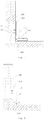
- the charging base 2 is fixed above the ground 200 and a bottom surface 23 of the charging base 2 is spaced apart from the ground 200.
- the charging base 2 is suspended relative to the ground just below the charging base 2, that is, the bottom surface 23 of the charging base 2 and the ground 200 just below the charging base 2 are spaced apart from each other.
- the "ground 200" used herein may be construed as an upper surface of a floor below the charging base 2, an upper surface of a tile, and certainly may also be an upper surface of a carpet, but is not limited thereto.
- the robot can clean the ground 200 below the charging base 2 because the bottom surface 23 of the charging base 2 is spaced apart from the ground 200.
- the spacing between the charging base 2 and the ground 200 should at least satisfy that a side brush can freely rotate in a vertical space between the charging base 2 and the ground 200 so that the dust located on the ground 200 below the charging base 2 can be fully cleaned.
- a distance between the bottom surface 23 of the charging base 2 and the ground 200 is not less than a height of the robot body 1. It should be noted herein that the height of the robot body 1 may be construed as a vertical distance between a top surface of the robot body 1 and the ground 200, when the robot body 1 is standing on the ground 200. As another alternative embodiment, the distance between the bottom surface 23 of the charging base 2 and the ground 200 is greater than the height of the robot body 1.
- the robot body 1 can move below the charging base 2 wholly so that the ground 200 below the charging base 2 can be completely and effectively cleaned. Furthermore, the charging base 2 is arranged to be suspended relative to the ground 200, therefore, the robot body 1 does not need to deliberately avoid the charging base 2 when the robot body 1 moves to an area adjacent to the charging base 2, and the ground 200 around the charging base 2 can also be effectively cleaned.
- the charging base 2 defines an accommodating portion 24.
- the accommodating portion 24 is used to accommodate the robot body 1 (as shown in Fig. 3 ), and the first charging terminal contacts the second charging terminal 21 to form an electrical connection after the robot body 1 is placed in the accommodating portion 24 so that the robot body 1 can be charged by the charging base 2.
- the robot body 1 may give an alert signal to the user, for example, transmit low-battery information to the user in the form of an alert light.
- the user can place the robot body 1 in the accommodating portion 24 so that the two charging terminals are interconnected to form an electrical connection, and further the robot body 1 may be charged by the charging base 2.
- the charging base 2 is arranged to be suspended relative to the ground 200 so that the side brush of the robot cleaner 100 can clean the ground 200 below the charging base 2, or the robot body 1 can directly move to the ground 200 below the charging base 2 to clean the ground 200. Therefore, part of the cleaning blind zone of the robot cleaner 100 is eliminated, the cleaning function of the robot cleaner 100 is enhanced, and the cleaning effect thereof is improved.
- the robot body 1 can be located in the accommodating portion 24 when the robot body 1 is being charged. That is, the robot body 1 is located above the ground 200 so that the ground 200 below the charging base 2 still can be effectively cleaned by the other robot cleaners or other forms of vacuum cleaners, without occurring that the ground 200 below the robot cleaner 100 cannot be cleaned because the robot cleaner 100 is placed on the ground 200.
- the charging base 2 may be directly attached to a wall 300 perpendicular to the ground 200.
- the wall 300 is generally provided with a socket 310 therein, the charging base 2 is configured to be positioned to the socket 310 and to be electrically connected to the socket 310.
- the charging base 2 may be provided with a plug pin, the plug pin can be plugged in a hole of the socket, the charging base 2 can be positioned to the wall 300 through a plug-in fit between the plug pin and the socket 310.
- the positioning of the charging base 2 can be achieved through the plug pin, and meanwhile the electrical connection to the socket 310 is achieved, which has a simple structure and easy maintenance.
- the fitting mode between the charging base 2 and the wall 300 is not limited to the plug-in fitting mode above.
- the charging base 2 may also be directly secured to the wall 300 or the socket 310 through a bolt or a screw.
- a separate support may be further disposed to the wall 300 or the socket 310, and the charging base 2 may also be fixed to the support, as long as the charging base 2 is ensured to be spaced apart from the ground 200 just below it.
- the charging base 2 is provided with a homing transmitting device 22, and the robot body 1 is provided with a homing receiving device matched with the homing transmitting device 22.
- the specific construction and work principle of the homing transmitting device 22 and the homing receiving device are known from the art, and have been widely applied to the existing robot cleaners and charging bases. Therefore, special description and limitation will not be made to the homing transmitting device 22 and the homing receiving device herein.
- the robot body 1 can automatically find the charging base 2 and return to the charging base 2 for charging when the battery of the robot body 1 is low.
- At least a portion of the second charging terminal 21 (e.g. the first charging sub-sheet 211) is configured to be a charging sheet extending inwardly into the accommodating portion 24.
- the first charging terminal of the robot body 1 can contact the said portion to form an electrical connection after the robot body 1 is placed in the accommodating portion 24 so that the robot body 1 can be charged by the charging base 2.
- the charging sheet may be a metal elastic sheet, which facilitates a butt connection, and ensures a reliable contact during the charging process.
- the second charging terminal 21 is configured to be a charging sheet, a first end of the charging sheet (e.g. a lower end) extends downward from a bottom surface of the charging base 2 to constitute a second charging sub-sheet 212, and a second end of the charging sheet (e.g. an upper end) extends inwardly into the accommodating portion 24 to constitute a first charging sub-sheet 211.
- a portion of the second charging terminal 21 according to the present embodiments extends inwardly into the accommodating portion 24 to form the first charging sub-sheet 211, and the other portion thereof may extend downward from the bottom surface of the charging base 2 and beyond the bottom surface 23 to form a second charging sub-sheet 212.
- the robot body 1 can be directly placed in the accommodating portion 24 by the user so that the first charging terminal of the robot body 1 can contact the portion 211 of the second charging terminal 21 extending into the accommodating portion 24 to form an electrical connection, and further the robot body 1 can be charged.
- the robot body 1 can also move below the charging base 2 by itself under the guidance of the homing transmitting device 22 so that the first charging terminal of the robot body 1 can contact the portion 212 of the second charging terminal 21 extending downward beyond the bottom surface 23 to form an electrical connection, and further the robot body 1 can be charged.
- the robot body 1 not only can the robot body 1 be charged by being manually picked and placed by the user, but the robot body 1 can also achieve an automatic charging process through automatic homing, which enriches the charging methods and improves the practicality of the robot cleaner 100.
- the charging base 2 may include a bottom plate portion 26, a first side plate portion 25 and a second side plate portion 27.
- the first side plate portion 25 and the second side plate portion 27 are disposed to a front side and a rear side of the bottom plate portion 26 respectively.
- the first side plate portion 25 and the second side plate portion 27 are opposite to each other and may be disposed in parallel, the first side plate portion 25, the second side plate portion 27 and the bottom plate portion 26 together define the above-described accommodating portion 24, and the accommodating portion 24 may be configured as a space having open top, open left and open right, but it is not limited thereto.
- a charging method of the robot body 1 is to be placed in the accommodating portion 24 (as shown in Fig. 3 ), in which case the weight of the robot body 1 and the charging base 2 may be fully carried by the charging base 2.
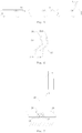
- a support structure 3 configured to support the charging base 2 may be disposed to the charging base 2. The support structure 3 may be supported on the ground 200 after the robot body 1 is placed in the accommodating portion 24, thereby improving the stability of the charging base 2.
- the support structure 3 is movable in an up-and-down direction relative to the charging base 2.
- the robot body 1 is configured to abut against the support structure 3 and drive the support structure 3 to move downward until the support structure 3 is supported on the ground 200 when the robot body 1 is placed downward in the accommodating portion 24.
- each group of the support structure 3 may include a support rob 31 and a spring 32.
- the spring 32 is fitted over the support rob 31, and an annular flange 311 may be disposed on an outer circumferential surface of the support rob 31.
- An upper end of the spring 32 elastically abuts against the annular flange 311 and a lower end of the spring 32 may elastically abut against an abutment surface 33 in the charging base 2.
- the spring 32 is normally in a compressed state to provide an upward elastic force applied on the support rob 31 so that an upper end of the support rob 31 can extend into the accommodating portion 24 through pushing effect of the spring in the condition that the support rod 31 is not subjected to other external forces.
- the robot body 1 When the robot body 1 is placed in the accommodating portion 24 by the user, as shown in Figs. 7 and 8 , the robot body 1 will abut against the upper end of the support rob 31 and push the support rob 31 to move downward until a bottom surface of the support rob 31 is supported on the ground so that the weight of the robot body 1 is at least partially shared by the support rob 31, and the stability of the charging base 2 is improved.
- a grip 11 may be disposed to the robot body 1.
- the grip 11 may be disposed to the casing of the robot body 1, for example, a containing groove may be disposed in the casing, and the grip 11 may be contained in the containing groove.
- the grip 11 can be firstly drawn and then turned relative to the robot body 1 so that the user can conveniently lift and pull the robot body 1 through the grip 11.
- a charging base 2 of a robot cleaner 100 will be described in detail below, and the charging base 2 is configured to charge the robot body 1 of the robot cleaner 100.
- the charging base 2 is fixed above the ground 200 and a bottom surface 23 of the charging base 2 is spaced apart from the ground 200.
- the charging base 2 is disposed to be suspended relative to the ground just below the charging base 2, that is, the bottom surface 23 of the charging base 2 and the ground 200 just below the charging base 2 are spaced apart from each other.
- the "ground 200" used herein may be construed as an upper surface of a floor below the charging base 2, an upper surface of a tile, and certainly may also be an upper surface of a carpet, but it is not limited thereto.
- the robot can clean the ground 200 below the charging base 2 because the bottom surface 23 of the charging base 2 is spaced apart from the ground 200.
- the spacing between the charging base 2 and the ground 200 should at least satisfy that a side brush can freely rotate in a vertical space between the charging base 2 and the ground 200 so that the dust located on the ground 200 below the charging base 2 can be fully cleaned.
- a distance between the bottom surface 23 of the charging base 2 and the ground 200 is not less than a height of the robot body 1. It should be noted herein that the height of the robot body 1 may be construed as a vertical distance between a top surface of the robot body 1 and the ground 200, when the robot body 1 is standing on the ground 200. As another alternative embodiment, the distance between the bottom surface 23 of the charging base 2 and the ground 200 is greater than the height of the robot body 1.
- the robot body 1 can move below the charging base 2 wholly so that the ground 200 below the charging base 2 can be completely and effectively cleaned. Furthermore, the charging base 2 is arranged to be suspended relative to the ground 200, therefore, the robot body 1 does not need to deliberately avoid the charging base 2 when the robot body 1 moves to an area adjacent to the charging base 2, and the ground 200 around the charging base 2 can also be effectively cleaned.
- the charging base 2 defines an accommodating portion 24.
- the accommodating portion 24 is used to accommodate the robot body 1 (as shown in Fig. 3 ), the charging base 2 may be provided with a charging terminal (i.e. the second charging terminal 21), and the charging terminal of the charging base 2 is configured to be matched with the charging terminal of the robot body 1 (i.e. the first charging terminal).
- the charging terminal of the charging base 2 contacts the charging terminal of the robot body 1 to form an electrical connection after the robot body 1 is placed in the accommodating portion 24, thus the robot body 1 can be charged by the charging base 2.
- At least a portion (e.g. the first charging sub-sheet 211) of the charging terminal of the charging base 2 is configured to be a charging sheet extending inwardly into the accommodating portion 24.
- the charging terminal of the robot body 1 can contact the said portion to form an electrical connection after the robot body 1 is placed in the accommodating portion 24 so that the robot body 1 can be charged by the charging base 2.
- the charging sheet may be a metal elastic sheet, which facilitates a butt connection, and ensures a reliable contact during the charging process.
- the charging terminal of the charging base 2 (i.e. the second charging terminal 21) is configured to be a charging sheet, a first end of the charging sheet (e.g. a lower end) extends downward from the bottom surface of the charging base 2 to constitute a second charging sub-sheet 212, and a second end of the charging sheet (e.g. an upper end) extends inwardly into the accommodating portion 24 to constitute a first charging sub-sheet 211.
- a portion of the charging terminal of the charging base 2 of the present embodiments extends inwardly into the accommodating portion 24 to form the first charging sub-sheet 211, and the other portion thereof may extend downward from the bottom surface of the charging base 2 and beyond the bottom surface 23 to form a second charging sub-sheet 212.
- the robot body 1 can be directly placed in the accommodating portion 24 by the user so that the charging terminal of the robot body 1 can contact the portion 211 of the charging terminal of charging base 2 extending into the accommodating portion 24 to form an electrical connection, and further the robot body 1 can be charged.
- the robot body 1 can also move below the charging base 2 by itself under the guidance of the homing transmitting device 22 so that the charging terminal of the robot body 1 can contact the portion 212 of the charging terminal of the charging base 2 extending downward beyond the bottom surface 23 to form an electrical connection, and further the robot body 1 can be charged.
- the charging base 2 may be directly attached to a wall 300 perpendicular to the ground 200.
- the wall 300 is generally provided with a socket 310 therein, the charging base 2 is configured to be positioned to the socket 310 and to be electrically connected to the socket 310.
- the charging base 2 may be provided with a plug pin, the plug pin can be plugged in a hole of the socket, the charging base 2 can be positioned to the wall 300 through a plug-in fit between the plug pin and the socket 310.
- the positioning of the charging base 2 can be achieved through the plug pin, and meanwhile the electrical connection to the socket 310 is achieved, which has a simple structure and easy maintenance.
- the fitting mode between the charging base 2 and the wall 300 is not limited to the plug-in fitting mode above.
- the charging base 2 may also be directly secured to the wall 300 or the socket 310 through a bolt or a screw.
- a separate support may be further disposed to the wall 300 or the socket 310, and the charging base 2 may also be fixed to the support, as long as the charging base 2 is ensured to be spaced apart from the ground 200 just below it.
- the charging base 2 is provided with a homing transmitting device 22, and the robot body 1 is provided with a homing receiving device matched with the homing transmitting device 22.
- the specific construction and work principle of the homing transmitting device 22 and the homing receiving device are known from the art, and have been widely applied to the existing robot cleaners and charging bases. Therefore, special description and limitation will not be made to the homing transmitting device 22 and the homing receiving device.
- the robot body 1 can automatically find the charging base 2 and return to the charging base 2 for charging when the battery of the robot body 1 is low.
- the charging base 2 may include a bottom plate portion 26, a first side plate portion 25 and a second side plate portion 27.
- the first side plate portion 25 and the second side plate portion 27 are disposed to a front side and a rear side of the bottom plate portion 26 respectively.
- the first side plate portion 25 and the second side plate portion 27 are opposite to each other and may be disposed in parallel, the first side plate portion 25, the second side plate portion 27 and the bottom plate portion 26 together define the above-described accommodating portion 24, and the accommodating portion 24 may be configured as a space having open top, open left and open right, but it is not limited thereto.
- a charging method of the robot body 1 is to be placed in the accommodating portion 24 (as shown in Fig. 3 ), in which case the weight of the robot body 1 and the charging base 2 may be fully carried by the charging base 2.
- a support structure 3 configured to support the charging base 2 may be disposed to the charging base 2. The support structure 3 may be supported on the ground 200 after the robot body 1 is placed in the accommodating portion 24, thereby improving the stability of the charging base 2.
- the support structure 3 is movable in an up-and-down direction relative to the charging base 2.
- the robot body 1 is configured to abut against the support structure 3 and drive the support structure 3 to move downward until the support structure 3 is supported on the ground 200 when the robot body 1 is placed downward in the accommodating portion 24.
- each group of the support structure 3 may include a support rob 31 and a spring 32.
- the spring 32 is fitted over the support rob 31, and an annular flange 311 may be disposed on an outer circumferential surface of the support rob 31.
- An upper end of the spring 32 elastically abuts against the annular flange 311 and a lower end of the spring 32 may elastically abut against an abutment surface 33 in the charging base 2.
- the spring 32 is normally in a compressed state to provide an upward elastic force applied on the support rob 31 so that an upper end of the support rob 31 can extend into the accommodating portion 24 through pushing effect of the spring in the condition that the support rod 31 is not subjected to other external forces.
- the robot body 1 When the robot body 1 is placed in the accommodating portion 24 by the user, as shown in Figs. 7 and 8 , the robot body 1 will abut against the upper end of the support rob 31 and push the support rob 31 to move downward until a bottom surface of the support rob 31 is supported on the ground so that the weight of the robot body 1 is at least partially shared by the support rob 31, and the stability of the charging base 2 is improved.
- a grip 11 may be disposed to the robot body 1.
- the grip 11 may be disposed to the casing of the robot body 1, for example, a containing groove may be disposed in the casing, and the grip 11 may be contained in the containing groove.
- the grip 11 can be firstly drawn and then turned relative to the robot body 1 so that the user can conveniently lift and pull the robot body 1 through the grip 11.
Landscapes
- Engineering & Computer Science (AREA)
- Power Engineering (AREA)
- Transportation (AREA)
- Mechanical Engineering (AREA)
- Charge And Discharge Circuits For Batteries Or The Like (AREA)
- Manipulator (AREA)
Applications Claiming Priority (2)
| Application Number | Priority Date | Filing Date | Title |
|---|---|---|---|
| CN201410572043.7A CN105581736B (zh) | 2014-10-23 | 2014-10-23 | 扫地机器人及其充电座 |
| PCT/CN2015/085473 WO2016062145A1 (fr) | 2014-10-23 | 2015-07-29 | Robot de nettoyage et sa base de charge |
Publications (3)
| Publication Number | Publication Date |
|---|---|
| EP3210516A1 true EP3210516A1 (fr) | 2017-08-30 |
| EP3210516A4 EP3210516A4 (fr) | 2018-06-06 |
| EP3210516B1 EP3210516B1 (fr) | 2021-07-14 |
Family
ID=55760255
Family Applications (1)
| Application Number | Title | Priority Date | Filing Date |
|---|---|---|---|
| EP15851697.1A Active EP3210516B1 (fr) | 2014-10-23 | 2015-07-29 | Robot de nettoyage et sa base de charge |
Country Status (4)
| Country | Link |
|---|---|
| EP (1) | EP3210516B1 (fr) |
| CN (1) | CN105581736B (fr) |
| ES (1) | ES2885855T3 (fr) |
| WO (1) | WO2016062145A1 (fr) |
Families Citing this family (18)
| Publication number | Priority date | Publication date | Assignee | Title |
|---|---|---|---|---|
| CN106214056A (zh) * | 2016-09-29 | 2016-12-14 | 深圳市宇辰智能科技有限公司 | 一种多功能擦拭机器人 |
| CN106214055A (zh) * | 2016-09-29 | 2016-12-14 | 深圳市宇辰智能科技有限公司 | 一种壁面清洁机器人 |
| US20200275815A1 (en) * | 2017-09-13 | 2020-09-03 | Chiba Institute Of Technology | Self-propelled vacuum cleaner |
| JP6655804B2 (ja) * | 2017-11-10 | 2020-02-26 | パナソニックIpマネジメント株式会社 | 移動ロボット、及び、移動ロボットの制御方法 |
| CN110200555B (zh) * | 2018-02-28 | 2021-10-22 | 杭州萤石软件有限公司 | 一种扫地机器人的充电方法和充电底座 |
| CN110403527B (zh) * | 2018-04-27 | 2021-11-12 | 杭州萤石软件有限公司 | 一种设备控制系统、方法及支撑设备和移动机器人 |
| JPWO2020084659A1 (ja) * | 2018-10-22 | 2021-09-02 | 学校法人千葉工業大学 | 格納装置 |
| KR101985314B1 (ko) * | 2018-10-29 | 2019-09-03 | 김정욱 | 전자동 로봇 청소장치 |
| CN111150329A (zh) * | 2018-11-08 | 2020-05-15 | 郑州雷动智能技术有限公司 | 一种自主移动充电设备的充电座 |
| CN111345738A (zh) * | 2018-12-21 | 2020-06-30 | 深圳市环球易购电子商务有限公司 | 扫地机回充座 |
| CN119138807A (zh) * | 2018-12-28 | 2024-12-17 | 云鲸智能创新(深圳)有限公司 | 基站 |
| CN110881906A (zh) * | 2019-12-10 | 2020-03-17 | 东莞芯速科技有限公司大岭山分公司 | 一种充电设备和扫地机器人 |
| CN111600363A (zh) * | 2020-06-18 | 2020-08-28 | 浙江芯球智能科技有限公司 | Agv机器人充电装置 |
| CN113261891B (zh) * | 2021-06-08 | 2025-09-05 | 尚科宁家(中国)科技有限公司 | 一种用于清洁机器人的基站 |
| CN113475987A (zh) * | 2021-08-17 | 2021-10-08 | 北京石头世纪科技股份有限公司 | 一种充电桩 |
| CN114041730B (zh) * | 2021-11-12 | 2022-12-16 | 东莞市茵莉电子有限公司 | 一种扫地机器人充电器 |
| CN114305221A (zh) * | 2021-12-17 | 2022-04-12 | 美智纵横科技有限责任公司 | 充电设备和扫地机器人 |
| CN114983299B (zh) * | 2022-06-06 | 2024-07-26 | 深圳银星智能集团股份有限公司 | 多清洁机器人的维护方法、清洁机器人、基站及清洁系统 |
Family Cites Families (9)
| Publication number | Priority date | Publication date | Assignee | Title |
|---|---|---|---|---|
| KR20050063547A (ko) * | 2003-12-22 | 2005-06-28 | 엘지전자 주식회사 | 로봇 청소기 및 그 운전방법 |
| KR200366079Y1 (ko) * | 2004-08-13 | 2004-10-28 | 엘지전자 주식회사 | 로봇청소기의 충전대 |
| US20060212191A1 (en) * | 2005-03-08 | 2006-09-21 | Funai Electric Co., Ltd. | Rechargeable traveling system |
| CN201469183U (zh) * | 2009-06-25 | 2010-05-19 | 泰怡凯电器(苏州)有限公司 | 地面处理系统 |
| USRE47264E1 (en) * | 2009-06-30 | 2019-03-05 | Lg Electronics Inc. | Charging device of robot cleaner |
| KR101021267B1 (ko) * | 2010-09-20 | 2011-03-11 | 주식회사 모뉴엘 | 청소로봇 시스템 및 그 제어 방법 |
| WO2012083589A1 (fr) * | 2010-12-20 | 2012-06-28 | 苏州宝时得电动工具有限公司 | Dispositif de marche automatique, système d'accueil et procédé d'accueil s'y rapportant |
| US9178370B2 (en) * | 2012-12-28 | 2015-11-03 | Irobot Corporation | Coverage robot docking station |
| CN204427948U (zh) * | 2015-01-21 | 2015-07-01 | 江苏美的春花电器股份有限公司 | 扫地机器人 |
-
2014
- 2014-10-23 CN CN201410572043.7A patent/CN105581736B/zh not_active Expired - Fee Related
-
2015
- 2015-07-29 WO PCT/CN2015/085473 patent/WO2016062145A1/fr not_active Ceased
- 2015-07-29 EP EP15851697.1A patent/EP3210516B1/fr active Active
- 2015-07-29 ES ES15851697T patent/ES2885855T3/es active Active
Also Published As
| Publication number | Publication date |
|---|---|
| EP3210516A4 (fr) | 2018-06-06 |
| WO2016062145A1 (fr) | 2016-04-28 |
| CN105581736A (zh) | 2016-05-18 |
| CN105581736B (zh) | 2018-06-08 |
| EP3210516B1 (fr) | 2021-07-14 |
| ES2885855T3 (es) | 2021-12-15 |
Similar Documents
| Publication | Publication Date | Title |
|---|---|---|
| EP3210516B1 (fr) | Robot de nettoyage et sa base de charge | |
| CN204427948U (zh) | 扫地机器人 | |
| KR102480693B1 (ko) | 진공 청소기 시스템 | |
| US20100139029A1 (en) | Wheel assembly and robot cleaner having the same | |
| EP2422675A2 (fr) | Robot nettoyeur doté d'un élément de décharge et son procédé de contrôle | |
| EP1806085A2 (fr) | Système robot nettoyeur | |
| WO2013162094A1 (fr) | Robot aspirateur | |
| JP2019509164A (ja) | 貯蔵システムの貯蔵格子を清掃するための清掃容器 | |
| CN105640441B (zh) | 扫地机器人 | |
| CN204722971U (zh) | 吸尘器 | |
| CN211534237U (zh) | 防潮垫和智能清洁系统 | |
| CN205814258U (zh) | 一种具有大垃圾处理装置的扫地机器人 | |
| CN212261269U (zh) | 清洁机器人及其边扫组件 | |
| JP2006204758A (ja) | ロボット掃除機 | |
| CN105640440B (zh) | 扫地机器人 | |
| US8769769B1 (en) | Floor cleaning apparatus | |
| CN105534408A (zh) | 一种全自动机器人吸尘器 | |
| CN105581734A (zh) | 扫地机器人及其充电座 | |
| CN204260676U (zh) | 扫地机器人 | |
| CN210961792U (zh) | 一种扫地机器人的防撞机构 | |
| CN204427947U (zh) | 扫地机器人的尘盒组件及具有它的扫地机器人 | |
| CN214128458U (zh) | 一种清扫机器人系统 | |
| CN105274951A (zh) | 一种仓场电动清洁推车 | |
| CN214205022U (zh) | 充电座及清洁系统 | |
| CN205319746U (zh) | 宽范围引导信号的机器人充电座 |
Legal Events
| Date | Code | Title | Description |
|---|---|---|---|
| STAA | Information on the status of an ep patent application or granted ep patent |
Free format text: STATUS: THE INTERNATIONAL PUBLICATION HAS BEEN MADE |
|
| PUAI | Public reference made under article 153(3) epc to a published international application that has entered the european phase |
Free format text: ORIGINAL CODE: 0009012 |
|
| STAA | Information on the status of an ep patent application or granted ep patent |
Free format text: STATUS: REQUEST FOR EXAMINATION WAS MADE |
|
| 17P | Request for examination filed |
Effective date: 20170523 |
|
| AK | Designated contracting states |
Kind code of ref document: A1 Designated state(s): AL AT BE BG CH CY CZ DE DK EE ES FI FR GB GR HR HU IE IS IT LI LT LU LV MC MK MT NL NO PL PT RO RS SE SI SK SM TR |
|
| AX | Request for extension of the european patent |
Extension state: BA ME |
|
| DAV | Request for validation of the european patent (deleted) | ||
| DAX | Request for extension of the european patent (deleted) | ||
| A4 | Supplementary search report drawn up and despatched |
Effective date: 20180507 |
|
| RIC1 | Information provided on ipc code assigned before grant |
Ipc: A47L 11/24 20060101AFI20180430BHEP |
|
| GRAP | Despatch of communication of intention to grant a patent |
Free format text: ORIGINAL CODE: EPIDOSNIGR1 |
|
| STAA | Information on the status of an ep patent application or granted ep patent |
Free format text: STATUS: GRANT OF PATENT IS INTENDED |
|
| GRAS | Grant fee paid |
Free format text: ORIGINAL CODE: EPIDOSNIGR3 |
|
| INTG | Intention to grant announced |
Effective date: 20210504 |
|
| GRAA | (expected) grant |
Free format text: ORIGINAL CODE: 0009210 |
|
| STAA | Information on the status of an ep patent application or granted ep patent |
Free format text: STATUS: THE PATENT HAS BEEN GRANTED |
|
| AK | Designated contracting states |
Kind code of ref document: B1 Designated state(s): AL AT BE BG CH CY CZ DE DK EE ES FI FR GB GR HR HU IE IS IT LI LT LU LV MC MK MT NL NO PL PT RO RS SE SI SK SM TR |
|
| REG | Reference to a national code |
Ref country code: GB Ref legal event code: FG4D |
|
| REG | Reference to a national code |
Ref country code: IE Ref legal event code: FG4D |
|
| REG | Reference to a national code |
Ref country code: DE Ref legal event code: R096 Ref document number: 602015071368 Country of ref document: DE |
|
| REG | Reference to a national code |
Ref country code: AT Ref legal event code: REF Ref document number: 1409992 Country of ref document: AT Kind code of ref document: T Effective date: 20210815 |
|
| REG | Reference to a national code |
Ref country code: NL Ref legal event code: FP |
|
| REG | Reference to a national code |
Ref country code: DE Ref legal event code: R081 Ref document number: 602015071368 Country of ref document: DE Owner name: MIDEA ROBOZONE TECHNOLOGY CO.LTD., SUZHOU, CN Free format text: FORMER OWNERS: JIANGSU MIDEA CLEANING APPLIANCES CO., LTD., SUZHOU, JIANGSU, CN; MIDEA GROUP CO., LTD., FOSHAN, GUANGDONG, CN |
|
| REG | Reference to a national code |
Ref country code: GB Ref legal event code: 732E Free format text: REGISTERED BETWEEN 20211007 AND 20211013 |
|
| REG | Reference to a national code |
Ref country code: LT Ref legal event code: MG9D |
|
| REG | Reference to a national code |
Ref country code: ES Ref legal event code: FG2A Ref document number: 2885855 Country of ref document: ES Kind code of ref document: T3 Effective date: 20211215 Ref country code: AT Ref legal event code: MK05 Ref document number: 1409992 Country of ref document: AT Kind code of ref document: T Effective date: 20210714 |
|
| REG | Reference to a national code |
Ref country code: ES Ref legal event code: PC2A Owner name: MIDEA ROBOZONE TECHNOLOGY CO., LTD. Effective date: 20220107 |
|
| PG25 | Lapsed in a contracting state [announced via postgrant information from national office to epo] |
Ref country code: HR Free format text: LAPSE BECAUSE OF FAILURE TO SUBMIT A TRANSLATION OF THE DESCRIPTION OR TO PAY THE FEE WITHIN THE PRESCRIBED TIME-LIMIT Effective date: 20210714 Ref country code: RS Free format text: LAPSE BECAUSE OF FAILURE TO SUBMIT A TRANSLATION OF THE DESCRIPTION OR TO PAY THE FEE WITHIN THE PRESCRIBED TIME-LIMIT Effective date: 20210714 Ref country code: SE Free format text: LAPSE BECAUSE OF FAILURE TO SUBMIT A TRANSLATION OF THE DESCRIPTION OR TO PAY THE FEE WITHIN THE PRESCRIBED TIME-LIMIT Effective date: 20210714 Ref country code: BG Free format text: LAPSE BECAUSE OF FAILURE TO SUBMIT A TRANSLATION OF THE DESCRIPTION OR TO PAY THE FEE WITHIN THE PRESCRIBED TIME-LIMIT Effective date: 20211014 Ref country code: AT Free format text: LAPSE BECAUSE OF FAILURE TO SUBMIT A TRANSLATION OF THE DESCRIPTION OR TO PAY THE FEE WITHIN THE PRESCRIBED TIME-LIMIT Effective date: 20210714 Ref country code: LT Free format text: LAPSE BECAUSE OF FAILURE TO SUBMIT A TRANSLATION OF THE DESCRIPTION OR TO PAY THE FEE WITHIN THE PRESCRIBED TIME-LIMIT Effective date: 20210714 Ref country code: NO Free format text: LAPSE BECAUSE OF FAILURE TO SUBMIT A TRANSLATION OF THE DESCRIPTION OR TO PAY THE FEE WITHIN THE PRESCRIBED TIME-LIMIT Effective date: 20211014 Ref country code: PT Free format text: LAPSE BECAUSE OF FAILURE TO SUBMIT A TRANSLATION OF THE DESCRIPTION OR TO PAY THE FEE WITHIN THE PRESCRIBED TIME-LIMIT Effective date: 20211115 Ref country code: FI Free format text: LAPSE BECAUSE OF FAILURE TO SUBMIT A TRANSLATION OF THE DESCRIPTION OR TO PAY THE FEE WITHIN THE PRESCRIBED TIME-LIMIT Effective date: 20210714 |
|
| REG | Reference to a national code |
Ref country code: NL Ref legal event code: PD Owner name: MIDEA ROBOZONE TECHNOLOGY CO., LTD.; CN Free format text: DETAILS ASSIGNMENT: CHANGE OF OWNER(S), ASSIGNMENT; FORMER OWNER NAME: MIDEA GROUP CO., LTD. Effective date: 20220105 |
|
| PG25 | Lapsed in a contracting state [announced via postgrant information from national office to epo] |
Ref country code: PL Free format text: LAPSE BECAUSE OF FAILURE TO SUBMIT A TRANSLATION OF THE DESCRIPTION OR TO PAY THE FEE WITHIN THE PRESCRIBED TIME-LIMIT Effective date: 20210714 Ref country code: LV Free format text: LAPSE BECAUSE OF FAILURE TO SUBMIT A TRANSLATION OF THE DESCRIPTION OR TO PAY THE FEE WITHIN THE PRESCRIBED TIME-LIMIT Effective date: 20210714 Ref country code: GR Free format text: LAPSE BECAUSE OF FAILURE TO SUBMIT A TRANSLATION OF THE DESCRIPTION OR TO PAY THE FEE WITHIN THE PRESCRIBED TIME-LIMIT Effective date: 20211015 |
|
| REG | Reference to a national code |
Ref country code: CH Ref legal event code: PL |
|
| REG | Reference to a national code |
Ref country code: BE Ref legal event code: MM Effective date: 20210731 |
|
| REG | Reference to a national code |
Ref country code: DE Ref legal event code: R097 Ref document number: 602015071368 Country of ref document: DE |
|
| PG25 | Lapsed in a contracting state [announced via postgrant information from national office to epo] |
Ref country code: LI Free format text: LAPSE BECAUSE OF NON-PAYMENT OF DUE FEES Effective date: 20210731 Ref country code: DK Free format text: LAPSE BECAUSE OF FAILURE TO SUBMIT A TRANSLATION OF THE DESCRIPTION OR TO PAY THE FEE WITHIN THE PRESCRIBED TIME-LIMIT Effective date: 20210714 Ref country code: CH Free format text: LAPSE BECAUSE OF NON-PAYMENT OF DUE FEES Effective date: 20210731 |
|
| PLBE | No opposition filed within time limit |
Free format text: ORIGINAL CODE: 0009261 |
|
| STAA | Information on the status of an ep patent application or granted ep patent |
Free format text: STATUS: NO OPPOSITION FILED WITHIN TIME LIMIT |
|
| PG25 | Lapsed in a contracting state [announced via postgrant information from national office to epo] |
Ref country code: SM Free format text: LAPSE BECAUSE OF FAILURE TO SUBMIT A TRANSLATION OF THE DESCRIPTION OR TO PAY THE FEE WITHIN THE PRESCRIBED TIME-LIMIT Effective date: 20210714 Ref country code: SK Free format text: LAPSE BECAUSE OF FAILURE TO SUBMIT A TRANSLATION OF THE DESCRIPTION OR TO PAY THE FEE WITHIN THE PRESCRIBED TIME-LIMIT Effective date: 20210714 Ref country code: RO Free format text: LAPSE BECAUSE OF FAILURE TO SUBMIT A TRANSLATION OF THE DESCRIPTION OR TO PAY THE FEE WITHIN THE PRESCRIBED TIME-LIMIT Effective date: 20210714 Ref country code: MC Free format text: LAPSE BECAUSE OF FAILURE TO SUBMIT A TRANSLATION OF THE DESCRIPTION OR TO PAY THE FEE WITHIN THE PRESCRIBED TIME-LIMIT Effective date: 20210714 Ref country code: LU Free format text: LAPSE BECAUSE OF NON-PAYMENT OF DUE FEES Effective date: 20210729 Ref country code: EE Free format text: LAPSE BECAUSE OF FAILURE TO SUBMIT A TRANSLATION OF THE DESCRIPTION OR TO PAY THE FEE WITHIN THE PRESCRIBED TIME-LIMIT Effective date: 20210714 Ref country code: CZ Free format text: LAPSE BECAUSE OF FAILURE TO SUBMIT A TRANSLATION OF THE DESCRIPTION OR TO PAY THE FEE WITHIN THE PRESCRIBED TIME-LIMIT Effective date: 20210714 Ref country code: AL Free format text: LAPSE BECAUSE OF FAILURE TO SUBMIT A TRANSLATION OF THE DESCRIPTION OR TO PAY THE FEE WITHIN THE PRESCRIBED TIME-LIMIT Effective date: 20210714 |
|
| 26N | No opposition filed |
Effective date: 20220419 |
|
| PG25 | Lapsed in a contracting state [announced via postgrant information from national office to epo] |
Ref country code: IE Free format text: LAPSE BECAUSE OF NON-PAYMENT OF DUE FEES Effective date: 20210729 Ref country code: BE Free format text: LAPSE BECAUSE OF NON-PAYMENT OF DUE FEES Effective date: 20210731 |
|
| PGFP | Annual fee paid to national office [announced via postgrant information from national office to epo] |
Ref country code: NL Payment date: 20220630 Year of fee payment: 8 Ref country code: IT Payment date: 20220628 Year of fee payment: 8 |
|
| PGFP | Annual fee paid to national office [announced via postgrant information from national office to epo] |
Ref country code: FR Payment date: 20220623 Year of fee payment: 8 |
|
| PGFP | Annual fee paid to national office [announced via postgrant information from national office to epo] |
Ref country code: GB Payment date: 20220706 Year of fee payment: 8 Ref country code: ES Payment date: 20220804 Year of fee payment: 8 Ref country code: DE Payment date: 20220608 Year of fee payment: 8 |
|
| PG25 | Lapsed in a contracting state [announced via postgrant information from national office to epo] |
Ref country code: HU Free format text: LAPSE BECAUSE OF FAILURE TO SUBMIT A TRANSLATION OF THE DESCRIPTION OR TO PAY THE FEE WITHIN THE PRESCRIBED TIME-LIMIT; INVALID AB INITIO Effective date: 20150729 |
|
| PG25 | Lapsed in a contracting state [announced via postgrant information from national office to epo] |
Ref country code: CY Free format text: LAPSE BECAUSE OF FAILURE TO SUBMIT A TRANSLATION OF THE DESCRIPTION OR TO PAY THE FEE WITHIN THE PRESCRIBED TIME-LIMIT Effective date: 20210714 |
|
| P01 | Opt-out of the competence of the unified patent court (upc) registered |
Effective date: 20230526 |
|
| REG | Reference to a national code |
Ref country code: DE Ref legal event code: R119 Ref document number: 602015071368 Country of ref document: DE |
|
| REG | Reference to a national code |
Ref country code: NL Ref legal event code: MM Effective date: 20230801 |
|
| GBPC | Gb: european patent ceased through non-payment of renewal fee |
Effective date: 20230729 |
|
| PG25 | Lapsed in a contracting state [announced via postgrant information from national office to epo] |
Ref country code: NL Free format text: LAPSE BECAUSE OF NON-PAYMENT OF DUE FEES Effective date: 20230801 |
|
| PG25 | Lapsed in a contracting state [announced via postgrant information from national office to epo] |
Ref country code: NL Free format text: LAPSE BECAUSE OF NON-PAYMENT OF DUE FEES Effective date: 20230801 Ref country code: MK Free format text: LAPSE BECAUSE OF FAILURE TO SUBMIT A TRANSLATION OF THE DESCRIPTION OR TO PAY THE FEE WITHIN THE PRESCRIBED TIME-LIMIT Effective date: 20210714 Ref country code: DE Free format text: LAPSE BECAUSE OF NON-PAYMENT OF DUE FEES Effective date: 20240201 Ref country code: GB Free format text: LAPSE BECAUSE OF NON-PAYMENT OF DUE FEES Effective date: 20230729 |
|
| PG25 | Lapsed in a contracting state [announced via postgrant information from national office to epo] |
Ref country code: FR Free format text: LAPSE BECAUSE OF NON-PAYMENT OF DUE FEES Effective date: 20230731 |
|
| PG25 | Lapsed in a contracting state [announced via postgrant information from national office to epo] |
Ref country code: IT Free format text: LAPSE BECAUSE OF NON-PAYMENT OF DUE FEES Effective date: 20230729 |
|
| REG | Reference to a national code |
Ref country code: ES Ref legal event code: FD2A Effective date: 20240902 |
|
| PG25 | Lapsed in a contracting state [announced via postgrant information from national office to epo] |
Ref country code: MT Free format text: LAPSE BECAUSE OF FAILURE TO SUBMIT A TRANSLATION OF THE DESCRIPTION OR TO PAY THE FEE WITHIN THE PRESCRIBED TIME-LIMIT Effective date: 20210714 |
|
| PG25 | Lapsed in a contracting state [announced via postgrant information from national office to epo] |
Ref country code: ES Free format text: LAPSE BECAUSE OF NON-PAYMENT OF DUE FEES Effective date: 20230730 |
|
| PG25 | Lapsed in a contracting state [announced via postgrant information from national office to epo] |
Ref country code: ES Free format text: LAPSE BECAUSE OF NON-PAYMENT OF DUE FEES Effective date: 20230730 |
|
| PG25 | Lapsed in a contracting state [announced via postgrant information from national office to epo] |
Ref country code: TR Free format text: LAPSE BECAUSE OF FAILURE TO SUBMIT A TRANSLATION OF THE DESCRIPTION OR TO PAY THE FEE WITHIN THE PRESCRIBED TIME-LIMIT Effective date: 20210714 |