EP3210521A1 - Instrument à tige endoscopique - Google Patents
Instrument à tige endoscopique Download PDFInfo
- Publication number
- EP3210521A1 EP3210521A1 EP17156366.1A EP17156366A EP3210521A1 EP 3210521 A1 EP3210521 A1 EP 3210521A1 EP 17156366 A EP17156366 A EP 17156366A EP 3210521 A1 EP3210521 A1 EP 3210521A1
- Authority
- EP
- European Patent Office
- Prior art keywords
- glass sleeve
- cover
- shaft
- glass
- shaft instrument
- Prior art date
- Legal status (The legal status is an assumption and is not a legal conclusion. Google has not performed a legal analysis and makes no representation as to the accuracy of the status listed.)
- Granted
Links
Images
Classifications
-
- A—HUMAN NECESSITIES
- A61—MEDICAL OR VETERINARY SCIENCE; HYGIENE
- A61B—DIAGNOSIS; SURGERY; IDENTIFICATION
- A61B1/00—Instruments for performing medical examinations of the interior of cavities or tubes of the body by visual or photographical inspection, e.g. endoscopes; Illuminating arrangements therefor
- A61B1/00064—Constructional details of the endoscope body
- A61B1/00071—Insertion part of the endoscope body
- A61B1/0008—Insertion part of the endoscope body characterised by distal tip features
- A61B1/00096—Optical elements
-
- A—HUMAN NECESSITIES
- A61—MEDICAL OR VETERINARY SCIENCE; HYGIENE
- A61B—DIAGNOSIS; SURGERY; IDENTIFICATION
- A61B1/00—Instruments for performing medical examinations of the interior of cavities or tubes of the body by visual or photographical inspection, e.g. endoscopes; Illuminating arrangements therefor
- A61B1/00112—Connection or coupling means
- A61B1/00114—Electrical cables in or with an endoscope
-
- A—HUMAN NECESSITIES
- A61—MEDICAL OR VETERINARY SCIENCE; HYGIENE
- A61B—DIAGNOSIS; SURGERY; IDENTIFICATION
- A61B1/00—Instruments for performing medical examinations of the interior of cavities or tubes of the body by visual or photographical inspection, e.g. endoscopes; Illuminating arrangements therefor
- A61B1/06—Instruments for performing medical examinations of the interior of cavities or tubes of the body by visual or photographical inspection, e.g. endoscopes; Illuminating arrangements therefor with illuminating arrangements
- A61B1/0661—Endoscope light sources
- A61B1/0676—Endoscope light sources at distal tip of an endoscope
-
- A—HUMAN NECESSITIES
- A61—MEDICAL OR VETERINARY SCIENCE; HYGIENE
- A61B—DIAGNOSIS; SURGERY; IDENTIFICATION
- A61B1/00—Instruments for performing medical examinations of the interior of cavities or tubes of the body by visual or photographical inspection, e.g. endoscopes; Illuminating arrangements therefor
- A61B1/06—Instruments for performing medical examinations of the interior of cavities or tubes of the body by visual or photographical inspection, e.g. endoscopes; Illuminating arrangements therefor with illuminating arrangements
- A61B1/0661—Endoscope light sources
- A61B1/0684—Endoscope light sources using light emitting diodes [LED]
-
- G—PHYSICS
- G02—OPTICS
- G02B—OPTICAL ELEMENTS, SYSTEMS OR APPARATUS
- G02B23/00—Telescopes, e.g. binoculars; Periscopes; Instruments for viewing the inside of hollow bodies; Viewfinders; Optical aiming or sighting devices
- G02B23/24—Instruments or systems for viewing the inside of hollow bodies, e.g. fibrescopes
- G02B23/2407—Optical details
- G02B23/2461—Illumination
-
- A—HUMAN NECESSITIES
- A61—MEDICAL OR VETERINARY SCIENCE; HYGIENE
- A61B—DIAGNOSIS; SURGERY; IDENTIFICATION
- A61B1/00—Instruments for performing medical examinations of the interior of cavities or tubes of the body by visual or photographical inspection, e.g. endoscopes; Illuminating arrangements therefor
- A61B1/00064—Constructional details of the endoscope body
- A61B1/0011—Manufacturing of endoscope parts
-
- H—ELECTRICITY
- H01—ELECTRIC ELEMENTS
- H01R—ELECTRICALLY-CONDUCTIVE CONNECTIONS; STRUCTURAL ASSOCIATIONS OF A PLURALITY OF MUTUALLY-INSULATED ELECTRICAL CONNECTING ELEMENTS; COUPLING DEVICES; CURRENT COLLECTORS
- H01R2201/00—Connectors or connections adapted for particular applications
- H01R2201/12—Connectors or connections adapted for particular applications for medicine and surgery
Definitions
- the invention relates to an endoscopic shaft instrument having the features specified in the preamble of claim 1.
- Starting point of the invention are those endoscopic instruments in which electronic components are arranged in the region of the distal end of a shaft to be introduced into the body of a patient.
- These electronic components may be part of a lighting or observation device and part of a therapy device, for example.
- the invention has the object to provide an endoscopic instrument of the type described above, which ensures sufficient electrical insulation of arranged in the region of the distal end of the instrument electronic components at the smallest possible lateral dimensions at its distal end portion.
- the endoscopic shaft instrument In the region of its distal end, ie in the region of the distal end of its shaft, the endoscopic shaft instrument according to the invention has at least one electronic component with an electrical conductor on the outside.
- the electronic component can, for. B. be part of a arranged in the distal end portion of the shaft lighting, observation or therapy device.
- the conductor located on the outside on the component is preferably used to supply the voltage to the component and is connected for this purpose to an electrical line leading to a voltage source and guided through the shaft.
- the peculiarity of the invention is that the at least one electronic component is surrounded at least externally by a glass sleeve.
- the shaft instrument according to the invention has several electronic components to be electrically insulated from the outside environment in the region of the distal end of its shaft, they can each be surrounded by a glass sleeve on the outside, or several electronic components can be surrounded by a glass sleeve on the outside, ie several in a glass sleeve be arranged electronic components.
- the sleeve which surrounds the outer circumference of the at least one electronic component is expediently arranged in the shaft in such a way that its central axis is aligned substantially parallel to the shaft center axis, that is to say in the case of the shaft.
- the wall of the glass sleeve is disposed between the electronic component with its external electrical conductor and the outer wall of the shaft and thus forms an electrical insulator arranged between the electronic component and the outer wall of the shaft, which is a current transfer from the electronic component or from the outside the component lying electrical conductor prevents the outer wall of the shaft.
- the glass sleeve can be made very thin-walled due to the good electrical insulation properties of glass and also very thin-walled produced. It can thus be provided an electrical insulation of the electronic component, which affects the radial dimensions of the shaft to a much lesser extent, as is the case with the known from the prior art endoscopic shaft instruments of the type in question.
- the glass sleeve is closed at its distal end by a cover.
- This design measure serves primarily to protect an arranged in the glass sleeve electronic component and is for example advantageous if the distal end of the shank instrument according to the invention is designed to be open in the direction of the electronic component.
- the component of the cover on the one hand mechanically protected and on the other hand shielded by possibly located in the outer environment of the distal end of the shaft fluids such as a flushing liquid used in conjunction with the shaft instrument, which otherwise also an undesirable current path from the electronic component to one with the Shank instrument to be treated patients and unwanted current paths on the electronic component itself could form.
- the cover is therefore preferably also formed of an electrically non-conductive material.
- a further advantage of the cover arranged at the distal end of the glass sleeve is that it stiffens the thin-walled glass sleeve and thus increases its stability.
- the covering the distal end of the glass sleeve cover is a glass cover.
- the use of a glass cover is typically useful when the electronic component disposed within the glass sleeve is a component for emitting or receiving light, the glass cover allowing light to pass from the electronic component to the distal exterior environment of the shank instrument and vice versa.
- the glass sleeve can be plane-parallel formed flat on its two flat sides or have to form a light-deflecting optical component, mutually obliquely aligned flat flat sides or on at least one of its flat sides have a convex or concave curvature.
- the glass sleeve and the cover are separate parts, which are materially interconnected.
- the cover can only be glued lying flat on the distal end of the glass sleeve with the glass sleeve.
- the cover engages with a corresponding with the inner cross section of the glass sleeve portion in the glass sleeve and is glued in this position with the glass sleeve, wherein the engaging in the distal end of the sleeve heel increases the stability of the glass sleeve to a particular extent.
- the use of separate, the glass sleeve and the cover forming parts is for example appropriate when a cover is provided, which is formed of a material other than glass or a combination of several materials. Regardless of whether the cover is formed of glass or another material or other materials, it proves to be advantageous that a glass sleeve closed distally from a cover when using two separate parts is relatively easy to produce by only one on the glass sleeve forming glass tube a covering forming plate must be stuck. With regard to a secure, stress-free adhesive bond between the glass sleeve and the cover, it is advantageous if the cover is formed of glass and thus with the glass sleeve identical or at least largely identical material properties such as having at least approximately the same coefficient of expansion.
- a monolithic component forms the glass sleeve and the cover. Accordingly, the electronic component is arranged in a sleeve-shaped and closed on a front side formed glass body. A loss of distal coverage is almost completely ruled out in this case.
- the glass sleeve may have a circular cross-section.
- the glass sleeve is preferably formed by a hollow cylindrical glass tube, which is inexpensive to produce and commercially available as semi-finished cost.
- the invention advantageously also provides embodiments of the glass sleeve, in which this has a deviating from a circular cross-section.
- the cross-sectional shape of the glass sleeve which is generally arbitrary, z. B. correspond to the cross-sectional dimensions of the electronic component disposed therein.
- the cross-sectional shape of the glass sleeve can also be adapted to further components of the endoscopic instrument, which are arranged in the cross-sectional direction of the shaft next to the glass sleeve or to channels extending through the shaft, such as working channels for carrying auxiliary instruments and / or rinsing fluid.
- the glass sleeve has a crescent-shaped cross section.
- the glass sleeve may have on its convexly curved outer side an outer radius which corresponds to the inner radius of the shank of the shank instrument, so that the glass sleeve can be arranged in the shank immediately adjacent to the inner wall of the shank, wherein a convexly curved outer side opposite concave curved area the outer side causes a comparatively large space for the arrangement of further components of the shaft instrument to be available in the shaft on the outside of the concavely curved region.
- the at least one outer circumference of a glass sleeve surrounding component is an LED.
- This LED is advantageously used to illuminate an area located on the distal side of the shaft instrument.
- the LED is furthermore preferably an LED chip which has at least one conductor arranged on the outside of the LED, which line connection connects a terminal contact provided on the light-emitting side to the LED to a pole of a DC voltage source.
- the glass sleeve and its distal cover shield the LED and in particular their outside conductors against the shaft of the shank instrument from electrically insulating, the glass sleeve and its cover also act to some extent thermally insulating, so that the radiated heat from the LED, especially at the same time Heat dissipation through the interior of the shaft in the proximal direction does not or only slightly reaches the radial and distal outer environment of the glass sleeve.
- a plurality of optical lenses are formed on the cover which preferably closes the glass sleeve at its distal end. Accordingly, a plurality of lenses are provided on the cover over the cross-sectional area distributed, which may be formed in a cover of a light transparent material by a corresponding bevel of the cover, but may also be formed by separate parts which are inserted in the cover or are placed on the cover.
- the lenses formed on the cover can be both collecting lenses and diverging lenses.
- the use of diverging lenses is particularly advantageous in connection with an LED of an illumination device arranged in the glass sleeve, in which a homogeneous distribution of the light emitted by the LED can be effected with the diverging lens.
- the lenses preferably concave lenses and preferably plano-concave lenses. In the latter case, it is primarily provided that a plurality of concave depressions are formed on the cover formed of a light-transmitting material on the flat side facing the glass sleeve.
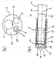
- Fig. 1 shows the distal end of a shaft 2 of an endoscopic shaft instrument. At this distal end of the shaft 2 opens a running through the entire shaft 2 working channel 4.
- the working channel 4 is primarily used to guide a used in conjunction with the shaft instrument, not shown auxiliary instrument to a distal side of the shaft 2 location.
- an image sensor unit 6 is arranged in the region of the distal end of the shaft 2 and an electronic component 10 in the form of an LED chip in a glass sleeve 8.
- the LED chip serves to illuminate a region located distally on the shaft 2.
- Glass sleeve 8 shown in detail which electrically isolates the LED chip arranged therein with respect to its outer environment, is formed as a hollow cylinder and closed by a cover 12 at its distal end.
- a cover 12 on the axially projecting cylindrical projection 14 whose outer diameter corresponds to the inner diameter of the glass sleeve 8 engages the glass formed cover 12 in the distal end of the glass sleeve 8, wherein a relation to the projection 14 radially enlarged portion 16 on the distal end of the glass sleeve 8 rests.
- the cover 12 is integrally connected to the glass sleeve 8 by means of an adhesive bond.
- the glass sleeve 8 is arranged such that a central axis A of the glass sleeve 8 is aligned parallel to a central axis B of the shaft 2.
- the glass sleeve 8 is arranged in the shaft 2 so that an outer side 18 of the glass sleeve 8 distal-closing cover 12 is flush with a distal end face 20 of the shaft 2.
- the LED chip is arranged in the glass sleeve 8 with a small distance to the cover 12 and is supported on the proximal side on a coaxial cable 22, which is guided through the entire shaft 2 and the LED chip with a proximal side of the shaft 2 arranged in the Drawing not shown DC voltage source connects.
- the coaxial cable 22 is shown cut, so that an inner conductor 28, an insulating sheath surrounding the inner conductor 22 on the outside 34, an outer conductor 32 and an outer insulation sheath 36 of the coaxial cable 22 become clear.
- the LED chip For electrical connection of the LED chip with the DC voltage source, the LED chip has on its light-emitting distal side 24 and on its proximal side 26 each have a connection contact, wherein the connection contacts are also not apparent from the drawing.
- the connection contact formed on the proximal side 26 of the LED chip is contacted by the inner conductor 28 of the coaxial cable 22, while the connection contact arranged on the distal side 24 of the LED chip is electrically conductively connected via a conductor 30 to an outer conductor 32 of the coaxial cable 22 ,
- the conductor 30 connecting the LED chip to the outer conductor 32 of the coaxial cable 22 is formed by a metallic sleeve.
- This sleeve is arranged so that it outside the LED chip, d. H. surrounds the outside and surrounds the outer conductor 32 of the coaxial cable 22 contacting in a distal end portion of the coaxial cable 22 on the outside. In this case, the sleeve is completely covered radially on the outside by the glass sleeve 8.
- the sleeve forming the conductor 30 has a web 38 protruding from the rest of the sleeve, which is angled transversely to the longitudinal extent of the sleeve for contacting the connection contact arranged on the distal side 24 of the LED chip.
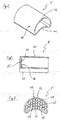
- the in the Fig. 3-5 illustrated glass sleeve 8 ' is also used for electrical shielding at least one in the glass sleeve 8' arranged LED chip 10 with respect to the outside environment.
- the glass sleeve 8 ' is monolithic, wherein a peripheral part 40 is closed at its distal end by a cover 12'.
- the cross section of the glass sleeve 8 ' is sickle-shaped, with a convex curved wall portion 42 rounded into a concave curved wall portion 44 passes.
- a plurality of concave recesses 48 are formed, each forming a plano-concave lens.
- plano-concave lenses serve to scatter the light emitted by at least one LED chip arranged in the glass sleeve 8 'on the distal side of the glass sleeve 8' so as to bring about a homogeneous light distribution.
Landscapes
- Health & Medical Sciences (AREA)
- Life Sciences & Earth Sciences (AREA)
- Surgery (AREA)
- Physics & Mathematics (AREA)
- Optics & Photonics (AREA)
- Engineering & Computer Science (AREA)
- Biomedical Technology (AREA)
- Molecular Biology (AREA)
- Pathology (AREA)
- Nuclear Medicine, Radiotherapy & Molecular Imaging (AREA)
- Biophysics (AREA)
- Heart & Thoracic Surgery (AREA)
- Medical Informatics (AREA)
- Radiology & Medical Imaging (AREA)
- Animal Behavior & Ethology (AREA)
- General Health & Medical Sciences (AREA)
- Public Health (AREA)
- Veterinary Medicine (AREA)
- Microelectronics & Electronic Packaging (AREA)
- Astronomy & Astrophysics (AREA)
- General Physics & Mathematics (AREA)
- Endoscopes (AREA)
Priority Applications (1)
| Application Number | Priority Date | Filing Date | Title |
|---|---|---|---|
| PL17156366T PL3210521T3 (pl) | 2016-02-24 | 2017-02-15 | Endoskopowy przyrząd przewodowy |
Applications Claiming Priority (1)
| Application Number | Priority Date | Filing Date | Title |
|---|---|---|---|
| DE102016202819.7A DE102016202819A1 (de) | 2016-02-24 | 2016-02-24 | Endoskopisches Schaftinstrument |
Publications (2)
| Publication Number | Publication Date |
|---|---|
| EP3210521A1 true EP3210521A1 (fr) | 2017-08-30 |
| EP3210521B1 EP3210521B1 (fr) | 2019-12-04 |
Family
ID=58054029
Family Applications (1)
| Application Number | Title | Priority Date | Filing Date |
|---|---|---|---|
| EP17156366.1A Active EP3210521B1 (fr) | 2016-02-24 | 2017-02-15 | Instrument à tige endoscopique |
Country Status (4)
| Country | Link |
|---|---|
| EP (1) | EP3210521B1 (fr) |
| DE (1) | DE102016202819A1 (fr) |
| ES (1) | ES2774129T3 (fr) |
| PL (1) | PL3210521T3 (fr) |
Cited By (1)
| Publication number | Priority date | Publication date | Assignee | Title |
|---|---|---|---|---|
| CN114222607A (zh) * | 2019-08-14 | 2022-03-22 | 理查德·沃尔夫有限公司 | 光治疗器 |
Citations (8)
| Publication number | Priority date | Publication date | Assignee | Title |
|---|---|---|---|---|
| US4778247A (en) * | 1984-05-04 | 1988-10-18 | Warner Lambert Technologies, Inc. | Molded objective head for fiberscopes with integral lenses |
| US5337734A (en) * | 1992-10-29 | 1994-08-16 | Advanced Polymers, Incorporated | Disposable sheath with optically transparent window formed continuously integral therewith |
| EP1467416A2 (fr) * | 2003-04-11 | 2004-10-13 | Weldon Technologies, Inc. | Diode électroluminescente de grande puissance |
| US20070249907A1 (en) * | 2006-04-20 | 2007-10-25 | Boulais Dennis R | Imaging assembly with transparent distal cap |
| CN201044740Y (zh) * | 2007-03-01 | 2008-04-09 | 范力 | 家用内窥镜 |
| DE102013201808A1 (de) * | 2013-02-05 | 2014-08-07 | Richard Wolf Gmbh | LED-Beleuchtungsmodul |
| US20150005580A1 (en) * | 2008-12-10 | 2015-01-01 | Ambu A/S | Endoscope having a camera housing and method for making a camera housing |
| CN204863074U (zh) * | 2015-06-26 | 2015-12-16 | 安姣 | 普内科用窥镜装置 |
Family Cites Families (3)
| Publication number | Priority date | Publication date | Assignee | Title |
|---|---|---|---|---|
| DD10387A5 (de) * | 1951-11-11 | 1955-09-01 | Firma Hans Kollmorgen Gmbh | BELEUCHTUNGSEINRICHTUNG FÜR UNTERSUCHUNGS- UND BEHANDLUNGSINSTRUMENTE FÜR HOHLRÄUME z.B. ANIMALISCHE KÖRPERHÖHLEN |
| JPH07104494B2 (ja) * | 1987-06-26 | 1995-11-13 | オリンパス光学工業株式会社 | 内視鏡用照明光学系 |
| DE20309759U1 (de) * | 2003-06-25 | 2003-09-04 | Richard Wolf Gmbh, 75438 Knittlingen | Medizinisches Endoskop |
-
2016
- 2016-02-24 DE DE102016202819.7A patent/DE102016202819A1/de not_active Withdrawn
-
2017
- 2017-02-15 ES ES17156366T patent/ES2774129T3/es active Active
- 2017-02-15 PL PL17156366T patent/PL3210521T3/pl unknown
- 2017-02-15 EP EP17156366.1A patent/EP3210521B1/fr active Active
Patent Citations (8)
| Publication number | Priority date | Publication date | Assignee | Title |
|---|---|---|---|---|
| US4778247A (en) * | 1984-05-04 | 1988-10-18 | Warner Lambert Technologies, Inc. | Molded objective head for fiberscopes with integral lenses |
| US5337734A (en) * | 1992-10-29 | 1994-08-16 | Advanced Polymers, Incorporated | Disposable sheath with optically transparent window formed continuously integral therewith |
| EP1467416A2 (fr) * | 2003-04-11 | 2004-10-13 | Weldon Technologies, Inc. | Diode électroluminescente de grande puissance |
| US20070249907A1 (en) * | 2006-04-20 | 2007-10-25 | Boulais Dennis R | Imaging assembly with transparent distal cap |
| CN201044740Y (zh) * | 2007-03-01 | 2008-04-09 | 范力 | 家用内窥镜 |
| US20150005580A1 (en) * | 2008-12-10 | 2015-01-01 | Ambu A/S | Endoscope having a camera housing and method for making a camera housing |
| DE102013201808A1 (de) * | 2013-02-05 | 2014-08-07 | Richard Wolf Gmbh | LED-Beleuchtungsmodul |
| CN204863074U (zh) * | 2015-06-26 | 2015-12-16 | 安姣 | 普内科用窥镜装置 |
Cited By (3)
| Publication number | Priority date | Publication date | Assignee | Title |
|---|---|---|---|---|
| CN114222607A (zh) * | 2019-08-14 | 2022-03-22 | 理查德·沃尔夫有限公司 | 光治疗器 |
| CN114222607B (zh) * | 2019-08-14 | 2024-02-06 | 理查德·沃尔夫有限公司 | 光治疗器 |
| US12318625B2 (en) | 2019-08-14 | 2025-06-03 | Richard Wolf Gmbh | Light applicator |
Also Published As
| Publication number | Publication date |
|---|---|
| DE102016202819A1 (de) | 2017-08-24 |
| EP3210521B1 (fr) | 2019-12-04 |
| PL3210521T3 (pl) | 2020-05-18 |
| ES2774129T3 (es) | 2020-07-16 |
Similar Documents
| Publication | Publication Date | Title |
|---|---|---|
| DE102013001156B4 (de) | Bipolares Resektoskop | |
| EP1153578B1 (fr) | Instrument chirurgical en forme de pince ou de ciseaux | |
| DE60123749T2 (de) | Endoskop mit reinigungsvorrichtung für beobachtungsfenster | |
| EP2476455A1 (fr) | Sonde implantable | |
| DE102007009725A1 (de) | Hochfrequenz-Behandlungsinstrument für ein Endoskop | |
| EP1296606A1 (fr) | Systeme d'electrodes d'un instrument chirurgical | |
| DE102007053398B4 (de) | Behandlungsinstrument für ein Endoskop | |
| EP3477784A1 (fr) | Dispositif de traitement pour un instrument médical microinvasif | |
| WO2014121960A1 (fr) | Module d'éclairage à led | |
| DE102019118824A1 (de) | Endoskop | |
| DE4125811A1 (de) | Laryngoskop mit einstellbarem blatt | |
| DE10042095C1 (de) | Urologisches Resektoskop mit Kontaktiereinrichtung | |
| EP3210521B1 (fr) | Instrument à tige endoscopique | |
| DE102010044786A1 (de) | Starres Videoendoskop mit isolierendem Leiterträger | |
| DE102011110136A1 (de) | Schaft eines laparoskopischen Instrumentes | |
| DE102019105564B4 (de) | Endoskop | |
| DE102011107783A1 (de) | Bipolares Resektoskop sowie Schlitten und Kabel dafür | |
| WO2009146790A1 (fr) | Canule, en particulier pour l’anesthésie locale | |
| DE102011105442A1 (de) | Arbeitseinsatz für ein endoskopisches Hohlschaftsinstrument | |
| DE3214487A1 (de) | Leitungsdurchfuehrung fuer hf-energie | |
| DE102016003177A1 (de) | Elektrode eines Resektoskopes | |
| DE2926919C2 (de) | Endoskop | |
| EP1897510A1 (fr) | Instrument endoscopique haute fréquence | |
| DE102010018818A1 (de) | Chirurgisches Instrument | |
| DE102021104865B4 (de) | Medizinisches Instrument |
Legal Events
| Date | Code | Title | Description |
|---|---|---|---|
| PUAI | Public reference made under article 153(3) epc to a published international application that has entered the european phase |
Free format text: ORIGINAL CODE: 0009012 |
|
| STAA | Information on the status of an ep patent application or granted ep patent |
Free format text: STATUS: THE APPLICATION HAS BEEN PUBLISHED |
|
| AK | Designated contracting states |
Kind code of ref document: A1 Designated state(s): AL AT BE BG CH CY CZ DE DK EE ES FI FR GB GR HR HU IE IS IT LI LT LU LV MC MK MT NL NO PL PT RO RS SE SI SK SM TR |
|
| AX | Request for extension of the european patent |
Extension state: BA ME |
|
| STAA | Information on the status of an ep patent application or granted ep patent |
Free format text: STATUS: REQUEST FOR EXAMINATION WAS MADE |
|
| 17P | Request for examination filed |
Effective date: 20180220 |
|
| RBV | Designated contracting states (corrected) |
Designated state(s): AL AT BE BG CH CY CZ DE DK EE ES FI FR GB GR HR HU IE IS IT LI LT LU LV MC MK MT NL NO PL PT RO RS SE SI SK SM TR |
|
| STAA | Information on the status of an ep patent application or granted ep patent |
Free format text: STATUS: EXAMINATION IS IN PROGRESS |
|
| 17Q | First examination report despatched |
Effective date: 20180622 |
|
| GRAP | Despatch of communication of intention to grant a patent |
Free format text: ORIGINAL CODE: EPIDOSNIGR1 |
|
| STAA | Information on the status of an ep patent application or granted ep patent |
Free format text: STATUS: GRANT OF PATENT IS INTENDED |
|
| INTG | Intention to grant announced |
Effective date: 20190712 |
|
| GRAS | Grant fee paid |
Free format text: ORIGINAL CODE: EPIDOSNIGR3 |
|
| GRAA | (expected) grant |
Free format text: ORIGINAL CODE: 0009210 |
|
| STAA | Information on the status of an ep patent application or granted ep patent |
Free format text: STATUS: THE PATENT HAS BEEN GRANTED |
|
| AK | Designated contracting states |
Kind code of ref document: B1 Designated state(s): AL AT BE BG CH CY CZ DE DK EE ES FI FR GB GR HR HU IE IS IT LI LT LU LV MC MK MT NL NO PL PT RO RS SE SI SK SM TR |
|
| REG | Reference to a national code |
Ref country code: GB Ref legal event code: FG4D Free format text: NOT ENGLISH |
|
| REG | Reference to a national code |
Ref country code: CH Ref legal event code: EP |
|
| REG | Reference to a national code |
Ref country code: AT Ref legal event code: REF Ref document number: 1208357 Country of ref document: AT Kind code of ref document: T Effective date: 20191215 |
|
| REG | Reference to a national code |
Ref country code: DE Ref legal event code: R096 Ref document number: 502017003018 Country of ref document: DE |
|
| REG | Reference to a national code |
Ref country code: IE Ref legal event code: FG4D Free format text: LANGUAGE OF EP DOCUMENT: GERMAN |
|
| REG | Reference to a national code |
Ref country code: CH Ref legal event code: NV Representative=s name: ISLER AND PEDRAZZINI AG, CH |
|
| REG | Reference to a national code |
Ref country code: SE Ref legal event code: TRGR |
|
| REG | Reference to a national code |
Ref country code: NL Ref legal event code: FP |
|
| REG | Reference to a national code |
Ref country code: LT Ref legal event code: MG4D |
|
| PG25 | Lapsed in a contracting state [announced via postgrant information from national office to epo] |
Ref country code: LT Free format text: LAPSE BECAUSE OF FAILURE TO SUBMIT A TRANSLATION OF THE DESCRIPTION OR TO PAY THE FEE WITHIN THE PRESCRIBED TIME-LIMIT Effective date: 20191204 Ref country code: NO Free format text: LAPSE BECAUSE OF FAILURE TO SUBMIT A TRANSLATION OF THE DESCRIPTION OR TO PAY THE FEE WITHIN THE PRESCRIBED TIME-LIMIT Effective date: 20200304 Ref country code: GR Free format text: LAPSE BECAUSE OF FAILURE TO SUBMIT A TRANSLATION OF THE DESCRIPTION OR TO PAY THE FEE WITHIN THE PRESCRIBED TIME-LIMIT Effective date: 20200305 Ref country code: LV Free format text: LAPSE BECAUSE OF FAILURE TO SUBMIT A TRANSLATION OF THE DESCRIPTION OR TO PAY THE FEE WITHIN THE PRESCRIBED TIME-LIMIT Effective date: 20191204 Ref country code: FI Free format text: LAPSE BECAUSE OF FAILURE TO SUBMIT A TRANSLATION OF THE DESCRIPTION OR TO PAY THE FEE WITHIN THE PRESCRIBED TIME-LIMIT Effective date: 20191204 Ref country code: BG Free format text: LAPSE BECAUSE OF FAILURE TO SUBMIT A TRANSLATION OF THE DESCRIPTION OR TO PAY THE FEE WITHIN THE PRESCRIBED TIME-LIMIT Effective date: 20200304 |
|
| PG25 | Lapsed in a contracting state [announced via postgrant information from national office to epo] |
Ref country code: RS Free format text: LAPSE BECAUSE OF FAILURE TO SUBMIT A TRANSLATION OF THE DESCRIPTION OR TO PAY THE FEE WITHIN THE PRESCRIBED TIME-LIMIT Effective date: 20191204 Ref country code: HR Free format text: LAPSE BECAUSE OF FAILURE TO SUBMIT A TRANSLATION OF THE DESCRIPTION OR TO PAY THE FEE WITHIN THE PRESCRIBED TIME-LIMIT Effective date: 20191204 |
|
| PG25 | Lapsed in a contracting state [announced via postgrant information from national office to epo] |
Ref country code: AL Free format text: LAPSE BECAUSE OF FAILURE TO SUBMIT A TRANSLATION OF THE DESCRIPTION OR TO PAY THE FEE WITHIN THE PRESCRIBED TIME-LIMIT Effective date: 20191204 |
|
| REG | Reference to a national code |
Ref country code: ES Ref legal event code: FG2A Ref document number: 2774129 Country of ref document: ES Kind code of ref document: T3 Effective date: 20200716 |
|
| PG25 | Lapsed in a contracting state [announced via postgrant information from national office to epo] |
Ref country code: PT Free format text: LAPSE BECAUSE OF FAILURE TO SUBMIT A TRANSLATION OF THE DESCRIPTION OR TO PAY THE FEE WITHIN THE PRESCRIBED TIME-LIMIT Effective date: 20200429 Ref country code: EE Free format text: LAPSE BECAUSE OF FAILURE TO SUBMIT A TRANSLATION OF THE DESCRIPTION OR TO PAY THE FEE WITHIN THE PRESCRIBED TIME-LIMIT Effective date: 20191204 Ref country code: RO Free format text: LAPSE BECAUSE OF FAILURE TO SUBMIT A TRANSLATION OF THE DESCRIPTION OR TO PAY THE FEE WITHIN THE PRESCRIBED TIME-LIMIT Effective date: 20191204 |
|
| PG25 | Lapsed in a contracting state [announced via postgrant information from national office to epo] |
Ref country code: SK Free format text: LAPSE BECAUSE OF FAILURE TO SUBMIT A TRANSLATION OF THE DESCRIPTION OR TO PAY THE FEE WITHIN THE PRESCRIBED TIME-LIMIT Effective date: 20191204 Ref country code: IS Free format text: LAPSE BECAUSE OF FAILURE TO SUBMIT A TRANSLATION OF THE DESCRIPTION OR TO PAY THE FEE WITHIN THE PRESCRIBED TIME-LIMIT Effective date: 20200404 Ref country code: SM Free format text: LAPSE BECAUSE OF FAILURE TO SUBMIT A TRANSLATION OF THE DESCRIPTION OR TO PAY THE FEE WITHIN THE PRESCRIBED TIME-LIMIT Effective date: 20191204 |
|
| REG | Reference to a national code |
Ref country code: DE Ref legal event code: R097 Ref document number: 502017003018 Country of ref document: DE |
|
| PLBE | No opposition filed within time limit |
Free format text: ORIGINAL CODE: 0009261 |
|
| STAA | Information on the status of an ep patent application or granted ep patent |
Free format text: STATUS: NO OPPOSITION FILED WITHIN TIME LIMIT |
|
| PG25 | Lapsed in a contracting state [announced via postgrant information from national office to epo] |
Ref country code: DK Free format text: LAPSE BECAUSE OF FAILURE TO SUBMIT A TRANSLATION OF THE DESCRIPTION OR TO PAY THE FEE WITHIN THE PRESCRIBED TIME-LIMIT Effective date: 20191204 Ref country code: MC Free format text: LAPSE BECAUSE OF FAILURE TO SUBMIT A TRANSLATION OF THE DESCRIPTION OR TO PAY THE FEE WITHIN THE PRESCRIBED TIME-LIMIT Effective date: 20191204 |
|
| 26N | No opposition filed |
Effective date: 20200907 |
|
| PG25 | Lapsed in a contracting state [announced via postgrant information from national office to epo] |
Ref country code: SI Free format text: LAPSE BECAUSE OF FAILURE TO SUBMIT A TRANSLATION OF THE DESCRIPTION OR TO PAY THE FEE WITHIN THE PRESCRIBED TIME-LIMIT Effective date: 20191204 |
|
| PG25 | Lapsed in a contracting state [announced via postgrant information from national office to epo] |
Ref country code: IE Free format text: LAPSE BECAUSE OF NON-PAYMENT OF DUE FEES Effective date: 20200215 |
|
| PG25 | Lapsed in a contracting state [announced via postgrant information from national office to epo] |
Ref country code: MT Free format text: LAPSE BECAUSE OF FAILURE TO SUBMIT A TRANSLATION OF THE DESCRIPTION OR TO PAY THE FEE WITHIN THE PRESCRIBED TIME-LIMIT Effective date: 20191204 Ref country code: CY Free format text: LAPSE BECAUSE OF FAILURE TO SUBMIT A TRANSLATION OF THE DESCRIPTION OR TO PAY THE FEE WITHIN THE PRESCRIBED TIME-LIMIT Effective date: 20191204 |
|
| PG25 | Lapsed in a contracting state [announced via postgrant information from national office to epo] |
Ref country code: MK Free format text: LAPSE BECAUSE OF FAILURE TO SUBMIT A TRANSLATION OF THE DESCRIPTION OR TO PAY THE FEE WITHIN THE PRESCRIBED TIME-LIMIT Effective date: 20191204 |
|
| REG | Reference to a national code |
Ref country code: AT Ref legal event code: MM01 Ref document number: 1208357 Country of ref document: AT Kind code of ref document: T Effective date: 20220215 |
|
| PG25 | Lapsed in a contracting state [announced via postgrant information from national office to epo] |
Ref country code: AT Free format text: LAPSE BECAUSE OF NON-PAYMENT OF DUE FEES Effective date: 20220215 |
|
| PGFP | Annual fee paid to national office [announced via postgrant information from national office to epo] |
Ref country code: LU Payment date: 20240220 Year of fee payment: 8 |
|
| PG25 | Lapsed in a contracting state [announced via postgrant information from national office to epo] |
Ref country code: LU Free format text: LAPSE BECAUSE OF NON-PAYMENT OF DUE FEES Effective date: 20250215 |
|
| REG | Reference to a national code |
Ref country code: CH Ref legal event code: U11 Free format text: ST27 STATUS EVENT CODE: U-0-0-U10-U11 (AS PROVIDED BY THE NATIONAL OFFICE) Effective date: 20260301 |
|
| PGFP | Annual fee paid to national office [announced via postgrant information from national office to epo] |
Ref country code: NL Payment date: 20260218 Year of fee payment: 10 |
|
| PGFP | Annual fee paid to national office [announced via postgrant information from national office to epo] |
Ref country code: SE Payment date: 20260218 Year of fee payment: 10 |
|
| PGFP | Annual fee paid to national office [announced via postgrant information from national office to epo] |
Ref country code: GB Payment date: 20260219 Year of fee payment: 10 |
|
| PGFP | Annual fee paid to national office [announced via postgrant information from national office to epo] |
Ref country code: ES Payment date: 20260319 Year of fee payment: 10 |
|
| PGFP | Annual fee paid to national office [announced via postgrant information from national office to epo] |
Ref country code: DE Payment date: 20260227 Year of fee payment: 10 |
|
| PGFP | Annual fee paid to national office [announced via postgrant information from national office to epo] |
Ref country code: BE Payment date: 20260218 Year of fee payment: 10 Ref country code: IT Payment date: 20260227 Year of fee payment: 10 |
|
| PGFP | Annual fee paid to national office [announced via postgrant information from national office to epo] |
Ref country code: FR Payment date: 20260223 Year of fee payment: 10 |
|
| PGFP | Annual fee paid to national office [announced via postgrant information from national office to epo] |
Ref country code: TR Payment date: 20260212 Year of fee payment: 10 |
|
| PGFP | Annual fee paid to national office [announced via postgrant information from national office to epo] |
Ref country code: CZ Payment date: 20260130 Year of fee payment: 10 Ref country code: CH Payment date: 20260301 Year of fee payment: 10 |
|
| PGFP | Annual fee paid to national office [announced via postgrant information from national office to epo] |
Ref country code: PL Payment date: 20260130 Year of fee payment: 10 |