EP3210657A1 - Dispositif de sauvetage pour un parc de loisirs - Google Patents
Dispositif de sauvetage pour un parc de loisirs Download PDFInfo
- Publication number
- EP3210657A1 EP3210657A1 EP16157957.8A EP16157957A EP3210657A1 EP 3210657 A1 EP3210657 A1 EP 3210657A1 EP 16157957 A EP16157957 A EP 16157957A EP 3210657 A1 EP3210657 A1 EP 3210657A1
- Authority
- EP
- European Patent Office
- Prior art keywords
- ride
- support structure
- recovery device
- along
- route
- Prior art date
- Legal status (The legal status is an assumption and is not a legal conclusion. Google has not performed a legal analysis and makes no representation as to the accuracy of the status listed.)
- Granted
Links
- 238000011084 recovery Methods 0.000 claims abstract description 42
- 238000012423 maintenance Methods 0.000 claims description 4
- 239000013598 vector Substances 0.000 claims description 4
- 230000001133 acceleration Effects 0.000 claims description 3
- 229910000831 Steel Inorganic materials 0.000 description 4
- 239000010959 steel Substances 0.000 description 4
- 230000000694 effects Effects 0.000 description 2
- 238000000034 method Methods 0.000 description 2
- 230000001174 ascending effect Effects 0.000 description 1
- 238000010276 construction Methods 0.000 description 1
- 239000004035 construction material Substances 0.000 description 1
- 230000001186 cumulative effect Effects 0.000 description 1
- 230000009977 dual effect Effects 0.000 description 1
- 230000005484 gravity Effects 0.000 description 1
- 230000007257 malfunction Effects 0.000 description 1
- 239000000463 material Substances 0.000 description 1
- 230000008447 perception Effects 0.000 description 1
- 230000002265 prevention Effects 0.000 description 1
- IHQKEDIOMGYHEB-UHFFFAOYSA-M sodium dimethylarsinate Chemical class [Na+].C[As](C)([O-])=O IHQKEDIOMGYHEB-UHFFFAOYSA-M 0.000 description 1
- 239000007787 solid Substances 0.000 description 1
- 239000000725 suspension Substances 0.000 description 1
- 238000003466 welding Methods 0.000 description 1
Images


Classifications
-
- A—HUMAN NECESSITIES
- A63—SPORTS; GAMES; AMUSEMENTS
- A63G—MERRY-GO-ROUNDS; SWINGS; ROCKING-HORSES; CHUTES; SWITCHBACKS; SIMILAR DEVICES FOR PUBLIC AMUSEMENT
- A63G21/00—Chutes; Helter-skelters
- A63G21/04—Chutes; Helter-skelters with fixed rails
-
- A—HUMAN NECESSITIES
- A62—LIFE-SAVING; FIRE-FIGHTING
- A62B—DEVICES, APPARATUS OR METHODS FOR LIFE-SAVING
- A62B3/00—Devices or single parts for facilitating escape from buildings or the like, e.g. protection shields, protection screens; Portable devices for preventing smoke penetrating into distinct parts of buildings
-
- A—HUMAN NECESSITIES
- A63—SPORTS; GAMES; AMUSEMENTS
- A63G—MERRY-GO-ROUNDS; SWINGS; ROCKING-HORSES; CHUTES; SWITCHBACKS; SIMILAR DEVICES FOR PUBLIC AMUSEMENT
- A63G7/00—Up-and-down hill tracks; Switchbacks
-
- B—PERFORMING OPERATIONS; TRANSPORTING
- B61—RAILWAYS
- B61B—RAILWAY SYSTEMS; EQUIPMENT THEREFOR NOT OTHERWISE PROVIDED FOR
- B61B5/00—Elevated railway systems without suspended vehicles
- B61B5/02—Elevated railway systems without suspended vehicles with two or more rails
-
- B—PERFORMING OPERATIONS; TRANSPORTING
- B61—RAILWAYS
- B61K—AUXILIARY EQUIPMENT SPECIALLY ADAPTED FOR RAILWAYS, NOT OTHERWISE PROVIDED FOR
- B61K13/00—Other auxiliaries or accessories for railways
Definitions
- the present invention relates to a ride with a carrying structure comprising at least one vehicle having a passenger name; at least one guide device, which is fastened to the carrying structure and forms a travel route, wherein the guide device is suitable for guiding the vehicle along the travel route; at least one drive element, which is suitable for the movement of the vehicle along the route; and at least one recovery device.
- the invention has for its object to provide a ride, in which the route offers a spectacular route and at the same time includes a recovery device that reaches almost every section of the route.
- a ride according to the invention with a particular tower-like support structure comprising at least one vehicle having a passenger receiving and at least one guide device which is attached to the support structure and forms a driving route, wherein the guide means for guiding the vehicle along the route suitable is.
- the ride has at least one drive element, which is suitable for movement of the vehicle along the route, and at least one recovery device with a driving range.
- the guide device is arranged at least in sections on a substantially vertical surface whose normal vector at each point perpendicular to the vertical axis of Carrying structure is and covers the area of access of the recovery device essentially the vertical surface.
- the (virtual) height axis intersects, viewed in a view from above or from below, the surface of the support structure forming the (projected) top and / or base, for example in a central region, e.g. in a center of gravity of the projected surface.
- the height axis is perpendicular, or aligned perpendicular to the horizontal surface of the earth.
- the support structure is vertically oriented and may include a tower, or tower-like building structure (e.g., scaffolding), or any other building, e.g. a skyscraper or a pyramidal building etc., form.
- the support structure is preferably made of steel, but may also be made of other suitable construction materials, e.g. Concrete, etc., exist.
- the support structure can be mounted permanently stationary. Alternatively, the support structure may be designed for temporary assembly and disassembly, e.g. if the ride is going to different places.
- the vehicle according to the invention is suitable for accommodating at least one passenger. It is conceivable an arrangement of at least two passengers next to each other and / or an arrangement in a row.
- the passenger seat has a corresponding receiving device and can be, inter alia, an open seat construction or a closed cabin with appropriate securing means for the passengers.
- the guide device preferably consists of at least one rail or two parallel rails, through which the vehicle is held and guided along the route formed thereby.
- a guide structure comprising a corresponding receptacle for a chassis of the vehicle, e.g. a trough structure.
- the guide device is attached to the support structure. All common and known attachment methods are used, e.g. Screwing, welding, riveting, etc.
- the attachment can be permanent or temporary, for example, if the ride is operated only temporarily and several times to build up and dismantle.
- the guide device can be erected together with the support structure. Alternatively, the guide device can also be added later to an existing building structure.
- the guide device is formed into a closed route, whereby the vehicle or vehicles can run in a circle.
- the route may only be finite (e.g., only on one side of the support structure), after which the vehicle or vehicles operate in directional traffic (point to point).
- Both the underside or the top of the vehicle can be guided by the guide device.
- the guidance at the top, or above the passenger seat increases the entertainment effect, since the route disappears from the direct field of vision and thus from the perception of the passenger and a free movement is suggested. It is conceivable next to a lateral guidance of the vehicle.
- the guide device is arranged at least in sections on a substantially vertical surface whose normal vector is perpendicular to the height axis of the support structure at each point.
- the vertical surface does not have to be completed, but is largely determined by the underlying support structure, which defines a vertical enveloping surface.
- a vertical surface may also include tolerance angles of up to +/- 10 degrees (80/100 degrees).
- the route formed by the guide device can be guided essentially in a straight line or have a tortuous structure.
- the drive element according to the invention for moving the vehicle can be located on the vehicle itself (actively driven vehicle) or at corresponding points of the driving route (passively driven vehicle), primarily on inclines or in the driveway. Conceivable here are all current and conceivable drive elements.
- the mountain element is used to access the route from the outside and is thus designed and has a driving range, which is designed so that almost all areas of the route can be achieved. In this way, especially the salvage of passengers or vehicles can be done, which have stopped due to a disturbance in an area of the route.
- the movement of the vehicle generated by the drive element is an acceleration and / or a deceleration.
- the acceleration takes place in the driveway of the vehicle or vehicles and the delay in the departure. In the latter case energy can be recovered due to the delay (recuperation).
- the drive element is preferably a gear connection, a cable connection, a chain connection, a friction wheel drive or a linear drive.
- the provided force should be as completely as possible translated into the corresponding forms of movement.
- the vehicle has a chassis, which is arranged to be movable, in particular rotatable, relative to the passenger compartment.
- the vehicle In order to realize a closed route with up-and-down and to avoid that the vehicle gets into an overhead position when changing from an up to a downhill, the vehicle is preferably rotatably mounted on the chassis. In this way, unwanted overhead positions can be avoided. In addition, can be achieved in relation to the route with a rotatably mounted and guided above the passenger seat vehicle compensation, or a swinging out according to the heavy or weight of the vehicle. In addition, the vehicle due to centrifugal forces caused by the curve movements swing out.
- the route is at least partially guided substantially vertically parallel to the vertical axis of the support structure.
- the guide track can be performed in extreme cases and with the shortest distance in a straight line (thus perpendicular, or perpendicular to the perpendicular at 90 degrees to the horizontal).
- An angular deviation of up to +/- 10 degrees (80/100 degrees) is still to be understood as vertical within the meaning of the invention.
- the route is essentially spiraling and / or descending guided around the vertical axis of the support structure.
- the recovery device according to the invention is designed in particular for recovery and / or maintenance of the route.
- the recovery device can reach nearly every section of the route or the vertical outer surface of the tower-like support structure, the device is also suitable for maintenance work on the route as well as the support structure in addition to recovery in the event of a fault.
- the recovery device preferably comprises a fastening device attached to the support structure, a platform and / or a car and a carrying device, which is provided for carrying and moving the platform along a travel path, wherein the travel distance is arranged in particular vertically along the height of the support structure and the platform, or the car along the trajectory is movable.
- the recovery device is attached to the support structure via the fastening device by means of common and all conceivable attachment methods.
- the platform, or the car extends along the width of the support structure and is on the one hand for receiving rescue personnel in case of failure or personnel in the event of maintenance and repair and on the other to accommodate the rescued passengers.
- the car is connected to a carrying device, whereby the car along the height axis of the support structure on a (substantially vertical) travel path is movable. As a result, almost all areas of the route can be reached on one level along the travel path.
- the fastening device may for example be a boom, which is arranged at the upper edge region of the support structure and projects at least partially beyond the edge of the upper side of the support structure to the outside.
- the recovery device can be attached vertically movably to the attachment device, e.g. by one or more suspension cables.
- the fastening device of the recovery device is arranged at the top and / or at the bottom of the support structure.
- the attachment of the recovery device can be carried out at the top of the support structure, after which the travel distance formed by the support device extends from the top, that is vertical to the bottom.
- the travel path can run vertically from the underside to the top of the support structure. Also possible is the cumulative attachment to the top and bottom of the support structure.
- the carrying device of the recovery device preferably comprises at least one cable (for example steel cable) and / or at least one tube and / or a support rod (telescope).
- cable for example steel cable
- tube for example steel tube
- support rod telescope
- the recovery device has a drive element which is suitable for moving the platform or the car along the travel path of the carrying device.
- the drive element may be attached to the platform or to the car itself. Alternatively, the drive may also be attached to the support structure in the region of attachment to the top or bottom (e.g., powered winch).
- the fastening device of the recovery device is movable along the circumference of the upper side of the support structure and / or around the underside of the support structure.
- the fastening device is thereby guided, inter alia, by appropriate devices for guiding, eg rails, etc., along the circumference of the support structure.
- additional Movement can be superimposed on the linear motion along the height of the support structure with a horizontal movement.
- each area and especially each side of the support structure can be achieved. This is particularly advantageous when the route is guided along the sides of the support structure or several routes are used.
- the recovery device preferably comprises a drive device for moving the recovery device along the circumference of the support structure and / or for moving the platform along the travel path of the support device.
- another or the same drive element can effect the movement along the circumference of the support structure.
- the recovery device has an extendable arm.
- the boom serves to extend the scope of the platform in order to reach a bit further inside and outside the actual trajectory lying route sections with the platform can.
- the vertical projection of the trajectory then gives no point in the horizontal plane, but a band of width B corresponding to the boom traverse, i. the traversing space would be a solid of width B with parallel vertical surfaces whose normal vectors are perpendicular (90 °) to the tower axis direction at each point.
- a driving shop system consists of at least two rides according to the invention, wherein the routes of the rides run on one or more horizontal and / or one or more vertical planes of the at least two carrying structures.
- rides can also be fastened in a carrier structure according to the invention with a plurality of traffic facilities and a plurality of traffic levels (or traffic areas).
- a vehicle can be located on the outside of the tower-like support structure and another vehicle on the inside.
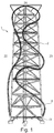
- FIG. 1 is an overall view of a ride 1 according to the invention with a tower-like support structure 2 recognizable.
- the tower of the support structure 2 consists of a truss structure, which is formed of individual steel elements.
- the support structure 2 is slightly tapered in the vertical direction up to the top 24.
- the guide device 4 in the form of two parallel guide rails and a support rail with support structure is attached to the support structure 2.
- the route formed by the guide device 4 is a closed route.
- the route starts in a station area to the entry / exit of the passengers (not shown) on the underside 21 of the support structure and performs on the right side 23 an uplink in a multi-threaded structure to from the top 24 of the support structure 2 on the left side 22 to go into a nearly vertically downhill route.
- vehicles 3 are guided along the route, which serve to accommodate passengers.
- the guidance of the vehicles 3 takes place above the passenger compartment.
- the recovery device 5 is attached, which is not further illustrated.
- the recovery device 5 is shown, which is fastened to the upper side 24 of the support structure 2 by a fastening device 52.
- Two parallel ropes form a carrying device 53, to which a platform 51 or a car is attached.
- the carrying device 53 is designed and movable such that a movement of the platform or of the car along a travel path 54 along the vertical plane of the carrying structure 2 is made possible.
- FIG. 3 shows the fastening device 52 of the recovery device 5, which is arranged on the upper side 24 of the support structure 2.
- the fastening device 52 is movable along the circumference of the surface 24 of the support structure 2, whereby each side of the support structure 2 can be reached.
- FIGS. 4A and 4B the platform 51 of the recovery device 5 is shown.
- the platform 51 which is fixed on both sides on the broad side with the support means 53, in the form of two ropes, recognizable.
- the platform 51 or the car on a boom 55.
- the boom 55 is extendable along the broad side of the platform 51 and thus increases the surface of the platform 51.
- an extensibility along the longitudinal side of the Platform 51 possible. In this meadow, the sphere of influence that can be reached through the platform is increased.
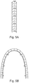
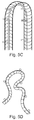
- FIGS. 5A to 5D show various arrangements of the driving route, which is formed by the guide means 4 and is arranged in a substantially vertical surface. Two rails are guided in parallel on a support rail. The support rail is connected to the carrying device 53.
- FIG. 5A shows a straight track layout. In this case, only a movement of the vehicle or vehicles 3 in the form of a round trip, eg from the bottom 21 of the support means 53 to the top 24 is possible.
- FIG. 5B shows a plan view of the route arrangement in the form of a wave.
- FIG. 5C shows a side view of the waveform of the route.
- FIG. 5D shows a plan view of an intricate shape of the route.
- FIGS. 5B and 5D show that the vertical area of the access area does not have to be a plane but also contains curved areas, such as in the form of a wave ( FIG. 5B ) or in the form of a tangled shape ( FIG. 5D ).
Landscapes
- Engineering & Computer Science (AREA)
- Mechanical Engineering (AREA)
- Health & Medical Sciences (AREA)
- General Health & Medical Sciences (AREA)
- Business, Economics & Management (AREA)
- Emergency Management (AREA)
- Transportation (AREA)
- Platform Screen Doors And Railroad Systems (AREA)
- Jib Cranes (AREA)
- Emergency Lowering Means (AREA)
Priority Applications (3)
| Application Number | Priority Date | Filing Date | Title |
|---|---|---|---|
| EP16157957.8A EP3210657B1 (fr) | 2016-02-29 | 2016-02-29 | Dispositif de sauvetage pour un parc de loisirs |
| CN201710094450.5A CN107126705B (zh) | 2016-02-29 | 2017-02-21 | 游乐场过山车 |
| US15/445,603 US10406386B2 (en) | 2016-02-29 | 2017-02-28 | Recovery device for an amusement ride |
Applications Claiming Priority (1)
| Application Number | Priority Date | Filing Date | Title |
|---|---|---|---|
| EP16157957.8A EP3210657B1 (fr) | 2016-02-29 | 2016-02-29 | Dispositif de sauvetage pour un parc de loisirs |
Publications (2)
| Publication Number | Publication Date |
|---|---|
| EP3210657A1 true EP3210657A1 (fr) | 2017-08-30 |
| EP3210657B1 EP3210657B1 (fr) | 2019-08-07 |
Family
ID=55443202
Family Applications (1)
| Application Number | Title | Priority Date | Filing Date |
|---|---|---|---|
| EP16157957.8A Active EP3210657B1 (fr) | 2016-02-29 | 2016-02-29 | Dispositif de sauvetage pour un parc de loisirs |
Country Status (3)
| Country | Link |
|---|---|
| US (1) | US10406386B2 (fr) |
| EP (1) | EP3210657B1 (fr) |
| CN (1) | CN107126705B (fr) |
Families Citing this family (5)
| Publication number | Priority date | Publication date | Assignee | Title |
|---|---|---|---|---|
| US11607619B2 (en) * | 2018-10-02 | 2023-03-21 | Universal City Studios Llc | Ride evacuation systems and methods |
| RU197857U1 (ru) * | 2019-12-18 | 2020-06-03 | Валерий Павлович Левицкий | Устройство для эвакуации людей с кровли высотных зданий |
| DE102021121045A1 (de) * | 2021-08-12 | 2023-02-16 | Mack Rides Ip Gmbh & Co. Kg | Vergnügungs-Fahrgeschäft und Verfahren zum Betrieb eines Vergnügungs-Fahrgeschäfts |
| GB2619705B (en) * | 2022-06-08 | 2025-07-16 | Castree Projects Ltd | Apparatus and method |
| US12605638B1 (en) * | 2025-09-02 | 2026-04-21 | Luke Horwath | Modular roller coaster |
Citations (5)
| Publication number | Priority date | Publication date | Assignee | Title |
|---|---|---|---|---|
| US20020103033A1 (en) * | 2000-09-08 | 2002-08-01 | Werner Stengel | Free-fall tower for a roller coaster |
| EP1721647A1 (fr) * | 2005-05-12 | 2006-11-15 | Vekoma Rides Engineering B.V. | Dispositif de divertissement |
| DE202010008641U1 (de) * | 2010-09-28 | 2010-11-18 | Walser, Willy | Vorrichtung zum Transport von Fahrzeugen einer spurgeführten Vergnügungsbahn |
| WO2015073998A1 (fr) * | 2013-11-17 | 2015-05-21 | Kitchen William J | Pistes et entraînement pour un manège en forme de tour |
| CN204395421U (zh) * | 2015-02-03 | 2015-06-17 | 万达文化旅游规划研究院有限公司 | 双轨对战过山车 |
Family Cites Families (4)
| Publication number | Priority date | Publication date | Assignee | Title |
|---|---|---|---|---|
| US8453577B2 (en) * | 2007-10-11 | 2013-06-04 | Jonathan I. Gordon | Roller coaster maintenance vehicle and methods of use |
| CN202113506U (zh) * | 2011-04-21 | 2012-01-18 | 张晓冰 | 高层灭火救生维修机器人 |
| BR112013030187A2 (pt) * | 2011-05-26 | 2018-04-24 | J Kitchen William | pista para torre |
| CN204447275U (zh) * | 2015-02-02 | 2015-07-08 | 万德沃(北京)游乐设施发展有限公司 | 一种过山车提升最高处救援装置 |
-
2016
- 2016-02-29 EP EP16157957.8A patent/EP3210657B1/fr active Active
-
2017
- 2017-02-21 CN CN201710094450.5A patent/CN107126705B/zh not_active Expired - Fee Related
- 2017-02-28 US US15/445,603 patent/US10406386B2/en not_active Expired - Fee Related
Patent Citations (5)
| Publication number | Priority date | Publication date | Assignee | Title |
|---|---|---|---|---|
| US20020103033A1 (en) * | 2000-09-08 | 2002-08-01 | Werner Stengel | Free-fall tower for a roller coaster |
| EP1721647A1 (fr) * | 2005-05-12 | 2006-11-15 | Vekoma Rides Engineering B.V. | Dispositif de divertissement |
| DE202010008641U1 (de) * | 2010-09-28 | 2010-11-18 | Walser, Willy | Vorrichtung zum Transport von Fahrzeugen einer spurgeführten Vergnügungsbahn |
| WO2015073998A1 (fr) * | 2013-11-17 | 2015-05-21 | Kitchen William J | Pistes et entraînement pour un manège en forme de tour |
| CN204395421U (zh) * | 2015-02-03 | 2015-06-17 | 万达文化旅游规划研究院有限公司 | 双轨对战过山车 |
Also Published As
| Publication number | Publication date |
|---|---|
| US10406386B2 (en) | 2019-09-10 |
| EP3210657B1 (fr) | 2019-08-07 |
| US20170246484A1 (en) | 2017-08-31 |
| CN107126705A (zh) | 2017-09-05 |
| CN107126705B (zh) | 2020-10-20 |
Similar Documents
| Publication | Publication Date | Title |
|---|---|---|
| EP3210657B1 (fr) | Dispositif de sauvetage pour un parc de loisirs | |
| EP2277760B1 (fr) | Dispositif de transport avec un vehicule et une voie comprenant deux rails de guidage superposés | |
| DE3206630C2 (fr) | ||
| EP3691985A1 (fr) | Procédé pour construire un système d'ascenseur présentant une hauteur de levage utile croissante | |
| DE60201341T2 (de) | Hochbahn | |
| WO2018234351A1 (fr) | Système d'ascenseur | |
| DE202015005139U1 (de) | Elektrohängebahn in Leichtausführung zum hängenden Transport von Lasten bei Handel und Industrie | |
| DE3018009A1 (de) | Schienenbahn fuer den transport von personen und guetern | |
| AT522165B1 (de) | Seilbahnstütze mit einer Überstiegsvorrichtung | |
| EP0185973A2 (fr) | Voie pour véhicule d'un chemin de fer d'attraction transportant des passagers | |
| EP1845005A2 (fr) | Véhicule sur rails et transport ferroviaire | |
| DE60106969T2 (de) | Rolltreppe zur bewegung um kurven | |
| EP3960264B1 (fr) | Véhicule tractant | |
| DE102006032239A1 (de) | Seilbahn mit veränderbarer Tragseillage | |
| EP1034996B1 (fr) | Station de départ et d'arrivée pour un téléphérique à deux cables et une cabine pour le transport des passagers qui montent et descendent dans une telle station | |
| EP1647514B1 (fr) | Ascenseur incliné | |
| DE202010008641U1 (de) | Vorrichtung zum Transport von Fahrzeugen einer spurgeführten Vergnügungsbahn | |
| EP3554912B1 (fr) | Système de transport comprenant un véhicule tracté par câble | |
| EP0195370A2 (fr) | Ascenseur de transport de personnes ou de charges avec une cabine en forme d'anneau | |
| DE19827037A1 (de) | Verfahren und Einrichtung zur Beförderung von Personen, vorzugsweise einschließlich Fahrrädern und/oder Rollstühlen, und/oder Personen- und/oder Lastkraftfahrzeugen und/oder zum Transport von Gegenständen und/oder von Material | |
| DE202009009728U1 (de) | Fahrzeug zur Durchführung von Baumaßnahmen im Gleisbereich des Eisenbahnverkehrs | |
| DE3142790C2 (fr) | ||
| DE2832991A1 (de) | Kettenaufzug fuer aneinandergekuppelte fahrzeuggruppen von belustigungsvorrichtungen | |
| DE102009033516A1 (de) | Fahrzeug zur Durchführung von Baumaßnahmen im Gleisbereich des Eisenbahnverkehrs | |
| DE936988C (de) | Besichtigungswagen fuer Bruecken, insbesondere Bogenbruecken |
Legal Events
| Date | Code | Title | Description |
|---|---|---|---|
| PUAI | Public reference made under article 153(3) epc to a published international application that has entered the european phase |
Free format text: ORIGINAL CODE: 0009012 |
|
| STAA | Information on the status of an ep patent application or granted ep patent |
Free format text: STATUS: THE APPLICATION HAS BEEN PUBLISHED |
|
| AK | Designated contracting states |
Kind code of ref document: A1 Designated state(s): AL AT BE BG CH CY CZ DE DK EE ES FI FR GB GR HR HU IE IS IT LI LT LU LV MC MK MT NL NO PL PT RO RS SE SI SK SM TR |
|
| AX | Request for extension of the european patent |
Extension state: BA ME |
|
| STAA | Information on the status of an ep patent application or granted ep patent |
Free format text: STATUS: REQUEST FOR EXAMINATION WAS MADE |
|
| 17P | Request for examination filed |
Effective date: 20180223 |
|
| RBV | Designated contracting states (corrected) |
Designated state(s): AL AT BE BG CH CY CZ DE DK EE ES FI FR GB GR HR HU IE IS IT LI LT LU LV MC MK MT NL NO PL PT RO RS SE SI SK SM TR |
|
| STAA | Information on the status of an ep patent application or granted ep patent |
Free format text: STATUS: EXAMINATION IS IN PROGRESS |
|
| 17Q | First examination report despatched |
Effective date: 20181018 |
|
| GRAP | Despatch of communication of intention to grant a patent |
Free format text: ORIGINAL CODE: EPIDOSNIGR1 |
|
| STAA | Information on the status of an ep patent application or granted ep patent |
Free format text: STATUS: GRANT OF PATENT IS INTENDED |
|
| INTG | Intention to grant announced |
Effective date: 20190425 |
|
| GRAS | Grant fee paid |
Free format text: ORIGINAL CODE: EPIDOSNIGR3 |
|
| GRAA | (expected) grant |
Free format text: ORIGINAL CODE: 0009210 |
|
| STAA | Information on the status of an ep patent application or granted ep patent |
Free format text: STATUS: THE PATENT HAS BEEN GRANTED |
|
| AK | Designated contracting states |
Kind code of ref document: B1 Designated state(s): AL AT BE BG CH CY CZ DE DK EE ES FI FR GB GR HR HU IE IS IT LI LT LU LV MC MK MT NL NO PL PT RO RS SE SI SK SM TR |
|
| REG | Reference to a national code |
Ref country code: GB Ref legal event code: FG4D Free format text: NOT ENGLISH |
|
| REG | Reference to a national code |
Ref country code: CH Ref legal event code: EP Ref country code: CH Ref legal event code: PCAR Free format text: NEW ADDRESS: HERISAUERSTRASSE 81, 9200 GOSSAU SG (CH) Ref country code: AT Ref legal event code: REF Ref document number: 1162932 Country of ref document: AT Kind code of ref document: T Effective date: 20190815 |
|
| REG | Reference to a national code |
Ref country code: DE Ref legal event code: R096 Ref document number: 502016005857 Country of ref document: DE |
|
| REG | Reference to a national code |
Ref country code: IE Ref legal event code: FG4D Free format text: LANGUAGE OF EP DOCUMENT: GERMAN |
|
| REG | Reference to a national code |
Ref country code: NL Ref legal event code: FP |
|
| REG | Reference to a national code |
Ref country code: LT Ref legal event code: MG4D |
|
| PG25 | Lapsed in a contracting state [announced via postgrant information from national office to epo] |
Ref country code: HR Free format text: LAPSE BECAUSE OF FAILURE TO SUBMIT A TRANSLATION OF THE DESCRIPTION OR TO PAY THE FEE WITHIN THE PRESCRIBED TIME-LIMIT Effective date: 20190807 Ref country code: LT Free format text: LAPSE BECAUSE OF FAILURE TO SUBMIT A TRANSLATION OF THE DESCRIPTION OR TO PAY THE FEE WITHIN THE PRESCRIBED TIME-LIMIT Effective date: 20190807 Ref country code: SE Free format text: LAPSE BECAUSE OF FAILURE TO SUBMIT A TRANSLATION OF THE DESCRIPTION OR TO PAY THE FEE WITHIN THE PRESCRIBED TIME-LIMIT Effective date: 20190807 Ref country code: BG Free format text: LAPSE BECAUSE OF FAILURE TO SUBMIT A TRANSLATION OF THE DESCRIPTION OR TO PAY THE FEE WITHIN THE PRESCRIBED TIME-LIMIT Effective date: 20191107 Ref country code: FI Free format text: LAPSE BECAUSE OF FAILURE TO SUBMIT A TRANSLATION OF THE DESCRIPTION OR TO PAY THE FEE WITHIN THE PRESCRIBED TIME-LIMIT Effective date: 20190807 Ref country code: NO Free format text: LAPSE BECAUSE OF FAILURE TO SUBMIT A TRANSLATION OF THE DESCRIPTION OR TO PAY THE FEE WITHIN THE PRESCRIBED TIME-LIMIT Effective date: 20191107 Ref country code: PT Free format text: LAPSE BECAUSE OF FAILURE TO SUBMIT A TRANSLATION OF THE DESCRIPTION OR TO PAY THE FEE WITHIN THE PRESCRIBED TIME-LIMIT Effective date: 20191209 |
|
| PG25 | Lapsed in a contracting state [announced via postgrant information from national office to epo] |
Ref country code: IS Free format text: LAPSE BECAUSE OF FAILURE TO SUBMIT A TRANSLATION OF THE DESCRIPTION OR TO PAY THE FEE WITHIN THE PRESCRIBED TIME-LIMIT Effective date: 20191207 Ref country code: RS Free format text: LAPSE BECAUSE OF FAILURE TO SUBMIT A TRANSLATION OF THE DESCRIPTION OR TO PAY THE FEE WITHIN THE PRESCRIBED TIME-LIMIT Effective date: 20190807 Ref country code: LV Free format text: LAPSE BECAUSE OF FAILURE TO SUBMIT A TRANSLATION OF THE DESCRIPTION OR TO PAY THE FEE WITHIN THE PRESCRIBED TIME-LIMIT Effective date: 20190807 Ref country code: GR Free format text: LAPSE BECAUSE OF FAILURE TO SUBMIT A TRANSLATION OF THE DESCRIPTION OR TO PAY THE FEE WITHIN THE PRESCRIBED TIME-LIMIT Effective date: 20191108 Ref country code: AL Free format text: LAPSE BECAUSE OF FAILURE TO SUBMIT A TRANSLATION OF THE DESCRIPTION OR TO PAY THE FEE WITHIN THE PRESCRIBED TIME-LIMIT Effective date: 20190807 Ref country code: ES Free format text: LAPSE BECAUSE OF FAILURE TO SUBMIT A TRANSLATION OF THE DESCRIPTION OR TO PAY THE FEE WITHIN THE PRESCRIBED TIME-LIMIT Effective date: 20190807 |
|
| PG25 | Lapsed in a contracting state [announced via postgrant information from national office to epo] |
Ref country code: TR Free format text: LAPSE BECAUSE OF FAILURE TO SUBMIT A TRANSLATION OF THE DESCRIPTION OR TO PAY THE FEE WITHIN THE PRESCRIBED TIME-LIMIT Effective date: 20190807 |
|
| PG25 | Lapsed in a contracting state [announced via postgrant information from national office to epo] |
Ref country code: PL Free format text: LAPSE BECAUSE OF FAILURE TO SUBMIT A TRANSLATION OF THE DESCRIPTION OR TO PAY THE FEE WITHIN THE PRESCRIBED TIME-LIMIT Effective date: 20190807 Ref country code: DK Free format text: LAPSE BECAUSE OF FAILURE TO SUBMIT A TRANSLATION OF THE DESCRIPTION OR TO PAY THE FEE WITHIN THE PRESCRIBED TIME-LIMIT Effective date: 20190807 Ref country code: RO Free format text: LAPSE BECAUSE OF FAILURE TO SUBMIT A TRANSLATION OF THE DESCRIPTION OR TO PAY THE FEE WITHIN THE PRESCRIBED TIME-LIMIT Effective date: 20190807 Ref country code: EE Free format text: LAPSE BECAUSE OF FAILURE TO SUBMIT A TRANSLATION OF THE DESCRIPTION OR TO PAY THE FEE WITHIN THE PRESCRIBED TIME-LIMIT Effective date: 20190807 |
|
| PG25 | Lapsed in a contracting state [announced via postgrant information from national office to epo] |
Ref country code: IS Free format text: LAPSE BECAUSE OF FAILURE TO SUBMIT A TRANSLATION OF THE DESCRIPTION OR TO PAY THE FEE WITHIN THE PRESCRIBED TIME-LIMIT Effective date: 20200224 Ref country code: SM Free format text: LAPSE BECAUSE OF FAILURE TO SUBMIT A TRANSLATION OF THE DESCRIPTION OR TO PAY THE FEE WITHIN THE PRESCRIBED TIME-LIMIT Effective date: 20190807 Ref country code: CZ Free format text: LAPSE BECAUSE OF FAILURE TO SUBMIT A TRANSLATION OF THE DESCRIPTION OR TO PAY THE FEE WITHIN THE PRESCRIBED TIME-LIMIT Effective date: 20190807 Ref country code: SK Free format text: LAPSE BECAUSE OF FAILURE TO SUBMIT A TRANSLATION OF THE DESCRIPTION OR TO PAY THE FEE WITHIN THE PRESCRIBED TIME-LIMIT Effective date: 20190807 |
|
| REG | Reference to a national code |
Ref country code: DE Ref legal event code: R097 Ref document number: 502016005857 Country of ref document: DE |
|
| PLBE | No opposition filed within time limit |
Free format text: ORIGINAL CODE: 0009261 |
|
| STAA | Information on the status of an ep patent application or granted ep patent |
Free format text: STATUS: NO OPPOSITION FILED WITHIN TIME LIMIT |
|
| PG2D | Information on lapse in contracting state deleted |
Ref country code: IS |
|
| 26N | No opposition filed |
Effective date: 20200603 |
|
| PG25 | Lapsed in a contracting state [announced via postgrant information from national office to epo] |
Ref country code: SI Free format text: LAPSE BECAUSE OF FAILURE TO SUBMIT A TRANSLATION OF THE DESCRIPTION OR TO PAY THE FEE WITHIN THE PRESCRIBED TIME-LIMIT Effective date: 20190807 |
|
| GBPC | Gb: european patent ceased through non-payment of renewal fee |
Effective date: 20200229 |
|
| REG | Reference to a national code |
Ref country code: BE Ref legal event code: MM Effective date: 20200229 |
|
| PG25 | Lapsed in a contracting state [announced via postgrant information from national office to epo] |
Ref country code: MC Free format text: LAPSE BECAUSE OF FAILURE TO SUBMIT A TRANSLATION OF THE DESCRIPTION OR TO PAY THE FEE WITHIN THE PRESCRIBED TIME-LIMIT Effective date: 20190807 Ref country code: LU Free format text: LAPSE BECAUSE OF NON-PAYMENT OF DUE FEES Effective date: 20200229 |
|
| PG25 | Lapsed in a contracting state [announced via postgrant information from national office to epo] |
Ref country code: FR Free format text: LAPSE BECAUSE OF NON-PAYMENT OF DUE FEES Effective date: 20200229 Ref country code: IE Free format text: LAPSE BECAUSE OF NON-PAYMENT OF DUE FEES Effective date: 20200229 Ref country code: GB Free format text: LAPSE BECAUSE OF NON-PAYMENT OF DUE FEES Effective date: 20200229 |
|
| PG25 | Lapsed in a contracting state [announced via postgrant information from national office to epo] |
Ref country code: BE Free format text: LAPSE BECAUSE OF NON-PAYMENT OF DUE FEES Effective date: 20200229 |
|
| PGFP | Annual fee paid to national office [announced via postgrant information from national office to epo] |
Ref country code: NL Payment date: 20210218 Year of fee payment: 6 Ref country code: IT Payment date: 20210226 Year of fee payment: 6 |
|
| REG | Reference to a national code |
Ref country code: AT Ref legal event code: MM01 Ref document number: 1162932 Country of ref document: AT Kind code of ref document: T Effective date: 20210228 |
|
| PG25 | Lapsed in a contracting state [announced via postgrant information from national office to epo] |
Ref country code: AT Free format text: LAPSE BECAUSE OF NON-PAYMENT OF DUE FEES Effective date: 20210228 |
|
| PGFP | Annual fee paid to national office [announced via postgrant information from national office to epo] |
Ref country code: DE Payment date: 20211221 Year of fee payment: 7 Ref country code: CH Payment date: 20220201 Year of fee payment: 7 |
|
| PG25 | Lapsed in a contracting state [announced via postgrant information from national office to epo] |
Ref country code: MT Free format text: LAPSE BECAUSE OF FAILURE TO SUBMIT A TRANSLATION OF THE DESCRIPTION OR TO PAY THE FEE WITHIN THE PRESCRIBED TIME-LIMIT Effective date: 20190807 Ref country code: CY Free format text: LAPSE BECAUSE OF FAILURE TO SUBMIT A TRANSLATION OF THE DESCRIPTION OR TO PAY THE FEE WITHIN THE PRESCRIBED TIME-LIMIT Effective date: 20190807 |
|
| PG25 | Lapsed in a contracting state [announced via postgrant information from national office to epo] |
Ref country code: MK Free format text: LAPSE BECAUSE OF FAILURE TO SUBMIT A TRANSLATION OF THE DESCRIPTION OR TO PAY THE FEE WITHIN THE PRESCRIBED TIME-LIMIT Effective date: 20190807 |
|
| REG | Reference to a national code |
Ref country code: NL Ref legal event code: MM Effective date: 20220301 |
|
| PG25 | Lapsed in a contracting state [announced via postgrant information from national office to epo] |
Ref country code: NL Free format text: LAPSE BECAUSE OF NON-PAYMENT OF DUE FEES Effective date: 20220301 |
|
| PG25 | Lapsed in a contracting state [announced via postgrant information from national office to epo] |
Ref country code: IT Free format text: LAPSE BECAUSE OF NON-PAYMENT OF DUE FEES Effective date: 20220301 |
|
| REG | Reference to a national code |
Ref country code: DE Ref legal event code: R119 Ref document number: 502016005857 Country of ref document: DE |
|
| REG | Reference to a national code |
Ref country code: CH Ref legal event code: PL |
|
| PG25 | Lapsed in a contracting state [announced via postgrant information from national office to epo] |
Ref country code: LI Free format text: LAPSE BECAUSE OF NON-PAYMENT OF DUE FEES Effective date: 20230228 Ref country code: CH Free format text: LAPSE BECAUSE OF NON-PAYMENT OF DUE FEES Effective date: 20230228 |
|
| PG25 | Lapsed in a contracting state [announced via postgrant information from national office to epo] |
Ref country code: DE Free format text: LAPSE BECAUSE OF NON-PAYMENT OF DUE FEES Effective date: 20230901 |