EP3210708B1 - Schweisszange mit gleichmässig verteiltem gasdruck - Google Patents
Schweisszange mit gleichmässig verteiltem gasdruck Download PDFInfo
- Publication number
- EP3210708B1 EP3210708B1 EP16157556.8A EP16157556A EP3210708B1 EP 3210708 B1 EP3210708 B1 EP 3210708B1 EP 16157556 A EP16157556 A EP 16157556A EP 3210708 B1 EP3210708 B1 EP 3210708B1
- Authority
- EP
- European Patent Office
- Prior art keywords
- mounting seat
- insulating barrel
- connector
- welding
- air chamber
- Prior art date
- Legal status (The legal status is an assumption and is not a legal conclusion. Google has not performed a legal analysis and makes no representation as to the accuracy of the status listed.)
- Not-in-force
Links
Images



Classifications
-
- B—PERFORMING OPERATIONS; TRANSPORTING
- B23—MACHINE TOOLS; METAL-WORKING NOT OTHERWISE PROVIDED FOR
- B23K—SOLDERING OR UNSOLDERING; WELDING; CLADDING OR PLATING BY SOLDERING OR WELDING; CUTTING BY APPLYING HEAT LOCALLY, e.g. FLAME CUTTING; WORKING BY LASER BEAM
- B23K9/00—Arc welding or cutting
- B23K9/24—Features related to electrodes
- B23K9/28—Supporting devices for electrodes
- B23K9/29—Supporting devices adapted for making use of shielding means
- B23K9/291—Supporting devices adapted for making use of shielding means the shielding means being a gas
- B23K9/295—Supporting devices adapted for making use of shielding means the shielding means being a gas using consumable wire electrodes
-
- B—PERFORMING OPERATIONS; TRANSPORTING
- B23—MACHINE TOOLS; METAL-WORKING NOT OTHERWISE PROVIDED FOR
- B23K—SOLDERING OR UNSOLDERING; WELDING; CLADDING OR PLATING BY SOLDERING OR WELDING; CUTTING BY APPLYING HEAT LOCALLY, e.g. FLAME CUTTING; WORKING BY LASER BEAM
- B23K9/00—Arc welding or cutting
- B23K9/16—Arc welding or cutting making use of shielding gas
- B23K9/173—Arc welding or cutting making use of shielding gas and of a consumable electrode
-
- B—PERFORMING OPERATIONS; TRANSPORTING
- B23—MACHINE TOOLS; METAL-WORKING NOT OTHERWISE PROVIDED FOR
- B23K—SOLDERING OR UNSOLDERING; WELDING; CLADDING OR PLATING BY SOLDERING OR WELDING; CUTTING BY APPLYING HEAT LOCALLY, e.g. FLAME CUTTING; WORKING BY LASER BEAM
- B23K9/00—Arc welding or cutting
- B23K9/32—Accessories
- B23K9/323—Combined coupling means, e.g. gas, electricity, water or the like
Definitions
- the present invention relates to a tool and, more particularly, to a welding gun.
- a conventional welding gun in accordance with the prior art shown in FIGS. 1 and 2 comprises an air inlet connector 1, a connecting member 2 connected with the air inlet connector 1, an air inlet pipe 3 extending from the air inlet connector 1 and extending through the connecting member 2 to allow introduction of a welding gas (such as carbon dioxide), a chuck 4 connected with the air inlet pipe 3 to allow insertion of an electrode 7, and an outer pipe 5 mounted on and located outside of the connecting member 2.
- a gap is defined between the outer pipe 5 and the air inlet pipe 3.
- the air inlet pipe 3 has a periphery provided with a plurality of vent holes 6.
- the welding gas flows through the air inlet connector 1, the air inlet pipe 3, the vent holes 6 of the air inlet pipe 3 and the gap between the outer pipe 5 and the air inlet pipe 3 and is injected outward from the outer pipe 5.
- the welding gas flows through the vent holes 6 of the air inlet pipe 3 into the gap between the outer pipe 5 and the air inlet pipe 3, the welding gas is injected transversely to hit the inner wall of the outer pipe 5, thereby forming a turbulent flow, so that the pressure of the welding gas is unsteady and not evenly distributed, thereby causing an unsafe welding operation.
- the welding gas is unsteady and not evenly distributed so that the welding spot is not formed completely, thereby decreasing the aesthetic quality of the welding spot.
- 2007/0056945 entitled "WELDING TORCH HAVING NOZZLE ASSEMBLY WITH INDEPENDENTLY REMOVABLE COMPONENTS", which illustrated a welding system comprising an electrically insulating sleeve and a perforated screen disposed adjacent to the electrically insulating sleeve.
- the primary objective of the present invention is to provide a welding gun that stabilizes and evenly distributes the pressure of the welding gas.
- a welding gun comprising a bending pipe, an insulating barrel mounted on the bending pipe, a nozzle mounted on the bending pipe, a connector connected with the insulating barrel, and a cap connected with the connector.
- the bending pipe has an end provided with a mounting seat.
- a liner tube is mounted in the mounting seat.
- a spring is mounted on the liner tube.
- the mounting seat has an exterior provided with an stepped edge, a groove and an external thread.
- the groove of the mounting seat is defined between the stepped edge and the external thread and has a periphery provided with a plurality of flow channels.
- the mounting seat has an interior provided with an internal thread.
- the insulating barrel has an interior provided with a mounting hole, an air chamber and an internal thread.
- the air chamber of the insulating barrel is connected to the flow channels of the mounting seat.
- the mounting hole of the insulating barrel is mounted on the stepped edge of the mounting seat to allow a welding gas to flow through the flow channels of the mounting seat into the air chamber of the insulating barrel.
- the internal thread of the insulating barrel is screwed onto the external thread of the mounting seat.
- the insulating barrel has a mediate portion provided with a recessed end face which is provided with a plurality of guiding holes to evenly distribute the welding gas.
- the guiding holes of the insulating barrel are connected to the air chamber and correspond to the plane of the air chamber.
- the insulating barrel has an exterior provided with an external thread.
- the nozzle has an exterior provided with an external thread screwed into the internal thread of the mounting seat.
- the nozzle has an interior provided with an outlet port to allow insertion of an electrode.
- the connector has a first end provided with a first inner thread screwed onto the external thread of the insulating barrel and a second end provided with a second inner thread.
- the cap has an end provided with an outer thread screwed into the second inner thread of the connector. The cap covers the mounting seat and the nozzle.
- the advantage of the present invention is in that the air chamber of the insulating barrel includes a plane and a guiding wall to evenly stabilize a pressure of the welding gas;
- the connector has an interior provided with a conical guide face and a restriction flow channel;
- the guide face of the connector corresponds to the guiding holes of the insulating barrel to guide and direct the welding gas toward a central position of the connector;
- the restriction flow channel of the connector restricts the welding gas in the cap;
- the guiding holes of the insulating barrel have a long length to guide the welding gas smoothly; and the cap has a constant diameter to direct the welding gas in a straight state so as to prevent from incurring choke of welding dregs.
- the pressure of the welding gas is stabilized and evenly distributed by the guiding wall of the insulating barrel so that the welding operation is performed safely, and the aesthetic quality of the welding spot is enhanced.
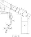
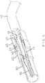
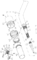
- a welding gun in accordance with the preferred embodiment of the present invention comprises a bending pipe 10, an insulating barrel 20 mounted on the bending pipe 10, a nozzle 30 mounted on the bending pipe 10, a connector 40 connected with the insulating barrel 20, and a cap 50 connected with the connector 40.
- the bending pipe 10 has an end provided with a mounting seat 11.
- a liner tube 88 (see FIG. 8 ) is mounted in the mounting seat 11.
- the liner tube 88 is made of rubber or plastic material.
- a spring “S” (see FIG. 8 ) is mounted on the liner tube 88 and disposed in the mounting seat 11.
- the spring "S” has an outer diameter slightly smaller than an inner diameter of the mounting seat 11.
- the mounting seat 11 has an exterior provided with an stepped edge 12, a groove 14 and an external thread 13.
- the groove 14 of the mounting seat 11 is defined between the stepped edge 12 and the external thread 13 and has a periphery provided with a plurality of flow channels 15 which extend radially.
- the mounting seat 11 has an interior provided with an internal thread 16.
- the flow channels 15 of the mounting seat 11 are connected to the interior of the mounting seat 11.
- the insulating barrel 20 is preferably made of insulation material, such as plastic material.
- the insulating barrel 20 is mounted on the mounting seat 11 of the bending pipe 10 and has an interior provided with a mounting hole 82, an air chamber 23 and an internal thread 83.
- the air chamber 23 of the insulating barrel 20 is defined between the mounting hole 82 and the internal thread 83 and connected to the flow channels 15 of the mounting seat 11.
- the mounting hole 82 of the insulating barrel 20 is mounted on the stepped edge 12 of the mounting seat 11 to form a closed state between the mounting hole 82 of the insulating barrel 20 and the stepped edge 12 of the mounting seat 11 to allow a welding gas to flow through the flow channels 15 of the mounting seat 11 into the air chamber 23 of the insulating barrel 20.
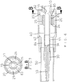
- the air chamber 23 of the insulating barrel 20 includes a plane 85 and a guiding wall 86 to evenly stabilize a pressure of the welding gas in the air chamber 23 of the insulating barrel 20.
- the internal thread 83 of the insulating barrel 20 is screwed onto the external thread 13 of the mounting seat 11.
- the insulating barrel 20 has a mediate portion provided with a recessed end face 24 which is provided with a plurality of guiding holes 25 to evenly distribute the welding gas.
- the guiding holes 25 of the insulating barrel 20 are connected to the air chamber 23 and correspond to the plane 85 of the air chamber 23.
- the insulating barrel 20 has an exterior provided with an external thread 26.
- the nozzle 30 has an exterior provided with an external thread 31 screwed into the internal thread 16 of the mounting seat 11.
- the nozzle 30 has a mediate portion provided with an outer rim 32 abutting the mounting seat 11.
- the nozzle 30 has an interior provided with an outlet port 33 to allow insertion of an electrode 60.
- the outlet port 33 of the nozzle 30 has an end provided with a conical hole 34 connected to the interior of the mounting seat 11.
- the connector 40 has a first end provided with a first inner thread 41 screwed onto the external thread 26 of the insulating barrel 20 and a second end provided with a second inner thread 43.
- the connector 40 has an interior provided with a conical guide face 42 and a restriction flow channel 84.
- the guide face 42 of the connector 40 corresponds to the guiding holes 25 of the insulating barrel 20 to guide and direct the welding gas toward a central position of the connector 40.
- the guide face 42 of the connector 40 is disposed between the restriction flow channel 84 and the guiding holes 25 of the insulating barrel 20.
- the restriction flow channel 84 of the connector 40 restricts the welding gas in the cap 50.
- the cap 50 has an end provided with an outer thread 51 screwed into the second inner thread 43 of the connector 40.
- the cap 50 covers the mounting seat 11 and the nozzle 30.
- the welding gas initially flows from the bending pipe 10 into the mounting seat 11. Then, the welding gas in the mounting seat 11 flows through the flow channels 15 of the mounting seat 11 into the air chamber 23 of the insulating barrel 20. At this time, the guiding wall 86 of the insulating barrel 20 stabilizes and evenly distributes the pressure of the welding gas in the air chamber 23 of the insulating barrel 20. Then, the welding gas flows through the guiding holes 25 of the insulating barrel 20 into the connector 40.
- the guide face 42 of the connector 40 corresponds to the guiding holes 25 of the insulating barrel 20 to guide and direct the welding gas toward the central position of the connector 40, while the restriction flow channel 84 of the connector 40 restricts the welding gas in the cap 50.
- the welding gas flows into the cap 50 and is injected outward from the cap 50.
- the welding gas covers and protects a welding zone of the electrode 60 to prevent from incurring oxidation and pollution.
- the welding gas stabilizes the welding operation to provide a safe welding process and to enhance the aesthetic quality of the welding spot.
- the welding gas is stabilized and regulated to save the energy and the amount of the welding gas.
- the pressure of the welding gas is stabilized and evenly distributed by the guiding wall 86 of the insulating barrel 20 so that the welding operation is performed safely, and the aesthetic quality of the welding spot is enhanced.
Landscapes
- Engineering & Computer Science (AREA)
- Physics & Mathematics (AREA)
- Plasma & Fusion (AREA)
- Mechanical Engineering (AREA)
- Resistance Welding (AREA)
Claims (3)
- Schweißpistole, aufweisend:ein gebogenes Rohr (10);ein isoliertes Rohr (20), das an dem gebogenen Rohr (10) angebracht ist;eine Düse (30), die an dem geborgenen Rohr (10) angebracht ist;ein Verbindungsstück (40), das mit der isolierten Rohr (20) verbunden ist; undeine Kappe (50), die mit dem Verbindungsstück (40) verbunden ist;wobei:das gebogene Rohr (10) ein Ende hat, das mit einem Montagesitz (11) versehen ist;ein Einsatzrohr (88) in dem Montagesitz (11) angebracht ist;eine Feder (S) am Einsatzrohr (88) angebracht ist;der Montagesitz (11) eine Außenseite hat, die mit einer gestuften Kante (12), einer Nut (14) und einem Außengewinde (13) versehen ist;die Nut des Montagesitzes (11) zwischen der gestuften Kante (12) und dem Außengewinde (13) definiert ist und einen Umfang aufweist, der mit einer Vielzahl von Strömungskanälen (15) versehen ist;der Montagesitz (11) einen Innenraum aufweist, der mit einem Innengewinde (16) versehen ist;das isolierte Rohr (20) einen Innenraum aufweist, der mit einer Befestigungsöffnung (82), einer Luftkammer (23) und einem Innengewinde (83) versehen ist;die Luftkammer (23) des isolierten Rohres (20) mit den Strömungskanälen (15) des Montagesitzes (11) verbunden ist;die Montageöffnung (82) des isolierten Rohres (20) an der gestuften Kante (12) des Montagesitzes (11) angebracht ist, um zu ermöglichen, dass ein Schweißgas durch die Strömungskanäle (15) des Montagesitzes (11) in die Luftkammer (23) des isolierten Rohres (20) strömt;das Innengewinde (16) des isolierten Rohres (20) auf das Außengewinde (13) des Montagesitzes (11) aufgeschraubt ist;das isolierte Rohr (20) einen Zwischenbereich aufweist, der mit einer zurückgesetzten Endfläche (24) versehen ist, die mit einer Mehrzahl von Führungsöffnungen (25) versehen ist, um das Schweißgas gleichmäßig zu verteilen;die Führungsöffnungen (25) des isolierten Rohres (20) mit der Luftkammer (23) verbunden sind und der Ebene der Luftkammer (23) entsprechen;das isolierte Rohr (20) eine Außenseite hat, die mit einem Außengewinde (26) versehen ist;die Düse (30) eine Außenseite hat, die mit einem Außengewinde (31) versehen ist, welches in das Innengewinde des Montagesitzes (11) geschraubt ist;die Düse (30) einen Innenraum aufweist, der mit einer Auslassöffnung (33) versehen ist, um das Einführen einer Elektrode (60) zu ermöglichen;das Verbindungsstück (40) ein erstes Ende, das mit einem ersten Innengewinde (41) versehen ist, welches auf das Außengewinde (13) des isolierten Rohres (20) geschraubt ist, und ein zweites Ende hat, das mit einem zweiten Innengewinde (43) versehen ist;die Abdeckung (50) ein Ende aufweist, das mit einem Außengewinde (51) versehen ist, welches in das zweite Innengewinde (43) des Verbindungsstücks (40) geschraubt ist; unddie Abdeckung (50) bedeckt den Montagesitz (11) und die Düse (30) abdeckt;dadurch gekennzeichnet, dassdie Luftkammer (23) des isolierten Rohres (20) eine Ebene (85) und eine Führungswand (86) aufweist, um einen Druck des Schweißgases gleichmäßig zu stabilisieren;das Verbindungsstück (40) einen Innenraum aufweist, der mit einer konischen Führungsfläche (42) und einem Drosselströmungskanal (84) versehen ist;die Führungsfläche (42) des Verbindungsstücks (40) den Führungsöffnungen (25) des isolierten Rohres (20) entspricht, um das Schweißgas zu einer zentralen Position des Verbindungsstücks (40) zu führen und zu leiten;der Drosselströmungskanal (84) des Verbindungsstücks (40) das Schweißgas in der Abdeckung (50) begrenzt;die Abdeckung (50) einen konstanten Durchmesser aufweist.
- Schweißpistole nach Anspruch 1, wobei die Auslassöffnung der Düse (30) ein Ende aufweist, das mit einer konischen Öffnung (34) versehen ist, die mit dem Inneren des Montagesitzes (11) verbunden ist.
- Schweißpistole nach Anspruch 1, wobei das isolierte Rohr (20) aus einem Isoliermaterial einschließlich Kunststoffmaterial hergestellt ist.
Priority Applications (1)
| Application Number | Priority Date | Filing Date | Title |
|---|---|---|---|
| EP16157556.8A EP3210708B1 (de) | 2016-02-26 | 2016-02-26 | Schweisszange mit gleichmässig verteiltem gasdruck |
Applications Claiming Priority (1)
| Application Number | Priority Date | Filing Date | Title |
|---|---|---|---|
| EP16157556.8A EP3210708B1 (de) | 2016-02-26 | 2016-02-26 | Schweisszange mit gleichmässig verteiltem gasdruck |
Publications (2)
| Publication Number | Publication Date |
|---|---|
| EP3210708A1 EP3210708A1 (de) | 2017-08-30 |
| EP3210708B1 true EP3210708B1 (de) | 2018-01-24 |
Family
ID=55451050
Family Applications (1)
| Application Number | Title | Priority Date | Filing Date |
|---|---|---|---|
| EP16157556.8A Not-in-force EP3210708B1 (de) | 2016-02-26 | 2016-02-26 | Schweisszange mit gleichmässig verteiltem gasdruck |
Country Status (1)
| Country | Link |
|---|---|
| EP (1) | EP3210708B1 (de) |
Families Citing this family (2)
| Publication number | Priority date | Publication date | Assignee | Title |
|---|---|---|---|---|
| TR201903790A2 (tr) * | 2019-03-13 | 2019-04-22 | Timark Makine Sanayi Ve Ticaret Anonim Sirketi | Kaynak pensesi̇ |
| CN120038404A (zh) * | 2025-04-24 | 2025-05-27 | 二重(德阳)重型装备有限公司 | 一种用于埋弧焊的焊接装置 |
Family Cites Families (4)
| Publication number | Priority date | Publication date | Assignee | Title |
|---|---|---|---|---|
| US3775584A (en) * | 1972-11-30 | 1973-11-27 | D Moerke | Welding gun |
| US5278392A (en) * | 1992-02-18 | 1994-01-11 | Tomkins Industries, Inc. | Self-cleaning nozzle for a gas welding torch |
| US6852950B2 (en) * | 2002-08-09 | 2005-02-08 | Illinois Tool Works Inc. | Welding gun having a removable nozzle end portion and method for operating same |
| WO2007030720A1 (en) * | 2005-09-11 | 2007-03-15 | Illinois Tool Works Inc. | Welding torch having nozzle assembly with independently removable components |
-
2016
- 2016-02-26 EP EP16157556.8A patent/EP3210708B1/de not_active Not-in-force
Non-Patent Citations (1)
| Title |
|---|
| None * |
Also Published As
| Publication number | Publication date |
|---|---|
| EP3210708A1 (de) | 2017-08-30 |
Similar Documents
| Publication | Publication Date | Title |
|---|---|---|
| EP3357626B1 (de) | Kontaktrohrhalterung zur verwendung mit einem schweisssystem | |
| EP3357625B1 (de) | Kontaktrohrhalterung zur verwendung mit einem schweisssystem | |
| US4590354A (en) | Plasma welding or cutting torch | |
| JP4200181B2 (ja) | スプレーガン | |
| US20170208866A1 (en) | Electronic cigarette | |
| US4682005A (en) | Plasma welding or cutting torch provided with a nozzle cartridge | |
| US10092972B2 (en) | Welding diffuser insert | |
| EP3068571B1 (de) | Düseneinsatz für eine lichtbogenschweissvorrichtung mit einem internen gasumleiter ; lichtbogenschweissvorrichtung mit einem solchen düseneinsatz | |
| EP2776202B1 (de) | Manuelle/robotische lichtbogen-schutzgasschweisspistole mit einem verbinder für einen verbindungsschlauch | |
| US9527155B2 (en) | Welding diffuser with debris removal | |
| EP3210708B1 (de) | Schweisszange mit gleichmässig verteiltem gasdruck | |
| CA2961150C (en) | Two-piece nozzle assembly for an arc welding apparatus | |
| KR102635796B1 (ko) | 환기형 플라즈마 절단 전극 및 그러한 전극을 이용하는 토치 | |
| US20140061337A1 (en) | Spray gun | |
| KR101364754B1 (ko) | 이산화탄소 용접토치용 교체식 노즐 | |
| US9630271B1 (en) | Welding gun with evenly distributed gas pressure | |
| EP2829799A1 (de) | Brennschneidspitze zur verhinderung von rückzündung | |
| US9358560B2 (en) | Spray gun | |
| JP7286306B2 (ja) | 溶接トーチ | |
| KR101837372B1 (ko) | 용접토치용 디퓨저 | |
| KR20150048020A (ko) | 수동가스절단기용 팁 | |
| CN211587114U (zh) | 一种应用于喷漆枪的喷嘴 | |
| KR101778769B1 (ko) | 노즐 일체형 토치헤드 및 이를 포함하는 용접장치 | |
| US20160165818A1 (en) | Coupler | |
| CN107477581B (zh) | 一种割咀结构 |
Legal Events
| Date | Code | Title | Description |
|---|---|---|---|
| PUAI | Public reference made under article 153(3) epc to a published international application that has entered the european phase |
Free format text: ORIGINAL CODE: 0009012 |
|
| 17P | Request for examination filed |
Effective date: 20161216 |
|
| AK | Designated contracting states |
Kind code of ref document: A1 Designated state(s): AL AT BE BG CH CY CZ DE DK EE ES FI FR GB GR HR HU IE IS IT LI LT LU LV MC MK MT NL NO PL PT RO RS SE SI SK SM TR |
|
| AX | Request for extension of the european patent |
Extension state: BA ME |
|
| GRAP | Despatch of communication of intention to grant a patent |
Free format text: ORIGINAL CODE: EPIDOSNIGR1 |
|
| INTG | Intention to grant announced |
Effective date: 20171017 |
|
| GRAS | Grant fee paid |
Free format text: ORIGINAL CODE: EPIDOSNIGR3 |
|
| GRAA | (expected) grant |
Free format text: ORIGINAL CODE: 0009210 |
|
| AK | Designated contracting states |
Kind code of ref document: B1 Designated state(s): AL AT BE BG CH CY CZ DE DK EE ES FI FR GB GR HR HU IE IS IT LI LT LU LV MC MK MT NL NO PL PT RO RS SE SI SK SM TR |
|
| REG | Reference to a national code |
Ref country code: GB Ref legal event code: FG4D |
|
| REG | Reference to a national code |
Ref country code: FR Ref legal event code: PLFP Year of fee payment: 3 |
|
| REG | Reference to a national code |
Ref country code: CH Ref legal event code: EP |
|
| REG | Reference to a national code |
Ref country code: AT Ref legal event code: REF Ref document number: 965511 Country of ref document: AT Kind code of ref document: T Effective date: 20180215 |
|
| REG | Reference to a national code |
Ref country code: IE Ref legal event code: FG4D |
|
| REG | Reference to a national code |
Ref country code: DE Ref legal event code: R096 Ref document number: 602016001416 Country of ref document: DE |
|
| REG | Reference to a national code |
Ref country code: NL Ref legal event code: FP |
|
| REG | Reference to a national code |
Ref country code: LT Ref legal event code: MG4D |
|
| REG | Reference to a national code |
Ref country code: AT Ref legal event code: MK05 Ref document number: 965511 Country of ref document: AT Kind code of ref document: T Effective date: 20180124 |
|
| PG25 | Lapsed in a contracting state [announced via postgrant information from national office to epo] |
Ref country code: NO Free format text: LAPSE BECAUSE OF FAILURE TO SUBMIT A TRANSLATION OF THE DESCRIPTION OR TO PAY THE FEE WITHIN THE PRESCRIBED TIME-LIMIT Effective date: 20180424 Ref country code: FI Free format text: LAPSE BECAUSE OF FAILURE TO SUBMIT A TRANSLATION OF THE DESCRIPTION OR TO PAY THE FEE WITHIN THE PRESCRIBED TIME-LIMIT Effective date: 20180124 Ref country code: LT Free format text: LAPSE BECAUSE OF FAILURE TO SUBMIT A TRANSLATION OF THE DESCRIPTION OR TO PAY THE FEE WITHIN THE PRESCRIBED TIME-LIMIT Effective date: 20180124 Ref country code: CY Free format text: LAPSE BECAUSE OF FAILURE TO SUBMIT A TRANSLATION OF THE DESCRIPTION OR TO PAY THE FEE WITHIN THE PRESCRIBED TIME-LIMIT Effective date: 20180124 Ref country code: HR Free format text: LAPSE BECAUSE OF FAILURE TO SUBMIT A TRANSLATION OF THE DESCRIPTION OR TO PAY THE FEE WITHIN THE PRESCRIBED TIME-LIMIT Effective date: 20180124 |
|
| PG25 | Lapsed in a contracting state [announced via postgrant information from national office to epo] |
Ref country code: RS Free format text: LAPSE BECAUSE OF FAILURE TO SUBMIT A TRANSLATION OF THE DESCRIPTION OR TO PAY THE FEE WITHIN THE PRESCRIBED TIME-LIMIT Effective date: 20180124 Ref country code: PL Free format text: LAPSE BECAUSE OF FAILURE TO SUBMIT A TRANSLATION OF THE DESCRIPTION OR TO PAY THE FEE WITHIN THE PRESCRIBED TIME-LIMIT Effective date: 20180124 Ref country code: BG Free format text: LAPSE BECAUSE OF FAILURE TO SUBMIT A TRANSLATION OF THE DESCRIPTION OR TO PAY THE FEE WITHIN THE PRESCRIBED TIME-LIMIT Effective date: 20180424 Ref country code: AT Free format text: LAPSE BECAUSE OF FAILURE TO SUBMIT A TRANSLATION OF THE DESCRIPTION OR TO PAY THE FEE WITHIN THE PRESCRIBED TIME-LIMIT Effective date: 20180124 Ref country code: IS Free format text: LAPSE BECAUSE OF FAILURE TO SUBMIT A TRANSLATION OF THE DESCRIPTION OR TO PAY THE FEE WITHIN THE PRESCRIBED TIME-LIMIT Effective date: 20180524 Ref country code: LV Free format text: LAPSE BECAUSE OF FAILURE TO SUBMIT A TRANSLATION OF THE DESCRIPTION OR TO PAY THE FEE WITHIN THE PRESCRIBED TIME-LIMIT Effective date: 20180124 Ref country code: SE Free format text: LAPSE BECAUSE OF FAILURE TO SUBMIT A TRANSLATION OF THE DESCRIPTION OR TO PAY THE FEE WITHIN THE PRESCRIBED TIME-LIMIT Effective date: 20180124 Ref country code: GR Free format text: LAPSE BECAUSE OF FAILURE TO SUBMIT A TRANSLATION OF THE DESCRIPTION OR TO PAY THE FEE WITHIN THE PRESCRIBED TIME-LIMIT Effective date: 20180425 |
|
| REG | Reference to a national code |
Ref country code: DE Ref legal event code: R097 Ref document number: 602016001416 Country of ref document: DE |
|
| PG25 | Lapsed in a contracting state [announced via postgrant information from national office to epo] |
Ref country code: MC Free format text: LAPSE BECAUSE OF FAILURE TO SUBMIT A TRANSLATION OF THE DESCRIPTION OR TO PAY THE FEE WITHIN THE PRESCRIBED TIME-LIMIT Effective date: 20180124 Ref country code: RO Free format text: LAPSE BECAUSE OF FAILURE TO SUBMIT A TRANSLATION OF THE DESCRIPTION OR TO PAY THE FEE WITHIN THE PRESCRIBED TIME-LIMIT Effective date: 20180124 Ref country code: EE Free format text: LAPSE BECAUSE OF FAILURE TO SUBMIT A TRANSLATION OF THE DESCRIPTION OR TO PAY THE FEE WITHIN THE PRESCRIBED TIME-LIMIT Effective date: 20180124 Ref country code: AL Free format text: LAPSE BECAUSE OF FAILURE TO SUBMIT A TRANSLATION OF THE DESCRIPTION OR TO PAY THE FEE WITHIN THE PRESCRIBED TIME-LIMIT Effective date: 20180124 |
|
| REG | Reference to a national code |
Ref country code: IE Ref legal event code: MM4A |
|
| REG | Reference to a national code |
Ref country code: BE Ref legal event code: MM Effective date: 20180228 |
|
| PG25 | Lapsed in a contracting state [announced via postgrant information from national office to epo] |
Ref country code: SK Free format text: LAPSE BECAUSE OF FAILURE TO SUBMIT A TRANSLATION OF THE DESCRIPTION OR TO PAY THE FEE WITHIN THE PRESCRIBED TIME-LIMIT Effective date: 20180124 Ref country code: CZ Free format text: LAPSE BECAUSE OF FAILURE TO SUBMIT A TRANSLATION OF THE DESCRIPTION OR TO PAY THE FEE WITHIN THE PRESCRIBED TIME-LIMIT Effective date: 20180124 Ref country code: LU Free format text: LAPSE BECAUSE OF NON-PAYMENT OF DUE FEES Effective date: 20180226 Ref country code: SM Free format text: LAPSE BECAUSE OF FAILURE TO SUBMIT A TRANSLATION OF THE DESCRIPTION OR TO PAY THE FEE WITHIN THE PRESCRIBED TIME-LIMIT Effective date: 20180124 Ref country code: DK Free format text: LAPSE BECAUSE OF FAILURE TO SUBMIT A TRANSLATION OF THE DESCRIPTION OR TO PAY THE FEE WITHIN THE PRESCRIBED TIME-LIMIT Effective date: 20180124 |
|
| PLBE | No opposition filed within time limit |
Free format text: ORIGINAL CODE: 0009261 |
|
| STAA | Information on the status of an ep patent application or granted ep patent |
Free format text: STATUS: NO OPPOSITION FILED WITHIN TIME LIMIT |
|
| 26N | No opposition filed |
Effective date: 20181025 |
|
| PG25 | Lapsed in a contracting state [announced via postgrant information from national office to epo] |
Ref country code: IE Free format text: LAPSE BECAUSE OF NON-PAYMENT OF DUE FEES Effective date: 20180226 |
|
| PG25 | Lapsed in a contracting state [announced via postgrant information from national office to epo] |
Ref country code: BE Free format text: LAPSE BECAUSE OF NON-PAYMENT OF DUE FEES Effective date: 20180228 |
|
| PGFP | Annual fee paid to national office [announced via postgrant information from national office to epo] |
Ref country code: IT Payment date: 20190228 Year of fee payment: 4 Ref country code: FR Payment date: 20190117 Year of fee payment: 4 |
|
| PG25 | Lapsed in a contracting state [announced via postgrant information from national office to epo] |
Ref country code: ES Free format text: LAPSE BECAUSE OF FAILURE TO SUBMIT A TRANSLATION OF THE DESCRIPTION OR TO PAY THE FEE WITHIN THE PRESCRIBED TIME-LIMIT Effective date: 20180124 |
|
| REG | Reference to a national code |
Ref country code: CH Ref legal event code: PL |
|
| REG | Reference to a national code |
Ref country code: NL Ref legal event code: MM Effective date: 20190301 |
|
| PG25 | Lapsed in a contracting state [announced via postgrant information from national office to epo] |
Ref country code: CH Free format text: LAPSE BECAUSE OF NON-PAYMENT OF DUE FEES Effective date: 20190228 Ref country code: LI Free format text: LAPSE BECAUSE OF NON-PAYMENT OF DUE FEES Effective date: 20190228 |
|
| PG25 | Lapsed in a contracting state [announced via postgrant information from national office to epo] |
Ref country code: MT Free format text: LAPSE BECAUSE OF NON-PAYMENT OF DUE FEES Effective date: 20180226 Ref country code: NL Free format text: LAPSE BECAUSE OF NON-PAYMENT OF DUE FEES Effective date: 20190301 |
|
| PG25 | Lapsed in a contracting state [announced via postgrant information from national office to epo] |
Ref country code: TR Free format text: LAPSE BECAUSE OF FAILURE TO SUBMIT A TRANSLATION OF THE DESCRIPTION OR TO PAY THE FEE WITHIN THE PRESCRIBED TIME-LIMIT Effective date: 20180124 |
|
| PGFP | Annual fee paid to national office [announced via postgrant information from national office to epo] |
Ref country code: DE Payment date: 20200225 Year of fee payment: 5 |
|
| PG25 | Lapsed in a contracting state [announced via postgrant information from national office to epo] |
Ref country code: PT Free format text: LAPSE BECAUSE OF FAILURE TO SUBMIT A TRANSLATION OF THE DESCRIPTION OR TO PAY THE FEE WITHIN THE PRESCRIBED TIME-LIMIT Effective date: 20180124 |
|
| PG25 | Lapsed in a contracting state [announced via postgrant information from national office to epo] |
Ref country code: HU Free format text: LAPSE BECAUSE OF FAILURE TO SUBMIT A TRANSLATION OF THE DESCRIPTION OR TO PAY THE FEE WITHIN THE PRESCRIBED TIME-LIMIT; INVALID AB INITIO Effective date: 20160226 Ref country code: MK Free format text: LAPSE BECAUSE OF NON-PAYMENT OF DUE FEES Effective date: 20180124 |
|
| GBPC | Gb: european patent ceased through non-payment of renewal fee |
Effective date: 20200226 |
|
| PG25 | Lapsed in a contracting state [announced via postgrant information from national office to epo] |
Ref country code: SI Free format text: LAPSE BECAUSE OF NON-PAYMENT OF DUE FEES Effective date: 20180226 |
|
| PG25 | Lapsed in a contracting state [announced via postgrant information from national office to epo] |
Ref country code: GB Free format text: LAPSE BECAUSE OF NON-PAYMENT OF DUE FEES Effective date: 20200226 Ref country code: FR Free format text: LAPSE BECAUSE OF NON-PAYMENT OF DUE FEES Effective date: 20200229 |
|
| REG | Reference to a national code |
Ref country code: DE Ref legal event code: R119 Ref document number: 602016001416 Country of ref document: DE |
|
| PG25 | Lapsed in a contracting state [announced via postgrant information from national office to epo] |
Ref country code: IT Free format text: LAPSE BECAUSE OF NON-PAYMENT OF DUE FEES Effective date: 20200226 |
|
| PG25 | Lapsed in a contracting state [announced via postgrant information from national office to epo] |
Ref country code: DE Free format text: LAPSE BECAUSE OF NON-PAYMENT OF DUE FEES Effective date: 20210901 |