EP3210897A1 - Aufbewahrungsanordnung und zugehöriges verfahren - Google Patents
Aufbewahrungsanordnung und zugehöriges verfahren Download PDFInfo
- Publication number
- EP3210897A1 EP3210897A1 EP16156818.3A EP16156818A EP3210897A1 EP 3210897 A1 EP3210897 A1 EP 3210897A1 EP 16156818 A EP16156818 A EP 16156818A EP 3210897 A1 EP3210897 A1 EP 3210897A1
- Authority
- EP
- European Patent Office
- Prior art keywords
- pressure
- storage chamber
- storage
- pressure device
- air
- Prior art date
- Legal status (The legal status is an assumption and is not a legal conclusion. Google has not performed a legal analysis and makes no representation as to the accuracy of the status listed.)
- Withdrawn
Links
- 238000000034 method Methods 0.000 title claims abstract description 19
- 238000004891 communication Methods 0.000 claims abstract description 3
- 238000012856 packing Methods 0.000 claims description 90
- 239000000203 mixture Substances 0.000 claims description 37
- 230000009467 reduction Effects 0.000 claims description 9
- 230000003416 augmentation Effects 0.000 claims description 6
- 239000003570 air Substances 0.000 description 82
- 239000007789 gas Substances 0.000 description 74
- 238000005057 refrigeration Methods 0.000 description 17
- 239000011111 cardboard Substances 0.000 description 15
- 238000001816 cooling Methods 0.000 description 11
- VGGSQFUCUMXWEO-UHFFFAOYSA-N Ethene Chemical compound C=C VGGSQFUCUMXWEO-UHFFFAOYSA-N 0.000 description 10
- 239000005977 Ethylene Substances 0.000 description 10
- 235000013399 edible fruits Nutrition 0.000 description 7
- CURLTUGMZLYLDI-UHFFFAOYSA-N Carbon dioxide Chemical compound O=C=O CURLTUGMZLYLDI-UHFFFAOYSA-N 0.000 description 6
- 230000035699 permeability Effects 0.000 description 5
- IJGRMHOSHXDMSA-UHFFFAOYSA-N Atomic nitrogen Chemical compound N#N IJGRMHOSHXDMSA-UHFFFAOYSA-N 0.000 description 4
- 230000003247 decreasing effect Effects 0.000 description 4
- 230000000694 effects Effects 0.000 description 4
- 235000012055 fruits and vegetables Nutrition 0.000 description 4
- 240000004160 Capsicum annuum Species 0.000 description 3
- 235000008534 Capsicum annuum var annuum Nutrition 0.000 description 3
- 241000196324 Embryophyta Species 0.000 description 3
- 239000012080 ambient air Substances 0.000 description 3
- QVGXLLKOCUKJST-UHFFFAOYSA-N atomic oxygen Chemical compound [O] QVGXLLKOCUKJST-UHFFFAOYSA-N 0.000 description 3
- 230000008901 benefit Effects 0.000 description 3
- 239000001511 capsicum annuum Substances 0.000 description 3
- 229910002092 carbon dioxide Inorganic materials 0.000 description 3
- 239000001569 carbon dioxide Substances 0.000 description 3
- 238000011161 development Methods 0.000 description 3
- 239000001301 oxygen Substances 0.000 description 3
- 229910052760 oxygen Inorganic materials 0.000 description 3
- 230000005070 ripening Effects 0.000 description 3
- 241000234295 Musa Species 0.000 description 2
- 238000013459 approach Methods 0.000 description 2
- 230000003190 augmentative effect Effects 0.000 description 2
- 235000021015 bananas Nutrition 0.000 description 2
- 230000008859 change Effects 0.000 description 2
- 230000001143 conditioned effect Effects 0.000 description 2
- 235000013365 dairy product Nutrition 0.000 description 2
- 238000010586 diagram Methods 0.000 description 2
- 238000010438 heat treatment Methods 0.000 description 2
- 239000000463 material Substances 0.000 description 2
- JCXJVPUVTGWSNB-UHFFFAOYSA-N nitrogen dioxide Inorganic materials O=[N]=O JCXJVPUVTGWSNB-UHFFFAOYSA-N 0.000 description 2
- 230000008569 process Effects 0.000 description 2
- 230000000630 rising effect Effects 0.000 description 2
- 241000736542 Awaous banana Species 0.000 description 1
- 235000007688 Lycopersicon esculentum Nutrition 0.000 description 1
- 244000141359 Malus pumila Species 0.000 description 1
- 240000003768 Solanum lycopersicum Species 0.000 description 1
- 230000001133 acceleration Effects 0.000 description 1
- 235000021016 apples Nutrition 0.000 description 1
- 230000000712 assembly Effects 0.000 description 1
- 238000000429 assembly Methods 0.000 description 1
- 238000004140 cleaning Methods 0.000 description 1
- 238000004590 computer program Methods 0.000 description 1
- 239000000470 constituent Substances 0.000 description 1
- 238000005336 cracking Methods 0.000 description 1
- 230000001627 detrimental effect Effects 0.000 description 1
- 230000007774 longterm Effects 0.000 description 1
- 235000013372 meat Nutrition 0.000 description 1
- 229910052757 nitrogen Inorganic materials 0.000 description 1
- 210000000056 organ Anatomy 0.000 description 1
Images


Classifications
-
- B—PERFORMING OPERATIONS; TRANSPORTING
- B65—CONVEYING; PACKING; STORING; HANDLING THIN OR FILAMENTARY MATERIAL
- B65B—MACHINES, APPARATUS OR DEVICES FOR, OR METHODS OF, PACKAGING ARTICLES OR MATERIALS; UNPACKING
- B65B55/00—Preserving, protecting or purifying packages or package contents in association with packaging
-
- A—HUMAN NECESSITIES
- A23—FOODS OR FOODSTUFFS; TREATMENT THEREOF, NOT COVERED BY OTHER CLASSES
- A23B—PRESERVATION OF FOODS, FOODSTUFFS OR NON-ALCOHOLIC BEVERAGES; CHEMICAL RIPENING OF FRUIT OR VEGETABLES
- A23B7/00—Preservation of fruit or vegetables; Chemical ripening of fruit or vegetables
- A23B7/04—Freezing; Subsequent thawing; Cooling
- A23B7/0425—Materials not being transported through or in the apparatus, with or without shaping, e.g. in the form of powders, granules or flakes
-
- A—HUMAN NECESSITIES
- A23—FOODS OR FOODSTUFFS; TREATMENT THEREOF, NOT COVERED BY OTHER CLASSES
- A23B—PRESERVATION OF FOODS, FOODSTUFFS OR NON-ALCOHOLIC BEVERAGES; CHEMICAL RIPENING OF FRUIT OR VEGETABLES
- A23B7/00—Preservation of fruit or vegetables; Chemical ripening of fruit or vegetables
- A23B7/14—Preserving or ripening with chemicals not covered by group A23B7/08 or A23B7/10
- A23B7/144—Preserving or ripening with chemicals not covered by group A23B7/08 or A23B7/10 in the form of gases, e.g. fumigation; Compositions or apparatus therefor
- A23B7/152—Preserving or ripening with chemicals not covered by group A23B7/08 or A23B7/10 in the form of gases, e.g. fumigation; Compositions or apparatus therefor in a controlled atmosphere comprising other gases in addition to CO2, N2, O2 or H2O ; Elimination of such other gases
-
- F—MECHANICAL ENGINEERING; LIGHTING; HEATING; WEAPONS; BLASTING
- F25—REFRIGERATION OR COOLING; COMBINED HEATING AND REFRIGERATION SYSTEMS; HEAT PUMP SYSTEMS; MANUFACTURE OR STORAGE OF ICE; LIQUEFACTION SOLIDIFICATION OF GASES
- F25D—REFRIGERATORS; COLD ROOMS; ICE-BOXES; COOLING OR FREEZING APPARATUS NOT OTHERWISE PROVIDED FOR
- F25D17/00—Arrangements for circulating cooling fluids; Arrangements for circulating gas, e.g. air, within refrigerated spaces
- F25D17/04—Arrangements for circulating cooling fluids; Arrangements for circulating gas, e.g. air, within refrigerated spaces for circulating air, e.g. by convection
- F25D17/042—Air treating means within refrigerated spaces
-
- F—MECHANICAL ENGINEERING; LIGHTING; HEATING; WEAPONS; BLASTING
- F25—REFRIGERATION OR COOLING; COMBINED HEATING AND REFRIGERATION SYSTEMS; HEAT PUMP SYSTEMS; MANUFACTURE OR STORAGE OF ICE; LIQUEFACTION SOLIDIFICATION OF GASES
- F25D—REFRIGERATORS; COLD ROOMS; ICE-BOXES; COOLING OR FREEZING APPARATUS NOT OTHERWISE PROVIDED FOR
- F25D2317/00—Details or arrangements for circulating cooling fluids; Details or arrangements for circulating gas, e.g. air, within refrigerated spaces, not provided for in other groups of this subclass
- F25D2317/04—Treating air flowing to refrigeration compartments
- F25D2317/043—Treating air flowing to refrigeration compartments by creating a vacuum in a storage compartment
Definitions
- the present invention relates to a storage assembly configured to control, and a method of controlling, climate conditions inside permeable packing.
- controlled climate conditions can involve e.g. temperature and gas composition within such permeable packing.
- the invention also relates to an associated method.
- Storage assemblies are essential for transportation of many types of goods. Such types are typical goods that should be stored within a certain temperature range, or with a certain gas composition.
- One example is the storage of fruits and vegetables, stored in cardboard packing.
- the climate within the packing will affect the quality of the fruits and vegetables after storage. Consequently, one seeks to control the climate within the packing.
- Other goods affected by climate within the packing includes, inter alia, flowers and other plants, dairy products, meats, and other cooled or even frozen goods.
- a typical scenario may be when transferring dairy products from a factory to a refrigerated transport vehicle on a warm summer day.
- patent publication GB1426917 discloses a variety of combinations of reduced pressures, temperatures and humidity for a variety of goods, such as apples, cut flowers, and tomatoes.
- a reduced pressure is used for many goods.
- a low air / gas pressure reduces the convection, and may increase the time for cooling the goods inside packings.
- climate can relate to parameters as temperature and gas composition within the packings.
- Some goods such as fruits, produce gases during storage, which affect the quality of the goods.
- a well-known example is fruit that produces ethylene gas.
- the ethylene gas accelerates ripening of the fruits. Consequently, it is often a desire to remove the ethylene gas from the space within the packing, in order to avoid the said acceleration of ripening.
- Such gas removal be it ethylene or another gas, is another object of the present invention.
- Some goods even produce heat during storage.
- the temperature within a packing that contains goods has been equalized to the same temperature as in the storage chamber in which the packing is stored, the temperature within the packing may rise.
- Such temperature rise may be the result of decay of plant material (e.g. fruits and vegetables), a process which produces heat.
- a storage assembly comprising a storage chamber, a pressure device in communication with the storage chamber, and a pressure device control unit controlling the pressure device.
- the pressure device control unit is configured to control the pressure device to sequentially amend the pressure within the storage chamber according to a reciprocating pressure pattern.
- the pressure device control unit is configured to control the pressure device in the said manner, within a predetermined frequency range.
- a frequency range will depend on the goods in the packings that are stored in the storage chamber. For example, if small packings with a high degree of permeability are used, the frequency with which the pressure is reciprocated, can be relatively large. This may for instance be the case with boxes that are perforated in order to vent the inside of the boxes. On the other hand, if large packings are used, which have a low degree of permeability, the pressure should be reciprocated with a lower frequency. In this manner, one will give the needed time for gas to flow into and out of the packings, typically through small openings in the packings.
- a fragile packing with low permeability may be destroyed by a rapid pressure variation (pressure rise or pressure fall), since an excessive pressure drop and consequently an excessive, detrimental force may arise on the walls of the packing.
- a rapid pressure drop in the ambience of a paprika may result in the paprika cracking open, since the paprika itself is filled with air / gas.
- reciprocating pressure pattern is meant a pressure which is succeedingly rising and sinking.
- the reciprocating pressure pattern within the storage chamber is a pressure inside the storage chamber which is made to fluctuate up and down.
- the derivative of the pressure value in the time domain will repeatedly change between positive and negative values. Indeed, the derivative may also remain zero for some periods (constant pressure).
- the storage chamber will have a closable door, hatch or other closable member, making it possible to transport goods into and out of the storage chamber when the door is open.
- the storage chamber should advantageously be substantially air tight in order to obtain the reciprocating pressure pattern.
- the door should be closed when reciprocating the pressure in the storage chamber.
- the pressure device control unit is configured to control the operation of the pressure device, it should be clear that other control units may control components which also may affect the pressure in the storage chamber.
- a valve can be controlled by a valve control unit, wherein the valve is used for increasing or decreasing the pressure, by letting gas (e.g. air) into or out of the storage chamber.
- gas e.g. air
- the pressure device control unit may control the pressure device as well as other components that affect the pressure.
- the pressure device may be configured to reduce pressure in the storage chamber. In other embodiments, the pressure device may be configured to increase the pressure. The pressure device may also be configured to both reduce and increase the storage chamber pressure. Alternatively, one may have two pressure devices, wherein one is configured to increase pressure, while the other is configured to reduce pressure.
- the pressure device control unit can comprise or connect to electronically stored or electronically readable pressure control instructions, according to which the pressure device control unit is configured to operate the pressure device.
- the reciprocating pressure pattern can include at least five succeeding steps of pressure reductions and pressure augmentations. In some embodiments, one will commence with a pressure reduction, followed by pressure rise, and repeat this several times. In other embodiments, one may commence with a pressure augmentation, followed by a pressure drop.
- the pressure device control unit can be configured to control the pressure device in such manner that the reciprocating pressure pattern is within a predetermined frequency range of 0,0006 Hz to 10 Hz.
- This frequency range corresponds to a cycle time ranging from 0,1 seconds to about 28 minutes.
- Other embodiments can however include other frequency ranges, including both higher and lower frequencies than indicated in the frequency range above.
- some reciprocating pressure patterns may have periods with substantially constant pressure, interposed between pressure variations.
- the storage assembly according to the invention can be installed on a transport vehicle.
- a transport vehicle such as a refrigerated trailer / truck. It may also be retrofitted to existing vehicles or transport containers, typical cooled containers.
- the pressure control instructions can include a start-up phase and a storage phase, wherein the start-up phase includes larger pressure variations and/or higher frequency of the pressure variations, than the storage phase does.
- a pressure variation is defined as the pressure difference between the pressure value at the start and the pressure value at the end of a pressure rise or pressure drop.
- the storage assembly can comprise a storage chamber condition manipulation means, including at least one of a temperature device and a gas composition device.
- a temperature device can typically be a cooling device, configured to maintain a relatively (compared to the climate outside of the storage chamber) cold temperature in the storage chamber. It may however also be a heating device, configured to maintain a relatively warm temperature in the storage chamber.
- a gas composition device can typically be a device configured to adjust the composition of gases in the storage chamber.
- the gas composition device may for instance be an air humidity device, which can be controlled to adjust the humidity inside the storage chamber (i.e. humidity of the air inside the storage chamber).
- the gas composition device can however also be of a type configured to add and/or to remove other specific gases or specific types of gases.
- the storage assembly may still be used to evacuate certain undesirable gases from the inside of packings, such as cardboard boxes.
- packings such as cardboard boxes.
- Such an undesirable gas can for instance be ethylene produced by fruits stored in cardboard boxes.
- a storage chamber condition manipulation means one may increase control of the storage chamber climate, and consequently the climate within the packings.
- the storage assembly according to the invention may include an evacuated gas storage.
- the pressure device can then, in some embodiments, be arranged in a flow path between the storage chamber and the evacuated gas storage.
- a re-entry flow path can exist between the evacuated gas storage and the storage chamber.
- the flow path between the storage chamber and the evacuated gas storage is the same as the re-entry flow path.
- a method of adjusting the climate of a packing space inside permeable packing which is stored in a storage chamber. The method includes the steps of
- the pressure is reciprocated within a predetermined frequency range.
- the frequency of the pressure fluctuations should be adapted to the packings and goods stored in the storage chamber.
- step b) comprises at least five succeeding steps of pressure reductions and pressure augmentations.
- step b) can include at least five pressure fluctuations.
- Step b) can also be performed, at least partly, by means of a pressure device communicating with the storage chamber.
- Step b) can then include controlling the pressure device with a pressure device control unit, which operates according to a set of predetermined, stored pressure control instructions.
- the term "at least partly” shall mean that also other components also may be used for amending the pressure.
- An example of such another component is a valve, which may be opened, thereby letting air or gas flow into or out of the storage chamber (and then the valve can be closed).
- the storage chamber can be carried by a wheeled vehicle, wherein step b) is performed while the vehicle is moving.
- the storage chamber may be on another transport means, such as a ship.
- the storage chamber will be inside a refrigerated container.
- a refrigerated container is to be understood as any type of arrangement for storing and refrigerating goods, such as a refrigerated transportation container or reefer, a cold storage, a refrigerated space or the like.
- Many embodiments of the invention is particularly, but not exclusively, advantageous for cooling goods in packing, such as goods inside card board boxes or other containers.
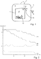
- Fig. 1 is a schematic illustration for the purpose of explaining the function of the invention.
- a permeable packing such as a cardboard box 1
- the storage chamber 3 is a substantially airtight container 5 having container walls 7.
- the container 5 is also provided with a door (not shown in Fig. 1 ), so that one can move items, such as the cardboard box 1, into and out of the storage chamber 3.
- a pressure device 9 configured to alter the internal pressure in the storage chamber 3. I.e. it can lower and raise the internal pressure.
- FIG. 1 Inside the packing, here in the form of the cardboard box 1, there is a packing space 11.
- a box opening 13 is shown in Fig. 1 , to illustrate the permeability of the cardboard box 1.
- the goods 15 stored inside the packing space 11 of the cardboard box 1 are fruits, here represented by bananas.
- the cardboard box 1, as well as the goods 15 are relatively warm, for instance a temperature of 25 °C. It is further assumed that the temperature inside the storage chamber 3 is colder, e.g. 10 °C, and that the goods 15 shall be cooled down to the temperature inside the storage chamber.
- the permeability of the packing 1 may not be in the form of a defined opening 13 as illustrated in Fig. 1 . Rather, some packings 1 may be provided with perforations in the packing walls. Other packings 1 may be more closed, but still not be completely air tight and still permeable. Yet other packings 1 may have significantly other shapes, for instance in the form of permeable and flexible bags.
- Fig. 2 depicts experimental results from a refrigeration process with and without the use of the present invention. The results show that the invention is effective for cooling goods arranged in permeable packing.
- the second upper most temperature curve 20a shows the development in temperature inside a packing 1 being refrigerated using the storage assembly and method according to the invention.
- the dotted line temperature curve 20b shows the temperature inside the storage chamber 3 of the same storage assembly.
- the top temperature curve 21 a shows the development in temperature inside a packing or box being refrigerated using a conventional storage assembly.
- the bottom dotted line temperature curve 21 b shows the development in the ambient temperature inside the storage space of the conventional storage assembly. In the conventional assembly, the air pressure within the storage chamber remained constant.
- the temperature 20a approaches the storage chamber temperature 20b significantly faster that the temperature 21 a approaches the storage chamber temperature 21 b of the conventional assembly.
- the temperature inside a packing 1 refrigerated using the inventive storage assembly and method reaches the approximate temperature of the storage chamber 3.
- the difference between packing temperature 21 a and storage chamber temperature 21 b is still significant after 30 minutes of cooling.
- the refrigeration method and assembly according to the invention is thus effective for cooling goods arranged in permeable packing.
- Fig. 3 is a schematic illustration of a storage assembly 10 according to the invention.
- the container 5 has a closable door 17 through which packings 1 with goods 15 can be transported into and out of the storage chamber 3.
- the pressure device 9 is an arrangement which can be controlled to lower and raise the air (gas) pressure within the container 5, i.e. within the storage chamber 3.
- a pressure device control unit 19 connects to or is integrated with the pressure device 9.
- the pressure device control unit 19 is adapted to control the function of the pressure device 9. I.e. the control unit 19 can actuate the pressure device in such manner that the pressure device 9 raises the pressure and/or lowers the pressure in the storage chamber 3.
- the pressure device 9 can be configured to merely evacuate the storage chamber 3, thereby lowering its pressure, without being able to elevate the pressure.
- a valve which can let air back into the storage chamber 3 when the pressure shall rise.
- the pressure device 9 can be configured to augment the pressure in the storage chamber 3, without being able to lower the pressure.
- a valve can be operated, however in order to reduce the pressure.
- the pressure device 9 can be configured both to reduce and to elevate the storage chamber pressure.
- the pressure device control unit 19 comprises pressure control instructions 23.
- the pressure control instructions 23 are in this embodiment a set of computer readable instructions which governs the output of the pressure control unit 19, and hence the operation of the pressure device 9.
- the pressure control instructions 23 can be a computer program, readable by a computer such as a PLC (programmable logic controller). It may also be stored as an electric circuit. Moreover, the pressure control instructions 23 can, instead of being stored in the pressure device control unit 19 itself, be stored elsewhere, however with connection to the pressure device control unit 19.
- a computer such as a PLC (programmable logic controller)
- PLC programmable logic controller
- the storage assembly 10 also comprises a temperature device 25.
- the temperature device 25 is configured to maintain a predetermined temperature within the storage chamber 3.
- the temperature device 25 will be in the form of a refrigeration unit, adapted to maintain a relatively cold temperature in the storage chamber 3, compared to the temperature outside the container 5.
- the function and constructive elements of the temperature device 25 will not be described in detail herein, since refrigeration units as well as heating devices are assumed to be well known to the person skilled in the art.
- the storage assembly 10 depicted in Fig. 3 further comprises a gas composition device 27.
- a gas composition device 27 As discussed above, for some goods, such as fruits and vegetables, the gas mixture surrounding the goods will affect the goods.
- the gas composition device 27 is adapted for adjusting the composition of gases in the storage chamber.
- the gas composition device can be used for introducing a mixture of oxygen, nitrogen and or carbon dioxide into the storage chamber 3.
- the mixture of gasses may be adjusted according to the type of goods stored. Some goods may benefit from air inside the storage space with a high or lower content of a specific type of gas.
- the gas composition device 27 can also be configured to adjust the humidity inside the storage chamber 3.
- temperature controlled air e.g. cooled air
- a gas composition controlled air composition for instance containing a mixture of oxygen, nitrogen and/or carbon dioxide may be introduced into the storage chamber 3, by the gas composition device 27.
- Air (gas) removed from the storage chamber 3 during evacuation may also be cleaned and re-introduced into the storage space to increase the pressure.
- pressure variations within the storage chamber 3 can be accomplished by amending the volume of the storage chamber 3 (cf. e.g. Fig. 8 and Fig. 9 ).
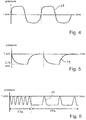
- Fig. 4, Fig. 5 and Fig. 6 depict different reciprocating pressure patterns 29.
- the pressure inside the storage chamber 3 reciprocates across the ambient pressure of 1 atmosphere, i.e. the pressure outside the container 5. That is, the pressure inside the storage chamber 3 fluctuates between a negative and positive pressure, in relation to the ambient pressure outside the container.
- forces resulting from the pressure difference will act in both directions on the container walls 7.
- the container 5 consequently needs to be built to withstand such varying forces.
- By reciprocating the pressure across the 1 atmosphere value (or more precisely, across the pressure value outside the container 5), one is able to obtain a relatively large pressure difference without large forces on the container walls 7 (as compared to the reciprocating pressure patterns that remains on one side of the 1 atmosphere value).
- An advantage of using positive pressures i.e. pressures that are higher than the pressure outside the container 5 (ambient pressure) is that it will enhance convection. That is, the temperature difference between the packing space 11 ( Fig. 1 ) and the storage chamber 3 (outside the packing space), will move faster towards an equalized condition, when the pressure is large.
- Another advantage of using positive pressures is that one will introduce more gas / air (more mass) into the packings 1, thereby better affecting the conditions / climate of the packing space 11.
- the reciprocating pressure pattern 29 shown in Fig. 5 reciprocates between the ambient pressure value of 1 atmosphere (i.e. the ambient pressure outside the container) and a lower pressure of 0,75 atmosphere. (I.e. a negative pressure of 0,25 atmosphere in relation to the ambient pressure; about -0,25 bar).
- the declining portion of the reciprocating pressure pattern shown in Fig. 5 can typically result when the pressure device 9 comprises an air pump (gas pump), which evacuates the storage chamber 3.
- the increasing portion can typically result from letting air/gas into the storage chamber 3 through a valve.
- the reciprocating pressure pattern 29 shown in Fig. 6 is divided into two phases.
- the pattern in a start-up phase 29a comprises pressure variations with a relatively high frequency, compared to the frequency of a storage phase 29b.
- the pressure device 9 is operated according to the pattern of the start-up phase 29a when the packings 1 with goods 15 need to be rapidly affected by the storage chamber conditions. E.g. if the packings 1 and goods 15 are too warm, compared to cold air in the storage chamber 3, the pressure is reciprocated quickly and/or often (high frequency) to obtain a swift adjustment of the conditions in the packing space 11 of the packings 1. After a while, after reaching satisfactory levels in the packing space 11, one may reduce the frequency.
- the reciprocating pressure pattern 29 has sections with a constant pressure. Such constant pressure sections can also advantageously have a pressure equal to the ambient pressure outside the container. That would reduce possible leaks of air into or out of the container 5 from the outside, during such periods of constant pressure.
- Fig. 7a shows another schematic, however more realistic, embodiment of a storage assembly 10.
- the storage assembly 10 has a substantial air tight insulated refrigerated container 5 providing a storage chamber 3. Inside the storage chamber 3, goods 15 in permeable packing 1 are shown to be stored and cooled.
- the container 5 is provided with a temperature device in the form of a refrigeration unit 25 adapted for introducing cooled air into the container 5.
- the refrigeration unit 25 may be mounted on a container wall 7. Alternatively, the refrigeration unit 25 may be provided as an integral part of the container, or provided in any other way know to the skilled person.
- the storage assembly 10 also comprises refrigeration unit control unit 37, controlling operation of the refrigeration unit 25, thereby controlling the temperature in the storage chamber 3.
- the pressure device is in the form of a vacuum device 9, adapted repeatedly evacuate the storage chamber 3.
- the storage chamber 3 is evacuated by removing air, whereby air pressure within the storage chamber 3 then is temporarily reduced below the ambient (atmospheric) pressure.
- air is also removed from the permeable packing 1, as explained above.
- the vacuum device 9 is provided with a vacuum device inlet 33, through which air is removed from the storage chamber 3.
- the vacuum device 9 may also be an integral part of the refrigeration unit or other parts of the storage assembly 10, and thus not have a dedicated inlet for removing air from the storage chamber 3.
- the vacuum device inlet 33 may be arranged along a periphery of the container 5, such as in an upper region of the storage chamber 3 to effectively remove hot air rising to the top of the storage chamber 3.
- the vacuum device inlet 33 may be arranged in a central area of the storage chamber 3 or in another position assumed to be substantially in a center of the packings 1 stored in the refrigerated container 5. Further, the position of the vacuum device inlet 33 may be variable, for example by providing a flexible hose in connection with the inlet. Hereby the vacuum device inlet 33 can be positioned according to the packings 1 stored to ensure an advantageous position of the inlet.
- the storage assembly 10 comprises a gas composition device 27, as discussed with reference to Fig. 3 .
- the gas composition device 27 can in one embodiment store compressed air or a mixture of gasses, such as oxygen, nitrogen and/or carbon dioxide.
- the air or gas mixture may be stored in a pressure cylinder, which may be easily replaced.
- the gas composition device 27 is adapted to introduce the stored air or air mixture into the storage space following evacuation, thereby increasing pressure and delivering an advantageous gas composition.
- the storage assembly 10 is adapted to increase the air pressure in the storage chamber 3 by introducing or re-introducing air.
- Air may be introduced by controlling the refrigeration unit 25 adapted for introducing cooled air into the container 5.
- air may be introduced from the gas composition device 27, or via the pressure device 9.
- One may also arrange a controlled valve (not shown) to let ambient air into the storage chamber 3 (provided the pressure in the chamber is lower than the ambient pressure).
- permeable packing 1 such as boxes, storage containers or the like.
- permeable packing 1 such as boxes, storage containers or the like.
- relatively hot air in the permeable packing may be replaced with colder air more effectively.
- the time required to cool goods to a desired temperature is reduced.
- a further effect of removing and re-introducing air is that humidity inside the storage space may be controlled.
- the pressure device 9 can be controlled to remove warm air from the storage chamber 3, the pressure device 9 in itself may have a dehumidifying effect.
- the storage assembly 10 may also be provided with a dedicated humidity controlling device.
- the refrigeration unit 25 comprises a refrigeration unit air intake 35 for drawing in ambient air surrounding the container 5 and the refrigeration unit 25 is adapted to introduce cooled ambient air into the storage chamber 3 to increase air pressure.
- the pressure device 9 is dimensioned according to the size of the storage chamber 3. It can be adapted to reduce the air pressure inside the storage chamber 3 between 5% and 50%, preferable between 5% and 25%, during evacuation.
- the actual reduction of the air pressure inside the storage space may be adjusted according to how sensitive the goods stored are to variations in air pressure and levels of pressure below atmospheric pressure.
- the pressure device 9 may also be operated so that the pressure in the storage chamber 3 has such positive pressures. It can be adapted to increase the air pressure inside the storage chamber 3 between 5% and 50%, preferable between 5% and 25%, during pressure increase, as compared to the ambient pressure (outside the container 5).
- the storage assembly 10 comprises an air-recirculation arrangement 41 for collecting air evacuated from the storage chamber by the pressure device 9.
- the air removed from the storage chamber 3 may be partly or fully re-introduced into the storage space by the air-recirculation arrangement 41.
- the air-recirculation arrangement 41 may be provided with a cleaning device configured to remove such undesirable gasses, before the air is re-introduced into the storage chamber 3.
- the air-recirculation arrangement 41 may be provided with a humidity controlling device for decreasing or increasing the humidity of the air introduced into the into the storage chamber 3.
- the duration of the step of increasing or decreasing the pressure in the storage chamber 3 be for instance from 20 to 40 seconds, or longer or shorter.
- the duration of the period wherein the pressure inside the storage chamber 3 is increased may also be from 20-40 seconds, or longer or shorter. If both the step of evacuating the storage space and the step of introducing air is from 20-40 seconds, the resulting frequency of what may be determined a cooling cycle is 40-80 seconds. It shall be noted, however, that these values are merely given as a possible example.
- the skilled person may employ a reciprocating pressure pattern with pressure values and a suitable pressure variation frequency which is suitable for the packings and goods in questions.
- the pressure device 9 may in some embodiments be in form of a gas pump, which can pump air into or out from the storage chamber 3.
- the specifications of the air pump may affect the possible reciprocating pressure patterns 29 (cf. Fig. 4 to Fig. 6 ).
- Fig. 8 and Fig. 9 schematically illustrate two other solutions for altering the pressure within the storage chamber 3.
- a piston 91 is able to reciprocate within a piston cylinder 93.
- the piston cylinder 93 communicates with the storage chamber 3, so that the pressure in the storage chamber 3 changes when the piston 91 is moved.
- a piston actuator 95 is connected to the piston 91 via a piston rod 97.
- the piston actuator 95 such as with the pressure device control module 19 (cf. Fig. 3 )
- the pressure in the storage chamber 3 can be repeatedly changed by reciprocating the piston 91. In this manner, the pressure is simply amended by changing the space available to the gas / air inside the storage chamber 3.
- Fig. 9 shows an alternative embodiment, wherein a part of the container wall 7 has a flexible wall 71.
- the flexible wall 71 can be flexed into or out from the storage chamber 3, so that the pressure in the storage chamber 3 changes.
- a wall actuator 73 connects to the flexible wall 71 via an attachment organ 75.
- the wall actuator 73 can be operated with the pressure device control unit 19. Also in this embodiment, the pressure change is obtained by amending the available space (i.e. the volume of the storage chamber 3).
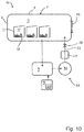
- Fig. 10 depicts an embodiment of the invention with an air-recirculation arrangement 41, as was discussed above.
- the pressure device 9 is configured to pump gas (air) out of the storage chamber 3, thereby reducing its pressure.
- air flow is indicated with broken lines.
- the temperature device 25, here in the form of a refrigeration unit, is connected in a re-entry flow path 26 that guides gas into the storage chamber 3.
- a controlled valve 28 governs the flow into the storage chamber 3.
- the air-recirculation arrangement 41 comprises an evacuated gas storage 30.
- the evacuated gas storage 30 is installed in the flow path between the pressure device 9 and the temperature device 25 (refrigeration unit).
- the gas flowing into and out from the storage chamber 3 would then flow through the pressure device 9.
- the pressure device 9 would be installed in the re-entry flow path 26.
- evacuation gas flow path there may be only one flow path constituting both the flow path for evacuated gas
Landscapes
- Engineering & Computer Science (AREA)
- Chemical & Material Sciences (AREA)
- Life Sciences & Earth Sciences (AREA)
- Chemical Kinetics & Catalysis (AREA)
- General Chemical & Material Sciences (AREA)
- Wood Science & Technology (AREA)
- Zoology (AREA)
- Food Science & Technology (AREA)
- Polymers & Plastics (AREA)
- Mechanical Engineering (AREA)
- Cold Air Circulating Systems And Constructional Details In Refrigerators (AREA)
Priority Applications (1)
| Application Number | Priority Date | Filing Date | Title |
|---|---|---|---|
| EP16156818.3A EP3210897A1 (de) | 2016-02-23 | 2016-02-23 | Aufbewahrungsanordnung und zugehöriges verfahren |
Applications Claiming Priority (1)
| Application Number | Priority Date | Filing Date | Title |
|---|---|---|---|
| EP16156818.3A EP3210897A1 (de) | 2016-02-23 | 2016-02-23 | Aufbewahrungsanordnung und zugehöriges verfahren |
Publications (1)
| Publication Number | Publication Date |
|---|---|
| EP3210897A1 true EP3210897A1 (de) | 2017-08-30 |
Family
ID=55436001
Family Applications (1)
| Application Number | Title | Priority Date | Filing Date |
|---|---|---|---|
| EP16156818.3A Withdrawn EP3210897A1 (de) | 2016-02-23 | 2016-02-23 | Aufbewahrungsanordnung und zugehöriges verfahren |
Country Status (1)
| Country | Link |
|---|---|
| EP (1) | EP3210897A1 (de) |
Citations (7)
| Publication number | Priority date | Publication date | Assignee | Title |
|---|---|---|---|---|
| GB1426917A (en) | 1972-04-20 | 1976-03-03 | Grumman Allied Industries | Storage of nonmineral matter |
| EP0437419A2 (de) * | 1990-01-09 | 1991-07-17 | Sm Vacuum Solich & Mayer | Verfahren zum Lagern und Frischhalten von Lebensmitteln sowie Vorrichtung zur Durchführung dieses Verfahrens |
| EP0703727A1 (de) * | 1993-06-17 | 1996-04-03 | CHIQUITA BRANDS, Inc | Verfahren zum fruchten-oder gemuese versenden und reifen mit gebrauch von behaelternsystem mit kontrollierter atmosphaere fuer verderblichen waren |
| US5565230A (en) * | 1993-01-08 | 1996-10-15 | Orchard View Farms, Inc. | Cherry preservation packaging method |
| WO2005106356A1 (en) * | 2004-05-03 | 2005-11-10 | Brancato Domenico Di Francesco Brancato & C. Snc | Improved process and apparatus for actuating and regulating forced circulation of air in cold-storage rooms |
| EP2546589A1 (de) * | 2011-07-12 | 2013-01-16 | A.P. Møller - Mærsk A/S | Temperatursteuerung in einem Kühlfrachtcontainer |
| WO2014035439A1 (en) * | 2012-08-31 | 2014-03-06 | Global Fresh Foods | Packages and methods for storing and transporting perishable foods |
-
2016
- 2016-02-23 EP EP16156818.3A patent/EP3210897A1/de not_active Withdrawn
Patent Citations (7)
| Publication number | Priority date | Publication date | Assignee | Title |
|---|---|---|---|---|
| GB1426917A (en) | 1972-04-20 | 1976-03-03 | Grumman Allied Industries | Storage of nonmineral matter |
| EP0437419A2 (de) * | 1990-01-09 | 1991-07-17 | Sm Vacuum Solich & Mayer | Verfahren zum Lagern und Frischhalten von Lebensmitteln sowie Vorrichtung zur Durchführung dieses Verfahrens |
| US5565230A (en) * | 1993-01-08 | 1996-10-15 | Orchard View Farms, Inc. | Cherry preservation packaging method |
| EP0703727A1 (de) * | 1993-06-17 | 1996-04-03 | CHIQUITA BRANDS, Inc | Verfahren zum fruchten-oder gemuese versenden und reifen mit gebrauch von behaelternsystem mit kontrollierter atmosphaere fuer verderblichen waren |
| WO2005106356A1 (en) * | 2004-05-03 | 2005-11-10 | Brancato Domenico Di Francesco Brancato & C. Snc | Improved process and apparatus for actuating and regulating forced circulation of air in cold-storage rooms |
| EP2546589A1 (de) * | 2011-07-12 | 2013-01-16 | A.P. Møller - Mærsk A/S | Temperatursteuerung in einem Kühlfrachtcontainer |
| WO2014035439A1 (en) * | 2012-08-31 | 2014-03-06 | Global Fresh Foods | Packages and methods for storing and transporting perishable foods |
Similar Documents
| Publication | Publication Date | Title |
|---|---|---|
| McDonald et al. | Vacuum cooling technology for the food processing industry: a review | |
| US20160245588A1 (en) | Botanical Freeze Drying System and Method | |
| CA2183318A1 (en) | Improvements in or relating to a method of transporting or storing perishable produce | |
| US10001315B2 (en) | Domestic/professional refrigerator | |
| IL272004B2 (en) | Method and device for pasteurizing and drying marijuana | |
| US20090211274A1 (en) | Process and apparatus for pretreatment of fresh food products | |
| DE102013224659A1 (de) | Kühlschrank und Verfahren zur Konservierung von Lebensmitteln in einem Kühlschrank | |
| CN103575033A (zh) | 具有可变压力的冰箱蔬菜间 | |
| ES2369290B2 (es) | Método, instalación y dispositivo para un tratamiento de secado, curado y conservación de alimentos sólidos o semisólidos. | |
| EP3210897A1 (de) | Aufbewahrungsanordnung und zugehöriges verfahren | |
| Opara et al. | Modified atmosphere packaging and controlled atmosphere packaging | |
| US20020012728A1 (en) | Hypobaric storage device | |
| CN104351328A (zh) | 一种果蔬开环气调保鲜装置及其工艺 | |
| JP6362467B2 (ja) | 真空冷却装置 | |
| JP2005233532A (ja) | 業務用冷蔵・冷凍庫、貯蔵用コンテナおよび冷凍倉庫 | |
| WO2015118277A1 (fr) | Procede de regulation de l'atmosphere d'une enceinte frigorifique | |
| NL1038791C2 (en) | A method of transporting compost. | |
| DE4302474C2 (de) | Vorrichtung zum Aufbewahren von Lebensmitteln | |
| JPH10103849A (ja) | 冷蔵庫 | |
| US20040033162A1 (en) | Storage device utilizing zeolites to control gaseous content | |
| Zheng et al. | Vacuum cooling of foods | |
| US20260060263A1 (en) | Vacuum cooling, constant flow partial pressure without refrigeration | |
| US1463723A (en) | Storing and preserving cabinet | |
| KR200328918Y1 (ko) | 에어이젝터를 이용한 진공 냉각장치 | |
| JPH08261620A (ja) | 真空冷却方法 |
Legal Events
| Date | Code | Title | Description |
|---|---|---|---|
| PUAI | Public reference made under article 153(3) epc to a published international application that has entered the european phase |
Free format text: ORIGINAL CODE: 0009012 |
|
| 17P | Request for examination filed |
Effective date: 20160223 |
|
| AK | Designated contracting states |
Kind code of ref document: A1 Designated state(s): AL AT BE BG CH CY CZ DE DK EE ES FI FR GB GR HR HU IE IS IT LI LT LU LV MC MK MT NL NO PL PT RO RS SE SI SK SM TR |
|
| AX | Request for extension of the european patent |
Extension state: BA ME |
|
| 17Q | First examination report despatched |
Effective date: 20171006 |
|
| STAA | Information on the status of an ep patent application or granted ep patent |
Free format text: STATUS: THE APPLICATION IS DEEMED TO BE WITHDRAWN |
|
| 18D | Application deemed to be withdrawn |
Effective date: 20181130 |